CN111936030A - Landmark estimation method and endoscope device - Google Patents
Landmark estimation method and endoscope deviceDownload PDFInfo
- Publication number
- CN111936030A CN111936030ACN201880092227.XACN201880092227ACN111936030ACN 111936030 ACN111936030 ACN 111936030ACN 201880092227 ACN201880092227 ACN 201880092227ACN 111936030 ACN111936030 ACN 111936030A
- Authority
- CN
- China
- Prior art keywords
- landmark
- insertion portion
- axis
- estimation method
- estimating
- Prior art date
- Legal status (The legal status is an assumption and is not a legal conclusion. Google has not performed a legal analysis and makes no representation as to the accuracy of the status listed.)
- Granted
Links
Images


Classifications
- G—PHYSICS
- G06—COMPUTING OR CALCULATING; COUNTING
- G06T—IMAGE DATA PROCESSING OR GENERATION, IN GENERAL
- G06T7/00—Image analysis
- G06T7/70—Determining position or orientation of objects or cameras
- G06T7/73—Determining position or orientation of objects or cameras using feature-based methods
- G—PHYSICS
- G06—COMPUTING OR CALCULATING; COUNTING
- G06T—IMAGE DATA PROCESSING OR GENERATION, IN GENERAL
- G06T7/00—Image analysis
- G06T7/0002—Inspection of images, e.g. flaw detection
- G06T7/0012—Biomedical image inspection
- A—HUMAN NECESSITIES
- A61—MEDICAL OR VETERINARY SCIENCE; HYGIENE
- A61B—DIAGNOSIS; SURGERY; IDENTIFICATION
- A61B1/00—Instruments for performing medical examinations of the interior of cavities or tubes of the body by visual or photographical inspection, e.g. endoscopes; Illuminating arrangements therefor
- A61B1/00002—Operational features of endoscopes
- A61B1/00004—Operational features of endoscopes characterised by electronic signal processing
- A61B1/00006—Operational features of endoscopes characterised by electronic signal processing of control signals
- A—HUMAN NECESSITIES
- A61—MEDICAL OR VETERINARY SCIENCE; HYGIENE
- A61B—DIAGNOSIS; SURGERY; IDENTIFICATION
- A61B1/00—Instruments for performing medical examinations of the interior of cavities or tubes of the body by visual or photographical inspection, e.g. endoscopes; Illuminating arrangements therefor
- A61B1/273—Instruments for performing medical examinations of the interior of cavities or tubes of the body by visual or photographical inspection, e.g. endoscopes; Illuminating arrangements therefor for the upper alimentary canal, e.g. oesophagoscopes, gastroscopes
- A61B1/2736—Gastroscopes
- G—PHYSICS
- G02—OPTICS
- G02B—OPTICAL ELEMENTS, SYSTEMS OR APPARATUS
- G02B23/00—Telescopes, e.g. binoculars; Periscopes; Instruments for viewing the inside of hollow bodies; Viewfinders; Optical aiming or sighting devices
- G02B23/24—Instruments or systems for viewing the inside of hollow bodies, e.g. fibrescopes
- G02B23/2476—Non-optical details, e.g. housings, mountings, supports
- G02B23/2484—Arrangements in relation to a camera or imaging device
- G—PHYSICS
- G06—COMPUTING OR CALCULATING; COUNTING
- G06T—IMAGE DATA PROCESSING OR GENERATION, IN GENERAL
- G06T7/00—Image analysis
- G06T7/10—Segmentation; Edge detection
- G06T7/13—Edge detection
- G—PHYSICS
- G06—COMPUTING OR CALCULATING; COUNTING
- G06T—IMAGE DATA PROCESSING OR GENERATION, IN GENERAL
- G06T7/00—Image analysis
- G06T7/60—Analysis of geometric attributes
- G—PHYSICS
- G06—COMPUTING OR CALCULATING; COUNTING
- G06T—IMAGE DATA PROCESSING OR GENERATION, IN GENERAL
- G06T7/00—Image analysis
- G06T7/70—Determining position or orientation of objects or cameras
- G—PHYSICS
- G06—COMPUTING OR CALCULATING; COUNTING
- G06T—IMAGE DATA PROCESSING OR GENERATION, IN GENERAL
- G06T7/00—Image analysis
- G06T7/90—Determination of colour characteristics
- H—ELECTRICITY
- H04—ELECTRIC COMMUNICATION TECHNIQUE
- H04N—PICTORIAL COMMUNICATION, e.g. TELEVISION
- H04N23/00—Cameras or camera modules comprising electronic image sensors; Control thereof
- H04N23/50—Constructional details
- H04N23/555—Constructional details for picking-up images in sites, inaccessible due to their dimensions or hazardous conditions, e.g. endoscopes or borescopes
- A—HUMAN NECESSITIES
- A61—MEDICAL OR VETERINARY SCIENCE; HYGIENE
- A61B—DIAGNOSIS; SURGERY; IDENTIFICATION
- A61B1/00—Instruments for performing medical examinations of the interior of cavities or tubes of the body by visual or photographical inspection, e.g. endoscopes; Illuminating arrangements therefor
- A61B1/04—Instruments for performing medical examinations of the interior of cavities or tubes of the body by visual or photographical inspection, e.g. endoscopes; Illuminating arrangements therefor combined with photographic or television appliances
- A61B1/045—Control thereof
- G—PHYSICS
- G06—COMPUTING OR CALCULATING; COUNTING
- G06T—IMAGE DATA PROCESSING OR GENERATION, IN GENERAL
- G06T2207/00—Indexing scheme for image analysis or image enhancement
- G06T2207/10—Image acquisition modality
- G06T2207/10024—Color image
- G—PHYSICS
- G06—COMPUTING OR CALCULATING; COUNTING
- G06T—IMAGE DATA PROCESSING OR GENERATION, IN GENERAL
- G06T2207/00—Indexing scheme for image analysis or image enhancement
- G06T2207/10—Image acquisition modality
- G06T2207/10068—Endoscopic image
- G—PHYSICS
- G06—COMPUTING OR CALCULATING; COUNTING
- G06T—IMAGE DATA PROCESSING OR GENERATION, IN GENERAL
- G06T2207/00—Indexing scheme for image analysis or image enhancement
- G06T2207/30—Subject of image; Context of image processing
- G06T2207/30004—Biomedical image processing
- G06T2207/30028—Colon; Small intestine
- G—PHYSICS
- G06—COMPUTING OR CALCULATING; COUNTING
- G06T—IMAGE DATA PROCESSING OR GENERATION, IN GENERAL
- G06T2207/00—Indexing scheme for image analysis or image enhancement
- G06T2207/30—Subject of image; Context of image processing
- G06T2207/30004—Biomedical image processing
- G06T2207/30092—Stomach; Gastric
- G—PHYSICS
- G06—COMPUTING OR CALCULATING; COUNTING
- G06T—IMAGE DATA PROCESSING OR GENERATION, IN GENERAL
- G06T2207/00—Indexing scheme for image analysis or image enhancement
- G06T2207/30—Subject of image; Context of image processing
- G06T2207/30004—Biomedical image processing
- G06T2207/30096—Tumor; Lesion
- G—PHYSICS
- G06—COMPUTING OR CALCULATING; COUNTING
- G06T—IMAGE DATA PROCESSING OR GENERATION, IN GENERAL
- G06T2207/00—Indexing scheme for image analysis or image enhancement
- G06T2207/30—Subject of image; Context of image processing
- G06T2207/30204—Marker
- H—ELECTRICITY
- H04—ELECTRIC COMMUNICATION TECHNIQUE
- H04N—PICTORIAL COMMUNICATION, e.g. TELEVISION
- H04N23/00—Cameras or camera modules comprising electronic image sensors; Control thereof
- H04N23/50—Constructional details
- H04N23/54—Mounting of pick-up tubes, electronic image sensors, deviation or focusing coils
- H—ELECTRICITY
- H04—ELECTRIC COMMUNICATION TECHNIQUE
- H04N—PICTORIAL COMMUNICATION, e.g. TELEVISION
- H04N7/00—Television systems
- H04N7/18—Closed-circuit television [CCTV] systems, i.e. systems in which the video signal is not broadcast
- H04N7/183—Closed-circuit television [CCTV] systems, i.e. systems in which the video signal is not broadcast for receiving images from a single remote source
Landscapes
- Engineering & Computer Science (AREA)
- Physics & Mathematics (AREA)
- General Physics & Mathematics (AREA)
- Health & Medical Sciences (AREA)
- Theoretical Computer Science (AREA)
- Computer Vision & Pattern Recognition (AREA)
- Life Sciences & Earth Sciences (AREA)
- Surgery (AREA)
- Optics & Photonics (AREA)
- General Health & Medical Sciences (AREA)
- Medical Informatics (AREA)
- Nuclear Medicine, Radiotherapy & Molecular Imaging (AREA)
- Radiology & Medical Imaging (AREA)
- Multimedia (AREA)
- Animal Behavior & Ethology (AREA)
- Veterinary Medicine (AREA)
- Astronomy & Astrophysics (AREA)
- Pathology (AREA)
- Biophysics (AREA)
- Biomedical Technology (AREA)
- Heart & Thoracic Surgery (AREA)
- Molecular Biology (AREA)
- Public Health (AREA)
- Signal Processing (AREA)
- Quality & Reliability (AREA)
- Gastroenterology & Hepatology (AREA)
- Geometry (AREA)
- Endoscopes (AREA)
- Instruments For Viewing The Inside Of Hollow Bodies (AREA)
Abstract
Description
Translated fromChinese技术领域technical field
本发明涉及界标估计方法及内窥镜装置。The present invention relates to a landmark estimation method and an endoscopic device.
背景技术Background technique
以往,在医疗领域和工业用领域中广泛利用内窥镜。例如,在医疗领域中,手术者可以观察显示在显示装置上的被检体内的内窥镜图像,发现和识别作为被摄体的病变部,进行使用了针对病变部的处置器具的处理。Conventionally, endoscopes have been widely used in medical fields and industrial fields. For example, in the medical field, an operator can observe an endoscopic image of a subject displayed on a display device, find and recognize a lesion as the subject, and perform treatment using a treatment tool for the lesion.
通常,已知基于从不同视点获得的多个图像的位置偏移信息,使用三角测量的原理来计算被摄体的三维坐标的技术。此外,还已知如下技术:向被摄体照射投影光,并且基于反射光到达传感器所需的时间、所拍摄的图案等来求出被摄体的三维坐标。Generally, there is known a technique for calculating three-dimensional coordinates of a subject using the principle of triangulation based on positional offset information of a plurality of images obtained from different viewpoints. In addition, a technique is also known in which a subject is irradiated with projection light, and the three-dimensional coordinates of the subject are obtained based on the time required for the reflected light to reach the sensor, a photographed pattern, and the like.
通过使用这些技术求出2点以上被摄体的三维坐标,计算被摄体的大小和体积等物理量。在利用内窥镜进行的观察中,通过使用这些技术,也能够计测肿瘤的尺寸、从贲门或肛门等成为界标的部位到肿瘤的距离等。By using these techniques, the three-dimensional coordinates of two or more objects are obtained, and physical quantities such as the size and volume of the object are calculated. In observation with an endoscope, by using these techniques, it is possible to measure the size of the tumor, the distance from a landmark site such as the cardia or the anus to the tumor, and the like.
在计算被摄体的物理量时,需要设定计测点和计测区域。如上所述,在内窥镜观察中,在计测从界标到肿瘤的距离的情况下,需要适当地设定界标的位置和肿瘤的位置。When calculating the physical quantity of the subject, it is necessary to set the measurement point and the measurement area. As described above, in the case of measuring the distance from the landmark to the tumor in endoscopic observation, it is necessary to appropriately set the position of the landmark and the position of the tumor.
另一方面,当肿瘤存在于作为界标的贲门或肛门附近时,需要使内窥镜镜体弯曲,并且以内窥镜的前端部回头的姿势拍摄对象。当以该姿势进行摄影时,内窥镜镜体自身映入内窥镜图像中。因此,不能利用映入的内窥镜镜体直接拍摄界标,所以难以适当地设定计测点。因此,提出了间接地估计计测点的方法。On the other hand, when a tumor exists in the vicinity of the cardia or anus as landmarks, it is necessary to bend the endoscope body and photograph the subject in a posture in which the distal end of the endoscope is turned back. When photographing in this posture, the endoscope scope itself is reflected in the endoscopic image. Therefore, since it is not possible to directly image the landmarks with the reflected endoscope scope, it is difficult to appropriately set the measurement point. Therefore, a method of indirectly estimating measurement points has been proposed.
例如,通过使用日本特开2016-80674号公报中提出的方法,设定包含难以直接指定的计测点的关心区域,通过分析该关心区域,能够间接地估计计测点。For example, by using the method proposed in Japanese Patent Application Laid-Open No. 2016-80674, a region of interest including a measurement point that is difficult to specify directly is set, and the measurement point can be estimated indirectly by analyzing the region of interest.
但是,在日本特开2016-80674号公报的估计方法中,需要在平面上设定关心区域。与此相对,在以内窥镜镜体回头的姿势拍摄界标附近的肿瘤而得到的图像中,存在内窥镜镜体自身的遮挡,并且内窥镜镜体相对于作为被摄体的管腔面倾斜地配置,所以无法在平面上设定关心区域。因此,在上述方法中,存在无法估计计测点的问题。However, in the estimation method of Japanese Patent Application Laid-Open No. 2016-80674, it is necessary to set the region of interest on the plane. On the other hand, in the image obtained by imaging the tumor near the landmark with the endoscope body turned back, there is occlusion by the endoscope body itself, and the endoscope body is relative to the lumen surface of the subject. It is arranged obliquely, so the region of interest cannot be set on the plane. Therefore, in the above-mentioned method, there is a problem that the measurement point cannot be estimated.
本发明是鉴于上述情况而完成的,其目的在于提供一种界标估计方法和内窥镜装置,即使在由于使内窥镜镜体弯曲而内窥镜自身映入内窥镜图像中从而界标被遮挡而无法直接指定为计测点的情况下,也能够高精度地估计界标的位置。The present invention has been made in view of the above-mentioned circumstances, and an object thereof is to provide a landmark estimation method and an endoscope apparatus in which a landmark is Even when it is blocked and cannot be directly specified as a measurement point, the position of the landmark can be estimated with high accuracy.
发明内容SUMMARY OF THE INVENTION
用于解决问题的手段means to solve the problem
本发明的一个方式的界标估计方法在利用插入部弯曲的内窥镜拍摄被摄体而得到的内窥镜图像中,估计界标的位置,该界标是存在于所述被摄体的孔部,且是供所述插入部贯穿的部位,其中,所述界标估计方法包含如下步骤:估计所述插入部的轴线;估计所述插入部与所述被摄体的边界;以及基于所述轴线和所述边界估计所述界标的位置。A landmark estimating method according to one aspect of the present invention estimates the position of a landmark, which is a hole existing in the subject, in an endoscopic image obtained by imaging a subject with an endoscope with a curved insertion portion, and is a site through which the insertion portion passes, wherein the landmark estimation method includes the steps of: estimating the axis of the insertion portion; estimating the boundary between the insertion portion and the subject; and based on the axis and The boundary estimates the location of the landmark.
本发明的一个方式的内窥镜装置具有界标估计部,该界标估计部在利用插入部弯曲的内窥镜拍摄被摄体而得到的内窥镜图像中,估计界标的位置,该界标是存在于所述被摄体上的孔部,且是供所述插入部贯穿的部位,其中,所述界标估计部具有:轴线估计部,其估计所述插入部的轴线;边界估计部,其估计所述插入部和所述被摄体之间的边界;以及界标位置估计部,其根据所述轴线和所述边界来估计所述界标的位置。An endoscope apparatus according to one aspect of the present invention includes a landmark estimating unit for estimating the position of a landmark that exists in an endoscopic image obtained by photographing a subject with an endoscope whose insertion portion is curved A hole portion in the subject, which is a portion through which the insertion portion passes, wherein the landmark estimation portion includes an axis estimation portion that estimates the axis of the insertion portion, and a boundary estimation portion that estimates a boundary between the insertion section and the subject; and a landmark position estimation section that estimates the position of the landmark based on the axis and the boundary.
附图说明Description of drawings
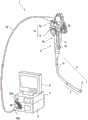
图1是表示本发明的实施方式的内窥镜装置1的整体结构的一例的立体图。FIG. 1 is a perspective view showing an example of the overall configuration of an
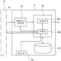
图2是表示与本发明的第1实施方式的处理器4的图像处理相关的结构的框图。FIG. 2 is a block diagram showing a configuration related to image processing by the processor 4 according to the first embodiment of the present invention.
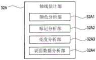
图3A是表示本发明的第1实施方式的控制运算部22的运算部22b的结构的框图。图3B是表示轴线估计部32A的结构的框图。FIG. 3A is a block diagram showing the configuration of the
图4是表示界标估计部32中的界标估计处理的流程的一例的流程图。FIG. 4 is a flowchart showing an example of the flow of landmark estimation processing in the
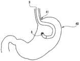
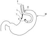
图5是表示成为检测对象的界标的一例的概略图。FIG. 5 is a schematic diagram showing an example of a landmark to be detected.
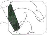
图6A是表示由图像生成部31生成的内窥镜图像的一例的图。FIG. 6A is a diagram showing an example of an endoscopic image generated by the
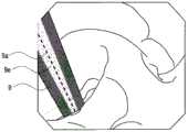
图6B是说明根据图6A的内窥镜图像估计出的界标位置的概略图。FIG. 6B is a schematic diagram illustrating landmark positions estimated from the endoscopic image of FIG. 6A .
图7是说明第2实施方式的插入部9的轴线9a估计位置的概略图。FIG. 7 is a schematic diagram illustrating the estimated position of the
图8是说明第2实施方式的变形例的插入部9的轴线9a估计位置的概略图。FIG. 8 is a schematic diagram illustrating the estimated position of the
图9是说明第3实施方式的插入部9的轴线9a估计位置的概略图。FIG. 9 is a schematic diagram illustrating the estimated position of the
图10是说明第4实施方式的内窥镜2的结构的一例的概略图。FIG. 10 is a schematic diagram illustrating an example of the configuration of the
图11是说明第4实施方式的内窥镜2的结构的另一例的概略图。FIG. 11 is a schematic diagram illustrating another example of the configuration of the
图12是说明第4实施方式的内窥镜2的结构的另一例的概略图。FIG. 12 is a schematic diagram illustrating another example of the configuration of the
图13是说明第4实施方式的插入部9的轴线9a估计位置的概略图。FIG. 13 is a schematic diagram illustrating the estimated position of the
图14是说明第4实施方式的插入部9的轴线9a的另一估计位置的概略图。14 is a schematic diagram illustrating another estimated position of the
图15是表示第5实施方式的控制运算部22的运算部22b的结构的框图。FIG. 15 is a block diagram showing the configuration of the
图16是表示界标与病变部的直线距离的概略图。FIG. 16 is a schematic diagram showing a linear distance between a landmark and a lesion.
图17是表示界标和病变部的沿面距离的概略图。FIG. 17 is a schematic diagram showing the creeping distance between a landmark and a lesion.
图18是说明第6实施方式的内窥镜2的结构的一例的概略图。FIG. 18 is a schematic diagram illustrating an example of the configuration of the
具体实施方式Detailed ways
以下,参照附图说明实施方式。Hereinafter, embodiments will be described with reference to the drawings.
(第1实施方式)(first embodiment)
图1是表示本发明的实施方式的内窥镜装置的整体结构的一例的立体图。如图1所示,本实施方式的内窥镜装置1主要由作为内窥镜镜体的电子内窥镜(以下简称为内窥镜)2、光源装置3、处理器4和监视器5构成。FIG. 1 is a perspective view showing an example of the overall configuration of an endoscope apparatus according to an embodiment of the present invention. As shown in FIG. 1 , an
内窥镜2构成为具有:长条且细长的插入部9、操作部10、以及作为电缆的通用缆线19。内窥镜2的插入部9构成为从前端起依次具有前端部6、弯曲部7和挠性管部8。在前端部6设有未图示的照明窗和观察窗,照明光从照明窗向被检体射出,来自被检体的返回光入射到观察窗。在前端部6中,作为拍摄被摄体的单元,配置有CCD、CMOS等固体摄像元件,对从观察窗入射的光所形成的被摄体像进行光电转换而输出摄像信号。摄像信号通过通用缆线19提供给处理器4。The
用于对插入部9的弯曲部7进行弯曲操作的弯曲操作部14旋转自如地配设于操作部10,并且操作部10设有包括对焦开关15在内的各种内窥镜功能的开关类等。另外,弯曲操作部14以重叠的方式配设有UD弯曲操作旋钮12和RL弯曲操作旋钮13,该UD弯曲操作旋钮12用于对弯曲部7向上下方向进行弯曲操作,该RL弯曲操作旋钮13用于对弯曲部7向左右方向进行弯曲操作。A
并且,插入部9和操作部10的连接部构成为具有:把持部11,其兼用作用户的把持部;以及处置器具通道贯穿部18,其配设在设于该把持部11和插入部9的挠性管部8的一端之间的防折部上,成为供配设在插入部9上的各种处置部贯穿的处置器具通道的开口部。Further, the connection portion between the
从操作部10延伸设置的通用缆线19在延伸端具有相对于光源装置3装卸自如的镜体连接器19a。并且,镜体连接器19a延伸设置有线圈状的螺旋缆线20,在该螺旋缆线20的延伸端设有作为相对于处理器4装卸自如的连接器的镜体连接器20a。另外,本实施方式的内窥镜2通过配设在通用缆线19、操作部10以及插入部9上的照明单元的光导缆线,从光源装置3向前端部6传送照明光。The
处理器4与显示内窥镜图像的监视器5电连接,对由搭载在内窥镜2上的CCD等摄像单元进行光电转换而得的摄像信号进行处理,作为图像信号输出到监视器5。在监视器5上显示内窥镜图像。The processor 4 is electrically connected to a
图2是表示与处理器4的图像处理相关的结构的框图。处理器4是具有摄像信号取得部21、控制运算部22、存储装置23和输入部24的图像处理装置。控制运算部22是包括控制部22a和运算部22b的电路。FIG. 2 is a block diagram showing a configuration related to image processing by the processor 4 . The processor 4 is an image processing device including an imaging signal acquisition unit 21 , a control
摄像信号取得部21是在控制部22a的控制下接收并取得来自内窥镜2的摄像元件的摄像信号,并将其输出到控制运算部22的电路。The imaging signal acquisition unit 21 is a circuit that receives and acquires imaging signals from the imaging element of the
控制部22a包括中央处理装置(以下称为CPU)、ROM、RAM等,进行处理器4整体的动作控制,并且根据手术者对输入部24的指示,进行内窥镜2的摄像元件的驱动控制、基于来自内窥镜2的操作部10的各种操作信号的各种电路的控制、向存储装置23记录各种数据以及从存储装置23读出各种数据的控制、以及图像处理的控制。The
即,控制部22a根据在输入部24中进行的指示或输入,控制内窥镜装置1的动作,输出针对各部的控制信号或设定信号。That is, the
运算部22b是如下的电路:在控制部22a的控制下,根据由摄像信号取得部21取得的摄像信号,执行各种图像处理和各种运算处理,并且生成显示在监视器5上的内窥镜图像的图像信号和各种显示信息,并输出到监视器5。The
另外,也可以通过软件程序进行控制运算部22中的控制部22a和运算部22b的处理的全部或一部分。In addition, all or part of the processing of the
存储装置23是硬盘装置等大容量的存储装置,存储通过内窥镜检查得到的被检体内的内窥镜图像的图像数据以及辅助信息等各种数据。The
输入部24是具有各种按钮的操作面板,是用于手术者向处理器4提供内窥镜装置1的各种设定、各种指示等的输入装置。The
图3A是表示本实施方式中的控制运算部22的运算部22b的结构的框图。FIG. 3A is a block diagram showing the configuration of the
运算部22b是包含图像生成部31、界标估计部32的电路。The
图像生成部31是接收摄像信号,根据观察模式,根据摄像信号生成内窥镜图像的电路。对内窥镜图像进行规定的强调处理、各种校正处理、使各种信息和菜单画面等重叠显示的重叠处理等。The
界标估计部32是估计内窥镜图像中的内窥镜1的插入部9插入到观察部位的孔(例如,消化道内窥镜检查中的胃的幽门部等)即界标的位置的电路。界标估计部32由轴线估计部32A、边界估计部32B和界标位置估计部32C构成。The
轴线估计部32A是从内窥镜图像中提取内窥镜1的插入部9,估计插入部9的中心轴的电路。图3B是表示轴线估计部32A的结构的框图。关于图3B所示的轴线估计部32A中的各部的动作,在下述的说明的对应处进行后述。图3B不仅示出了下面说明的本实施方式的结构,而且示出了在本实施方式之后说明的第2至第6实施方式的结构。The
边界估计部32B是在映入内窥镜图像中的插入部9中将插入源侧(基端侧、远离前端部6的一侧)估计为边界的电路。The
界标位置估计部32C是使用所估计的内窥镜1的插入部9的中心轴和插入部9与被摄体的边界来估计界标位置的电路。The landmark
图4是表示界标估计部32中的界标估计处理的流程的一例的流程图。另外,图5是表示成为检测对象的界标的一例的概略图。作为在使内窥镜2的插入部9弯曲而前端部6回头的姿势下拍摄被摄体的状况,如图5所示,除了观察胃40的幽门部41附近的肿瘤的情况之外,还可以列举观察大肠的肛门部附近的肿瘤的情况、工业用内窥镜中的飞机引擎的接入端口的检查等。在图5的情况下,作为供插入部9插入到胃内部的孔部的幽门部9成为界标。FIG. 4 is a flowchart showing an example of the flow of landmark estimation processing in the
在界标估计处理之前,控制部22a控制光源的驱动和内窥镜2的摄像元件的驱动,并且控制摄像信号取得部21,由此运算部22b取得来自内窥镜2的摄像信号。运算部22b的图像生成部31在控制部22a的控制下根据摄像信号生成内窥镜图像。图6A是表示由图像生成部31生成的内窥镜图像的一例的图。Before the landmark estimation process, the
界标估计部32根据所生成的内窥镜图像,估计插入部9的轴线(S1)。S1的处理涉及图3A中的轴线估计部32A。轴线的估计例如可以通过从内窥镜图像中提取作为对象的插入部9,确定插入部9的长度方向来进行估计。The
接着,界标估计部32估计所提取的插入部9与被摄体的边界(S2)。S2中的处理涉及图3A中的边界估计部32B。在以前端部6回头的姿势拍摄被摄体的情况下,插入部9的前端侧必须位于内窥镜图像的周缘侧,插入部9的插入源侧必须位于内窥镜图像的中心侧。因此,能够将图像上的插入部9与被摄体(在图5的情况下为胃的内壁)的边界线中的、与插入部9的长度方向交叉且位于内窥镜图像的中心侧的边界线,估计为插入部9与被摄体的边界。Next, the
最后,界标估计部32估计界标的位置(S3)。S3的处理涉及图3A中的界标位置估计部32C。图6B是说明根据图6A的内窥镜图像估计出的界标位置的概略图。界标L的位置可以估计为在S1中估计的插入部9的轴线9a与在S2中估计的边界9b的交点。Finally, the
如上所述,根据上述实施方式的界标估计方法,即使在由于使内窥镜插入部弯曲而插入部自身映入内窥镜图像中从而界标被遮挡而无法直接指定为计测点的情况下,也可以高精度地估计界标的位置。As described above, according to the landmark estimating method of the above-described embodiment, even when the insertion portion itself is reflected in the endoscopic image by bending the endoscope insertion portion, the landmark is blocked and cannot be directly specified as the measurement point. The locations of landmarks can also be estimated with high accuracy.
(第2实施方式)(Second Embodiment)
在上述第1实施方式中,通过检测插入部9的长度方向来估计插入部9的轴线9a,然而在本实施方式中,使用图像处理来检测轴线9a。本实施方式的内窥镜装置具有与第1实施方式的内窥镜装置1相同的结构,对相同的结构要素赋予相同标号并省略说明。另外,按照与图4所示的流程图相同的顺序进行本实施方式的界标估计处理。但是,S1的具体方法与第1实施方式不同。下面,说明本实施方式的图4的S1的方法、即估计插入部9的轴线9a的具体方法。另外,本实施方式中的S1的处理涉及图3B中的颜色分析部32A1。In the above-described first embodiment, the
图7是说明第2实施方式的插入部9的轴线9a估计位置的概略图。图7示出对图6A所示的内窥镜图像实施后述的处理,检测出插入部9的边缘的状态。在估计插入部9的轴线9a时,轴线估计部32A的颜色分析部32A1使用插入部9的颜色(例如黑色)和体腔内的颜色(红色)的差异,来分割插入部9区域和体腔区域,检测插入部9的边缘。在边缘检测中,可以使用霍夫变换等现有的方法。FIG. 7 is a schematic diagram illustrating the estimated position of the
根据检测出的边缘,计算将插入部9的径向宽度二等分的沿着插入部9的长度方向的直线(中心线)。中心线的计算也可以使用基于图像矩的主轴线提取等现有的方法。将这样得到的中心线估计为插入部9的轴线9a。From the detected edge, a straight line (center line) along the longitudinal direction of the
如上所述,根据本实施方式,也能够得到与第1实施方式相同的效果。As described above, also according to the present embodiment, the same effects as those of the first embodiment can be obtained.
(第2实施方式的变形例)(Variation of the second embodiment)
在上述第2实施方式中,通过颜色分析来检测插入部9的边缘,从而估计插入部9的轴线9a,但是在本变形例中,使用设置在插入部9上的标记来检测轴线9a。本变形例的内窥镜装置具有与第1实施方式的内窥镜装置1相同的结构,对相同的结构要素赋予相同标号并省略说明。另外,按照与图4所示的流程图相同的顺序进行本实施方式的界标估计处理。但是,S1的具体方法与第2实施方式不同。下面,说明本变形例的图4的S1的方法,即估计插入部9的轴线9a的具体方法。另外,本变形例中的S1的处理涉及图3B中的标记分析部32A2。In the above-described second embodiment, the edge of the
图8是说明第2实施方式的变形例的插入部9的轴线9a估计位置的概略图。通常,在内窥镜1的插入部9上,距前端以一定位置(或一定间隔)设有标记9d。标记9d设有颜色与插入部9的颜色不同的标记,以便能够在内窥镜图像上容易地识别。例如,在插入部9的颜色是黑色的情况下,设置相反颜色的白色标记9d。并且,标记9d优选配置成无论插入方向、插入深度、插入的朝向等插入部9的插入状态如何,总是能够在内窥镜图像上识别标记9d。因此,例如沿着插入部9的径向绕插入部9d的外缘一周的形状的标记9d距前端以一定间隔配置。FIG. 8 is a schematic diagram illustrating the estimated position of the
轴线估计部32A的标记分析部32A2根据预先保存在存储部23等中的与标记的形状以及颜色相关的信息,从内窥镜图像中检测标记9d。如上所述,在沿着插入部9的径向设有绕插入部9d的外缘一周的形状的标记9d的情况下,将与检测为标记9d的线段垂直的方向估计为轴向。另外,轴线的估计方法根据标记9d的形状而不同。例如,在沿着插入部9的长度方向配置标记9d的情况下,将与标记9d相同的方向估计为轴向,其中,标记9d具有如数条直线那样以一定间隔附加了刻度的直线形状。The marker analysis unit 32A2 of the
如上所述,根据本变形例,也能够得到与第1、第2实施方式相同的效果。As described above, also according to the present modification, the same effects as those of the first and second embodiments can be obtained.
(第3实施方式)(third embodiment)
在上述实施方式中,从内窥镜图像上提取插入部9的长度方向、边缘、标记等,根据这些信息来估计轴线9a,但是在本实施方式中,不同点在于还使用图像的亮度信息来估计轴线9a。本变形例的内窥镜装置具有与第1实施方式的内窥镜装置1相同的结构,对相同的结构要素赋予相同标号并省略说明。另外,按照与图4所示的流程图相同的顺序进行本实施方式的界标估计处理。但是,S1的具体方法与第2实施方式不同。下面,说明本变形例的图4的S1的方法,即估计插入部9的轴线9a的具体方法。另外,本变形例中的S1的处理涉及图3B中的亮度分析部32A3。In the above-described embodiment, the longitudinal direction, the edge, the mark, etc. of the
图9是说明第3实施方式的插入部9的轴线9a估计位置的概略图。亮度分析部32A3在图6A所示的内窥镜图像中计算各像素的亮度值。通常,插入部9的表面被进行镜面处理。因此,照射到体腔内的照明光被插入部9的表面镜面反射。由于插入部9是大致筒状,所以越接近插入部9的轴线9a,反射角越小,反射光相对于配置在前端部6的摄像面垂直入射。另一方面,越远离插入部的轴线9a而接近边缘,反射光的入射角越大,反射光相对于配置在前端部6的摄像面倾斜地入射。FIG. 9 is a schematic diagram illustrating the estimated position of the
即,在内窥镜图像中,越是位于插入部9的轴线9a附近的像素,亮度值越高,随着远离轴线9a,亮度值越低。利用该现象,检测计算出的像素值高于预定阈值的区域,能够估计为在该区域(高亮度区域9e)的中心轴上存在插入部9的轴线9a。That is, in the endoscopic image, the pixels located near the
这样,通过利用镜面反射,即使在没有拍摄到本来的纹理的状况下(例如,在插入部9与体腔内的色差较小,难以利用颜色进行区域分割的情况下,或者难以检测出设定在插入部9中的标记9d的情况下),也能够稳定地估计轴线9a。另外,亮度分析部32A3也可以用于判定通过上述实施方式或变形例估计的轴线9a是否存在于高亮度区域。在这种情况下,由于能够排除错误地估计的轴线9a,所以轴线9a的估计精度提高。In this way, by using specular reflection, even in the situation where the original texture is not captured (for example, when the color difference between the
如上所述,根据本实施方式,也能够得到与第1、第2实施方式相同的效果。进而,通过与第1、第2实施方式组合,能够提高轴线9a的检测精度。As described above, also according to the present embodiment, the same effects as those of the first and second embodiments can be obtained. Furthermore, by combining with 1st, 2nd embodiment, the detection precision of the
(第4实施例)(4th embodiment)
在上述实施方式中,根据二维的内窥镜图像来估计界标,但在本实施方式中,取得三维的内窥镜图像(3D表面数据),根据该数据来估计界标。本实施方式的内窥镜装置除了设置在内窥镜2中的取得3D表面数据的单元以外,具有与第1实施方式的内窥镜装置1相同的结构,对于相同的结构要素赋予相同标号并省略说明。In the above-described embodiments, landmarks are estimated from two-dimensional endoscopic images, but in this embodiment, three-dimensional endoscopic images (3D surface data) are acquired, and landmarks are estimated from the data. The endoscope apparatus of the present embodiment has the same configuration as the
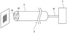
图10是说明本实施方式的内窥镜2的结构的一例的概略图。本实施方式的内窥镜2具有投影式计测设备41,作为取得3D表面数据的单元。投影式计测设备41采用TOF(Time OFflight:飞行时间)法,即对被摄体照射投影光,检测来自被摄体的反射光。通过计测从照射投影光到检测到反射光的时间,根据该计测时间计算被摄体的三维坐标。FIG. 10 is a schematic diagram illustrating an example of the configuration of the
投影式计测设备41例如从处置器具通道贯穿部18插入,通过操作部10、插入部9的内部,从设置在前端部6上的处置器具通道44照射投影光。来自被摄体的反射光从处置器具通道44入射,由投影式计测设备41的未图示的检测部检测,计测直到检测到为止所需的时间。另外,来自被摄体的反射光也可以构成为经由设置在前端部6上的处置器具通道44以外的窗进行检测。例如,也可以构成为经由观察窗42利用摄像元件进行检测。The projection
另外,投影式计测设备41只要是能够以非接触方式取得3D表面数据的设备,则可以是使用了任何方法的设备,可以是不像上述那样根据反射光的返回时间对现有的设备计算三维坐标,而使用图案投影法(对被摄体投影网格图案等特定的已知图案,根据由摄像元件拍摄的图案的变形来计算被摄体的三维表面数据的方法)等其他方法的设备。In addition, the projection
另外,如图11所示,计测用的投影光或特定图案也可以构成为从光源装置3经由照明窗43向被摄体照射。图11是说明第4实施方式的内窥镜2的结构的另一例的概略图。In addition, as shown in FIG. 11 , the projection light or the specific pattern for measurement may be configured to be irradiated to the subject from the
另外,如图12所示,也可以在内窥镜2上搭载立体摄像系统,根据2张图像的位置偏移信息,使用三角测量的原理计算被摄体的3D表面数据,所述2张图像是基于由位置不同的2个观察窗42a、42b接收到的被摄体的反射光而得到的。图12是说明第4实施方式的内窥镜2的结构的另一例的概略图。In addition, as shown in FIG. 12 , a stereo camera system may be mounted on the
本实施方式的界标估计处理按照与图4所示的流程图同样的顺序进行。但是,S1和S3的具体方法与上述实施方式不同。下面,说明本变形例的图4的S1的方法,即估计插入部9的轴线9a的具体方法。另外,本实施方式中的S1的处理涉及图3B中的表面数据分析部32A4。The landmark estimation process of the present embodiment is performed in the same procedure as the flowchart shown in FIG. 4 . However, the specific methods of S1 and S3 are different from those of the above-described embodiment. Next, the method of S1 of FIG. 4 of this modification, ie, the specific method of estimating the
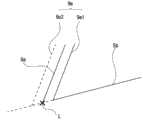
图13是说明第4实施方式的插入部9的轴线9a估计位置的概略图。表面数据分析部32A取得被摄体的3D表面数据。根据表面数据,检测内窥镜2的插入部9的长度方向的边缘。在图13中,在插入部9的边缘9e中,用实线表示可作为表面数据取得的边缘9e1,用虚线表示不能作为表面数据取得的边缘9a2。在本实施方式中,将可作为表面数据取得的边缘9e1估计为插入部9的轴线9a。FIG. 13 is a schematic diagram illustrating the estimated position of the
另外,也可以根据插入部9与体腔的边界的表面数据来估计插入部9的截面形状(椭圆形状),将通过所估计的截面的中心并与可作为表面数据取得的边缘9e1平行的直线估计为轴线9a。图14是说明第4实施方式的插入部9的轴线9a的其他估计位置的概略图。插入部9的截面形状可以根据表面数据来估计,也可以将插入部9的截面形状的设计数据预先保存在设置于内窥镜2的未图示的存储部中,并参照该设计数据。Alternatively, the cross-sectional shape (elliptical shape) of the
接着,在估计出插入部9与体腔的边界后(S2),在S3中进行界标估计。具体而言,将根据3D表面数据被检测为体腔(例如胃壁)的面Sb与在S1中估计出的轴线9a的交点估计为界标L。Next, after estimating the boundary between the
如上所述,根据本实施方式,也能够得到与第1实施方式相同的效果。As described above, also according to the present embodiment, the same effects as those of the first embodiment can be obtained.
(第5实施方式)(Fifth Embodiment)
在本实施方式中,检测体腔内的病变部,计算在上述各实施方式中估计出的界标与病变部的距离。本实施方式的内窥镜装置具有与第1实施方式的内窥镜装置1相同的结构,对相同的结构要素赋予相同标号并省略说明。以下,说明与第1实施方式不同的运算部22b的结构。In the present embodiment, the lesion in the body cavity is detected, and the distance between the landmark and the lesion estimated in each of the above-described embodiments is calculated. The endoscope apparatus of the present embodiment has the same configuration as that of the
图15是表示本发明的第5实施方式的控制运算部22的运算部22b的结构的框图。本实施方式的运算部22b除了图像生成部31、界标估计部32以外,还具有病变检测部33和距离分析部34。FIG. 15 is a block diagram showing the configuration of the
病变检测部33例如通过进行将图像识别器应用于内窥镜图像的处理,来从该图像中检测病变部,其中,该图像识别器预先取得了可利用深度学习等学习方法来识别肿瘤(息肉)图像的功能。另外,病变区域的检测不限于上述所示的学习方法,也可以使用其他方法。例如,可以使用日本特开2007-244518号公报所公开的息肉候选检测处理等。The lesion detection unit 33 detects a lesion from the endoscopic image by applying, for example, a process of applying an image recognizer that has acquired in advance that a tumor (polyp) can be recognized by a learning method such as deep learning. ) image function. In addition, the detection of the lesion area is not limited to the learning method shown above, and other methods may be used. For example, the polyp candidate detection process or the like disclosed in Japanese Patent Laid-Open No. 2007-244518 can be used.
距离分析部34计算病变部与界标之间的距离。另外,2点间的距离可以作为直线距离来计算,在取得了被摄体的3D表面数据的情况下,也可以求出沿体腔内表面的沿面距离。The
图16是表示界标与病变部的直线距离的概略图。在计算直线距离的情况下,如图16所示,距离分析部34用直线连接所估计的界标L和所检测的病变部T,计算它们之间的距离。图17是表示界标和病变部的沿面距离的概略图。在计算沿面距离的情况下,距离分析部34如图17所示,用直线连接估计出的界标L和检测出的病变部T,计算它们之间的距离。FIG. 16 is a schematic diagram showing a linear distance between a landmark and a lesion. When calculating the straight-line distance, as shown in FIG. 16 , the
如上所述,根据本实施方式的估计方法,可以获得与第1实施方式相同的效果,并且可以使用所估计的界标的位置来计测与病变部的距离,可以生成并提示对手术者的手术技术有用的信息。As described above, according to the estimation method of the present embodiment, the same effects as those of the first embodiment can be obtained, the distance to the lesion can be measured using the estimated position of the landmark, and the operation for the operator can be generated and presented. Technically useful information.
(第6实施方式)(Sixth Embodiment)
在上述实施方式中,与内窥镜的状态无关地进行界标估计,但在本实施方式中,仅在插入部9处于弯曲状态的情况下进行界标估计。本实施方式的内窥镜装置除了对设置在内窥镜2中的插入部9的弯曲进行检测的单元以外,还具有与第1实施方式的内窥镜装置1相同的结构,对相同的结构要素标注相同标号并省略说明。In the above-described embodiment, the landmark estimation is performed regardless of the state of the endoscope, but in the present embodiment, the landmark estimation is performed only when the
图18是说明本实施方式的内窥镜2的结构的一例的概略图。关于本实施方式的内窥镜2,在内窥镜2中设有使插入部9弯曲的线51。线的一端与感压装置52连接。当为了使插入部9弯曲而对线51施加压力时,感压装置52检测到该情况。感压装置52的检测结果被输出到控制运算部22。另外,检测插入部9的弯曲的手段不限于上述感压装置52的检测,也可以使用其他手段。FIG. 18 is a schematic diagram illustrating an example of the configuration of the
控制运算部22仅在感压装置52检测到线压的情况下,执行界标估计部32中的各处理。另外,也可以根据由感压装置52检测到的线压来估计插入部9的弯曲角度,并用于估计插入部的轴线9a。The
如上所述,根据上述各实施方式及变形例,即使在由于使内窥镜插入部弯曲而插入部自身映入内窥镜图像中从而界标被遮挡而无法直接指定为计测点的情况下,也可以高精度地估计界标的位置。As described above, according to each of the above-described embodiments and modifications, even when the insertion portion itself is reflected in the endoscopic image by bending the endoscope insertion portion, the landmarks are blocked and the measurement point cannot be directly specified. The locations of landmarks can also be estimated with high accuracy.
本发明不限于上述实施例,当然可以在不脱离发明主旨的范围内进行各种变更和应用。The present invention is not limited to the above-described embodiments, and of course various modifications and applications can be made without departing from the gist of the invention.
Claims (12)
Applications Claiming Priority (1)
| Application Number | Priority Date | Filing Date | Title |
|---|---|---|---|
| PCT/JP2018/023833WO2019244345A1 (en) | 2018-06-22 | 2018-06-22 | Landmark estimation method and endoscope device |
Publications (2)
| Publication Number | Publication Date |
|---|---|
| CN111936030Atrue CN111936030A (en) | 2020-11-13 |
| CN111936030B CN111936030B (en) | 2024-09-20 |
Family
ID=68983652
Family Applications (1)
| Application Number | Title | Priority Date | Filing Date |
|---|---|---|---|
| CN201880092227.XAActiveCN111936030B (en) | 2018-06-22 | 2018-06-22 | Landmark estimation method, endoscope device and storage medium |
Country Status (4)
| Country | Link |
|---|---|
| US (1) | US11430114B2 (en) |
| JP (1) | JP6987243B2 (en) |
| CN (1) | CN111936030B (en) |
| WO (1) | WO2019244345A1 (en) |
Families Citing this family (2)
| Publication number | Priority date | Publication date | Assignee | Title |
|---|---|---|---|---|
| CN115279250B (en)* | 2020-04-28 | 2025-04-29 | 豪雅株式会社 | Endoscope system |
| JPWO2022202400A1 (en)* | 2021-03-22 | 2022-09-29 |
Citations (18)
| Publication number | Priority date | Publication date | Assignee | Title |
|---|---|---|---|---|
| JP2006187551A (en)* | 2005-01-07 | 2006-07-20 | Olympus Corp | Image processor for esophageal mucous membrane |
| JP2007244517A (en)* | 2006-03-14 | 2007-09-27 | Olympus Medical Systems Corp | Medical image processing apparatus and medical image processing method |
| CN101065052A (en)* | 2004-12-27 | 2007-10-31 | 奥林巴斯株式会社 | Medical image processing device and method |
| CN101268953A (en)* | 2007-03-23 | 2008-09-24 | 奥林巴斯医疗株式会社 | Medical apparatus |
| CN101530313A (en)* | 2008-03-10 | 2009-09-16 | 富士胶片株式会社 | Endoscopy system and method therefor |
| CN101652092A (en)* | 2007-06-20 | 2010-02-17 | 奥林巴斯医疗株式会社 | Endoscope system, imaging system, and image processing apparatus |
| EP2215960A1 (en)* | 2007-11-29 | 2010-08-11 | Olympus Medical Systems Corp. | Endoscope curve control device and endoscope system |
| US20100249506A1 (en)* | 2009-03-26 | 2010-09-30 | Intuitive Surgical, Inc. | Method and system for assisting an operator in endoscopic navigation |
| US20110060185A1 (en)* | 2009-06-01 | 2011-03-10 | Olympus Medical Systems Corp. | Medical device system and calibration method for medical instrument |
| CN102449666A (en)* | 2009-03-26 | 2012-05-09 | 直观外科手术操作公司 | System for providing visual guidance for steering the tip of an endoscopic device toward one or more landmarks and assisting an operator in endoscopic navigation |
| CN104125795A (en)* | 2012-05-23 | 2014-10-29 | 奥林巴斯医疗株式会社 | Electronic endoscope system |
| US20150142372A1 (en)* | 2013-11-19 | 2015-05-21 | Polaris Surgical, LLC | Prosthetic placement tool and associated methods |
| US20150170352A1 (en)* | 2013-12-17 | 2015-06-18 | General Electric Company | Method and device for automatically identifying the deepest point on the surface of an anomaly |
| CN104755009A (en)* | 2013-04-15 | 2015-07-01 | 奥林巴斯医疗株式会社 | Endoscope system |
| CN106068093A (en)* | 2014-04-08 | 2016-11-02 | 奥林巴斯株式会社 | Endoscopic system |
| WO2017054817A1 (en)* | 2015-10-01 | 2017-04-06 | Olaf Christiansen | Endoscopic image processing system for surgery using means which generate geometric distance information in the detection region of an optical digital camera |
| WO2017081821A1 (en)* | 2015-11-13 | 2017-05-18 | オリンパス株式会社 | Method for estimating state of endoscope |
| US20180084970A1 (en)* | 2016-09-28 | 2018-03-29 | Fujifilm Corporation | Image display device, image display method, and program |
Family Cites Families (14)
| Publication number | Priority date | Publication date | Assignee | Title |
|---|---|---|---|---|
| WO2006087981A1 (en)* | 2005-02-15 | 2006-08-24 | Olympus Corporation | Medical image processing device, lumen image processing device, lumen image processing method, and programs for them |
| JP5477800B2 (en)* | 2008-02-27 | 2014-04-23 | 株式会社日立製作所 | Method of operating rotation state detection device and rotation state detection device |
| JP2009254783A (en)* | 2008-03-25 | 2009-11-05 | Panasonic Electric Works Co Ltd | Endoscope system and endoscopic operation training system |
| US8870751B2 (en) | 2010-09-28 | 2014-10-28 | Fujifilm Corporation | Endoscope system, endoscope image recording apparatus, endoscope image acquisition assisting method and computer readable medium |
| JP5492729B2 (en)* | 2010-09-28 | 2014-05-14 | 富士フイルム株式会社 | Endoscopic image recording apparatus, operation method of endoscopic image recording apparatus, and program |
| US10019812B2 (en)* | 2011-03-04 | 2018-07-10 | General Electric Company | Graphic overlay for measuring dimensions of features using a video inspection device |
| BR112014013050A2 (en)* | 2011-12-03 | 2017-06-13 | Koninklijke Philips Nv | method for placing a surgical tool port for real-time anatomical data, device for locating a surgical tool port for real-time anatomical data from an endoscope, system for locating a surgical tool port for a relative surgical tool to an endoscope, and computer program product |
| DE102013219134A1 (en)* | 2013-09-24 | 2015-03-26 | Siemens Aktiengesellschaft | System and method for correlating object information with X-ray images |
| EP3064122A4 (en)* | 2013-12-05 | 2017-09-06 | Olympus Corporation | Stereoscopic endoscope system |
| US9600928B2 (en)* | 2013-12-17 | 2017-03-21 | General Electric Company | Method and device for automatically identifying a point of interest on the surface of an anomaly |
| JP6446251B2 (en) | 2014-10-13 | 2018-12-26 | ゼネラル・エレクトリック・カンパニイ | Method and device for automatically identifying points of interest on anomalous surfaces |
| JP6013664B1 (en)* | 2014-12-10 | 2016-10-25 | オリンパス株式会社 | Auxiliary tool and endoscope system |
| JP6824078B2 (en)* | 2017-03-16 | 2021-02-03 | 富士フイルム株式会社 | Endoscope positioning device, method and program |
| AU2018399461B2 (en)* | 2018-01-04 | 2024-11-14 | Applied Medical Resources Corporation | Surgical simulation camera scope |
- 2018
- 2018-06-22WOPCT/JP2018/023833patent/WO2019244345A1/ennot_activeCeased
- 2018-06-22CNCN201880092227.XApatent/CN111936030B/enactiveActive
- 2018-06-22JPJP2020525202Apatent/JP6987243B2/enactiveActive
- 2020
- 2020-11-10USUS17/093,800patent/US11430114B2/enactiveActive
Patent Citations (18)
| Publication number | Priority date | Publication date | Assignee | Title |
|---|---|---|---|---|
| CN101065052A (en)* | 2004-12-27 | 2007-10-31 | 奥林巴斯株式会社 | Medical image processing device and method |
| JP2006187551A (en)* | 2005-01-07 | 2006-07-20 | Olympus Corp | Image processor for esophageal mucous membrane |
| JP2007244517A (en)* | 2006-03-14 | 2007-09-27 | Olympus Medical Systems Corp | Medical image processing apparatus and medical image processing method |
| CN101268953A (en)* | 2007-03-23 | 2008-09-24 | 奥林巴斯医疗株式会社 | Medical apparatus |
| CN101652092A (en)* | 2007-06-20 | 2010-02-17 | 奥林巴斯医疗株式会社 | Endoscope system, imaging system, and image processing apparatus |
| EP2215960A1 (en)* | 2007-11-29 | 2010-08-11 | Olympus Medical Systems Corp. | Endoscope curve control device and endoscope system |
| CN101530313A (en)* | 2008-03-10 | 2009-09-16 | 富士胶片株式会社 | Endoscopy system and method therefor |
| CN102449666A (en)* | 2009-03-26 | 2012-05-09 | 直观外科手术操作公司 | System for providing visual guidance for steering the tip of an endoscopic device toward one or more landmarks and assisting an operator in endoscopic navigation |
| US20100249506A1 (en)* | 2009-03-26 | 2010-09-30 | Intuitive Surgical, Inc. | Method and system for assisting an operator in endoscopic navigation |
| US20110060185A1 (en)* | 2009-06-01 | 2011-03-10 | Olympus Medical Systems Corp. | Medical device system and calibration method for medical instrument |
| CN104125795A (en)* | 2012-05-23 | 2014-10-29 | 奥林巴斯医疗株式会社 | Electronic endoscope system |
| CN104755009A (en)* | 2013-04-15 | 2015-07-01 | 奥林巴斯医疗株式会社 | Endoscope system |
| US20150142372A1 (en)* | 2013-11-19 | 2015-05-21 | Polaris Surgical, LLC | Prosthetic placement tool and associated methods |
| US20150170352A1 (en)* | 2013-12-17 | 2015-06-18 | General Electric Company | Method and device for automatically identifying the deepest point on the surface of an anomaly |
| CN106068093A (en)* | 2014-04-08 | 2016-11-02 | 奥林巴斯株式会社 | Endoscopic system |
| WO2017054817A1 (en)* | 2015-10-01 | 2017-04-06 | Olaf Christiansen | Endoscopic image processing system for surgery using means which generate geometric distance information in the detection region of an optical digital camera |
| WO2017081821A1 (en)* | 2015-11-13 | 2017-05-18 | オリンパス株式会社 | Method for estimating state of endoscope |
| US20180084970A1 (en)* | 2016-09-28 | 2018-03-29 | Fujifilm Corporation | Image display device, image display method, and program |
Also Published As
| Publication number | Publication date |
|---|---|
| CN111936030B (en) | 2024-09-20 |
| JPWO2019244345A1 (en) | 2021-02-25 |
| US20210056695A1 (en) | 2021-02-25 |
| WO2019244345A1 (en) | 2019-12-26 |
| JP6987243B2 (en) | 2021-12-22 |
| US11430114B2 (en) | 2022-08-30 |
Similar Documents
| Publication | Publication Date | Title |
|---|---|---|
| US20230073561A1 (en) | Device and method for tracking the position of an endoscope within a patient's body | |
| CN110049709B (en) | Image processing apparatus | |
| CN104755009B (en) | Endoscope system | |
| EP2123215B1 (en) | Medical device | |
| CN105050479B (en) | Endoscopy system | |
| KR102087595B1 (en) | Endoscope system and control method thereof | |
| WO2014136579A1 (en) | Endoscope system and endoscope system operation method | |
| JP7335157B2 (en) | LEARNING DATA GENERATION DEVICE, OPERATION METHOD OF LEARNING DATA GENERATION DEVICE, LEARNING DATA GENERATION PROGRAM, AND MEDICAL IMAGE RECOGNITION DEVICE | |
| US12299922B2 (en) | Luminal structure calculation apparatus, creation method for luminal structure information, and non-transitory recording medium recording luminal structure information creation program | |
| JP7385731B2 (en) | Endoscope system, image processing device operating method, and endoscope | |
| US12433478B2 (en) | Processing device, endoscope system, and method for processing captured image | |
| US11430114B2 (en) | Landmark estimating method, processor, and storage medium | |
| JP2023552032A (en) | Devices, systems, and methods for identifying unexamined areas during medical procedures | |
| CN116940274A (en) | Shape measurement system for endoscope and shape measurement method for endoscope | |
| US11432707B2 (en) | Endoscope system, processor for endoscope and operation method for endoscope system for determining an erroneous estimation portion | |
| US20240000299A1 (en) | Image processing apparatus, image processing method, and program | |
| US20240013389A1 (en) | Medical information processing apparatus, endoscope system, medical information processing method, and medical information processing program | |
| CN113331769A (en) | Method and apparatus for detecting missed examination regions during endoscopy | |
| CN115279250B (en) | Endoscope system | |
| JPWO2022202520A5 (en) | ||
| JP4668624B2 (en) | Image processing device for esophageal mucosa |
Legal Events
| Date | Code | Title | Description |
|---|---|---|---|
| PB01 | Publication | ||
| PB01 | Publication | ||
| SE01 | Entry into force of request for substantive examination | ||
| SE01 | Entry into force of request for substantive examination | ||
| GR01 | Patent grant | ||
| GR01 | Patent grant |