CN111933308A - High-temperature superconducting strip series-connection joint for magnetic confinement fusion magnet - Google Patents
High-temperature superconducting strip series-connection joint for magnetic confinement fusion magnetDownload PDFInfo
- Publication number
- CN111933308A CN111933308ACN202010817768.3ACN202010817768ACN111933308ACN 111933308 ACN111933308 ACN 111933308ACN 202010817768 ACN202010817768 ACN 202010817768ACN 111933308 ACN111933308 ACN 111933308A
- Authority
- CN
- China
- Prior art keywords
- temperature superconducting
- bearing
- bearing seat
- magnetic confinement
- magnet
- Prior art date
- Legal status (The legal status is an assumption and is not a legal conclusion. Google has not performed a legal analysis and makes no representation as to the accuracy of the status listed.)
- Granted
Links
- 230000004927fusionEffects0.000titleclaimsabstractdescription20
- 238000003825pressingMethods0.000claimsabstractdescription31
- 229910052738indiumInorganic materials0.000claimsdescription4
- APFVFJFRJDLVQX-UHFFFAOYSA-Nindium atomChemical compound[In]APFVFJFRJDLVQX-UHFFFAOYSA-N0.000claimsdescription4
- 238000002347injectionMethods0.000claimsdescription4
- 239000007924injectionSubstances0.000claimsdescription4
- 239000000758substrateSubstances0.000claimsdescription4
- 239000000110cooling liquidSubstances0.000claimsdescription2
- 230000000149penetrating effectEffects0.000claims1
- 238000000034methodMethods0.000description5
- IJGRMHOSHXDMSA-UHFFFAOYSA-NAtomic nitrogenChemical compoundN#NIJGRMHOSHXDMSA-UHFFFAOYSA-N0.000description4
- 230000033001locomotionEffects0.000description4
- 238000002788crimpingMethods0.000description3
- 238000001125extrusionMethods0.000description3
- 230000005540biological transmissionEffects0.000description2
- 239000000919ceramicSubstances0.000description2
- 230000006835compressionEffects0.000description2
- 238000007906compressionMethods0.000description2
- 239000002826coolantSubstances0.000description2
- 238000010586diagramMethods0.000description2
- 239000007788liquidSubstances0.000description2
- 229910052757nitrogenInorganic materials0.000description2
- 238000003466weldingMethods0.000description2
- 230000009286beneficial effectEffects0.000description1
- 238000010276constructionMethods0.000description1
- 230000008602contractionEffects0.000description1
- 238000007654immersionMethods0.000description1
- 238000004519manufacturing processMethods0.000description1
- 239000000463materialSubstances0.000description1
- 230000002093peripheral effectEffects0.000description1
- 238000002360preparation methodMethods0.000description1
- 239000000243solutionSubstances0.000description1
- 230000001360synchronised effectEffects0.000description1
- 238000005493welding typeMethods0.000description1
- 238000004804windingMethods0.000description1
Images


Classifications
- G—PHYSICS
- G21—NUCLEAR PHYSICS; NUCLEAR ENGINEERING
- G21B—FUSION REACTORS
- G21B1/00—Thermonuclear fusion reactors
- G21B1/11—Details
- G21B1/21—Electric power supply systems, e.g. for magnet systems, switching devices, storage devices, circuit arrangements
- G—PHYSICS
- G21—NUCLEAR PHYSICS; NUCLEAR ENGINEERING
- G21B—FUSION REACTORS
- G21B1/00—Thermonuclear fusion reactors
- G21B1/05—Thermonuclear fusion reactors with magnetic or electric plasma confinement
- G—PHYSICS
- G21—NUCLEAR PHYSICS; NUCLEAR ENGINEERING
- G21B—FUSION REACTORS
- G21B1/00—Thermonuclear fusion reactors
- G21B1/11—Details
- Y—GENERAL TAGGING OF NEW TECHNOLOGICAL DEVELOPMENTS; GENERAL TAGGING OF CROSS-SECTIONAL TECHNOLOGIES SPANNING OVER SEVERAL SECTIONS OF THE IPC; TECHNICAL SUBJECTS COVERED BY FORMER USPC CROSS-REFERENCE ART COLLECTIONS [XRACs] AND DIGESTS
- Y02—TECHNOLOGIES OR APPLICATIONS FOR MITIGATION OR ADAPTATION AGAINST CLIMATE CHANGE
- Y02E—REDUCTION OF GREENHOUSE GAS [GHG] EMISSIONS, RELATED TO ENERGY GENERATION, TRANSMISSION OR DISTRIBUTION
- Y02E30/00—Energy generation of nuclear origin
- Y02E30/10—Nuclear fusion reactors
Landscapes
- Engineering & Computer Science (AREA)
- Physics & Mathematics (AREA)
- Plasma & Fusion (AREA)
- General Engineering & Computer Science (AREA)
- High Energy & Nuclear Physics (AREA)
- Power Engineering (AREA)
- Containers, Films, And Cooling For Superconductive Devices (AREA)
Abstract
Translated fromChinese
Description
Translated fromChinese技术领域technical field
本发明涉及一种用于磁约束聚变磁体的高温超导带材串联接头。The present invention relates to a series joint of high temperature superconducting tapes for magnetic confinement fusion magnets.
背景技术Background technique
磁约束聚变磁体是磁约束的核聚变电力装置中用于产生强磁场、以将等离子体约束在规定空间内的重要部件。一般由环向磁场(Toroidal Field,TF)磁体、极向磁场(Poloidal Field,PF)磁体和中心螺线管(Central Solenoid,CS)磁体组成。为了提供足够的磁场强度(10T级别),磁体线圈要具备超大电流(10kA级别)的承载能力。以中国聚变工程实验堆(China Fusion Engineering Test Reactor,CFETR)为例,其环向磁场磁体的线圈运行电流为87.6kA,最高场强14.3T。Magnetic confinement fusion magnets are important components in magnetic confinement nuclear fusion power devices for generating strong magnetic fields to confine plasma in a defined space. It generally consists of a Toroidal Field (TF) magnet, a Poloidal Field (PF) magnet and a Central Solenoid (CS) magnet. In order to provide sufficient magnetic field strength (10T level), the magnet coil should have the carrying capacity of super-large current (10kA level). Taking China Fusion Engineering Test Reactor (CFETR) as an example, the coil operating current of the toroidal magnetic field magnet is 87.6kA, and the highest field strength is 14.3T.
在建的核聚变电力工程中,磁体线圈一般采用多根低温超导线材并联的结构来承载大电流,以产生强磁场。随着百米级高温超导带材的成功量产,采用高温超导带材来绕制聚变磁体线圈具备了工程上的可行性;为了承载大电流,产生强磁场,也需要对多根高温超导带材进行串联或并联。但并联结构对电流源供流能力的要求(10kA级别)极高,供流能力极高的大型电流源成本高昂、占地面积大,提高了磁约束聚变磁体的制备和运行成本。In the nuclear fusion power project under construction, the magnet coil generally adopts the structure of multiple low-temperature superconducting wires in parallel to carry a large current to generate a strong magnetic field. With the successful mass production of 100-meter high-temperature superconducting tapes, it is feasible to use high-temperature superconducting tapes to wind fusion magnet coils; in order to carry large currents and generate strong magnetic fields, it is also necessary to The superconducting tapes are connected in series or in parallel. However, the parallel structure has extremely high requirements on the current supply capacity of the current source (10kA level).
通过将百米级的高温超导带材串联连接,绕制成线圈总长度达千米级别的高温超导带材磁体线圈,可以在通电电流大幅减少的情况下,产生同样强度的强磁场。从而降低对电流源供流能力的要求,降低电流源的成本和占地面积;进而降低磁约束聚变磁体的制备和运行成本。现有的高温超导带材的串联接头主要为焊接式和压接式两种,两种方式均存在连接难度高,且难以保证连接质量的问题:焊接式接头虽然机械强度强,但磁体线圈接头的施焊难度高,且非浸入式焊接接头的接触电阻不好控制,导致磁体线圈的载流能力下降,热损耗大,可靠性低、寿命短。压接式接头是将两根超导带材的端头搭接在一起,且在两个端头间夹有铟片,然后将搭接端头置于两块压板之间,再用多个螺栓将两块压板连接压紧,实现两根超导带材的压紧串接;其操作难度低于焊接难度,但在栓接时,不能保证每个螺栓同时、同步施加相同的压紧力,会出现应力集中,容易损坏陶瓷属性的超导带材,接头的成品率低;即使没有损坏,超导带材也易受到损伤,降低超导带材的载流性能,且接触电阻的一致性差,导致最终绕制成的磁体线圈产生的磁场强度低,热损耗大,性能差。By connecting hundreds of meters of high-temperature superconducting tapes in series and winding them into a high-temperature superconducting tape magnet coil with a total coil length of one kilometer, it is possible to generate a strong magnetic field of the same strength under the condition that the energization current is greatly reduced. Thereby, the requirements for the current supply capability of the current source are reduced, the cost and floor space of the current source are reduced, and the preparation and operation costs of the magnetic confinement fusion magnet are further reduced. The existing series joints of high-temperature superconducting tapes are mainly of welding type and crimping type, both of which have the problem of high connection difficulty and difficulty in ensuring the connection quality: although the welded joint has strong mechanical strength, the magnet coil cannot The welding of the joint is difficult, and the contact resistance of the non-immersion welded joint is not well controlled, resulting in a decrease in the current carrying capacity of the magnet coil, large heat loss, low reliability and short life. The crimping joint is to lap the ends of two superconducting tapes together, and sandwich the indium sheet between the two ends, and then place the lapped end between the two pressure plates, and then use multiple The bolts connect and compress the two pressure plates to realize the compression and series connection of the two superconducting strips; the operation difficulty is lower than the welding difficulty, but when bolting, it cannot be guaranteed that each bolt will apply the same compression force at the same time and synchronously. , there will be stress concentration, which is easy to damage the superconducting tape with ceramic properties, and the yield of the joint is low; even if there is no damage, the superconducting tape is easily damaged, which reduces the current-carrying performance of the superconducting tape, and the contact resistance is consistent. Poor performance, resulting in low magnetic field strength, large heat loss and poor performance generated by the final wound magnet coil.
发明内容SUMMARY OF THE INVENTION
本发明的目的是提供一种用于磁约束聚变磁体的高温超导带材串联接头,该串联接头的连接质量好,接触电阻低,热损耗小,能有效提高磁体线圈的载流能力及磁约束聚变磁体的约束能力。The purpose of the present invention is to provide a high-temperature superconducting tape series joint for magnetic confinement fusion magnets, which has good connection quality, low contact resistance and small heat loss, and can effectively improve the current-carrying capacity and magnetic properties of the magnet coil. Confinement capabilities of confinement fusion magnets.
本发明实现其发明目的所采用的技术方案是,一种用于磁约束聚变磁体的高温超导带材串联接头,其特征在于:The technical solution adopted by the present invention to achieve the purpose of the invention is a series joint of high-temperature superconducting tapes used for magnetic confinement fusion magnets, which is characterized in that:
基板上表面的一侧固定有“Г”型的支座,支座上部的横杆的端部为带内螺纹的固定环;One side of the upper surface of the base plate is fixed with a "Г"-shaped support, and the end of the cross bar on the upper part of the support is a fixing ring with an internal thread;
所述的固定环的内螺纹与加压轴的外螺纹配合,加压轴的下端穿出固定环与轴承的内圈紧配合,轴承的外圈固定在轴承座上,且加压轴的下端面高于轴承座的下表面;所述的轴承座通过定位销依次与下方的压板和基板连接;所述的压板和基板间放置有搭接在一起的两根超导带材的端头,且两根超导带材的端头间还夹有铟片。The inner thread of the fixing ring is matched with the outer thread of the pressing shaft, the lower end of the pressing shaft passes through the fixing ring and tightly fits with the inner ring of the bearing, the outer ring of the bearing is fixed on the bearing seat, and the lower end surface of the pressing shaft is higher than the inner ring of the bearing. The lower surface of the bearing seat; the bearing seat is sequentially connected with the lower pressing plate and the base plate through the positioning pin; the ends of the two superconducting strips overlapped together are placed between the pressing plate and the base plate, and the two Indium sheets are also sandwiched between the ends of the superconducting tape.
本发明的工作过程和原理如下:The working process and principle of the present invention are as follows:
加压轴与固定环形成丝杆丝母机构,由于固定环固定连接在基板上,按设定方向旋转加压轴,加压轴会向下移动,进而带动轴承、轴承座向下移动,使轴承座向下挤压压板,进而使压板逐渐压向基板,逐渐挤压压板和基板之间的超导带材的搭接端头;直至挤压压力达到规定值,搭接接头被压紧,从而实现对超导带材端头的压接连接,形成高温超导带材串联接头。The pressing shaft and the fixing ring form a screw screw nut mechanism. Since the fixing ring is fixedly connected to the base plate, when the pressing shaft is rotated in the set direction, the pressing shaft will move downward, which in turn drives the bearing and the bearing seat to move downward, so that the bearing seat moves downward. Squeeze down the pressure plate, and then gradually press the pressure plate to the base plate, and gradually squeeze the lap joint end of the superconducting tape between the pressure plate and the base plate; until the extrusion pressure reaches the specified value, the lap joint is compressed, so as to realize the The crimping connection of the ends of the superconducting tapes forms a series joint of the high-temperature superconducting tapes.
与现有技术相比,本发明的有益效果是:Compared with the prior art, the beneficial effects of the present invention are:
一、加压轴与固定环形成丝杆丝母机构,通过将加压轴在固定环中的旋转运动,转换成轴承座的向下直线移动,再由环状的轴承座向下挤压压板,带动压板压紧压板和基板之间的超导带材的搭接端头。较之现有的多个螺栓的一个一个螺栓分别拧紧的不同步、不均匀的点接触传力;本发明在整个挤压过程中,压板受到的压力是由轴承座的整个底面同时、同步传来的,这种面接触传力,压力施加均匀,不会出现应力集中,不会损伤更不会损坏陶瓷属性的超导带材,其接头的成品率高;保证了超导带材的载流性能,降低了接触电阻,且其一致性好,使得最终绕制成的磁体线圈产生的磁场强度高,热损耗小,性能好;进而使得对电流源要求低的串联结构的高温超导带材磁体线圈,能够得到很好的推广、应用,具有很好的经济效益和社会效益。1. The pressurizing shaft and the fixed ring form a screw screw nut mechanism. By converting the rotary motion of the pressurizing shaft in the fixed ring into a downward linear movement of the bearing seat, the annular bearing seat presses the pressure plate downward to drive the The pressing plate presses the overlapping ends of the superconducting tape between the pressing plate and the substrate. Compared with the existing non-synchronized and non-uniform point contact force transmission of multiple bolts that are respectively tightened one by one; in the present invention, during the entire extrusion process, the pressure received by the pressure plate is transmitted simultaneously and synchronously by the entire bottom surface of the bearing seat. Come, this kind of surface contact force transmission, the pressure is evenly applied, there will be no stress concentration, and it will not damage the superconducting tape that will not damage the ceramic properties, and the yield of the joint is high; The current performance reduces the contact resistance, and its consistency is good, so that the magnetic field strength generated by the final wound magnet coil is high, the heat loss is small, and the performance is good; furthermore, the high temperature superconducting tape of the series structure with low current source requirements is made. The material magnet coil can be well promoted and applied, and has good economic and social benefits.
二、由于加压轴是通过周面与轴承的内圈接触,而轴承内外圈的旋转运动是独立的,故加压轴只有下压力传递到轴承外圈及轴承座,而扭转力是不能传递到轴承外圈及轴承座;加之,加压轴的下端面高于轴承座的下表面,在整个加压过程中,加压轴与压板并不直接接触,二者之间也不会产生扭转力。因此压板承受并传递挤压力、而不传递扭转力,也避免了扭转力对超导带材造成损伤及损坏,提高了串接接头的成品率和接头的质量。2. Since the pressurized shaft is in contact with the inner ring of the bearing through the peripheral surface, and the rotational motion of the inner and outer rings of the bearing is independent, the pressurized shaft only transmits the downward pressure to the outer ring of the bearing and the bearing seat, and the torsional force cannot be transmitted to the bearing. The outer ring and the bearing seat; in addition, the lower end surface of the pressurizing shaft is higher than the lower surface of the bearing seat. During the entire pressurizing process, the pressurizing shaft and the pressure plate are not in direct contact, and there will be no torsional force between the two. Therefore, the pressing plate bears and transmits the extrusion force without transmitting the torsional force, and also avoids the damage and damage to the superconducting tape caused by the torsional force, and improves the yield of the serial joint and the quality of the joint.
进一步,本发明的加压轴穿出固定环的上部设有拧转机构。Further, the upper part of the pressing shaft passing through the fixing ring of the present invention is provided with a twisting mechanism.
进一步,本发明的拧转机构的具体构成是:加压轴的侧面开有拧转孔,拧转杆插接或螺纹连接于拧转孔内。Further, the specific structure of the twisting mechanism of the present invention is that: a twisting hole is opened on the side of the pressing shaft, and the twisting rod is inserted or screwed in the twisting hole.
加压轴上设置拧转机构,便于加压轴的旋转操作。A twisting mechanism is arranged on the pressing shaft to facilitate the rotation operation of the pressing shaft.
进一步,本发明的轴承座和压板上设有连通的冷却液注入通孔。Further, the bearing seat and the pressure plate of the present invention are provided with a coolant injection through hole communicating with each other.
在超导磁体线圈工作时,通过冷却液注入通孔注入液氮,能使液氮更迅速的进入、浸没超导带材搭接区域,使超导带材的串联连接区域与其它区域同步进入超导态,保证了超导磁体线圈工作的可靠性和稳定性。When the superconducting magnet coil is working, injecting liquid nitrogen through the cooling liquid injection through hole can make the liquid nitrogen enter and immerse the overlapping area of the superconducting tape more quickly, so that the serial connection area of the superconducting tape can enter synchronously with other areas. The superconducting state ensures the reliability and stability of the superconducting magnet coil.
更进一步,本发明的加压轴上设有与轴承内圈的上侧面接触的轴肩。Furthermore, the pressurizing shaft of the present invention is provided with a shoulder which is in contact with the upper side surface of the inner ring of the bearing.
这样,在加压轴向下挤压的移动过程中,向下的压力由轴肩产生,而不是由加压轴与轴承内圈的接触面产生,以避免加压轴与轴承内圈打滑,保证了带材搭接区域能被可靠压紧,进而保证了接头的质量。In this way, during the downward pressing movement of the pressurized shaft, the downward pressure is generated by the shaft shoulder, not by the contact surface between the pressurized shaft and the bearing inner ring, so as to avoid the sliding of the pressurized shaft and the bearing inner ring, and ensure the The overlapping area of the strip can be reliably pressed, thereby ensuring the quality of the joint.
再进一步,本发明的加压轴的上部外套有锁紧壳,锁紧壳的侧面开有用于插锁紧销的锁紧孔,且锁紧孔与拧转孔对齐,锁紧壳的侧面连有侧板;支座上部的横杆上设有用于插横杆锁紧销的横杆锁紧孔,侧板上设有与横杆锁紧孔对齐的侧板锁紧孔。Further, the upper casing of the pressing shaft of the present invention is provided with a locking shell, the side of the locking shell is provided with a locking hole for inserting the locking pin, and the locking hole is aligned with the screwing hole, and the side of the locking shell is connected with a locking hole. Side plate; the cross bar on the upper part of the support is provided with a cross bar locking hole for inserting the cross bar locking pin, and the side plate is provided with a side plate locking hole aligned with the cross bar locking hole.
这样,在接头制好后,将锁紧壳套在加压轴的上部,将锁紧销插入锁紧孔及拧转孔中,同时将横杆锁紧销插入横杆锁紧孔及侧板锁紧孔中,使得加压轴不可能再发生旋转运动,实现对加压轴的锁紧,避免了接头频繁在高低温区转换时,因热胀冷缩使接头机构发生松动,导致加压轴旋转,压紧度降低,接触性能变差。进一步保证了接头质量的稳定性和可靠性。In this way, after the joint is made, put the locking shell on the upper part of the pressing shaft, insert the locking pin into the locking hole and the screw hole, and insert the crossbar locking pin into the crossbar locking hole and side plate lock at the same time. In the tight hole, it is impossible for the pressurizing shaft to rotate any more, and the locking of the pressurizing shaft is realized, which avoids the joint mechanism loosening due to thermal expansion and cold contraction when the joint is frequently switched in the high and low temperature area, resulting in the rotation of the pressurizing shaft. The tightness is reduced and the contact performance is deteriorated. It further ensures the stability and reliability of the joint quality.
下面结合附图和具体实施方式对本发明作进一步的详细说明。The present invention will be further described in detail below with reference to the accompanying drawings and specific embodiments.
附图说明Description of drawings
图1为本发明实施例的高温超导带材串联接头立体结构示意图。FIG. 1 is a schematic three-dimensional structure diagram of a series joint of high-temperature superconducting tapes according to an embodiment of the present invention.
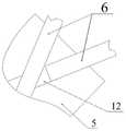
图2为本发明实施例的搭接在一起的两根超导带材的端头放在基板上时的俯视结构示意图。FIG. 2 is a schematic top view of the structure when the ends of two overlapping superconducting tapes are placed on a substrate according to an embodiment of the present invention.
图3为本发明实施例的锁紧壳的结构示意图。FIG. 3 is a schematic structural diagram of a locking shell according to an embodiment of the present invention.
具体实施方法Specific implementation method
实施例Example
如图1-图3示出,一种用于磁约束聚变磁体的高温超导带材串联接头,其特征在于:As shown in Figures 1-3, a series joint of high-temperature superconducting tapes for magnetic confinement fusion magnets is characterized by:
基板5上表面的一侧固定有“Г”型的支座8,支座8上部的横杆8a的端部为带内螺纹的固定环8b;One side of the upper surface of the
所述的固定环8b的内螺纹与加压轴1的外螺纹配合,加压轴1的下端穿出固定环8b与轴承2的内圈紧配合,轴承2的外圈固定在轴承座3上,且加压轴1的下端面高于轴承座3的下表面;所述的轴承座3通过定位销7依次与下方的压板4和基板5连接;所述的压板4和基板5间放置有搭接在一起的两根超导带材6的端头,且两根超导带材6的端头间还夹有铟片12。The inner thread of the
本例的加压轴1穿出固定环8b的上部设有拧转机构。In this example, the upper part of the pressing shaft 1 passing through the
本例的拧转机构的具体构成是:加压轴1的侧面开有拧转孔11,拧转杆插接或螺纹连接于拧转孔11内。The specific structure of the twisting mechanism in this example is as follows: a twisting
本例的轴承座3和压板4上设有连通的冷却液注入通孔10。The
本例的加压轴1上设有与轴承2内圈的上侧面接触的轴肩1a。The pressurizing shaft 1 of this example is provided with a shoulder 1a which is in contact with the upper surface of the inner ring of the
本例的加压轴1的上部外套有锁紧壳9,锁紧壳9的侧面开有用于插锁紧销的锁紧孔9a,且锁紧孔9a与拧转孔11对齐,锁紧壳9的侧面连有侧板9b;支座8上部的横杆8a上设有用于插横杆锁紧销的横杆锁紧孔8c,侧板9b上设有与横杆锁紧孔8c对齐的侧板锁紧孔9c。The upper casing of the pressing shaft 1 in this example is provided with a locking
Claims (6)
Priority Applications (1)
| Application Number | Priority Date | Filing Date | Title |
|---|---|---|---|
| CN202010817768.3ACN111933308B (en) | 2020-08-14 | 2020-08-14 | A series joint of high temperature superconducting tapes for magnetic confinement fusion magnets |
Applications Claiming Priority (1)
| Application Number | Priority Date | Filing Date | Title |
|---|---|---|---|
| CN202010817768.3ACN111933308B (en) | 2020-08-14 | 2020-08-14 | A series joint of high temperature superconducting tapes for magnetic confinement fusion magnets |
Publications (2)
| Publication Number | Publication Date |
|---|---|
| CN111933308Atrue CN111933308A (en) | 2020-11-13 |
| CN111933308B CN111933308B (en) | 2022-09-09 |
Family
ID=73310910
Family Applications (1)
| Application Number | Title | Priority Date | Filing Date |
|---|---|---|---|
| CN202010817768.3AActiveCN111933308B (en) | 2020-08-14 | 2020-08-14 | A series joint of high temperature superconducting tapes for magnetic confinement fusion magnets |
Country Status (1)
| Country | Link |
|---|---|
| CN (1) | CN111933308B (en) |
Citations (14)
| Publication number | Priority date | Publication date | Assignee | Title |
|---|---|---|---|---|
| DE19803687C1 (en)* | 1998-01-30 | 1999-11-25 | Siemens Ag | Soldering high-temperature superconductors of a cable to a connector piece |
| CN101692368A (en)* | 2009-09-30 | 2010-04-07 | 中国科学院等离子体物理研究所 | High-temperature superconductive magnet system for magnetically confined plasma propeller |
| US20100190649A1 (en)* | 2009-01-29 | 2010-07-29 | Doll David W | Low loss joint for superconducting wire |
| CN201711521U (en)* | 2010-06-24 | 2011-01-19 | 西北工业大学 | Strong pulse current directional solidifying device |
| CN102971914A (en)* | 2010-07-08 | 2013-03-13 | 英国西门子公司 | Superconducting joint cups and methods for cooling superconducting joints |
| JP2013175293A (en)* | 2012-02-23 | 2013-09-05 | Fujikura Ltd | Superconductive current lead, current lead device, and superconducting magnet device |
| CN104036914A (en)* | 2014-05-22 | 2014-09-10 | 中国科学院电工研究所 | Manufacturing method for high-temperature superconductivity strip connector of high-temperature superconductivity double-pancake coils |
| CN105637592A (en)* | 2013-09-13 | 2016-06-01 | 托卡马克能量有限公司 | Toroidal field coil for use in a fusion reactor |
| CN108766709A (en)* | 2018-06-13 | 2018-11-06 | 苏州新材料研究所有限公司 | High-temperature superconductor inside coil and preparation method thereof |
| CN208262072U (en)* | 2018-05-21 | 2018-12-21 | 西安聚能超导磁体科技有限公司 | A kind of welder of high-temperature superconductor band connector |
| JP2019040771A (en)* | 2017-08-25 | 2019-03-14 | 株式会社東芝 | Superconducting tape wire, superconducting current lead using this superconducting tape wire, permanent current switch, and superconducting coil |
| CN110111965A (en)* | 2019-05-09 | 2019-08-09 | 西南交通大学 | A kind of construction mixing superconducting magnet and the magnetic suspension bearing with it |
| CN111009377A (en)* | 2019-12-05 | 2020-04-14 | 西南交通大学 | A kind of preparation method of superconducting D-type coil for magnetic confinement fusion |
| CN111366879A (en)* | 2018-12-24 | 2020-07-03 | 核工业西南物理研究院 | Testing device and testing method for high-temperature superconducting strip and cable joint thereof |
- 2020
- 2020-08-14CNCN202010817768.3Apatent/CN111933308B/enactiveActive
Patent Citations (14)
| Publication number | Priority date | Publication date | Assignee | Title |
|---|---|---|---|---|
| DE19803687C1 (en)* | 1998-01-30 | 1999-11-25 | Siemens Ag | Soldering high-temperature superconductors of a cable to a connector piece |
| US20100190649A1 (en)* | 2009-01-29 | 2010-07-29 | Doll David W | Low loss joint for superconducting wire |
| CN101692368A (en)* | 2009-09-30 | 2010-04-07 | 中国科学院等离子体物理研究所 | High-temperature superconductive magnet system for magnetically confined plasma propeller |
| CN201711521U (en)* | 2010-06-24 | 2011-01-19 | 西北工业大学 | Strong pulse current directional solidifying device |
| CN102971914A (en)* | 2010-07-08 | 2013-03-13 | 英国西门子公司 | Superconducting joint cups and methods for cooling superconducting joints |
| JP2013175293A (en)* | 2012-02-23 | 2013-09-05 | Fujikura Ltd | Superconductive current lead, current lead device, and superconducting magnet device |
| CN105637592A (en)* | 2013-09-13 | 2016-06-01 | 托卡马克能量有限公司 | Toroidal field coil for use in a fusion reactor |
| CN104036914A (en)* | 2014-05-22 | 2014-09-10 | 中国科学院电工研究所 | Manufacturing method for high-temperature superconductivity strip connector of high-temperature superconductivity double-pancake coils |
| JP2019040771A (en)* | 2017-08-25 | 2019-03-14 | 株式会社東芝 | Superconducting tape wire, superconducting current lead using this superconducting tape wire, permanent current switch, and superconducting coil |
| CN208262072U (en)* | 2018-05-21 | 2018-12-21 | 西安聚能超导磁体科技有限公司 | A kind of welder of high-temperature superconductor band connector |
| CN108766709A (en)* | 2018-06-13 | 2018-11-06 | 苏州新材料研究所有限公司 | High-temperature superconductor inside coil and preparation method thereof |
| CN111366879A (en)* | 2018-12-24 | 2020-07-03 | 核工业西南物理研究院 | Testing device and testing method for high-temperature superconducting strip and cable joint thereof |
| CN110111965A (en)* | 2019-05-09 | 2019-08-09 | 西南交通大学 | A kind of construction mixing superconducting magnet and the magnetic suspension bearing with it |
| CN111009377A (en)* | 2019-12-05 | 2020-04-14 | 西南交通大学 | A kind of preparation method of superconducting D-type coil for magnetic confinement fusion |
Non-Patent Citations (5)
| Title |
|---|
| ANTHONY J. DIETZ 等: "Resistance of Demountable Mechanical Lap Joints for a High Temperature Superconducting Cable Connector", 《IEEE TRANSACTIONS ON APPLIED SUPERCONDUCTIVITY》* |
| YONG ZHAO 等: "Improvement of Superconducting Properties by Optimized Post-Heat Treatment for Nb3Al Wires Fabricated by RHQ", 《IEEE TRANSACTIONS ON APPLIED SUPERCONDUCTIVITY 》* |
| 刘伟 等: "高温超导带材多场特性测试系统研制进展(II)", 《试验力学》* |
| 诸嘉慧等: "一种新型YBCO高温超导带材临界电流特性测试方法", 《低温与超导》* |
| 邱添 等: "高温超导带材不同焊接接头长度对失超传播特性影响实验研究", 《低温物理学报》* |
Also Published As
| Publication number | Publication date |
|---|---|
| CN111933308B (en) | 2022-09-09 |
Similar Documents
| Publication | Publication Date | Title |
|---|---|---|
| CN102735902B (en) | High-temperature superconducting wire tensile force testing device | |
| CN105865919A (en) | Critical current test device for high-temperature superconducting strip under action of lateral compression | |
| CN209821330U (en) | High-temperature superconducting strip and testing device for cable joint thereof | |
| CN108871951B (en) | Stretch bending torsion comprehensive loading device for superconducting strip under low temperature and magnetic field | |
| CN101499350B (en) | Superconducting magnet framework | |
| CN113053613B (en) | A conduction-cooled high-temperature superconducting electric suspension magnet structure | |
| CN109148074A (en) | A kind of sub- cable bond superconducting joint of cylinder | |
| CN108106935A (en) | A kind of critical performance testing device of superconducting line axial strain | |
| CN106840867A (en) | The drawing by high temperature fatigue test clamper and method of a kind of flat test piece | |
| CN111933308B (en) | A series joint of high temperature superconducting tapes for magnetic confinement fusion magnets | |
| CN109285647B (en) | A liquid helium-immersed low-temperature superconducting component for high-current high-temperature superconducting current leads | |
| CN100485828C (en) | A cooling arrangement for high temperature superconducting device | |
| CN116642688A (en) | Performance testing method and device for ultra-high vacuum elastic energy storage metal sealing ring | |
| CN201689992U (en) | Combined high-temperature superconducting current lead | |
| Terazaki et al. | Measurement of the joint resistance of large-current YBCO conductors | |
| CN205607773U (en) | Critical current testing arrangement under horizontal compression of high -temperature superconducting tape | |
| CN201430139Y (en) | In-series thyristor valve section | |
| CN114937539B (en) | REBCO high temperature superconducting coil internal joint, welding device and preparation method | |
| CN220019848U (en) | Superconducting tape critical current testing device | |
| CN104037581A (en) | Fabrication device of high-temperature superconducting-band circular arc joint | |
| CN116520217A (en) | Testing device suitable for superconducting performance of REBCO double-pancake coil | |
| Wen et al. | Manufacture and behaviors of superconducting busbar joint for ITER correction coil feeder | |
| CN112986706B (en) | High-temperature superconducting tape mechanical connection testing device | |
| CN117912790B (en) | High-temperature superconducting magnet cold guide device with embedded cold guide tube | |
| CN2731650Y (en) | Flexible device of high temp supraconduction and direct coding |
Legal Events
| Date | Code | Title | Description |
|---|---|---|---|
| PB01 | Publication | ||
| PB01 | Publication | ||
| SE01 | Entry into force of request for substantive examination | ||
| SE01 | Entry into force of request for substantive examination | ||
| GR01 | Patent grant | ||
| GR01 | Patent grant |