CN111929918A - Nose pad subassembly and glasses - Google Patents
Nose pad subassembly and glassesDownload PDFInfo
- Publication number
- CN111929918A CN111929918ACN202010779877.0ACN202010779877ACN111929918ACN 111929918 ACN111929918 ACN 111929918ACN 202010779877 ACN202010779877 ACN 202010779877ACN 111929918 ACN111929918 ACN 111929918A
- Authority
- CN
- China
- Prior art keywords
- connecting rod
- nose
- pad assembly
- nose pad
- mounting hole
- Prior art date
- Legal status (The legal status is an assumption and is not a legal conclusion. Google has not performed a legal analysis and makes no representation as to the accuracy of the status listed.)
- Granted
Links
Images


Classifications
- G—PHYSICS
- G02—OPTICS
- G02C—SPECTACLES; SUNGLASSES OR GOGGLES INSOFAR AS THEY HAVE THE SAME FEATURES AS SPECTACLES; CONTACT LENSES
- G02C5/00—Constructions of non-optical parts
- G02C5/12—Nose pads; Nose-engaging surfaces of bridges or rims
- G02C5/122—Nose pads; Nose-engaging surfaces of bridges or rims with adjustable means
- G02C5/124—Nose pads; Nose-engaging surfaces of bridges or rims with adjustable means for vertically varying the position of the lenses
Landscapes
- Physics & Mathematics (AREA)
- Health & Medical Sciences (AREA)
- General Physics & Mathematics (AREA)
- Ophthalmology & Optometry (AREA)
- Optics & Photonics (AREA)
- Eyeglasses (AREA)
Abstract
Translated fromChinese
Description
Translated fromChinese技术领域technical field
本申请涉及穿戴式设备领域,特别涉及一种鼻托组件和眼镜。The present application relates to the field of wearable devices, and in particular, to a nose pad assembly and glasses.
背景技术Background technique
眼镜是很多用户都会有的可穿戴式设备,无论是矫正视力的眼镜还是装饰用的眼镜都需要鼻托和镜腿佩戴。其中,眼镜的鼻托往往是通过胶水或螺丝等工件固定在眼镜架上,无法对鼻托的高度进行调节,鼻托活动的自由度较低。Glasses are wearable devices that many users will have. Whether they are vision correction glasses or decorative glasses, nose pads and temples are required. Among them, the nose pads of the glasses are often fixed on the glasses frame by a workpiece such as glue or screws, the height of the nose pads cannot be adjusted, and the freedom of movement of the nose pads is low.
发明内容SUMMARY OF THE INVENTION
本申请实施例提供一种鼻托组件和眼镜,可以调整鼻托的高度。Embodiments of the present application provide a nose pad assembly and glasses, which can adjust the height of the nose pad.
本申请实施例提供一种鼻托组件,其用于设置在眼镜的眼镜架上,所述鼻托组件包括:An embodiment of the present application provides a nose pad assembly, which is used to be disposed on a spectacle frame of glasses, and the nose pad assembly includes:
支架,包括滑槽;Brackets, including chutes;
鼻架,包括滑块部和托叶,所述滑块部能够在所述滑槽内移动,并带动所述托叶移动;The nose frame includes a slider part and a stipule, and the slider part can move in the chute and drive the stipule to move;
第一连杆,与所述支架转动连接;以及a first link, rotatably connected to the bracket; and
第二连杆,与所述鼻架转动连接,所述第二连杆与所述第一连杆通过转轴连接,所述第一连杆通过所述转轴能够和所述第二连杆在多个角度之间调节,并带动所述鼻架的所述托叶移动。The second connecting rod is rotatably connected with the nose piece, the second connecting rod is connected with the first connecting rod through a rotating shaft, and the first connecting rod can be connected with the second connecting rod at multiple times through the rotating shaft. It can be adjusted between different angles, and the stipules of the nose frame are driven to move.
本申请实施例还提供一种眼镜,其包括:The embodiment of the present application also provides a kind of glasses, which includes:
眼镜架;以及eyeglass frames; and
鼻托组件,所述鼻托组件为上述所述的鼻托组件,所述鼻托组件的支架与所述眼镜架固定连接。The nose pad assembly is the above-mentioned nose pad assembly, and the bracket of the nose pad assembly is fixedly connected with the spectacle frame.
本申请实施例中,鼻架可以在支架的滑槽内移动,鼻架移动过程中,可以带动鼻架的托叶移动。第一连杆与支架转动连接,第二连杆与鼻架转动连接,第一连杆与第二连杆通过转轴连接,并且第一连杆通过转轴能够和第二连杆在多个角度之间调节,从而将托叶固定在多个位置,实现了托叶高度的动态调节,能满足不同用户的需求。In the embodiment of the present application, the nose piece can move in the chute of the bracket, and during the movement of the nose piece, the stipules of the nose piece can be driven to move. The first connecting rod is rotatably connected with the bracket, the second connecting rod is rotatably connected with the nose frame, the first connecting rod and the second connecting rod are connected by a rotating shaft, and the first connecting rod can be connected with the second connecting rod at multiple angles through the rotating shaft. The stipules are fixed in multiple positions, and the height of the stipules can be dynamically adjusted to meet the needs of different users.
附图说明Description of drawings
为了更清楚地说明本申请实施例中的技术方案,下面将对实施例描述中所需要使用的附图作简单地介绍。显而易见地,下面描述中的附图仅仅是本申请的一些实施例,对于本领域技术人员来讲,在不付出创造性劳动的前提下,还可以根据这些附图获得其他的附图。In order to illustrate the technical solutions in the embodiments of the present application more clearly, the following briefly introduces the accompanying drawings that are used in the description of the embodiments. Obviously, the drawings in the following description are only some embodiments of the present application, and for those skilled in the art, other drawings can also be obtained from these drawings without creative effort.
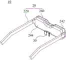
图1为本申请实施例提供的眼镜的第一种结构示意图。FIG. 1 is a schematic diagram of a first structure of glasses provided by an embodiment of the present application.
图2为图1所示眼镜的鼻托组件的示意图。FIG. 2 is a schematic diagram of the nose pad assembly of the glasses shown in FIG. 1 .
图3为图2所示鼻托组件的分解示意图。FIG. 3 is an exploded schematic view of the nose pad assembly shown in FIG. 2 .
图4为图2所示鼻托组件中第一连杆和第二连杆的结构示意图。FIG. 4 is a schematic structural diagram of the first connecting rod and the second connecting rod in the nose pad assembly shown in FIG. 2 .
图5为图4中第一连杆和第二连杆沿AA方向的截面示意图。FIG. 5 is a schematic cross-sectional view of the first connecting rod and the second connecting rod in the AA direction in FIG. 4 .
图6为图2所示鼻托组件中第二连杆的结构示意图。FIG. 6 is a schematic structural diagram of the second connecting rod in the nose pad assembly shown in FIG. 2 .
图7为图2所示鼻托组件中第一连杆的结构示意图。FIG. 7 is a schematic structural diagram of the first connecting rod in the nose pad assembly shown in FIG. 2 .
图8为图2所示鼻托组件中鼻架的结构示意图。FIG. 8 is a schematic structural diagram of the nose piece in the nose piece assembly shown in FIG. 2 .
图9为图2所示鼻托组件中支架的结构示意图。FIG. 9 is a schematic structural diagram of the bracket in the nose pad assembly shown in FIG. 2 .
图10为图2所述鼻托组件中鼻架和托叶位于中间位置的示意图。FIG. 10 is a schematic diagram of the nose frame and the stipules in the middle position of the nose pad assembly shown in FIG. 2 .
图11为图10所示鼻托组件的截面图。FIG. 11 is a cross-sectional view of the nose pad assembly shown in FIG. 10 .
图12为图2所述鼻托组件中鼻架和托叶位于最高位置的示意图。FIG. 12 is a schematic view of the nose frame and the stipules in the nose pad assembly shown in FIG. 2 at the highest position.
图13为图12所示鼻托组件的截面图。FIG. 13 is a cross-sectional view of the nose pad assembly shown in FIG. 12 .
图14为图2所述鼻托组件中鼻架和托叶位于最低位置的示意图。FIG. 14 is a schematic view of the nose frame and the stipules in the nose pad assembly shown in FIG. 2 in the lowest position.
图15为图14所示鼻托组件的截面图。FIG. 15 is a cross-sectional view of the nose pad assembly shown in FIG. 14 .
图16为图1所示眼镜中部分结构示意图。FIG. 16 is a schematic diagram of a part of the structure of the glasses shown in FIG. 1 .
图17为图1所示眼镜的正面示意图。FIG. 17 is a schematic front view of the glasses shown in FIG. 1 .
图18为图17中所示眼镜沿BB方向的截面示意图。FIG. 18 is a schematic cross-sectional view of the glasses shown in FIG. 17 along the BB direction.
图19为图18所示眼镜中X部分的放大示意图。FIG. 19 is an enlarged schematic view of part X of the glasses shown in FIG. 18 .
具体实施方式Detailed ways
下面将结合本申请实施例中的附图,对本申请实施例中的技术方案进行清楚、完整地描述。显然,所描述的实施例仅仅是本申请一部分实施例,而不是全部的实施例。基于本申请中的实施例,本领域技术人员在没有作出创造性劳动前提下所获得的所有其他实施例,都属于本申请保护的范围。The technical solutions in the embodiments of the present application will be clearly and completely described below with reference to the accompanying drawings in the embodiments of the present application. Obviously, the described embodiments are only a part of the embodiments of the present application, but not all of the embodiments. Based on the embodiments in the present application, all other embodiments obtained by those skilled in the art without creative work fall within the protection scope of the present application.
请参阅图1,图1为本申请实施例提供的眼镜的第一种结构示意图。眼镜10包括眼镜架20和鼻托组件30。眼镜架20包括镜框240和两条镜腿220,两条镜腿220用于挂设在用户的耳朵上,两条镜腿220分别与镜框240的两端连接,镜框240用于安装镜片。鼻托组件30设置在眼镜10的眼镜架20上,鼻托组件30与眼镜架20连接,或者说与眼镜架20的镜框240连接。鼻托组件30用于抵接用户的鼻梁,并与两条镜腿220共同支撑镜框240和镜片。Please refer to FIG. 1 . FIG. 1 is a schematic diagram of a first structure of glasses provided by an embodiment of the present application. The
需要说明的是,眼镜架可以根据需要选择其他结构,本申请实施例不对眼镜架的结构进行限定,即本申请实施例的眼镜架可以采用本领域已公开的任意一种眼镜架的结构。例如,眼镜架可以不设置镜腿,而是通过绑带固定。又例如,眼镜架的镜框可以不设置镜片,即眼镜作为装饰品。It should be noted that other structures of the spectacle frame may be selected as required, and the structure of the spectacle frame is not limited in the embodiments of the present application, that is, the spectacle frame of the embodiment of the present application may adopt any structure of the spectacle frame disclosed in the art. For example, the spectacle frame may not be provided with temples, but be fixed by straps. For another example, the frame of the spectacle frame may not be provided with lenses, that is, the spectacles are used as decorations.
随着5G时代的到来,智能眼镜越来越重要,其中,成年人中不同年龄阶段不同地域的人,其头部特征是不同的,人头顶到鼻尖点的距离偏差可达到9.6mm。智能眼镜穿戴需要鼻子辅助佩戴。不同用户需要的鼻托组件的高度不同,为了使得同一个智能眼镜可以给不同的用户使用,将眼镜的眼镜架和鼻托组件设置为可拆卸连接,并且提供多个不同高度的鼻托,用户可以根据自己的需要选择一个鼻托组件与眼镜架安装,以实现调节鼻托组件的高度。但是,提供多个不同高度鼻托会增加成本。而且对用户而言,只有一个鼻托组件是合适的,其他鼻托组件都不太合适,是多余的。另外,可拆卸安装的鼻托组件容易丢失,丢失的一般是最合适的鼻托组件,剩下的其他鼻托组件的高度并不适合用户,从而使整个眼镜都无法使用或者使用不方便。With the advent of the 5G era, smart glasses are becoming more and more important. Among adults, people of different ages and regions have different head characteristics, and the deviation of the distance from the top of the head to the tip of the nose can reach 9.6mm. Wearing smart glasses requires nose assistance. Different users need different heights of the nose pads. In order to make the same smart glasses available to different users, the glasses frame and the nose pads of the glasses are set to be detachably connected, and multiple nose pads of different heights are provided. You can choose a nose pad assembly to install with the glasses frame according to your own needs, so as to adjust the height of the nose pad assembly. However, providing multiple nose pads of different heights increases cost. Moreover, for the user, only one nose pad assembly is suitable, and the other nose pad assemblies are not suitable and are redundant. In addition, the detachably installed nose pad assemblies are easy to lose, and the most suitable nose pad assemblies are generally lost, and the height of the remaining nose pad assemblies is not suitable for the user, so that the entire glasses cannot be used or are inconvenient to use.
可以理解的,鼻托组件还可以采用其他结构。具体请结合图2和图3,图2为图1所示眼镜的鼻托组件的示意图,图3为图2所示鼻托组件的分解示意图。鼻托组件30包括支架320、鼻架340、第一连杆360和第二连杆380。支架320包括滑槽322。鼻架340包括滑块部342和托叶344,滑块部342能够在滑槽322内移动,并带动托叶344移动。第一连杆360与支架320转动连接。第二连杆380与鼻架340转动连接,第二连杆380与第一连杆360通过转轴370连接,第一连杆360通过转轴370能够和第二连杆380在多个角度之间调节,并带动鼻架340的托叶344移动。It can be understood that the nose pad assembly can also adopt other structures. For details, please refer to FIG. 2 and FIG. 3 . FIG. 2 is a schematic diagram of the nose pad assembly of the glasses shown in FIG. 1 , and FIG. 3 is an exploded schematic view of the nose pad assembly shown in FIG. 2 . The
鼻架340通过滑块部342可以在支架320的滑槽322内移动,并且鼻架340在移动过程中,可以带动鼻架340的托叶344移动。第一连杆360与第二连杆380通过转轴370连接,并且第一连杆360通过转轴370能够和第二连杆380在多个角度之间调节,从而将托叶344固定在多个位置,实现了托叶344高度的动态调节,能满足不同用户的需求。其中,转轴370能够使第一连杆360与第二连杆380在眼镜10的重力作用下保持在一定的角度,通过外力来改变第一连杆360与第二连杆380间的角度,从而实现鼻托可调节不同高度的功能。The
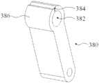
请结合图4至图6,图4为图2所示鼻托组件中第一连杆和第二连杆的结构示意图,图5为图4中第一连杆和第二连杆沿AA方向的截面示意图,图6为图2所示鼻托组件中第二连杆的结构示意图。转轴370与第一连杆360固定连接,第二连杆380开设有第二安装孔382,转轴370穿设于第二安装孔382,并与第二安装孔382过盈配合。Please refer to Figures 4 to 6. Figure 4 is a schematic structural diagram of the first link and the second link in the nose pad assembly shown in Figure 2, and Figure 5 is the first link and the second link in Figure 4 along the AA direction FIG. 6 is a schematic diagram of the structure of the second connecting rod in the nose pad assembly shown in FIG. 2 . The
其中,转轴370可以与第一连杆360粘结固定、热熔固定、螺接固定或卡接固定等方式实现固定连接。转轴370与第二安装孔382过盈配合,使转轴370与第二连杆380之间产生夹持摩擦力,从而使转轴370与第二连杆380在眼镜10的重力作用下可以保持在一固定的夹角,因为转轴370与第一连杆360固定连接,也可以理解为转轴370使第二连杆380与第一连杆360能够保持在一固定的夹角。Wherein, the
可以理解的,因为,第一连杆360与支架320转动连接,第二连杆380与鼻架340转动连接,鼻架340能在支架320的滑槽322内移动,所以,当鼻架340受外力作用做升降运动时,即当鼻架340在滑槽322内移动时,鼻架340带动第二连杆380运动,第二连杆380带动第一连杆360运动,使第一连杆360和第二连杆380之间的夹角a发生变化,如从a1变成a2。由于第二连杆380与转轴370过盈配合,第二连杆380与转轴370之间具有摩擦力,选择合适的过盈量,使得摩擦力大于眼镜10的重力也大于鼻架340的重力。当外力去除时,因为外力导致的第一连杆360和第二连杆380夹角a2不会改变,保持当前夹角a2不变,即可以保持鼻架340的托叶344当前高度不变。It can be understood that, because the
相关技术中,提供几个不同高度的鼻托,只能给用户提供相对高度适合的鼻托,而无法提供适配的最佳高度。而本实施例中,滑槽322的长度就是鼻架340的滑动范围,即托叶344的高度调节范围。用户可以根据需要在高度调节范围内,随意调整托叶344高度,而不仅限于有限的几个高度。本实施例的鼻托组件30可以实现无级调节,在高度调节范围内的任意高度都可以实现。能够满足不同年龄阶段以及不同地域的人的使用需求。而且,鼻托组件30与眼镜架20固定连接,没有掉落丢失的风险。In the related art, providing several nose pads with different heights can only provide the user with a nose pad with a relatively suitable height, but cannot provide an optimal height for adaptation. In this embodiment, the length of the
第二连杆380包括形成第二安装孔382的侧壁386,侧壁386开设有侧壁开口384,侧壁开口384与第二安装孔382连通。设有侧壁开口384的侧壁386更容易安装转轴370。其中,侧壁386包括相对的第一端和第二端,侧壁开口384从第一端延伸至第二端,即侧壁386具有一贯穿的侧壁开口384,侧壁386能够基于侧壁开口384往两侧拉开,即第二安装孔382能够张开变形,从而方便转轴370穿设于变大的第二安装孔382内。The
可以理解的,转轴可以为一长的转轴,转轴穿设于第二安装孔,转轴两端分别于第一连杆固定连接。转轴也可以为两个短的转轴,任意一个转轴一端与第一连杆固定连接,另一端设置于第二安装孔内。It can be understood that the rotating shaft may be a long rotating shaft, the rotating shaft is penetrated through the second installation hole, and the two ends of the rotating shaft are respectively fixedly connected to the first connecting rod. The rotating shaft can also be two short rotating shafts, one end of any one of the rotating shafts is fixedly connected with the first connecting rod, and the other end is arranged in the second installation hole.
请结合图7并参阅图4和图5,图7为图2所示鼻托组件中第一连杆的结构示意图。转轴370可以与第二连杆380固定连接,第一连杆360开设有第一安装孔362,转轴370穿设于第一安装孔362,并与第一安装孔362过盈配合。其中,转轴370可以与第二连杆380粘结固定、热熔固定、螺接固定或卡接固定等方式实现固定连接。转轴370与第一安装孔362过盈配合,使转轴370与第一连杆360之间产生夹持摩擦力,从而使转轴370与第一连杆360在眼镜10的重力作用下可以保持在一固定的夹角,因为转轴370与第二连杆380固定连接,也可以理解为转轴370使第二连杆380与第一连杆360能够保持在一固定的夹角。Please refer to FIG. 4 and FIG. 5 in conjunction with FIG. 7 . FIG. 7 is a schematic structural diagram of the first connecting rod in the nose pad assembly shown in FIG. 2 . The
可以理解的,因为,第一连杆360与支架320转动连接,第二连杆380与鼻架340转动连接,鼻架340能在支架320的滑槽322内移动,所以,当鼻架340受外力作用做升降运动时,即当鼻架340在滑槽322内移动时,鼻架340带动第二连杆380运动,第二连杆380带动第一连杆360运动,使第一连杆360和第二连杆380之间的夹角a发生变化,如从a1变成a2。由于第一连杆360与转轴370过盈配合,第一连杆360与转轴370之间具有摩擦力,选择合适的过盈量,使得摩擦力大于眼镜10的重力。当外力去除时,因为外力导致的第一连杆360和第二连杆380夹角a2不会改变,保持当前夹角a2不变,即可以保持鼻架340的托叶344当前高度不变。It can be understood that, because the
相关技术中,提供几个不同高度的鼻托,只能给用户提供相对高度适合的鼻托,而无法提供适配的最佳高度。In the related art, providing several nose pads with different heights can only provide the user with a nose pad with a relatively suitable height, but cannot provide an optimal height for adaptation.
而本实施例中,滑槽322的长度就是鼻架340的滑动范围,即托叶344的高度调节范围。用户可以根据需要在高度调节范围内,随意调整托叶344高度,而不仅限于有限的几个高度。本实施例的鼻托组件30可以实现无级调节,在高度调节范围内的任意高度都可以实现。能够满足不同年龄阶段以及不同地域的人的使用需求。而且,鼻托组件30与眼镜架20固定连接,没有掉落丢失的风险。In this embodiment, the length of the
第一连杆包括形成第一安装孔的侧壁,侧壁开设有缝隙,缝隙与第一安装孔连通。设有缝隙的侧壁更容易安装第二连杆。其中,侧壁包括相对的第一端和第二端,开口缝隙从第一端延伸至第二端,即侧壁的具有一贯穿的缝隙,侧壁能够基于缝隙往两侧拉开,即第一安装孔能够张开变形,从而方便转轴穿设于变大的第一安装孔内。The first connecting rod includes a side wall forming a first installation hole, the side wall is provided with a slit, and the slit communicates with the first installation hole. The side wall with the slit makes it easier to install the second link. Wherein, the side wall includes an opposite first end and a second end, and the opening slit extends from the first end to the second end, that is, the side wall has a penetrating slit, and the side wall can be pulled to both sides based on the slit, that is, the first An installation hole can be opened and deformed, so that the rotating shaft can be easily inserted into the enlarged first installation hole.
可以理解的,转轴可以为一长的转轴,转轴穿设于第一安装孔,转轴两端分别于第二连杆固定连接。转轴也可以为两个短的转轴,任意一个转轴一端与第二连杆固定连接,另一端设置于第一安装孔内。It can be understood that the rotating shaft may be a long rotating shaft, the rotating shaft passes through the first installation hole, and the two ends of the rotating shaft are respectively fixedly connected to the second connecting rod. The rotating shaft can also be two short rotating shafts, one end of any one of the rotating shafts is fixedly connected with the second connecting rod, and the other end is arranged in the first installation hole.
请继续参阅图2和图3,可以理解的,转轴370为阻尼转轴。阻尼转轴能够使第一连杆360和第二连杆380固定于多个角度。例如,当鼻架340受外力作用做升降运动时,即当鼻架340在滑槽322内移动时,鼻架340带动第二连杆380运动,第二连杆380带动第一连杆360运动,使第一连杆360和第二连杆380之间的夹角a发生变化,如从a1变成a2。当外力去除时,阻尼转轴370能够保持外力导致的第一连杆360和第二连杆380夹角a2不会改变,保持当前夹角a2不变,即可以保持鼻架340的托叶344当前高度不变。Please continue to refer to FIG. 2 and FIG. 3 , it can be understood that the
请结合图8和图9,图8为图2所示鼻托组件中鼻架的结构示意图,图9为图2所示鼻托组件中支架的结构示意图。鼻架340还包括主体部346和连接杆348,主体部346包括相对设置的第一端部3462和第二端部3464,第一端部3462两侧分别设有滑块部342,第二端部3464通过连接杆348连接托叶344。Please refer to FIG. 8 and FIG. 9 . FIG. 8 is a schematic structural diagram of a nose bridge in the nose pad assembly shown in FIG. 2 , and FIG. 9 is a structural schematic diagram of a bracket in the nose pad assembly shown in FIG. 2 . The
第一端部3462两侧的滑块部342能够沿滑槽322滑动,与第一端部3462相对设置的第二端部3464通过连接杆348连接托叶344,托叶344能够远离鼻托组件30和眼镜架20,托叶344能够抵接用户的鼻梁,使眼镜架20与鼻梁具有合适的距离,提高用户的佩戴舒适度。The
第一端部3462还设有第三安装孔347,鼻架340通过穿设于第三安装孔347的第一连接件330与第二连杆380转动连接。The
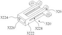
滑槽322包括相对设置的第一侧边3222和第二侧边3224,第一侧边3222和第二侧边3224均设有对应滑块部342的滑轨3226,第一侧边3222和第二侧边3224均设有侧边开口3228,第一连接件330的两端分别设置于一侧边开口3228内,并能够在侧边开口3228内移动。The sliding
滑块部342可以沿滑槽322的滑轨3226滑动,第一连接件330可以在侧边开口3228内移动,同时,滑槽322也限制了鼻架340的移动范围,防止鼻架340晃动,侧边开口3228也限制了第一连接件330的移动访问,防止第一连接件330和第二连杆380晃动。第一连接件可以为转轴或销钉等。The
支架320远离鼻架340的一端设有第四安装孔326,支架320通过穿设于第四安装孔326的第二连接件350与第一连杆360转动连接。支架320通过第二连接件350与第一连杆360转动。第二连接件可以为转轴或销钉等。The end of the
可以理解的,参阅图10至图15,图10为图2鼻托组件中鼻架和托叶位于中间位置的示意图,图11为图10所示鼻托组件的截面图,图12为图2鼻托组件中鼻架和托叶位于最高位置的示意图,图13为图12所示鼻托组件的截面图,图14为图2鼻托组件中鼻架和托叶位于最低位置的示意图,图15为图14所示鼻托组件的截面图。可以理解的,鼻架340和托叶的位置可以根据鼻架340在滑槽的位置对应调整。示例性地,当用户手动调整托叶或者鼻架340的位置时,即用户施加一个外力驱动托叶或鼻架340移动,托叶或鼻架340移动并带动第二连杆380移动,第二连杆380通过转轴370可以相对第一连杆360转动,并改变第一连杆360和第二连杆380的夹角。当用户撤去外力时,因为转轴370与第二连杆380过盈配合,转轴370与第二连杆380的摩擦力大于眼镜的重力,同时也大于鼻架340等的重力,转轴370和第二连杆380可以保持当前状态,即第一连杆360和第二连杆380可以保持当前的夹角,即鼻架340和托叶也可以保持在当前位置,即保持在被用户调整后的位置。It can be understood that referring to FIGS. 10 to 15 , FIG. 10 is a schematic diagram of the nose bridge and the stipules in the middle position of the nose pad assembly in FIG. 2 , FIG. 11 is a cross-sectional view of the nose pad assembly shown in FIG. 10 , and FIG. 12 is FIG. 2 Figure 13 is a cross-sectional view of the nose pad assembly shown in Figure 12, Figure 14 is a schematic diagram of the nose frame and the stipules in the lowest position in the nose pad assembly of Figure 2. 15 is a cross-sectional view of the nose pad assembly shown in FIG. 14 . It can be understood that the positions of the
请参阅图16并结合图1,图16为图1所示眼镜中部分结构示意图。其中,鼻托组件30的支架与眼镜架240固定连接。支架上设有螺丝孔,支架通过穿设于螺丝孔内的螺丝与眼镜架240固定连接。当然,支架还可以采用其他方式与眼镜架固定连接,如卡接固定连接、热熔固定连接、粘结固定连接等。在此不限定支架和眼镜架固定连接的方式。Please refer to FIG. 16 in conjunction with FIG. 1 . FIG. 16 is a schematic diagram of a part of the structure of the glasses shown in FIG. 1 . Wherein, the bracket of the
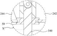
眼镜可以为智能眼镜,眼镜内还设有电路板,电路板上集成有功能模块,功能模块能够实现导航、语音通话、语音控制等功能。请结合图17至图19,图17为图1所示眼镜的正面示意图,图18为图17中所示眼镜沿BB方向的截面示意图,图19为图18所示眼镜中X部分的放大示意图。对应的,眼镜架240包括第一壳体242和第二壳体244,鼻托组件的支架设置于眼镜架240内,并与第一壳体242或第二壳体244固定连接;眼镜10还包括防水圈50,防水圈50套设于鼻架340,防水圈50设置于第一壳体242和第二壳体244之间。防水圈50可以防止外界的液体和灰尘等物质进入眼镜内部,起到防尘防水的功能。防水圈可以采用硅胶、塑胶、塑料等防水材料制成。The glasses can be smart glasses, and the glasses are further provided with a circuit board, and a functional module is integrated on the circuit board, and the functional module can realize functions such as navigation, voice call, and voice control. 17 to 19, FIG. 17 is a schematic front view of the glasses shown in FIG. 1, FIG. 18 is a schematic cross-sectional view of the glasses shown in FIG. 17 along the BB direction, and FIG. 19 is an enlarged schematic view of the X part of the glasses shown in FIG. 18 . Correspondingly, the
眼镜可以作为移动终端的可视化智能辅助设备,如眼镜可以展示时间、天气、运动步数等信息给用户,具体的可以通过眼镜的镜片显示并展示给用户。眼镜还可以提供到站提醒、定时闹钟、语音电话、待办事项提醒等功能,用户可以不握持移动终端而是通过眼镜获取即时消息、接听语音电话等,移动终端可以一直放置在口袋或包包里,不需要拿出来进行操作。还可以通过眼镜获取移动终端的显示界面,如移动终端的主界面、通知栏、应用程序界面等。Glasses can be used as visual intelligent auxiliary equipment for mobile terminals. For example, glasses can display information such as time, weather, and exercise steps to users. Specifically, they can be displayed and displayed to users through the lenses of glasses. The glasses can also provide functions such as arrival reminder, timed alarm clock, voice call, and to-do reminder. Users can obtain instant messages, answer voice calls, etc. through the glasses without holding the mobile terminal. The mobile terminal can always be placed in a pocket or bag. In the bag, no need to take it out to operate. The display interface of the mobile terminal, such as the main interface, notification bar, application program interface, etc. of the mobile terminal, can also be obtained through the glasses.
眼镜上可以集成语音模块,语音模块可以实现语音识别和语音控制功能,如根据语音控制眼镜的显示,获取语音并实施翻译功能(方便用户与外国人交流),还可以播放音频(如音乐、广播等)。The voice module can be integrated on the glasses, and the voice module can realize voice recognition and voice control functions, such as controlling the display of the glasses according to the voice, obtaining the voice and implementing the translation function (convenient for users to communicate with foreigners), and can also play audio (such as music, radio Wait).
眼镜上还可以集成定位模块,眼镜可以根据定位模块实现导航功能,并将导航信息如地图或道路指引等显示在镜片上,还可以和实景图像叠加,实现增加现实显示功能。用户不需要在低头看移动终端,可以根据镜片显示的导航信息行进。此外,还可以通过语音拨快播放导航语音,辅助导航。A positioning module can also be integrated on the glasses, and the glasses can realize the navigation function according to the positioning module, and display the navigation information such as maps or road directions on the lenses, and can also be superimposed with the real image to realize the increase of the real display function. The user does not need to look down at the mobile terminal, and can travel according to the navigation information displayed by the lens. In addition, you can also play the navigation voice through the voice dial to assist the navigation.
眼镜上还可以集成触控模块,可以通过触控模块控制眼镜的功能模块。如接听语音电话、关闭闹钟、调节音量等。A touch module can also be integrated on the glasses, and the functional modules of the glasses can be controlled through the touch module. Such as answering voice calls, turning off the alarm clock, adjusting the volume, etc.
眼镜的镜片可以为太阳镜镜片,眼镜不仅具有较强的智能功能,还具有较好的外观和实用性。可以理解的,当镜片可以实现显示功能时,镜片可以为特质的镜片,如叠加超薄高透光柔性显示屏。The lenses of the glasses can be sunglasses lenses, and the glasses not only have strong intelligent functions, but also have better appearance and practicability. It can be understood that when the lens can realize the display function, the lens can be a special lens, such as superimposing an ultra-thin and high-transmittance flexible display screen.
在本申请的描述中,术语“第一”、“第二”仅用于描述目的,而不能理解为指示或暗示相对重要性或者隐含指明所指示的技术特征的数量。由此,限定有“第一”、“第二”的特征可以明示或者隐含地包括一个或者更多个特征。在本申请的描述中,“多个”的含义是两个或两个以上,除非另有明确具体的限定。In the description of this application, the terms "first" and "second" are only used for descriptive purposes, and cannot be understood as indicating or implying relative importance or implying the number of indicated technical features. Thus, features defined as "first", "second" may expressly or implicitly include one or more features. In the description of the present application, "plurality" means two or more, unless otherwise expressly and specifically defined.
以上对本申请实施例提供的鼻托组件及眼镜进行了详细介绍。本文中应用了具体个例对本申请的原理及实施方式进行了阐述,以上实施例的说明只是用于帮助理解本申请。同时,对于本领域的技术人员,依据本申请的思想,在具体实施方式及应用范围上均会有改变之处,综上所述,本说明书内容不应理解为对本申请的限制。The nose pad assembly and the glasses provided in the embodiments of the present application are described in detail above. The principles and implementations of the present application are described herein by using specific examples, and the descriptions of the above embodiments are only used to help the understanding of the present application. At the same time, for those skilled in the art, according to the idea of the present application, there will be changes in the specific embodiments and application scope. To sum up, the content of this specification should not be construed as a limitation to the present application.
Claims (11)
Priority Applications (1)
| Application Number | Priority Date | Filing Date | Title |
|---|---|---|---|
| CN202010779877.0ACN111929918B (en) | 2020-08-05 | 2020-08-05 | Nose pad subassembly and glasses |
Applications Claiming Priority (1)
| Application Number | Priority Date | Filing Date | Title |
|---|---|---|---|
| CN202010779877.0ACN111929918B (en) | 2020-08-05 | 2020-08-05 | Nose pad subassembly and glasses |
Publications (2)
| Publication Number | Publication Date |
|---|---|
| CN111929918Atrue CN111929918A (en) | 2020-11-13 |
| CN111929918B CN111929918B (en) | 2022-06-14 |
Family
ID=73306791
Family Applications (1)
| Application Number | Title | Priority Date | Filing Date |
|---|---|---|---|
| CN202010779877.0AActiveCN111929918B (en) | 2020-08-05 | 2020-08-05 | Nose pad subassembly and glasses |
Country Status (1)
| Country | Link |
|---|---|
| CN (1) | CN111929918B (en) |
Cited By (1)
| Publication number | Priority date | Publication date | Assignee | Title |
|---|---|---|---|---|
| CN115808789A (en)* | 2021-09-15 | 2023-03-17 | Oppo广东移动通信有限公司 | Frame, wear support and head-mounted equipment |
Citations (5)
| Publication number | Priority date | Publication date | Assignee | Title |
|---|---|---|---|---|
| US5170502A (en)* | 1990-08-23 | 1992-12-15 | Uvex Winter Optical, Inc. | Protective eyewear assembly |
| WO2000026714A1 (en)* | 1998-10-30 | 2000-05-11 | Agilent Technologies, Inc. | Articulated nose bridge for head mounted display |
| US20020067461A1 (en)* | 2000-12-06 | 2002-06-06 | Bell John Louis | Neck-saver eyeglass frames for bi-focals |
| US7591555B1 (en)* | 2008-09-02 | 2009-09-22 | Lin Yun Chen | Framework of combination of spectacle frames with lenses |
| CN202583611U (en)* | 2011-10-15 | 2012-12-05 | 付祖家 | Nose support height adjustable mirror bracket |
- 2020
- 2020-08-05CNCN202010779877.0Apatent/CN111929918B/enactiveActive
Patent Citations (5)
| Publication number | Priority date | Publication date | Assignee | Title |
|---|---|---|---|---|
| US5170502A (en)* | 1990-08-23 | 1992-12-15 | Uvex Winter Optical, Inc. | Protective eyewear assembly |
| WO2000026714A1 (en)* | 1998-10-30 | 2000-05-11 | Agilent Technologies, Inc. | Articulated nose bridge for head mounted display |
| US20020067461A1 (en)* | 2000-12-06 | 2002-06-06 | Bell John Louis | Neck-saver eyeglass frames for bi-focals |
| US7591555B1 (en)* | 2008-09-02 | 2009-09-22 | Lin Yun Chen | Framework of combination of spectacle frames with lenses |
| CN202583611U (en)* | 2011-10-15 | 2012-12-05 | 付祖家 | Nose support height adjustable mirror bracket |
Cited By (1)
| Publication number | Priority date | Publication date | Assignee | Title |
|---|---|---|---|---|
| CN115808789A (en)* | 2021-09-15 | 2023-03-17 | Oppo广东移动通信有限公司 | Frame, wear support and head-mounted equipment |
Also Published As
| Publication number | Publication date |
|---|---|
| CN111929918B (en) | 2022-06-14 |
Similar Documents
| Publication | Publication Date | Title |
|---|---|---|
| TWI575252B (en) | Wearable device with input and output structures | |
| US9766482B2 (en) | Wearable device with input and output structures | |
| CN103748501B (en) | Wearable device with input and output structures | |
| US7798638B2 (en) | Eyeglasses with integrated video display | |
| JP6513573B2 (en) | Spectacles with concealed and invisible optics | |
| JP4141828B2 (en) | Glasses holding system | |
| US9429772B1 (en) | Eyeglass frame with input and output functionality | |
| JP2015509209A (en) | Wearable device with input / output mechanism | |
| US9696566B2 (en) | Spectacle with invisible optics | |
| US10950217B1 (en) | Acoustic quadrupole system for head mounted wearable device | |
| US20020093622A1 (en) | Flip-up eyewear | |
| JP2014502732A (en) | Adjustable glasses, lenses and frames | |
| CN111929918B (en) | Nose pad subassembly and glasses | |
| US20150163934A1 (en) | Mobile phone housing with tool frame | |
| US11409130B1 (en) | Spring hinge with accommodation for flexible printed circuit | |
| CN104166246B (en) | A kind of multifunctional glasses rack | |
| CN216145034U (en) | Wearable devices and their wearables | |
| CN210920677U (en) | Folding support | |
| CN212569295U (en) | Can adjust wireless VR glasses of lens | |
| CN207976793U (en) | Show equipment | |
| CN211928335U (en) | Wearable device | |
| CN210155418U (en) | A friction-fixed AR glasses | |
| EP1598691A1 (en) | Eyewear comprising multimedia device and multimedia device to be mounted on eyewear |
Legal Events
| Date | Code | Title | Description |
|---|---|---|---|
| PB01 | Publication | ||
| PB01 | Publication | ||
| SE01 | Entry into force of request for substantive examination | ||
| SE01 | Entry into force of request for substantive examination | ||
| GR01 | Patent grant | ||
| GR01 | Patent grant |