CN111926700A - UWB-based bridge cable defect detection positioning system and method - Google Patents
UWB-based bridge cable defect detection positioning system and methodDownload PDFInfo
- Publication number
- CN111926700A CN111926700ACN202010872070.1ACN202010872070ACN111926700ACN 111926700 ACN111926700 ACN 111926700ACN 202010872070 ACN202010872070 ACN 202010872070ACN 111926700 ACN111926700 ACN 111926700A
- Authority
- CN
- China
- Prior art keywords
- robot
- cable
- uwb
- detection
- base station
- Prior art date
- Legal status (The legal status is an assumption and is not a legal conclusion. Google has not performed a legal analysis and makes no representation as to the accuracy of the status listed.)
- Granted
Links
Images


Classifications
- E—FIXED CONSTRUCTIONS
- E01—CONSTRUCTION OF ROADS, RAILWAYS, OR BRIDGES
- E01D—CONSTRUCTION OF BRIDGES, ELEVATED ROADWAYS OR VIADUCTS; ASSEMBLY OF BRIDGES
- E01D19/00—Structural or constructional details of bridges
- E01D19/10—Railings; Protectors against smoke or gases, e.g. of locomotives; Maintenance travellers; Fastening of pipes or cables to bridges
- E01D19/106—Movable inspection or maintenance platforms, e.g. travelling scaffolding or vehicles specially designed to provide access to the undersides of bridges
- G—PHYSICS
- G01—MEASURING; TESTING
- G01N—INVESTIGATING OR ANALYSING MATERIALS BY DETERMINING THEIR CHEMICAL OR PHYSICAL PROPERTIES
- G01N21/00—Investigating or analysing materials by the use of optical means, i.e. using sub-millimetre waves, infrared, visible or ultraviolet light
- G01N21/84—Systems specially adapted for particular applications
- G01N21/88—Investigating the presence of flaws or contamination
- G01N21/8851—Scan or image signal processing specially adapted therefor, e.g. for scan signal adjustment, for detecting different kinds of defects, for compensating for structures, markings, edges
Landscapes
- General Health & Medical Sciences (AREA)
- General Physics & Mathematics (AREA)
- Pathology (AREA)
- Immunology (AREA)
- Analytical Chemistry (AREA)
- Engineering & Computer Science (AREA)
- Physics & Mathematics (AREA)
- Health & Medical Sciences (AREA)
- Biochemistry (AREA)
- Chemical & Material Sciences (AREA)
- Life Sciences & Earth Sciences (AREA)
- Architecture (AREA)
- Signal Processing (AREA)
- Computer Vision & Pattern Recognition (AREA)
- Structural Engineering (AREA)
- Civil Engineering (AREA)
- Investigating Materials By The Use Of Optical Means Adapted For Particular Applications (AREA)
Abstract
Translated fromChinese
Description
Translated fromChinese技术领域technical field
本发明属探伤机器人定位技术领域,具体来说,涉及基于UWB的桥梁拉索缺陷检测定位系统及方法。The invention belongs to the technical field of flaw detection robot positioning, and in particular relates to a UWB-based bridge cable defect detection and positioning system and method.
背景技术Background technique
经济的快速发展,桥梁有着越来越重要的意义。经济发展的同时,桥梁的建造技术也在不断提升。桥梁也逐渐从以前的木桥、石桥转变为现在的钢筋混泥土桥以及钢架桥。桥梁的功能也越来越多种多样,有城市内的立交桥,跨江大桥,跨山大桥,跨海大桥。桥梁的变化使我们的生活越来越便利。越来越高潮的建桥技术使大跨度桥梁层出不穷。其中,斜拉桥作为一种拉索体系,比梁式桥具有更大的跨越能力,而且造型优美,经济,是大跨度桥梁的最首选方案。With the rapid economic development, bridges have become more and more important. At the same time of economic development, the construction technology of bridges is also constantly improving. The bridges have also gradually changed from the previous wooden bridges and stone bridges to the current reinforced concrete bridges and steel frame bridges. The functions of bridges are becoming more and more diverse, including city overpasses, river-crossing bridges, mountain-crossing bridges, and sea-crossing bridges. Changes in bridges make our lives more and more convenient. The increasingly high-end bridge construction technology makes long-span bridges emerge one after another. Among them, cable-stayed bridges, as a kind of cable system, have greater spanning capacity than girder bridges, and are beautiful and economical, and are the most preferred solution for long-span bridges.
要由受压的桥塔、受拉的索和承弯的梁体组成。在斜拉索的正常工作中,斜拉索会受到桥面动载荷、风雨振、日照以及腐蚀性气体的反复作用,很容易发生外层护套破损,局部钢丝锈蚀等病害。斜拉索护套的损坏导致内部钢丝暴露在空气中,还有的斜拉索表面附着有油污可能渗透到索内部,加速钢丝的腐蚀,若不定期维护,最终会因钢丝腐蚀失效导致斜拉索失效甚至桥面坍塌等事故。It should be composed of pylons under compression, cables under tension and beams under bending. During the normal operation of the stay cable, the stay cable will be subjected to repeated action of the bridge deck dynamic load, wind and rain vibration, sunlight and corrosive gases, and it is easy to cause damage to the outer sheath, local steel wire corrosion and other diseases. The damage to the sheath of the stay cable leads to the exposure of the inner steel wire to the air, and the surface of some stay cables has oil stains that may penetrate into the interior of the cable and accelerate the corrosion of the steel wire. Accidents such as cable failure or even bridge deck collapse.
测机器人属于高空作业机器人,有效的代替了人工检测。目前拉索机器人的精确定位以及拉索缺陷识别定位依旧是机器人应用过程中的重点和难点。单纯的依靠电机编码器的里程信息产生过大的累计误差,不利于精确定位。The inspection robot belongs to the aerial work robot, which effectively replaces the manual inspection. At present, the precise positioning of the cable robot and the identification and positioning of cable defects are still the key and difficult points in the application process of the robot. Simply relying on the mileage information of the motor encoder produces excessive cumulative error, which is not conducive to accurate positioning.
发明内容SUMMARY OF THE INVENTION
解决上述问题,本发明公开了基于UWB的桥梁拉索缺陷检测定位系统及方法,解决拉索检测机器人运行过程中的定位问题,提高拉索缺陷定位精度。To solve the above problems, the present invention discloses a UWB-based bridge cable defect detection and positioning system and method, which solves the positioning problem during the operation of the cable detection robot and improves the cable defect positioning accuracy.
本发明的目的在于提供基于UWB的桥梁拉索缺陷检测定位系统及方法,解决拉索检测机器人运行过程中的定位问题,提高拉索缺陷定位精度。The purpose of the present invention is to provide a UWB-based bridge cable defect detection and positioning system and method, so as to solve the positioning problem during the operation of the cable detection robot and improve the positioning accuracy of the cable defect.
技术方案:为解决上述技术问题,本发明采用如下的技术方案:Technical scheme: in order to solve the above-mentioned technical problems, the present invention adopts the following technical scheme:
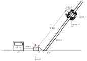
基于UWB的桥梁拉索检测机器人和拉索缺陷定位系统,该定位系统包括用于桥梁拉索的检测机器人、里程编码器、四个检测相机、图像分割器、图传单元、远程主机、UWB基站、机器人定位标签,编码器安装在检测机器人驱动轮上,UWB基站安装在待测拉索最低端,机器人定位标签安装于检测机器人,远程主机用于机器人控制和接收处理图像。UWB-based bridge cable inspection robot and cable defect positioning system, the positioning system includes inspection robot for bridge cable, mileage encoder, four inspection cameras, image divider, image transmission unit, remote host, UWB base station , Robot positioning label, the encoder is installed on the driving wheel of the detection robot, the UWB base station is installed at the lowest end of the cable to be tested, the robot positioning label is installed on the detection robot, and the remote host is used for robot control and receiving and processing images.
基于UWB的桥梁拉索检测机器人和拉索缺陷定位方法,具体流程包括;UWB-based bridge cable detection robot and cable defect location method, the specific process includes;
步骤(1):所述的UWB基站固定在拉索末端位置,开启拉索检测机器人,开启远程主机,等待系统初始化完成,测量机器人初始位置D0。Step (1): The UWB base station is fixed at the end position of the cable, the cable detection robot is turned on, the remote host is turned on, and the initial position D0 of the robot is measured after the system initialization is completed.
步骤(2):所述UWB基站和机器人定位标签之间多次进行高频脉冲的发送和反馈,获取飞行时间TOF并计算检测机器人相对于UWB基站的距离Dt,并发送给远程数据。Step (2): Send and feedback high-frequency pulses between the UWB base station and the robot positioning tag for many times, obtain the TOF of flight time, calculate the distance Dt of the detection robot relative to the UWB base station, and send remote data.
步骤(3):所述检测机器人通过电机驱动在待测拉索上运行,电机编码器记录电机转过的圈数,计算检测机器人的里程Dtc和速度Vtc。步骤(4):所述四个检测相机获取拉索当前位置360度图像,并合成一张图像发送给远程主机。Step (3): The detection robot is driven by the motor to run on the cable to be tested, and the motor encoder records the number of revolutions the motor rotates, and calculates the mileage Dtc and the speed Vtc of the detection robot. Step (4): The four detection cameras acquire a 360-degree image of the current position of the cable, and synthesize one image and send it to the remote host.
步骤(5):远程主机通过卡尔曼滤波算法对步骤(2)中所述的距离Dt进行最优估计得到Dt(es)。Step (5): The remote host performs optimal estimation on the distance Dt described in step (2) through the Kalman filter algorithm to obtain Dt(es) .
步骤(6):使用多传感器数据融合(卡尔曼融合算法或多贝叶斯估计法)对步骤(5)的距离Dt(es)和步骤(3)的里程数据Dtc,对检测机器人当前拉索位置进行估计,得到位置数据Dt(ESL);Step (6): Use multi-sensor data fusion (Kalman fusion algorithm or multi-Bayesian estimation method) to measure the distance Dt(es) of step (5) and the mileage data Dtc of step (3) to detect the current state of the robot. Estimate the position of the cable to obtain the position data Dt(ESL) ;
步骤(7):远程主机通过图像识别完成拉索缺陷图像识别,并在拉索图像上增加拉索位置数据Dt(ESL),用于缺陷定位。后回到步骤二,对检测机器人下一时刻进行定位。Step (7): The remote host completes the cable defect image recognition through image recognition, and adds the cable position data Dt(ESL) to the cable image for defect location. Then go back to
进一步,所述的定位系统和方法中步骤(2)的具体过程为:Further, the specific process of step (2) in the described positioning system and method is:
步骤(201)UWB基站发送脉冲信号,并记录当前时间t1;Step (201) the UWB base station sends a pulse signal and records the current time t1 ;
步骤(202)经过一定时间后,机器人定位标签接收信号并记录时间t2并在Treply_ROB时间后发送反馈信号;Step (202) After a certain period of time, the robot positioning tag receives the signal and records the time t2 and sends the feedback signal after the Treply_ROB time;
步骤(203)经过一定时间后,基站接受信号并记录当前t3时间后经过Treply_BS时间发送信号;Step (203) After a certain period of time, the base station receives the signal and records the currentt3 time and sends the signal after the Treply_BS time;
步骤(204)机器人定位标签接受信号并记录时间t4;Step (204) the robot positioning label receives the signal and records the time t4 ;
步骤(205)记录Tround_BS=t3-t1,Tround_ROB=t4-t2,根据DS-TWR算法计算信号飞行时间TOF:Step (205) records Tround_BS = t3 -t1 , Tround_ROB = t4 -t2 , and calculates the signal flight time TOF according to the DS-TWR algorithm:

步骤(206)根据Dt=C*TOF计算机器人标签和UWB基站位置Dt,C为光速,大小为3*108m/sStep (206) Calculate the robot tag and UWB base station position Dt according to Dt =C*TOF, where C is the speed of light and the size is 3*108 m/s
进一步,所述的定位系统和方法中步骤(5)的具体过程为:Further, the specific process of step (5) in the described positioning system and method is:
步骤(501)对用于位置估计的卡尔曼滤波参数进行相关初始化,包括协方差矩阵P′和过程噪音;Step (501) performs correlation initialization on Kalman filter parameters used for position estimation, including covariance matrix P' and process noise;
步骤(502)读取UWB在上一时刻的估计的数据Dt-1(es)(初始时刻为D0),机器人当前位置预测方程为:x′=x+vΔt具体为:Step (502) reads the estimated data Dt-1(es) of the UWB at the last moment (the initial moment is D0 ), and the prediction equation of the current position of the robot is: x′=x+vΔt is specifically:

其中:当前机器人状态为x,机器人速度为vx,时间间隔为Δt,且关系为:Among them: the current robot state is x, the robot speed is vx , the time interval is Δt, and the relationship is:

步骤(503)根据UWB测量数据Dt,以及观测方程为:
K=P′HT(HP′HT+R)-1,其中R为噪声矩阵K=P'HT (HP'HT +R)-1 , where R is the noise matrix

步骤(504)根据Pk=(I-KH)P′,对卡尔曼滤波的协方差更新,返回步骤(501)。Step (504) updates the covariance of the Kalman filter according to Pk =(I-KH)P', and returns to step (501).
进一步,所述的定位系统和方法中步骤(6)的中里程的观测方程为:
1、进一步,四个检测相机安装在机器人四周用于获取拉索表面360度图像,通过图像分割器把四张图片合称为一张,经过图传单元发送给远程主机进行识别处理。所述检测机器人的四个检测相机安装在机器人四周并根据公式:1. Further, four detection cameras are installed around the robot to obtain 360-degree images of the cable surface. The four images are collectively called one through the image divider, and sent to the remote host for identification processing through the image transmission unit. The four inspection cameras of the inspection robot are installed around the robot and according to the formula:

检测相机和待测拉索间的距离d,Detect the distance d between the camera and the cable to be tested,
通过调整相机和待测拉索距离保证既可以对拉索360度无盲区照射,又确保拉索在图像的比例大于50%,通过图像分割器把四张图片合称为一张,经过图传单元发送给远程主机进行识别处理。By adjusting the distance between the camera and the cable to be tested, it is ensured that the cable can be irradiated 360 degrees without blind spots, and that the proportion of the cable in the image is greater than 50%. Meta is sent to the remote host for identification processing.
有益效果:与现有技术相比,本发明的技术方案具有以下有益效果:Beneficial effects: Compared with the prior art, the technical scheme of the present invention has the following beneficial effects:
(1)通过UWB技术实现拉索检测机器人在拉索上距离的测定,并通过最优估计算来提高定位精度。(1) The distance measurement of the cable detection robot on the cable is realized by UWB technology, and the positioning accuracy is improved through the optimal estimation calculation.
(2)拉索机器人四摄像头的图像合成,提供图像检测的效率并减少误差,结合定位数据可以精确标记缺陷在拉索上的位置。(2) The image synthesis of the four cameras of the cable robot provides the efficiency of image detection and reduces errors. Combined with the positioning data, the position of the defect on the cable can be accurately marked.
(3)融合了里程信号和UWB定位数据的位置估计方式,进一步提高了拉索检测机器人定位精度。(3) The position estimation method which integrates the mileage signal and UWB positioning data, further improves the positioning accuracy of the cable detection robot.
附图说明Description of drawings
图1为本发明基于UWB的桥梁拉索拉索缺陷定位方法的流程图。FIG. 1 is a flow chart of the method for locating defects of bridge cables and cables based on UWB according to the present invention.
图2为本发明基于UWB的桥梁拉索缺陷定位系统示意图。FIG. 2 is a schematic diagram of the UWB-based bridge cable defect location system of the present invention.
图3为本发明基于UWB的桥梁拉索缺陷定位系统的架构图。FIG. 3 is an architectural diagram of the UWB-based bridge cable defect location system of the present invention.
图4为本发明中UWB的TOF计算的时间图。FIG. 4 is a time chart of TOF calculation of UWB in the present invention.
图5为本发明UWB定位数据和卡尔曼滤波后的对比图。FIG. 5 is a comparison diagram of UWB positioning data and Kalman filtering of the present invention.
具体实施方式Detailed ways
下面结合附图和具体实施方式,进一步阐明本发明,应理解下述具体实施方式仅用于说明本发明而不用于限制本发明的范围。需要说明的是,下面描述中使用的词语“前”、“后”、“左”、“右”、“上”和“下”指的是附图中的方向,词语“内”和“外”分别指的是朝向或远离特定部件几何中心的方向。The present invention will be further clarified below with reference to the accompanying drawings and specific embodiments. It should be understood that the following specific embodiments are only used to illustrate the present invention and not to limit the scope of the present invention. It should be noted that the words "front", "rear", "left", "right", "upper" and "lower" used in the following description refer to the directions in the drawings, and the words "inner" and "outer" ” refer to directions towards or away from the geometric center of a particular part, respectively.
如图1、2、3所示,本实施例提供基于UWB的桥梁拉索缺陷定位系统及方法,该定位系统包括用于桥梁拉索的检测机器人、里程编码器、四个检测相机、图像分割器、图传单元、远程主机、UWB基站、机器人定位标签,编码器安装在检测机器人驱动轮上,UWB基站安装在待测拉索最低端,机器人定位标签安装于检测机器人,远程主机用于机器人控制和接收处理图像。As shown in Figures 1, 2, and 3, this embodiment provides a UWB-based bridge cable defect location system and method. The location system includes a detection robot for bridge cables, a mileage encoder, four detection cameras, and image segmentation. sensor, image transmission unit, remote host, UWB base station, robot positioning label, the encoder is installed on the driving wheel of the detection robot, the UWB base station is installed at the lowest end of the cable to be tested, the robot positioning label is installed on the detection robot, and the remote host is used for the robot. Control and receive processed images.
具体流程包括;The specific process includes;
步骤(1):所述的UWB基站固定在拉索末端位置,开启拉索检测机器人,开启远程主机,等待系统初始化完成,测量机器人初始位置D0。Step (1): The UWB base station is fixed at the end position of the cable, the cable detection robot is turned on, the remote host is turned on, and the initial position D0 of the robot is measured after the system initialization is completed.
步骤(2):所述UWB基站和机器人定位标签之间多次进行高频脉冲的发送和反馈,获取飞行时间TOF并计算检测机器人相对于UWB基站的距离Dt,并发送给远程数据。Step (2): Send and feedback high-frequency pulses between the UWB base station and the robot positioning tag for many times, obtain the TOF of flight time, calculate the distance Dt of the detection robot relative to the UWB base station, and send remote data.
步骤(3):所述检测机器人通过电机驱动在待测拉索上运行,电机编码器记录电机转过的圈数,计算检测机器人的里程Dtc和速度Vtc。Step (3): The detection robot is driven by the motor to run on the cable to be tested, and the motor encoder records the number of revolutions the motor rotates, and calculates the mileage Dtc and the speed Vtc of the detection robot.
步骤(4):所述四个检测相机获取拉索当前位置360度图像,并合成一张图像发送给远程主机。Step (4): The four detection cameras acquire a 360-degree image of the current position of the cable, and synthesize one image and send it to the remote host.
步骤(5):远程主机通过卡尔曼滤波算法对步骤(2)中所述的距离Dt进行最优估计得到Dt(es)。Step (5): The remote host performs optimal estimation on the distance Dt described in step (2) through the Kalman filter algorithm to obtain Dt(es) .
步骤(6):使用多传感器数据融合(卡尔曼融合算法或多贝叶斯估计法)对步骤(5)的距离Dt(es)和步骤(3)的里程数据Dtc,对检测机器人当前拉索位置进行估计,得到位置数据Dt(ESL);Step (6): Use multi-sensor data fusion (Kalman fusion algorithm or multi-Bayesian estimation method) to measure the distance Dt(es) of step (5) and the mileage data Dtc of step (3) to detect the current state of the robot. Estimate the position of the cable to obtain the position data Dt(ESL) ;
步骤(7):远程主机通过图像识别完成拉索缺陷图像识别,并在拉索图像上增加拉索位置数据Dt(ESL),用于缺陷定位。后回到步骤二,对检测机器人下一时刻进行定位。Step (7): The remote host completes the cable defect image recognition through image recognition, and adds the cable position data Dt(ESL) to the cable image for defect location. Then go back to
如图3所示,步骤(2)的具体过程为:As shown in Figure 3, the specific process of step (2) is:
步骤(201)UWB基站发送脉冲信号,并记录当前时间t1;Step (201) the UWB base station sends a pulse signal and records the current time t1 ;
步骤(202)经过一定时间后,机器人定位标签接收信号并记录时间t2并在Treply_ROB时间后发送反馈信号;Step (202) After a certain period of time, the robot positioning tag receives the signal and records the time t2 and sends the feedback signal after the Treply_ROB time;
步骤(203)经过一定时间后,基站接受信号并记录当前t3时间后经过Treply_BS时间发送信号;Step (203) After a certain period of time, the base station receives the signal and records the currentt3 time and sends the signal after the Treply_BS time;
步骤(204)机器人定位标签接受信号并记录时间t4;Step (204) the robot positioning label receives the signal and records the time t4 ;
步骤(205)记录Tround_BS=t3-t1,Tround_ROB=t4-t2,根据DS-TWR算法计算信号飞行时间TOF:Step (205) records Tround_BS = t3 -t1 , Tround_ROB = t4 -t2 , and calculates the signal flight time TOF according to the DS-TWR algorithm:

步骤(206)根据Dt=C*TOF计算机器人标签和UWB基站位置Dt,C为光速,大小为3*108m/sStep (206) Calculate the robot tag and UWB base station position Dt according to Dt =C*TOF, where C is the speed of light and the size is 3*108 m/s
如图5所示,步骤(5)的具体过程为:As shown in Figure 5, the concrete process of step (5) is:
步骤(501)对用于位置估计的卡尔曼滤波参数进行相关初始化,包括协方差矩阵P′和过程噪音;Step (501) performs correlation initialization on Kalman filter parameters used for position estimation, including covariance matrix P' and process noise;
步骤(502)读取UWB在上一时刻的估计的数据Dt-1(es)(初始时刻为D0),机器人当前位置预测方程为:x′=x+vΔt具体为:Step (502) reads the estimated data Dt-1(es) of the UWB at the last moment (the initial moment is D0 ), and the prediction equation of the current position of the robot is: x′=x+vΔt is specifically:

其中:当前机器人状态为x,机器人速度为vx,时间间隔为Δt,且关系为:Among them: the current robot state is x, the robot speed is vx , the time interval is Δt, and the relationship is:

步骤(503)根据UWB测量数据Dt,以及观测方程为:
K=P′HT(HP′HT+R)-1,其中R为噪声矩阵K=P'HT (HP'HT +R)-1 , where R is the noise matrix

步骤(504)根据Pk=(I-KH)P′,对卡尔曼滤波的协方差更新,返回步骤(501)。Step (504) updates the covariance of the Kalman filter according to Pk =(I-KH)P', and returns to step (501).
定位系统和方法中步骤(6)的中里程的观测方程为:The observation equation of the mid-mileage in step (6) in the positioning system and method is:

定位系统和方法中四个检测相机安装在机器人四周用于获取拉索表面360度图像,通过图像分割器把四张图片合称为一张,经过图传单元发送给远程主机进行识别处理。In the positioning system and method, four detection cameras are installed around the robot to obtain a 360-degree image of the cable surface. The four images are collectively called one through an image divider, and sent to a remote host through an image transmission unit for identification processing.
本发明方案所公开的技术手段不仅限于上述实施方式所公开的技术手段,还包括由以上技术特征任意组合所组成的技术方案。The technical means disclosed in the solution of the present invention are not limited to the technical means disclosed in the above embodiments, but also include technical solutions composed of any combination of the above technical features.
Claims (6)
Translated fromChinese


Priority Applications (1)
| Application Number | Priority Date | Filing Date | Title |
|---|---|---|---|
| CN202010872070.1ACN111926700B (en) | 2020-08-26 | 2020-08-26 | UWB-based bridge cable defect detection positioning system and method |
Applications Claiming Priority (1)
| Application Number | Priority Date | Filing Date | Title |
|---|---|---|---|
| CN202010872070.1ACN111926700B (en) | 2020-08-26 | 2020-08-26 | UWB-based bridge cable defect detection positioning system and method |
Publications (2)
| Publication Number | Publication Date |
|---|---|
| CN111926700Atrue CN111926700A (en) | 2020-11-13 |
| CN111926700B CN111926700B (en) | 2022-02-22 |
Family
ID=73305210
Family Applications (1)
| Application Number | Title | Priority Date | Filing Date |
|---|---|---|---|
| CN202010872070.1AActiveCN111926700B (en) | 2020-08-26 | 2020-08-26 | UWB-based bridge cable defect detection positioning system and method |
Country Status (1)
| Country | Link |
|---|---|
| CN (1) | CN111926700B (en) |
Cited By (1)
| Publication number | Priority date | Publication date | Assignee | Title |
|---|---|---|---|---|
| CN112595732A (en)* | 2020-12-09 | 2021-04-02 | 西安邮电大学 | Welding spot quality detection method based on ultra-wideband microwave |
Citations (6)
| Publication number | Priority date | Publication date | Assignee | Title |
|---|---|---|---|---|
| US20050042999A1 (en)* | 2003-08-22 | 2005-02-24 | Rappaport Theodore S. | Broadband repeater with security for ultrawideband technologies |
| CN101169380A (en)* | 2007-10-31 | 2008-04-30 | 重庆大学 | Method and device for dynamic detection of bridge cable surface damage |
| CN203275312U (en)* | 2013-05-08 | 2013-11-06 | 广州环达路桥科技有限公司 | Inhaul cable appearance inspection instrument |
| CN106337365A (en)* | 2016-08-31 | 2017-01-18 | 宋金博 | Novel bridge upper part structure stay cable full-viewing-angle detection equipment and detection method |
| CN107949766A (en)* | 2015-06-15 | 2018-04-20 | 修麦提克斯公司 | High-precision time-of-flight measurement system |
| CN107990821A (en)* | 2017-11-17 | 2018-05-04 | 深圳大学 | A kind of bridge deformation monitoring method, storage medium and bridge deformation monitoring receiver |
- 2020
- 2020-08-26CNCN202010872070.1Apatent/CN111926700B/enactiveActive
Patent Citations (6)
| Publication number | Priority date | Publication date | Assignee | Title |
|---|---|---|---|---|
| US20050042999A1 (en)* | 2003-08-22 | 2005-02-24 | Rappaport Theodore S. | Broadband repeater with security for ultrawideband technologies |
| CN101169380A (en)* | 2007-10-31 | 2008-04-30 | 重庆大学 | Method and device for dynamic detection of bridge cable surface damage |
| CN203275312U (en)* | 2013-05-08 | 2013-11-06 | 广州环达路桥科技有限公司 | Inhaul cable appearance inspection instrument |
| CN107949766A (en)* | 2015-06-15 | 2018-04-20 | 修麦提克斯公司 | High-precision time-of-flight measurement system |
| CN106337365A (en)* | 2016-08-31 | 2017-01-18 | 宋金博 | Novel bridge upper part structure stay cable full-viewing-angle detection equipment and detection method |
| CN107990821A (en)* | 2017-11-17 | 2018-05-04 | 深圳大学 | A kind of bridge deformation monitoring method, storage medium and bridge deformation monitoring receiver |
Non-Patent Citations (1)
| Title |
|---|
| 王晨琳: "基于多源传感器信息融合的移动机器人协同导航研究", 《中国优秀硕士学位论文全文数据库 信息科技辑》* |
Cited By (1)
| Publication number | Priority date | Publication date | Assignee | Title |
|---|---|---|---|---|
| CN112595732A (en)* | 2020-12-09 | 2021-04-02 | 西安邮电大学 | Welding spot quality detection method based on ultra-wideband microwave |
Also Published As
| Publication number | Publication date |
|---|---|
| CN111926700B (en) | 2022-02-22 |
Similar Documents
| Publication | Publication Date | Title |
|---|---|---|
| CN112884760B (en) | Intelligent detection method for multiple types of diseases near water bridges and unmanned ship equipment | |
| CN111272366B (en) | Bridge displacement high-precision measurement method based on multi-sensor data fusion | |
| JP3600230B2 (en) | Architectural and civil engineering structure measurement and analysis system | |
| CN106053592B (en) | Real bridge welding seam scanner and its scan method | |
| CN114997009B (en) | Bridge bearing capacity rapid assessment method based on machine vision and model correction | |
| US10212354B2 (en) | Movable imaging device and movable imaging method | |
| US20220138970A1 (en) | Structural vibration monitoring method based on computer vision and motion compensation | |
| JP2022511990A (en) | Information supplement method, lane recognition method, intelligent driving method and related products | |
| CN106053475A (en) | Tunnel disease full-section dynamic rapid detection device based on active panoramic vision | |
| Kalaitzakis et al. | Dynamic structural health monitoring using a DIC-enabled drone | |
| WO2001016886A3 (en) | Non-rigid motion image analysis | |
| CN112557511B (en) | Nondestructive testing method, device and system for building exterior wall | |
| CN115144102B (en) | A bridge cable force automatic cruise monitoring system and method based on PTZ camera | |
| KR100784296B1 (en) | How to Determine Bridge Defect Location | |
| CN111926700A (en) | UWB-based bridge cable defect detection positioning system and method | |
| CN116558476A (en) | A method and system for monitoring the settlement and displacement of piers of high-pier and large-span continuous rigid-frame bridges | |
| CN115078393B (en) | A computer vision-based method for damage detection of hinged joints of simply supported hollow slab bridges | |
| Li et al. | Quantitative identification of debonding defects in building façades based on UAV-thermography using a two-stage network integrating dual attention mechanism | |
| CN110360979B (en) | Concrete crack monitoring method and system | |
| JP2002340805A (en) | Measuring method of damaged part of concrete structure | |
| US11821756B2 (en) | Method of measuring slope of drainpipe | |
| CN110579357B (en) | Vehicle detection method and system | |
| JP2004309492A (en) | Construction and civil engineering structure measurement/analysis system | |
| CN115710941A (en) | Underwater pile foundation crack loss detection device and detection method based on VR technology | |
| Zhu et al. | Road crack acquisition and analysis system based on mobile robot and deep learning |
Legal Events
| Date | Code | Title | Description |
|---|---|---|---|
| PB01 | Publication | ||
| PB01 | Publication | ||
| SE01 | Entry into force of request for substantive examination | ||
| SE01 | Entry into force of request for substantive examination | ||
| GR01 | Patent grant | ||
| GR01 | Patent grant |