CN111924314A - A liquid outlet control valve, a lid capable of controlling the amount of liquid outlet, and a packaging container - Google Patents
A liquid outlet control valve, a lid capable of controlling the amount of liquid outlet, and a packaging containerDownload PDFInfo
- Publication number
- CN111924314A CN111924314ACN202010889463.3ACN202010889463ACN111924314ACN 111924314 ACN111924314 ACN 111924314ACN 202010889463 ACN202010889463 ACN 202010889463ACN 111924314 ACN111924314 ACN 111924314A
- Authority
- CN
- China
- Prior art keywords
- arc
- control valve
- diaphragm
- reinforcing rib
- container body
- Prior art date
- Legal status (The legal status is an assumption and is not a legal conclusion. Google has not performed a legal analysis and makes no representation as to the accuracy of the status listed.)
- Withdrawn
Links
Images


Classifications
- B—PERFORMING OPERATIONS; TRANSPORTING
- B65—CONVEYING; PACKING; STORING; HANDLING THIN OR FILAMENTARY MATERIAL
- B65D—CONTAINERS FOR STORAGE OR TRANSPORT OF ARTICLES OR MATERIALS, e.g. BAGS, BARRELS, BOTTLES, BOXES, CANS, CARTONS, CRATES, DRUMS, JARS, TANKS, HOPPERS, FORWARDING CONTAINERS; ACCESSORIES, CLOSURES, OR FITTINGS THEREFOR; PACKAGING ELEMENTS; PACKAGES
- B65D47/00—Closures with filling and discharging, or with discharging, devices
- B65D47/04—Closures with discharging devices other than pumps
- B65D47/06—Closures with discharging devices other than pumps with pouring spouts or tubes; with discharge nozzles or passages
Landscapes
- Engineering & Computer Science (AREA)
- Mechanical Engineering (AREA)
- Closures For Containers (AREA)
Abstract
Translated fromChinese
Description
Translated fromChinese技术领域technical field
本发明涉及包装领域,尤其涉及一种出液控制阀、可控制出液量的盖子及包装容器。The invention relates to the field of packaging, in particular to a liquid outlet control valve, a lid capable of controlling the amount of liquid outlet, and a packaging container.
背景技术Background technique
包装容器作为盛装物品的载体,多用于盛装化妆品、食品、医药、日用品等溶液或固体颗粒。As a carrier for containing articles, packaging containers are mostly used for containing solutions or solid particles such as cosmetics, food, medicine, and daily necessities.
目前市场上的包装容器,在挤出内容物使用时,内容物的挤出量不易控制,有些虽然使用了类似软胶阀的结构,但主要目的是为了防止内容物在不挤出时的自然滴落,且使用时经常会出现内容物暴冲现象,不易控制挤出量,造成内容物的浪费,也降低了消费者的使用体验,从而使得包装容器的使用效果不佳。For the packaging containers currently on the market, when the content is extruded for use, the extrusion amount of the content is not easy to control. Although some use a structure similar to a soft rubber valve, the main purpose is to prevent the natural content of the content when it is not extruded. It drips, and the content is often flushed during use, which makes it difficult to control the amount of extrusion, causing waste of the content, and also reducing the consumer's use experience, resulting in poor use of the packaging container.
发明内容SUMMARY OF THE INVENTION
本发明提供一种出液控制阀、可控制出液量的盖子及包装容器,以提高包装容器的使用效果。The invention provides a liquid discharge control valve, a lid capable of controlling the liquid discharge amount and a packaging container, so as to improve the use effect of the packaging container.
为了实现上述技术目的,本发明采用下述技术方案:In order to realize above-mentioned technical purpose, the present invention adopts following technical scheme:
本发明技术方案的第一方面,提供一种出液控制阀,包括:The first aspect of the technical solution of the present invention provides a liquid outlet control valve, comprising:
本体部,所述本体部上开设有中心孔;a body part, the body part is provided with a central hole;
弧形隔膜,设置于所述本体部上,并封堵所述中心孔的一端开口;an arc-shaped diaphragm, which is arranged on the main body and blocks the opening of one end of the central hole;
加强肋,设置于所述弧形隔膜上,并位于所述弧形隔膜的外凸面所在的一侧,所述弧形隔膜和加强肋均由具有形状记忆特性的材料制成,且所述加强肋上具有贯穿所述加强肋和隔膜的切缝。A reinforcing rib is arranged on the arc-shaped diaphragm and is located on the side where the outer convex surface of the arc-shaped diaphragm is located, the arc-shaped diaphragm and the reinforcing rib are both made of materials with shape memory properties, and the reinforcing The ribs have slits through the reinforcing ribs and the diaphragm.
优选的,所述弧形隔膜的内凹面上与所述加强肋相对应的位置处具有V型槽,所述切缝位于所述V型槽的底部。Preferably, a V-shaped groove is provided on the inner concave surface of the arc-shaped diaphragm at a position corresponding to the reinforcing rib, and the slit is located at the bottom of the V-shaped groove.
优选的,所述加强肋为两个,两个所述的加强肋在所述本体部的横截面上的投影相互垂直。Preferably, there are two reinforcing ribs, and the projections of the two reinforcing ribs on the cross section of the body portion are perpendicular to each other.
优选的,所述本体部上具有第一连接部,所述本体部能够插入容器本体的开口部内,以使所述第一连接部能够与设置在所述容器本体上的第二连接部连接,从而固定所述本体部与所述容器本体的相对位置;所述弧形隔膜朝向所述容器本体的底部弯曲。Preferably, the body part has a first connection part, and the body part can be inserted into the opening part of the container body, so that the first connection part can be connected with the second connection part provided on the container body, Thus, the relative positions of the body portion and the container body are fixed; the arc-shaped diaphragm is bent toward the bottom of the container body.
优选的,所述弧形隔膜沿靠近所述中心孔的另一端的方向弯曲设定的弧度;Preferably, the arc-shaped diaphragm is bent to a set arc along the direction close to the other end of the central hole;
或,所述弧形隔膜沿远离所述中心孔的另一端的方向弯曲设定的弧度。Or, the arc-shaped diaphragm is bent by a set arc along the direction away from the other end of the central hole.
优选的,所述本体部、弧形隔膜和加强肋一体成型。Preferably, the body portion, the arc-shaped diaphragm and the reinforcing rib are integrally formed.
本发明技术方案的第二方面,提供一种可控制出液量的盖子,包括上盖、下盖和所述的出液控制阀;The second aspect of the technical solution of the present invention provides a cover that can control the amount of liquid output, including an upper cover, a lower cover and the liquid output control valve;
所述上盖可翻转地安装在所述下盖上,所述下盖的中心具有通道部;所述本体部容置在所述通道部内,且所述弧形隔膜沿远离所述上盖的方向弯曲,所述上盖能够与所述下盖相扣合,以封堵所述中心孔另一端的开口。The upper cover is rotatably mounted on the lower cover, and the center of the lower cover has a channel part; the body part is accommodated in the channel part, and the arc-shaped diaphragm is along a distance away from the upper cover. Bending in the direction, the upper cover can be fastened with the lower cover to block the opening at the other end of the central hole.
优选的,还包括密封环,所述密封环套设在所述本体部上,并位于所述本体部的外壁与所述通道部的内壁之间,以封堵所述本体部的外壁与所述通道部的内壁之间的缝隙。Preferably, it also includes a sealing ring, the sealing ring is sleeved on the body part and located between the outer wall of the body part and the inner wall of the channel part, so as to block the outer wall of the body part and the inner wall of the channel part. The gap between the inner walls of the channel portion.
本发明技术方案的第三方面,提供一种包装容器,包括容器本体以及所述的盖子,所述下盖盖设在所述容器本体上,且所述通道部相应地插设在所述容器本体的开口部内。A third aspect of the technical solution of the present invention provides a packaging container, comprising a container body and the cover, the lower cover is provided on the container body, and the channel portion is correspondingly inserted into the container inside the opening of the body.
优选的,所述通道部的外壁上形成有环形凸起部,所述环形凸起部能够与所述开口部的内壁过盈配合,以封堵所述通道部的外壁与所述开口部的内壁之间的缝隙。Preferably, an annular raised portion is formed on the outer wall of the channel portion, and the annular raised portion can be interference fit with the inner wall of the opening portion to block the gap between the outer wall of the channel portion and the opening portion. Gap between inner walls.
本发明与现有技术相比,有益效果如下:Compared with the prior art, the present invention has the following beneficial effects:
本发明技术方案提供的出液控制阀,将该出液控制阀卡入容器本体内后,准备使用前,容器本体处于自然倒立状态,此时弧形隔膜呈上拱状态,在内容物压力作用下,整个弧形隔膜带动加强肋整体受向下的压力,由于弧形隔膜边缘较薄,首先向下拉直,上拱的加强肋会相应地展平,由于加强肋具有一定的抗压强度,加强肋内部各处承受压应力,从而呈现拱桥效应,使得整体处于受力平衡状态,切缝被压紧,以防止内容物滴漏。当容器本体受到挤压时,中间部分的隔膜及加强肋开始向下凹陷变形,随着用力加大,下凹部分扩展直至整个加强肋呈下凹状态,此时整个加强肋内部受拉应力,内容物将切缝撑开,可挤出内容物,由于挤出过程是渐进变化的,且加强肋的设计结构使切缝的张开过程连续且柔和,开口大小与挤压力度基本呈线性关系,因此不存在爆冲现象。同理,当给容器本体松压时,与挤压过程刚好相反,容器内的负压及弧形隔膜和加强肋自身的形状记忆恢复力,使阀门开口闭合,加强肋及隔膜恢复到初始状态,在恢复过程中,能够将阀门外的残留内容物部分或全部吸回到容器本体内,以保持口部的清洁。由此,利用该出液控制阀能够提高包装容器的使用效果。In the liquid outlet control valve provided by the technical solution of the present invention, after the liquid outlet control valve is clamped into the container body, before ready to use, the container body is in a natural inverted state. The entire arc-shaped diaphragm drives the overall reinforcement rib to be under downward pressure. Since the edge of the arc-shaped diaphragm is thin, it first pulls down and straightens, and the upper arched reinforcement rib will be flattened accordingly. Since the reinforcement rib has a certain compressive strength, The interior of the reinforcing rib is subjected to compressive stress, thereby presenting an arch bridge effect, making the whole in a state of force balance, and the slits are compressed to prevent the contents from dripping. When the container body is squeezed, the diaphragm and reinforcing rib in the middle part begin to dent downward and deform. As the force increases, the concave part expands until the entire reinforcing rib is in a concave state. At this time, the entire reinforcing rib is under tensile stress. The content will open the slit, and the content can be extruded. Since the extrusion process changes gradually, and the design structure of the reinforcing rib makes the opening process of the slit continuous and soft, the size of the opening and the extrusion force are basically linear. , so there is no bursting phenomenon. In the same way, when the container body is released, it is just the opposite of the extrusion process. The negative pressure in the container and the shape memory restoring force of the arc diaphragm and the reinforcing rib itself close the valve opening, and the reinforcing rib and diaphragm return to the initial state. , During the recovery process, part or all of the residual contents outside the valve can be sucked back into the container body to keep the mouth clean. Therefore, the use effect of the packaging container can be improved by the liquid discharge control valve.
附图说明Description of drawings
图1是本发明实施例提供的一种出液控制阀的结构示意图;1 is a schematic structural diagram of a liquid outlet control valve provided by an embodiment of the present invention;
图2是本发明实施例提供的一种出液控制阀的另一个角度的结构示意图;2 is a schematic structural diagram of another angle of a liquid outlet control valve provided by an embodiment of the present invention;
图3是本发明实施例提供的一种出液控制阀切缝打开状态下的俯视图;3 is a top view of a liquid outlet control valve provided in an embodiment of the present invention in a state where the slit is opened;
图4是本发明实施例提供的一种出液控制阀未受力状态下的剖面结构示意图;FIG. 4 is a schematic cross-sectional structure diagram of a liquid outlet control valve provided in an embodiment of the present invention in an unstressed state;
图5是本发明实施例提供的一种出液控制阀在内容物重力作用下的剖面结构示意图;5 is a schematic cross-sectional structure diagram of a liquid outlet control valve under the action of gravity of the content according to an embodiment of the present invention;
图6是本发明实施例提供的一种出液控制阀在刚开始受到挤压力作用下的剖面结构示意图;6 is a schematic cross-sectional structural diagram of a liquid outlet control valve provided by an embodiment of the present invention when it is initially subjected to a pressing force;
图7是本发明实施例提供的一种出液控制阀在受到挤压力的过程中的剖面结构示意图;7 is a schematic cross-sectional structural diagram of a liquid outlet control valve provided by an embodiment of the present invention in the process of being subjected to a pressing force;
图8是本发明实施例提供的一种出液控制阀的切缝被挤开状态下的剖面结构示意图;8 is a schematic cross-sectional structural diagram of a liquid outlet control valve provided in an embodiment of the present invention in a state where the slit is squeezed open;
图9是本发明实施例提供的压力与开口面积及出液量的关系曲线图;9 is a graph showing the relationship between pressure and opening area and liquid output according to an embodiment of the present invention;
图10是本发明实施例提供的另一种出液控制阀的剖面结构示意图;10 is a schematic cross-sectional structure diagram of another liquid outlet control valve provided by an embodiment of the present invention;
图11是本发明实施例提供的一种可控制出液量的盖子的剖面结构示意图;11 is a schematic cross-sectional structural diagram of a lid that can control the amount of liquid output provided by an embodiment of the present invention;
图12是本发明实施例提供的一种包装容器的剖面结构示意图。12 is a schematic cross-sectional structural diagram of a packaging container provided by an embodiment of the present invention.
在附图中,各附图标记表示:In the drawings, each reference sign denotes:
1、本体部;11、中心孔;2、弧形隔膜;21、V型槽;3、加强肋;4、切缝;100、出液控制阀;200、盖子;201、上盖;202、下盖;203、通道部;300、包装容器;301、容器本体。1. Main body; 11. Center hole; 2. Arc diaphragm; 21. V-groove; 3. Reinforcing rib; lower cover; 203, channel part; 300, packaging container; 301, container body.
具体实施方式Detailed ways
为使本发明的目的、特征、优点能够更加的明显和易懂,下面将结合本发明实施例中的附图,对本发明实施例中的技术方案进行清楚、完整地描述,显然,所描述的实施例仅仅是本发明一部分实施例,而非全部实施例。基于本发明中的实施例,本领域技术人员在没有做出创造性劳动前提下所获得的所有其他实施例,都属于本发明保护的范围。In order to make the objectives, features and advantages of the present invention more obvious and understandable, the technical solutions in the embodiments of the present invention will be clearly and completely described below with reference to the accompanying drawings in the embodiments of the present invention. Obviously, the described The embodiments are only some of the embodiments of the present invention, but not all of the embodiments. Based on the embodiments of the present invention, all other embodiments obtained by those skilled in the art without creative efforts shall fall within the protection scope of the present invention.
实施例一:Example 1:
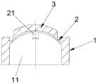
请参照图1和图2所示,为本发明实施例提供的一种出液控制阀100,其包括:本体部1、弧形隔膜2和加强肋3。Referring to FIG. 1 and FIG. 2 , a liquid
本体部1上开设有中心孔11;弧形隔膜2设置于本体部1上,并封堵中心孔11的一端开口;加强肋3设置于弧形隔膜2上,并位于弧形隔膜2的外凸面所在的一侧,弧形隔膜2和加强肋3均由具有形状记忆特性的材料制成,且加强肋3上具有贯穿加强肋和隔膜的切缝4。The
在上述实施例中,具体使用时,如图4所示,为出液控制阀100尚未使用状态下的结构示意图,参照图11所示,将该出液控制阀100卡入容器本体301内后,准备使用前,容器本体301处于自然倒立状态,参照图5所示,此时弧形隔膜2呈上拱状态,在内容物压力作用下,整个弧形隔膜2带动加强肋3整体受向下的压力,由于弧形隔膜2边缘较薄,首先向下拉直,上拱的加强肋3会相应地展平,由于加强肋3具有一定的抗压强度,加强肋3内部各处承受压应力,从而呈现拱桥效应,使得整体处于受力平衡状态,切缝被压紧,以防止内容物滴漏。参照图6所示,当容器本体301受到挤压时,中间部分的弧形隔膜2及加强肋3开始向下凹陷变形,继续参照图7和图8所示,随着用力加大,下凹部分扩展直至整个加强肋3呈下凹状态,此时整个加强肋内部受拉应力,内容物将切缝4撑开(即图3中出液控制阀所处的状态),从而可挤出内容物。由于挤出过程是渐进变化的,且加强肋3的设计使得切缝4的张开过程连续且柔和,参照图9所示,开口大小与挤压力度基本呈线性关系,因此不存在爆冲现象。同理,当给容器本体301松压时,与挤压过程刚好相反,容器本体301内的负压及弧形隔膜2和加强肋3自身的形状记忆恢复力,使阀门开口闭合,弧形隔膜2及加强肋3恢复到初始状态,在恢复过程中,能够将阀门外的残留内容物部分或全部吸回到容器本体301内,以保持口部的清洁。由此,利用该出液控制阀100能够提高包装容器的使用效果。需要说明的是,本实施例中,图9所示的压力与开口面积及出液量的关系曲线图只是为了方便说明而做的定性示意图,实际曲线会因产品使用场合、产品使用要求、产品结构参数的不同而不同。In the above embodiment, when in use, as shown in FIG. 4 , it is a schematic structural diagram of the liquid
在上述实施例中,对加强肋3的数量不做限定。优选的,加强肋3的数量为两个,两个加强肋3在本体部1的横截面上的投影相互垂直。由此,可形成十字形开口,当受到挤压力后,十字形开口能够均匀地张开,从而能够均匀地挤出容器本体内的内容物。当然,在其他实施例中,加强肋3的数量也可以是四个,从而使得四个加强肋3形成“米”字形形状。In the above embodiment, the number of the reinforcing
参照图2所示,在上述实施例中,优选的,弧形隔膜2的内凹面上与加强肋3相对应的位置处具有V型槽21,切缝4位于V型槽21的底部。具体的,在本实施例中,通过在弧形隔膜2的内凹面上与加强肋3相对应的位置挖出一定长度的两条V型槽21,从而能够利用锋利的刀片沿着两条V型槽21的根部分别切开相应长度的切缝4。利用该V型槽21能够在切割操作时对刀片起导向作用,从而便于精确切口的位置,同时,该V型槽21还具有调节出液状态、稳定出液流的作用,并能够更加容易地回吸内容物,从而减少内容物残留,保证口部洁净。Referring to FIG. 2 , in the above embodiment, preferably, the inner concave surface of the arc-shaped
在上述实施例中,优选的,本体部1上具有第一连接部(图中未示出),本体部1能够插入容器本体的开口部内,以使第一连接部能够与设置在容器本体上的第二连接部连接,从而固定本体部1与容器本体的相对位置;弧形隔膜2朝向容器本体的底部弯曲。具体的,在该实施例中,出液控制阀100可充当盖子使用,从而可将出液控制阀100直接安装到容器本体上,使得容器本体能够控制内容物的出液量。为提高容器本体的密封性,可将本体部1的外壁与容器本体的开口部的内壁过盈配合,或在本体部1的外壁与容器本体的开口部的内壁之间设置密封结构(例如:密封圈等)。In the above embodiment, preferably, the
在上述实施例中,对弧形隔膜2的弯曲方向不做具体限定;参照本申请图1和图2所示,弧形隔膜2沿远离中心孔11的另一端的方向弯曲设定的弧度。参照图10所示,弧形隔膜2还可以沿靠近中心孔11的另一端的方向弯曲设定的弧度,其工作原理与图1和图2中所示的出液控制阀的工作原理相同,只要安装使用时,保证弧形隔膜2的弯曲方向朝向容器本体的底部即可。In the above embodiment, the bending direction of the arc-shaped
在上述实施例中,优选的,本体部1、弧形隔膜2和加强肋3一体成型。由此不仅能够保证本体部1、弧形隔膜2和加强肋3之间的密封性,而且能够避免二次组装,从而有利于提高生产效率。In the above embodiment, preferably, the
实施例二:Embodiment 2:
参照图11所示,本发明实施例还提供了一种可控制出液量的盖子200,其包括上盖201、下盖202和本发明实施例一所述的出液控制阀100。Referring to FIG. 11 , an embodiment of the present invention further provides a
上盖201可翻转地安装在下盖202上,下盖202的中心具有通道部203;本体部1容置在通道部203内,且弧形隔膜2沿远离上盖201的方向弯曲,上盖201能够与下盖202相扣合,以封堵中心孔11另一端的开口。The
在本实施例中,具体使用时,参照图12所示,可将盖子200盖设到容器本体301上,并使得通道部203插设在容器本体301的开口部内。当需要取用容器本体301的内容物时,可挤压容器本体301,从而使得通道部203内的出液控制阀100依次经历从图4至图8所示的过程,进而能够将内容物连续且柔和地挤出,当取用完毕后,松开对容器本体301的挤压,则出液控制阀100在容器本体301内的负压及弧形隔膜2和加强肋3自身的形状记忆恢复力作用下恢复原状,并将开口部的内容物吸回到容器本体301内部,以保证开口部的洁净。由此,利用该盖子200能够对出液量进行控制,以提高用户的使用效果。In this embodiment, in specific use, as shown in FIG. 12 , the
在上述实施例中,优选的,还包括密封环(图中未示出),密封环套设在本体部1上,并位于本体部1的外壁与通道部203的内壁之间,以封堵本体部1的外壁与通道部203的内壁之间的缝隙。由此,利用该密封环能够提高出液控制阀100与下盖202之间的密封性,从而能够避免内容物从本体部1的外壁与通道部203的内壁之间的缝隙流出。In the above embodiment, it is preferable to further include a sealing ring (not shown in the figure), the sealing ring is sleeved on the
能够理解的是,通过设置密封环提高密封性仅为其中一种较好的实施方式,还可以通过其他方式来实现密封的效果,例如:将本体部1的外壁与通道部203的内壁过盈配合,或在本体部1的外壁与通道部203的内壁之间填充胶状物等。It can be understood that improving the sealing performance by providing a sealing ring is only one of the better embodiments, and other methods can also be used to achieve the sealing effect, for example: interfering the outer wall of the
实施例三:Embodiment three:
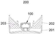
参照图12所示,本发明实施例还提供一种包装容器300,其包括容器本体301以及实施例二中所述的盖子200,下盖202盖设在容器本体301上,且通道部203相应地插设在容器本体301的开口部内。Referring to FIG. 12, an embodiment of the present invention further provides a
在本实施例中,具体组装时,首先将出液控制阀100卡入盖子200的通道部203内,以固定出液控制阀100与下盖202的相对位置,防止出液控制阀100在使用过程中出现位移或脱落的情况,然后,将下盖202螺纹连接在容器本体301的开口部上,并使得通道部203插入容器本体301的开口部内,以完成组装过程。具体使用时,当需要取用容器本体301的内容物时,可挤压容器本体301,从而使得通道部203内的出液控制阀100依次经历从图4至图8所示的过程,进而能够将内容物连续且柔和地挤出,当取用完毕后,松开对容器本体301的挤压,则出液控制阀100在容器本体301内的负压及弧形隔膜2和加强肋3自身的形状记忆恢复力作用下恢复原状,并将开口部的内容物吸回到容器本体301内部,以保证开口部的洁净。由此,利用该包装容器300能够提高用户的使用体验,从而提高包装容器300使用的便利性。In this embodiment, during the specific assembly, the liquid
在上述实施例中,优选的,通道部203的外壁上形成有环形凸起部(图中未示出),环形凸起部能够与开口部的内壁过盈配合,以封堵通道部203的外壁与开口部的内壁之间的缝隙。由此,利用该环形凸起部能够提高下盖202与容器本体301之间的密封性,避免内容物从下盖202与容器本体301之间的缝隙流出。In the above embodiment, preferably, an annular raised portion (not shown in the figure) is formed on the outer wall of the
同时,能够理解的是,通过在通道部203的外壁上设置环形凸起部以提高密封性仅为其中一种较好的实施方式,还可以通过其他方式来实现密封的效果,例如:在通道部203的外壁与开口部的内壁之间设置密封环,或在通道部203的外壁与开口部的内壁之间填充胶状物等。At the same time, it can be understood that it is only one of the better embodiments to provide an annular raised portion on the outer wall of the
在本说明书的描述中,参考术语“一个实施例”、“一些实施例”、“示例”、“具体示例”、或“一些示例”等的描述意指结合该实施例或示例描述的具体特征、结构、材料或者特点包含于本发明的至少一个实施例或示例中。而且,描述的具体特征、结构、材料或者特点可以在任一个或多个实施例或示例中以合适的方式结合。此外,在不相互矛盾的情况下,本领域的技术人员可以将本说明书中描述的不同实施例或示例以及不同实施例或示例的特征进行结合和组合。In the description of this specification, description with reference to the terms "one embodiment," "some embodiments," "example," "specific example," or "some examples", etc., mean specific features described in connection with the embodiment or example , structure, material or feature is included in at least one embodiment or example of the present invention. Furthermore, the particular features, structures, materials or characteristics described may be combined in any suitable manner in any one or more embodiments or examples. Furthermore, those skilled in the art may combine and combine the different embodiments or examples described in this specification, as well as the features of the different embodiments or examples, without conflicting each other.
此外,术语“第一”、“第二”仅用于描述目的,而不能理解为指示或暗示相对重要性或者隐含指明所指示的技术特征的数量。由此,限定有“第一”、“第二”的特征可以明示或隐含地包括至少一个该特征。在本发明的描述中,“多个”的含义是两个或两个以上,除非另有明确具体的限定。In addition, the terms "first" and "second" are only used for descriptive purposes, and should not be construed as indicating or implying relative importance or implying the number of indicated technical features. Thus, a feature delimited with "first", "second" may expressly or implicitly include at least one of that feature. In the description of the present invention, "plurality" means two or more, unless otherwise expressly and specifically defined.
以上所述,仅为本发明的具体实施方式,但本发明的保护范围并不局限于此,任何熟悉本技术领域的技术人员在本发明揭露的技术范围内,可轻易想到变化或替换,都应涵盖在本发明的保护范围之内。因此,本发明的保护范围应以所述权利要求的保护范围为准。The above are only specific embodiments of the present invention, but the protection scope of the present invention is not limited to this. Any person skilled in the art can easily think of changes or substitutions within the technical scope disclosed by the present invention. should be included within the protection scope of the present invention. Therefore, the protection scope of the present invention should be based on the protection scope of the claims.
Claims (10)
Priority Applications (1)
| Application Number | Priority Date | Filing Date | Title |
|---|---|---|---|
| CN202010889463.3ACN111924314A (en) | 2020-08-28 | 2020-08-28 | A liquid outlet control valve, a lid capable of controlling the amount of liquid outlet, and a packaging container |
Applications Claiming Priority (1)
| Application Number | Priority Date | Filing Date | Title |
|---|---|---|---|
| CN202010889463.3ACN111924314A (en) | 2020-08-28 | 2020-08-28 | A liquid outlet control valve, a lid capable of controlling the amount of liquid outlet, and a packaging container |
Publications (1)
| Publication Number | Publication Date |
|---|---|
| CN111924314Atrue CN111924314A (en) | 2020-11-13 |
Family
ID=73309491
Family Applications (1)
| Application Number | Title | Priority Date | Filing Date |
|---|---|---|---|
| CN202010889463.3AWithdrawnCN111924314A (en) | 2020-08-28 | 2020-08-28 | A liquid outlet control valve, a lid capable of controlling the amount of liquid outlet, and a packaging container |
Country Status (1)
| Country | Link |
|---|---|
| CN (1) | CN111924314A (en) |
Citations (6)
| Publication number | Priority date | Publication date | Assignee | Title |
|---|---|---|---|---|
| US5213236A (en)* | 1991-12-06 | 1993-05-25 | Liquid Molding Systems, Inc. | Dispensing valve for packaging |
| JPH10139080A (en)* | 1996-11-08 | 1998-05-26 | Yoshino Kogyosho Co Ltd | Slit valve of container for discharging content |
| CN105228574A (en)* | 2012-12-18 | 2016-01-06 | 特洛伊海伦有限公司 | For the suction nozzle of lid |
| JP2016050007A (en)* | 2014-08-29 | 2016-04-11 | 株式会社吉野工業所 | Cap with slit valve |
| CN109124737A (en)* | 2018-08-17 | 2019-01-04 | 联合微创医疗器械(深圳)有限公司 | A kind of sealing structure and puncture outfit |
| CN212314361U (en)* | 2020-08-28 | 2021-01-08 | 深圳市通产丽星科技集团有限公司 | Liquid outlet control valve, cover capable of controlling liquid outlet amount and packaging container |
- 2020
- 2020-08-28CNCN202010889463.3Apatent/CN111924314A/ennot_activeWithdrawn
Patent Citations (6)
| Publication number | Priority date | Publication date | Assignee | Title |
|---|---|---|---|---|
| US5213236A (en)* | 1991-12-06 | 1993-05-25 | Liquid Molding Systems, Inc. | Dispensing valve for packaging |
| JPH10139080A (en)* | 1996-11-08 | 1998-05-26 | Yoshino Kogyosho Co Ltd | Slit valve of container for discharging content |
| CN105228574A (en)* | 2012-12-18 | 2016-01-06 | 特洛伊海伦有限公司 | For the suction nozzle of lid |
| JP2016050007A (en)* | 2014-08-29 | 2016-04-11 | 株式会社吉野工業所 | Cap with slit valve |
| CN109124737A (en)* | 2018-08-17 | 2019-01-04 | 联合微创医疗器械(深圳)有限公司 | A kind of sealing structure and puncture outfit |
| CN212314361U (en)* | 2020-08-28 | 2021-01-08 | 深圳市通产丽星科技集团有限公司 | Liquid outlet control valve, cover capable of controlling liquid outlet amount and packaging container |
Similar Documents
| Publication | Publication Date | Title |
|---|---|---|
| US4991745A (en) | Dispensing valve with trampoline-like construction | |
| US4728006A (en) | Flexible container including self-sealing dispensing valve to provide automatic shut-off and leak resistant inverted storage | |
| US3635376A (en) | Quick-open flexible package | |
| US4178643A (en) | Valve for inflatable prosthesis | |
| MXPA02009623A (en) | Container with formed memory valve. | |
| NO331479B1 (en) | Flexible liquid container | |
| KR900014222A (en) | Flexible bags for liquid storage | |
| CN1302272A (en) | Slotted closing valve for opening of containers | |
| CN1040860C (en) | A bag or pouch for containing a fluid | |
| CN212314361U (en) | Liquid outlet control valve, cover capable of controlling liquid outlet amount and packaging container | |
| CN111924314A (en) | A liquid outlet control valve, a lid capable of controlling the amount of liquid outlet, and a packaging container | |
| CN101613005B (en) | Bottle structure | |
| US2540842A (en) | Self-sealing closure member | |
| EP0006709B1 (en) | Closure for a dispenser container | |
| US8282613B2 (en) | Disposable urine bag for collecting urine | |
| EP0334839A4 (en) | Self-sealable liquid dispensing container. | |
| US1951544A (en) | Self-sealing tube | |
| EP2832658A1 (en) | Dispensing container and method of filling the container | |
| JP6442793B1 (en) | Tube container and its mouth and neck | |
| CN201095462Y (en) | Sealed crimp hose with inner liner | |
| CN222743235U (en) | Bottle cap with self-sealing structure and safety structure | |
| CN216186819U (en) | Double-layer bottle with high production yield | |
| CN210407449U (en) | Box body | |
| CN208616459U (en) | The two-tube toothpaste packing of vapour-pressure type multitube lotion packaging and application lotion packaging | |
| CN203832912U (en) | Pasty fluid or liquid state material packaging bag |
Legal Events
| Date | Code | Title | Description |
|---|---|---|---|
| PB01 | Publication | ||
| PB01 | Publication | ||
| SE01 | Entry into force of request for substantive examination | ||
| SE01 | Entry into force of request for substantive examination | ||
| WW01 | Invention patent application withdrawn after publication | Application publication date:20201113 | |
| WW01 | Invention patent application withdrawn after publication |