CN111920452A - End execution device and method for neck ultrasonic scanning robot - Google Patents
End execution device and method for neck ultrasonic scanning robotDownload PDFInfo
- Publication number
- CN111920452A CN111920452ACN202010805664.0ACN202010805664ACN111920452ACN 111920452 ACN111920452 ACN 111920452ACN 202010805664 ACN202010805664 ACN 202010805664ACN 111920452 ACN111920452 ACN 111920452A
- Authority
- CN
- China
- Prior art keywords
- ultrasonic
- probe
- neck
- plate
- module
- Prior art date
- Legal status (The legal status is an assumption and is not a legal conclusion. Google has not performed a legal analysis and makes no representation as to the accuracy of the status listed.)
- Pending
Links
- 238000000034methodMethods0.000titleclaimsabstractdescription19
- 239000000523sampleSubstances0.000claimsabstractdescription206
- 239000012636effectorSubstances0.000claimsabstractdescription24
- 238000002604ultrasonographyMethods0.000claimsdescription41
- 238000001514detection methodMethods0.000claimsdescription13
- 238000009434installationMethods0.000description15
- 230000001133accelerationEffects0.000description6
- 238000003745diagnosisMethods0.000description5
- 230000009286beneficial effectEffects0.000description4
- 210000001715carotid arteryAnatomy0.000description4
- 208000009453Thyroid NoduleDiseases0.000description2
- 230000006870functionEffects0.000description2
- 230000001575pathological effectEffects0.000description2
- 230000008569processEffects0.000description2
- 210000001685thyroid glandAnatomy0.000description2
- 206010028980NeoplasmDiseases0.000description1
- 239000008280bloodSubstances0.000description1
- 210000004369bloodAnatomy0.000description1
- 210000004204blood vesselAnatomy0.000description1
- 210000004556brainAnatomy0.000description1
- 201000011510cancerDiseases0.000description1
- 230000008859changeEffects0.000description1
- 201000010099diseaseDiseases0.000description1
- 208000037265diseases, disorders, signs and symptomsDiseases0.000description1
- 230000003862health statusEffects0.000description1
- 230000004048modificationEffects0.000description1
- 238000012986modificationMethods0.000description1
- 230000008447perceptionEffects0.000description1
Images


Classifications
- A—HUMAN NECESSITIES
- A61—MEDICAL OR VETERINARY SCIENCE; HYGIENE
- A61B—DIAGNOSIS; SURGERY; IDENTIFICATION
- A61B8/00—Diagnosis using ultrasonic, sonic or infrasonic waves
- A61B8/08—Clinical applications
- A61B8/0833—Clinical applications involving detecting or locating foreign bodies or organic structures
- A61B8/085—Clinical applications involving detecting or locating foreign bodies or organic structures for locating body or organic structures, e.g. tumours, calculi, blood vessels, nodules
- A—HUMAN NECESSITIES
- A61—MEDICAL OR VETERINARY SCIENCE; HYGIENE
- A61B—DIAGNOSIS; SURGERY; IDENTIFICATION
- A61B8/00—Diagnosis using ultrasonic, sonic or infrasonic waves
- A61B8/42—Details of probe positioning or probe attachment to the patient
- A61B8/4245—Details of probe positioning or probe attachment to the patient involving determining the position of the probe, e.g. with respect to an external reference frame or to the patient
- A61B8/4254—Details of probe positioning or probe attachment to the patient involving determining the position of the probe, e.g. with respect to an external reference frame or to the patient using sensors mounted on the probe
- A—HUMAN NECESSITIES
- A61—MEDICAL OR VETERINARY SCIENCE; HYGIENE
- A61B—DIAGNOSIS; SURGERY; IDENTIFICATION
- A61B8/00—Diagnosis using ultrasonic, sonic or infrasonic waves
- A61B8/44—Constructional features of the ultrasonic, sonic or infrasonic diagnostic device
- A61B8/4444—Constructional features of the ultrasonic, sonic or infrasonic diagnostic device related to the probe
- A61B8/4461—Features of the scanning mechanism, e.g. for moving the transducer within the housing of the probe
- A—HUMAN NECESSITIES
- A61—MEDICAL OR VETERINARY SCIENCE; HYGIENE
- A61B—DIAGNOSIS; SURGERY; IDENTIFICATION
- A61B8/00—Diagnosis using ultrasonic, sonic or infrasonic waves
- A61B8/54—Control of the diagnostic device
- G—PHYSICS
- G01—MEASURING; TESTING
- G01L—MEASURING FORCE, STRESS, TORQUE, WORK, MECHANICAL POWER, MECHANICAL EFFICIENCY, OR FLUID PRESSURE
- G01L5/00—Apparatus for, or methods of, measuring force, work, mechanical power, or torque, specially adapted for specific purposes
- G01L5/16—Apparatus for, or methods of, measuring force, work, mechanical power, or torque, specially adapted for specific purposes for measuring several components of force
Landscapes
- Health & Medical Sciences (AREA)
- Life Sciences & Earth Sciences (AREA)
- Physics & Mathematics (AREA)
- Medical Informatics (AREA)
- Surgery (AREA)
- Pathology (AREA)
- Radiology & Medical Imaging (AREA)
- Engineering & Computer Science (AREA)
- Biomedical Technology (AREA)
- Heart & Thoracic Surgery (AREA)
- Biophysics (AREA)
- Molecular Biology (AREA)
- Nuclear Medicine, Radiotherapy & Molecular Imaging (AREA)
- Animal Behavior & Ethology (AREA)
- General Health & Medical Sciences (AREA)
- Public Health (AREA)
- Veterinary Medicine (AREA)
- General Physics & Mathematics (AREA)
- Vascular Medicine (AREA)
- Ultra Sonic Daignosis Equipment (AREA)
Abstract
Translated fromChinese
Description
Translated fromChinese技术领域technical field
本发明涉及颈部扫描技术领域,特别涉及一种颈部超声扫描机器人末端执行装置及方法。The invention relates to the technical field of neck scanning, in particular to an end effector and a method of a neck ultrasonic scanning robot.
背景技术Background technique
甲状腺结节是指在甲状腺内的肿块,长到一定程度时,可能引发为癌症。因此,需要对颈部甲状腺结节进行扫查,防止病情的进一步扩展。“颈动脉”负责向大脑供血的血管生命线,其健康状态的超声检查也尤为重要。Thyroid nodules are lumps in the thyroid gland that, when grown enough, can lead to cancer. Therefore, it is necessary to scan the neck thyroid nodules to prevent further expansion of the disease. The "carotid artery" is responsible for the lifeline of blood vessels supplying blood to the brain, and ultrasound examination of its health status is also particularly important.
经检索,公开号为CN110755110A的中国发明专利,涉及一种基于机械臂单元的三维超声扫查装置。该扫查装置包括机械臂单元,机械臂单元的一端安装在移动底座上,另一端通过连接连接块,连接块通过压力传感器与超声探头连接,空间信息感知单元安装在移动底座上,利用机械臂单元、空间信息感知单元、压力传感器、显示器等解决了己有的三维超声设备只能获取较小范围三维超声图像的问题,保证了高质量的三维超声图像重建结果。但该发明的末端执行装置中只有一个扫描探头,适用于身体曲线变化平缓的部位,在扫描颈部时不能够自适应调整。After retrieval, the Chinese invention patent with the publication number CN110755110A relates to a three-dimensional ultrasonic scanning device based on a robotic arm unit. The scanning device includes a robotic arm unit. One end of the robotic arm unit is installed on the mobile base, and the other end is connected with a connecting block. The connecting block is connected with the ultrasonic probe through a pressure sensor. The spatial information sensing unit is installed on the moving base. The unit, spatial information perception unit, pressure sensor, display, etc. solve the problem that existing 3D ultrasound equipment can only obtain 3D ultrasound images in a small range, and ensure high-quality 3D ultrasound image reconstruction results. However, there is only one scanning probe in the end effector of the invention, which is suitable for the part where the curve of the body changes gently, and cannot be adjusted adaptively when scanning the neck.
现有技术中,公开号为CN110575203A的中国发明专利,提供了一种甲状腺超声检测设备及其检测方法,其检测设备包括超声主机,超声主机与检测床相邻放置,支撑移动装置固定安装在超声主机上,扫查装置设置于支撑移动装置的端部并悬于检测床上,该发明减低了专业人力资源成本,扫查更为方便快捷。但该发明的扫查装置用的是压力弹簧与病人待检测部位贴合,并通过一套激光设备实现路径指引功能,结构较复杂,存在一定的舒适度问题。另外,该扫查装置为自研的一种装置,不能够使用现有的标准探头,成本较高。而且该扫查装置只具有一个探头,扫查范围小,准确度也较低。In the prior art, the Chinese invention patent with the publication number CN110575203A provides a thyroid ultrasound detection device and a detection method thereof. On the host, the scanning device is arranged at the end of the supporting mobile device and suspended on the detection bed. The invention reduces the cost of professional human resources and makes the scanning more convenient and quicker. However, the scanning device of the invention uses a pressure spring to fit the patient's part to be detected, and realizes the path guidance function through a set of laser equipment. The structure is complicated, and there is a certain comfort problem. In addition, the scanning device is a self-developed device, cannot use the existing standard probe, and has high cost. Moreover, the scanning device has only one probe, the scanning range is small, and the accuracy is also low.
公开号为CN110974307A的中国发明专利,提供了一种旋转锁定装置及超声装置,旋转锁定装置适用于颈动脉扫查超声装置,所述颈动脉扫查超声装置包括头套和探头扫查装置,所述旋转锁定装置包括可相互锁定的第一锁定部与第二锁定部。在通电状态下,所述第一锁定部与所述第二锁定部相互锁定使得所述探头扫查装置锁定于所述侧壁上;在断电状态下,所述探头扫查装置相对所述侧壁的转动。该装置能够克服现有的颈动脉扫查装置中的旋转锁定装置操作不便和医生容易漏操作的问题。但该装置结构复杂,没有力反馈,不能够自适应的调节锁定装置的角度,患者不能得到良好的诊断体验。The Chinese invention patent publication number CN110974307A provides a rotation locking device and an ultrasonic device. The rotation locking device is suitable for a carotid artery scanning ultrasonic device. The carotid artery scanning ultrasonic device includes a headgear and a probe scanning device. The rotation locking device includes a first locking portion and a second locking portion that can be locked with each other. In the power-on state, the first locking part and the second locking part are mutually locked so that the probe scanning device is locked on the side wall; in the power-off state, the probe scanning device is relatively opposite to the Rotation of the side walls. The device can overcome the problems that the rotation locking device in the existing carotid artery scanning device is inconvenient to operate and the doctor easily misses the operation. However, the device has a complex structure, has no force feedback, and cannot adjust the angle of the locking device adaptively, and patients cannot obtain a good diagnosis experience.
发明内容SUMMARY OF THE INVENTION
本发明针对上述现有技术中存在的问题,提出一种颈部超声扫描机器人末端执行装置及方法,具有力位控制保护功能,避免了探头与病人接触力过大导致的病人安全问题,且该机械结构简单可靠,维护方便,灵活精确。Aiming at the problems existing in the above-mentioned prior art, the present invention proposes a neck ultrasonic scanning robot end effector and method, which has the function of force-position control and protection, and avoids the problem of patient safety caused by excessive contact force between the probe and the patient. The mechanical structure is simple and reliable, easy to maintain, flexible and precise.
为解决上述技术问题,本发明是通过如下技术方案实现的:In order to solve the above-mentioned technical problems, the present invention is achieved through the following technical solutions:
本发明提供一种颈部超声扫描机器人末端执行装置,其包括:颈部夹持模块、左探头模块、右探头模块以及力位控制模块;其中,The present invention provides an end effector of a neck ultrasonic scanning robot, which comprises: a neck clamping module, a left probe module, a right probe module and a force position control module; wherein,
所述颈部夹持模块进一步包括:左板、右板以及旋转轴;其中,The neck clamping module further includes: a left plate, a right plate and a rotating shaft; wherein,
所述左板与所述右板通过所述旋转轴相连,所述旋转轴用于当所述左板以及所述右板之间的角度调整好之后对其进行固定;The left plate and the right plate are connected through the rotating shaft, and the rotating shaft is used to fix the angle between the left plate and the right plate after the angle is adjusted;
所述左探头模块设置在所述左板上;所述左探头模块用于对颈部进行扫描;the left probe module is arranged on the left plate; the left probe module is used for scanning the neck;
所述右探头模块设置在所述右板上;所述右超声探头模块用于对颈部进行扫描;the right probe module is arranged on the right plate; the right ultrasonic probe module is used for scanning the neck;
所述力位控制模块用于采集所述左探头模块和/或所述右探头模块与颈部皮肤的接触情况和/或接触力,以根据所述左探头模块和/或所述右探头模块与颈部皮肤的接触情况和/或接触力来控制所述左探头模块和/或所述右探头模块的姿态角度和/或位置。The force and position control module is used to collect the contact situation and/or the contact force between the left probe module and/or the right probe module and the neck skin, so as to adjust the contact force according to the left probe module and/or the right probe module. The attitude angle and/or position of the left probe module and/or the right probe module are controlled by the contact situation and/or the contact force with the neck skin.
较佳地,所述力位控制模块进一步包括:接触采集单元、安装单元以及固定单元;Preferably, the force and position control module further comprises: a contact collecting unit, an installation unit and a fixing unit;
所述接触采集单元进一步包括:摄像头和/或力传感器;其中,The contact acquisition unit further includes: a camera and/or a force sensor; wherein,
所述摄像头用于观察所述左探头模块以及所述右探头模块与颈部的接触情况,以便根据所述接触情况对所述左探头模块以及所述右探头模块的超声探头的姿态角度进行调节,以便于使所述超声探头与所述颈部更好地接触;The camera is used to observe the contact situation between the left probe module and the right probe module and the neck, so as to adjust the posture angle of the ultrasonic probes of the left probe module and the right probe module according to the contact situation , so as to make the ultrasonic probe better contact with the neck;
所述力传感器分别与所述左板以及所述安装单元相连,或分别与所述右板以及所述安装单元相连,用于采集所述左、右探头模块以及所述左、右探头模块的超声探头与颈部皮肤的接触力,以便根据所述接触力对所述超声探头的位置进行控制,以便于对所述颈部进行安全保护;The force sensor is respectively connected with the left plate and the installation unit, or is connected with the right plate and the installation unit respectively, and is used for collecting the left and right probe modules and the left and right probe modules. The contact force between the ultrasonic probe and the skin of the neck, so that the position of the ultrasonic probe can be controlled according to the contact force, so as to facilitate the safety protection of the neck;
所述安装单元用于与机器人手臂相连;the installation unit is used for connecting with the robot arm;
所述固定单元设置于所述安装单元上,用于对所述安装单元与所述机器人手臂进行固定。The fixing unit is arranged on the installation unit and is used for fixing the installation unit and the robot arm.
较佳地,所述力传感器的检测精度大于等于100g。Preferably, the detection accuracy of the force sensor is greater than or equal to 100g.
较佳地,所述力传感器的最大检测值为91kg。Preferably, the maximum detection value of the force sensor is 91kg.
较佳地,所述左探头模块进一步包括:左超声探头、左超声调节板以及左超声调节轴;其中,Preferably, the left probe module further comprises: a left ultrasonic probe, a left ultrasonic adjustment plate and a left ultrasonic adjustment shaft; wherein,
所述左超声探头与所述左超声调节板相连;the left ultrasonic probe is connected with the left ultrasonic adjustment plate;
所述左超声调节板设置于所述左板上;the left ultrasonic adjustment plate is arranged on the left plate;
所述左超声调节板与所述左超声调节轴相连;the left ultrasonic adjustment plate is connected with the left ultrasonic adjustment shaft;
所述左超声调节轴用于根据所述力位控制模块采集到的接触情况对所述左超声调节板的姿态角度调节,进而对所述左超声探头的姿态角度进行调节。The left ultrasonic adjustment axis is used to adjust the attitude angle of the left ultrasonic adjustment plate according to the contact situation collected by the force position control module, and then adjust the attitude angle of the left ultrasonic probe.
较佳地,所述左超声调节板设置于所述左板的远离所述颈部的一侧;Preferably, the left ultrasonic adjustment plate is arranged on the side of the left plate away from the neck;
所述左超声探头穿过所述左超声调节板以及所述左板,用于使所述左超声探头与所述颈部接触。The left ultrasonic probe passes through the left ultrasonic adjustment plate and the left plate, and is used for contacting the left ultrasonic probe with the neck.
较佳地,所述右探头模块进一步包括:右超声探头、右超声调节板以及右超声调节轴;其中,Preferably, the right probe module further comprises: a right ultrasonic probe, a right ultrasonic adjustment plate and a right ultrasonic adjustment shaft; wherein,
所述右超声探头设置于所述右超声调节板上;the right ultrasonic probe is arranged on the right ultrasonic adjustment plate;
所述右超声调节板与所述右超声调节轴相连;the right ultrasonic adjustment plate is connected with the right ultrasonic adjustment shaft;
所述右超声调节轴用于根据所述力位控制模块采集到的接触情况对所述右超声调节板的姿态角度调节,进而对所述右超声探头的姿态角度进行调节。The right ultrasonic adjustment axis is used to adjust the attitude angle of the right ultrasonic adjustment plate according to the contact situation collected by the force position control module, and then adjust the attitude angle of the right ultrasonic probe.
较佳地,所述右超声调节板设置于所述右板的远离所述颈部的一侧;Preferably, the right ultrasonic adjustment plate is arranged on the side of the right plate away from the neck;
所述右超声探头穿过所述右超声调节板以及所述右板,用于使所述右超声探头与所述颈部接触。The right ultrasonic probe passes through the right ultrasonic adjustment plate and the right plate, and is used for contacting the right ultrasonic probe with the neck.
本发明还提供一种颈部超声扫描机器人末端执行方法,其用于上述所述的颈部超声扫描机器人末端装置的执行方法,包括以下步骤:The present invention also provides a method for executing the end of a neck ultrasonic scanning robot, which is used for the above-mentioned execution method of the end device of a neck ultrasonic scanning robot, including the following steps:
S101:调节所述左板与所述右板之间的角度,以适应颈部的弧度,调整好角度后,将所述旋转轴锁紧;S101: Adjust the angle between the left plate and the right plate to adapt to the curvature of the neck, and after adjusting the angle, lock the rotating shaft;
S102:通过所述力位控制模块观察所述左探头模块和/或所述右探头模块的超声模块与所述颈部的接触情况,以根据所述左探头模块和/或所述右探头模块的超声探头与所述颈部的接触情况来控制所述超声探头的姿态角度,以便于使所述超声探头与所述颈部更好地接触;S102: Observing the contact situation between the ultrasonic module of the left probe module and/or the right probe module and the neck through the force position control module, so as to determine the contact condition of the left probe module and/or the right probe module according to the The contact situation of the ultrasonic probe and the neck is controlled to control the attitude angle of the ultrasonic probe, so as to make the ultrasonic probe better contact with the neck;
S103:通过所述力位控制模块采集所述左探头模块和/或所述右探头模块的超声模块与所述颈部的接触力,以根据所述左探头模块和/或所述右探头模块的超声探头与所述颈部的接触力来控制所述超声探头的位置,以便于对所述颈部进行安全保护。S103: Collect the contact force between the ultrasonic module of the left probe module and/or the right probe module and the neck through the force position control module, so as to measure the contact force of the left probe module and/or the right probe module according to the The contact force between the ultrasonic probe and the neck is used to control the position of the ultrasonic probe, so as to protect the neck safely.
相较于现有技术,本发明实施例至少具有以下一种优点:Compared with the prior art, the embodiment of the present invention has at least one of the following advantages:
(1)本发明提供的颈部超声扫描机器人末端执行装置及方法,通过力位控制模块对左、右超声探头与颈部的接触位置进行观察已对其姿态角度进行控制,将其由过去的不可控状态变为了可控状态,可以使超声探头与颈部更好地接触,进而协助医生对超声探头在颈部表面进行准确定位;(1) In the end effector and method of the neck ultrasonic scanning robot provided by the present invention, the contact position of the left and right ultrasonic probes and the neck has been observed through the force position control module, and the attitude angle has been controlled. The uncontrollable state has become a controllable state, which can make the ultrasound probe better contact with the neck, thereby assisting the doctor to accurately position the ultrasound probe on the neck surface;
(2)本发明提供的颈部超声扫描机器人末端执行装置及方法,通过力位控制模块对左、右超声探头与颈部的接触力进行检测已对其位置进行控制,将其由过去的不可控状态变为了可控状态,从而实现了对病人的安全保护,极大地提高了治疗过程的人性化和舒适度;(2) In the end effector and method of the neck ultrasonic scanning robot provided by the present invention, the contact force between the left and right ultrasonic probes and the neck is detected by the force position control module, and the position thereof has been controlled, and its position has been controlled by the force and position control module. The control state has become a controllable state, thereby realizing the safety protection of the patient and greatly improving the humanization and comfort of the treatment process;
(3)本发明提供的颈部超声扫描机器人末端执行装置及方法,通过左、右超声探头模块的扫描方式,可以采集更丰富的颈部组织信息,有利于病人颈部病理信息的有效诊断;此外,由于左、右超声探头模块之间的几何信息、机器人的位姿信息已知,因此非常有利于后续进行颈部组织的三维重构与精准诊断;(3) The neck ultrasonic scanning robot end effector and method provided by the present invention can collect more abundant neck tissue information through the scanning method of the left and right ultrasonic probe modules, which is beneficial to the effective diagnosis of the patient's neck pathological information; In addition, since the geometric information between the left and right ultrasound probe modules and the pose information of the robot are known, it is very beneficial to the subsequent three-dimensional reconstruction and accurate diagnosis of neck tissue;
(4)本发明提供的颈部超声扫描机器人末端执行装置及方法,通过对力传感器的检测精度进行设置,可以避免当加速运动产生加速力时,产生误判;(4) In the end effector and method of the neck ultrasonic scanning robot provided by the present invention, by setting the detection accuracy of the force sensor, misjudgment can be avoided when the acceleration force is generated by the acceleration movement;
(5)本发明提供的颈部超声扫描机器人末端执行装置及方法,通过对力传感器设置最大检测值,如果超过这个上限,力传感器将会产生损坏,由于与病人的接触力有限,力传感器可一直处于安全的工作状态,保护力度更大。(5) The end effector and method of the neck ultrasonic scanning robot provided by the present invention set the maximum detection value for the force sensor. If the upper limit is exceeded, the force sensor will be damaged. Due to the limited contact force with the patient, the force sensor can be damaged. Always in a safe working state with greater protection.
附图说明Description of drawings
下面结合附图对本发明的实施方式作进一步说明:Embodiments of the present invention are further described below in conjunction with the accompanying drawings:
图1为本发明一实施例的颈部超声扫描机器人末端执行装置的三维视图;1 is a three-dimensional view of a neck ultrasound scanning robot end effector according to an embodiment of the present invention;
图2为本发明一实施例的颈部超声扫描机器人末端执行装置的平视图;2 is a plan view of an end effector for a neck ultrasound scanning robot according to an embodiment of the present invention;
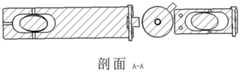
图3为图2的A-A方向的剖视图。FIG. 3 is a cross-sectional view taken along the line A-A in FIG. 2 .
标号说明:1-左板,2-右板,3-旋转轴,4-安装单元,5-摄像头,6-固定单元,7-左超声探头,8-右超声探头,9-左超声调节板,10-右超声调节板,11-左超声调节轴,12-右超声调节轴,13-力传感器,14-颈部。Label description: 1-left plate, 2-right plate, 3-rotating shaft, 4-installation unit, 5-camera, 6-fixed unit, 7-left ultrasonic probe, 8-right ultrasonic probe, 9-left ultrasonic adjustment plate , 10-right ultrasonic adjustment plate, 11-left ultrasonic adjustment shaft, 12-right ultrasonic adjustment shaft, 13-force transducer, 14-neck.
具体实施方式Detailed ways
下面对本发明的实施例作详细说明,本实施例在以本发明技术方案为前提下进行实施,给出了详细的实施方式和具体的操作过程,但本发明的保护范围不限于下述的实施例。The embodiments of the present invention are described in detail below. This embodiment is implemented on the premise of the technical solution of the present invention, and provides a detailed implementation manner and a specific operation process, but the protection scope of the present invention is not limited to the following implementation. example.
如图1所示为本发明一实施例的颈部超声扫描机器人末端执行装置的三维视图,如图2所示为本发明一实施例的颈部超声扫描机器人末端执行装置的平视图;图3为图2的A-A方向的剖视图。FIG. 1 is a three-dimensional view of an end effector for a neck ultrasound scanning robot according to an embodiment of the present invention, and FIG. 2 is a plan view of an end effector for a neck ultrasound scanning robot according to an embodiment of the present invention; FIG. 3 It is a sectional view taken along the line A-A in FIG. 2 .
请参考图1-图3,本实施例的颈部超声扫描机器人末端执行装置包括:颈部夹持模块、左探头模块、右探头模块以及力位控制模块。其中,颈部夹持模块进一步包括:左板1、右板2以及旋转轴3;其中,左板1与右板2通过旋转轴3相连,左板1与右板2之间的角度可以调节,以适应颈部(脖子)14的弧度,旋转轴3用于当左板1以及右板2之间的角度调整好之后对其进行固定。左探头模块设置在左板1上;左探头模块用于对颈部进行扫描。右探头模块设置在右板2上;右超声探头模块用于对颈部进行扫描。力位控制模块用于采集左探头模块和/或右探头模块与颈部皮肤的接触情况和/或接触力,以根据左探头模块和/或右探头模块与颈部皮肤的接触情况和/或接触力来控制左探头模块和/或右探头模块的姿态角度和/或位置。Referring to FIGS. 1-3 , the end effector of the neck ultrasound scanning robot in this embodiment includes: a neck clamping module, a left probe module, a right probe module, and a force position control module. The neck clamping module further includes: a left plate 1, a
本实施例中,力位控制模块进一步包括:接触采集单元、安装单元4以及固定单元6;接触采集单元进一步包括:摄像头5和/或力传感器13。其中,摄像头5用于观察左探头模块以及所述右探头模块与颈部的接触情况,以便根据接触情况对所述左探头模块以及右探头模块的超声探头的姿态角度进行调节,以便于使超声探头与颈部更好地接触,进而协助医生对超声探头在颈部表面进行准确定位。本实施例中,摄像头5设置于右板上,不同实施例中,也可设置在其他合适的位置。力传感器13分别与右板2以及安装单元14相连,用于采集左探头模块以及右探头模块的超声探头与颈部皮肤的接触力,以便根据接触力对超声探头的位置进行控制,以便于对颈部进行安全保护。当接触力小于预设接触力时,可控制超声探头下移,更靠近颈部14,当接触力大于预设接触力时,可控制超声探头上升,更远离颈部14,从而实现对病人的安全保护控制。安装单元4用于与机器人手臂相连,一实施例中,可以采用安装法兰。固定单元6设置于安装单元4上,用于对安装单元4与机器人手臂进行固定,一实施例中,可以采用固定螺栓。In this embodiment, the force position control module further includes: a contact collection unit, an
不同实施例中,力传感器13也可分别与左板1以及安装单元14相连,具体实现原理与上述实施例相同。In different embodiments, the
本实施例中,左探头模块进一步包括:左超声探头7、左超声调节板9以及左超声调节轴11。其中,左超声调节板9设置于左板1,且左超声调节板9设置于左板的远离颈部的一侧。左超声探头7穿过左超声调节板9以及左板1,用于使左超声探头7与颈部14接触。左超声调节板9与左超声调节轴11相连;左超声调节轴11用于调节左超声调节板9的姿态角度,进而调节左超声探头7的姿态角度,以便于颈部14更好地接触,进而协助医生对左超声探头7在颈部表面进行准确定位。左超声调节轴11的调节可采用人工调节或其他机械装置进行调节。左超声探头与病人的颈部的接触力能通过左超声调节板、左板传递到力传感器,力传感器的数据传输到机器人上,由于安装单元4通过固定单元6与机器人的末端相连,机器人可以根据目标接触力的大小,自动调节机器人末端的位置和姿态,使左超声探头与病人的颈部的接触力控制在所要的安全范围内。In this embodiment, the left probe module further includes: a left
本实施例中,右探头模块进一步包括:右超声探头8、右超声调节板10以及右超声调节轴12。右超声调节板10设置于右板2的远离颈部的一侧。右超声探头8穿过右超声调节板10以及右板2,用于使右超声探头8与颈部14接触。右超声调节板10与右超声调节轴12相连。右超声调节轴12用于调节右超声调节板10的姿态角度,进而调节右超声探头8的姿态角度,以便于颈部14更好地接触,进而协助医生对右超声探头8在颈部表面进行准确定位。右超声调节轴12的调节可采用人工调节或其他机械装置进行调节。右超声探头与病人的颈部的接触力能通过右超声调节板、右板传递到力传感器,力传感器的数据传输到机器人上,由于安装单元4通过固定单元6与机器人的末端相连,机器人可以根据目标接触力的大小,自动调节机器人末端的位置和姿态,使右超声探头与病人的颈部的接触力控制在所要的安全范围内。In this embodiment, the right probe module further includes: a right
本实施例中,力传感器13只包括一个,通过一个力传感器同时实现左超声探头以及右超声探头与颈部的接触力的采集,左超声探头与右超声探头与颈部的接触力,通过左超声调节板、右超声调节板、左板、右板传递后,会产生一个合力矢量,作用到力传感器13上。该力传感器13是六维力传感器。根据力传感器检测到的六维力矢量的变化,以及左超声探头与右超声探头的几何位置,可以估算出左超声探头与右超声探头的接触力,从而实现了通过一个力传感器就可以同时实现两个不同的接触力的检测,避免了一个探头对应安装一个力传感器,降低了成本,提高了可靠性,也便于安装和工程实现。当然,不同实施例中,也可采用两个力传感器来分别对左超声探头以及右超声探头与颈部的接触力进行采集。In this embodiment, only one
较佳实施例中,为了避免当加速运动产生加速力时,产生误判,可对力传感器的检测精度进行设置。力传感器的检测精度可达100g,建议不要设置小于该值,如果太小,当加速运动产生加速力时,会产生误判。In a preferred embodiment, in order to avoid misjudgment when the acceleration force is generated by the acceleration motion, the detection accuracy of the force sensor can be set. The detection accuracy of the force sensor can reach 100g. It is recommended not to set a value smaller than this value. If it is too small, it will cause misjudgment when the acceleration force is generated by the acceleration movement.
较佳实施例中,为了加大保护力度,可对力传感器的最大检测值进行设置,设置力传感器13的理论极限安全保护力最大为91kg,如果超过这个上限,力传感器13将会产生损坏。由于与病人的接触力有限,该力传感器13可一直处于安全的工作状态。In a preferred embodiment, in order to increase the protection force, the maximum detection value of the force sensor can be set. The theoretical limit safety protection force of the
上述各优选实施例的技术特征可以单独使用,当然,在互不冲突的情况下,也可以任意组合使用。The technical features of the above-mentioned preferred embodiments can be used alone, and of course, they can also be used in any combination if they do not conflict with each other.
在本发明另一实施例中,还提供一种颈部超声扫描机器人末端执行方法,其用于上述实施例的颈部超声扫描机器人末端装置的执行方法,包括以下步骤:In another embodiment of the present invention, a method for executing the end of a neck ultrasound scanning robot is also provided, which is used for the execution method of the end device of a neck ultrasound scanning robot in the above embodiment, including the following steps:
S101:调节左板与右板之间的角度,以适应颈部的弧度,调整好角度后,将旋转轴锁紧;左板与右板之间的角度调节可采用手动调节或采用其他机械装置进行调节;S101: Adjust the angle between the left plate and the right plate to suit the curvature of the neck. After adjusting the angle, lock the rotating shaft; the angle between the left plate and the right plate can be adjusted manually or by other mechanical devices to adjust;
S102:通过力位控制模块观察左探头模块和/或右探头模块的超声模块与颈部的接触情况,以根据左探头模块和/或右探头模块的超声探头与颈部的接触情况来控制超声探头的姿态角度,以便于使超声探头与颈部更好地接触;S102: Observing the contact between the ultrasound module of the left probe module and/or the right probe module and the neck through the force position control module, so as to control the ultrasound according to the contact between the ultrasound probe of the left probe module and/or the right probe module and the neck The attitude angle of the probe, so as to make the ultrasonic probe better contact with the neck;
S103:通过力位控制模块采集左探头模块和/或右探头模块的超声模块与颈部的接触力,以根据左探头模块和/或右探头模块的超声探头与颈部的接触力来控制超声探头的位置,以便于对颈部进行安全保护。S103: Collect the contact force between the ultrasound module of the left probe module and/or the right probe module and the neck through the force position control module, so as to control the ultrasound according to the contact force between the ultrasound probe of the left probe module and/or the right probe module and the neck The position of the probe to facilitate the safe protection of the neck.
通过本发明的左、右超声探头模块的扫描方式,可以采集更丰富的颈部组织信息,有利于病人颈部病理信息的有效诊断;此外,由于左、右超声探头模块之间的几何信息、机器人的位姿信息已知,因此非常有利于后续进行颈部组织的三维重构与精准诊断。Through the scanning method of the left and right ultrasonic probe modules of the present invention, more abundant neck tissue information can be collected, which is beneficial to the effective diagnosis of the patient's neck pathological information; in addition, due to the geometric information between the left and right ultrasonic probe modules, The pose information of the robot is known, so it is very beneficial to the subsequent three-dimensional reconstruction and accurate diagnosis of neck tissue.
此处公开的仅为本发明的优选实施例,本说明书选取并具体描述这些实施例,是为了更好地解释本发明的原理和实际应用,并不是对本发明的限定。任何本领域技术人员在说明书范围内所做的修改和变化,均应落在本发明所保护的范围内。Only preferred embodiments of the present invention are disclosed herein, and the present specification selects and specifically describes these embodiments to better explain the principles and practical applications of the present invention, rather than limiting the present invention. Any modifications and changes made by those skilled in the art within the scope of the description should fall within the protection scope of the present invention.
Claims (10)
Priority Applications (1)
| Application Number | Priority Date | Filing Date | Title |
|---|---|---|---|
| CN202010805664.0ACN111920452A (en) | 2020-08-12 | 2020-08-12 | End execution device and method for neck ultrasonic scanning robot |
Applications Claiming Priority (1)
| Application Number | Priority Date | Filing Date | Title |
|---|---|---|---|
| CN202010805664.0ACN111920452A (en) | 2020-08-12 | 2020-08-12 | End execution device and method for neck ultrasonic scanning robot |
Publications (1)
| Publication Number | Publication Date |
|---|---|
| CN111920452Atrue CN111920452A (en) | 2020-11-13 |
Family
ID=73310531
Family Applications (1)
| Application Number | Title | Priority Date | Filing Date |
|---|---|---|---|
| CN202010805664.0APendingCN111920452A (en) | 2020-08-12 | 2020-08-12 | End execution device and method for neck ultrasonic scanning robot |
Country Status (1)
| Country | Link |
|---|---|
| CN (1) | CN111920452A (en) |
Cited By (2)
| Publication number | Priority date | Publication date | Assignee | Title |
|---|---|---|---|---|
| CN112603369A (en)* | 2020-12-29 | 2021-04-06 | 无锡祥生医疗科技股份有限公司 | Curved surface ultrasonic imaging device and method |
| CN112773395A (en)* | 2020-12-30 | 2021-05-11 | 无锡祥生医疗科技股份有限公司 | Neck ultrasonic imaging device based on mechanical arm |
Citations (7)
| Publication number | Priority date | Publication date | Assignee | Title |
|---|---|---|---|---|
| CN1586407A (en)* | 2004-07-23 | 2005-03-02 | 清华大学 | Balance pressure detector of supersonic elastic imaging |
| JP2011104191A (en)* | 2009-11-19 | 2011-06-02 | Waseda Univ | Ultrasonic diagnostic system, robot for ultrasonic diagnostic apparatus and program |
| US20140121520A1 (en)* | 2006-05-02 | 2014-05-01 | U-Systems, Inc. | Medical ultrasound scanning with control over pressure/force exerted by an ultrasound probe and/or a compression/scanning assembly |
| JP2015027400A (en)* | 2013-07-31 | 2015-02-12 | 有限会社 エー・シー・エス | Ultrasonic measurement apparatus and ultrasonic measurement system |
| CN110664432A (en)* | 2019-10-22 | 2020-01-10 | 深圳瀚维智能医疗科技有限公司 | Ultrasonic probe, ultrasonic probe control method and ultrasonic scanning equipment |
| CN111084638A (en)* | 2020-02-21 | 2020-05-01 | 常州市第二人民医院 | Ultrasonic probe surface pressure detection device |
| CN111493934A (en)* | 2020-04-24 | 2020-08-07 | 上海市第十人民医院 | A breast ultrasound full-scanning mechanism and full-scanning device |
- 2020
- 2020-08-12CNCN202010805664.0Apatent/CN111920452A/enactivePending
Patent Citations (7)
| Publication number | Priority date | Publication date | Assignee | Title |
|---|---|---|---|---|
| CN1586407A (en)* | 2004-07-23 | 2005-03-02 | 清华大学 | Balance pressure detector of supersonic elastic imaging |
| US20140121520A1 (en)* | 2006-05-02 | 2014-05-01 | U-Systems, Inc. | Medical ultrasound scanning with control over pressure/force exerted by an ultrasound probe and/or a compression/scanning assembly |
| JP2011104191A (en)* | 2009-11-19 | 2011-06-02 | Waseda Univ | Ultrasonic diagnostic system, robot for ultrasonic diagnostic apparatus and program |
| JP2015027400A (en)* | 2013-07-31 | 2015-02-12 | 有限会社 エー・シー・エス | Ultrasonic measurement apparatus and ultrasonic measurement system |
| CN110664432A (en)* | 2019-10-22 | 2020-01-10 | 深圳瀚维智能医疗科技有限公司 | Ultrasonic probe, ultrasonic probe control method and ultrasonic scanning equipment |
| CN111084638A (en)* | 2020-02-21 | 2020-05-01 | 常州市第二人民医院 | Ultrasonic probe surface pressure detection device |
| CN111493934A (en)* | 2020-04-24 | 2020-08-07 | 上海市第十人民医院 | A breast ultrasound full-scanning mechanism and full-scanning device |
Cited By (2)
| Publication number | Priority date | Publication date | Assignee | Title |
|---|---|---|---|---|
| CN112603369A (en)* | 2020-12-29 | 2021-04-06 | 无锡祥生医疗科技股份有限公司 | Curved surface ultrasonic imaging device and method |
| CN112773395A (en)* | 2020-12-30 | 2021-05-11 | 无锡祥生医疗科技股份有限公司 | Neck ultrasonic imaging device based on mechanical arm |
Similar Documents
| Publication | Publication Date | Title |
|---|---|---|
| JP7443277B2 (en) | Tracking and guidance device and related methods for surgical robotic systems | |
| JP6678565B2 (en) | Surgical robot for stereotactic surgery and method of controlling surgical robot for stereotactic surgery | |
| JP6718920B2 (en) | Surgical robot system for stereotactic surgery and control method for stereotactic surgical robot | |
| JP4277964B2 (en) | Frameless stereotactic surgery device | |
| US7625383B2 (en) | Surgical manipulator | |
| US11478316B2 (en) | Surgical robot system | |
| EP3589210B1 (en) | Ultrasound probe arrangement | |
| CN108210078B (en) | Surgical robot system | |
| TWI695765B (en) | Robotic arm | |
| CN117770979A (en) | Collision avoidance during controlled movement of movable arm of image acquisition device and steerable device | |
| JP2022526593A (en) | Robot anatomical operation system and method | |
| US12245748B2 (en) | Endoscopic capsule system with haptic feedback | |
| EP4231955A1 (en) | A method for controlling a mechanical arm of a surgical robot following the movement of a surgical bed and a device therefor | |
| CN115670675A (en) | A dual-arm puncture robot system fusing ultrasonic and tactile information | |
| CN111920452A (en) | End execution device and method for neck ultrasonic scanning robot | |
| CN113679473A (en) | A man-machine synergistic force feedback ventricular puncture robot device | |
| CN116196111B (en) | An ophthalmic surgery robot system and its control method | |
| EP4245238A1 (en) | Control method for location and orientation of surgical robot end, and control method for surgical robot | |
| WO2022166929A1 (en) | Computer-readable storage medium, electronic device, and surgical robot system | |
| CN113288421A (en) | Minimally invasive breast interventional operation robot and operation method thereof | |
| CN104083219A (en) | Force-sensor-based coupling method for extracranial and intracranial coordinate systems in brain stereotactic surgery of neurosurgery | |
| Noh et al. | An ergonomic handheld ultrasound probe providing contact forces and pose information | |
| CN110575196B (en) | Ultrasonic probe and puncture surgery system | |
| CN116327375B (en) | Operating device, surgical robot and movement control method thereof | |
| WO2022253293A1 (en) | Remote center of motion follow-up adjustment system for support apparatus, intraoperative remote center of motion adjustment method, readable storage medium and surgical robot system |
Legal Events
| Date | Code | Title | Description |
|---|---|---|---|
| PB01 | Publication | ||
| PB01 | Publication | ||
| SE01 | Entry into force of request for substantive examination | ||
| SE01 | Entry into force of request for substantive examination | ||
| WD01 | Invention patent application deemed withdrawn after publication | Application publication date:20201113 | |
| WD01 | Invention patent application deemed withdrawn after publication |