CN111918566A - Aerosol generating device - Google Patents
Aerosol generating deviceDownload PDFInfo
- Publication number
- CN111918566A CN111918566ACN201980022425.3ACN201980022425ACN111918566ACN 111918566 ACN111918566 ACN 111918566ACN 201980022425 ACN201980022425 ACN 201980022425ACN 111918566 ACN111918566 ACN 111918566A
- Authority
- CN
- China
- Prior art keywords
- article
- aerosol
- generating device
- change
- conductive material
- Prior art date
- Legal status (The legal status is an assumption and is not a legal conclusion. Google has not performed a legal analysis and makes no representation as to the accuracy of the status listed.)
- Granted
Links
Images


Classifications
- A—HUMAN NECESSITIES
- A61—MEDICAL OR VETERINARY SCIENCE; HYGIENE
- A61M—DEVICES FOR INTRODUCING MEDIA INTO, OR ONTO, THE BODY; DEVICES FOR TRANSDUCING BODY MEDIA OR FOR TAKING MEDIA FROM THE BODY; DEVICES FOR PRODUCING OR ENDING SLEEP OR STUPOR
- A61M11/00—Sprayers or atomisers specially adapted for therapeutic purposes
- A61M11/04—Sprayers or atomisers specially adapted for therapeutic purposes operated by the vapour pressure of the liquid to be sprayed or atomised
- A61M11/041—Sprayers or atomisers specially adapted for therapeutic purposes operated by the vapour pressure of the liquid to be sprayed or atomised using heaters
- A61M11/042—Sprayers or atomisers specially adapted for therapeutic purposes operated by the vapour pressure of the liquid to be sprayed or atomised using heaters electrical
- A—HUMAN NECESSITIES
- A24—TOBACCO; CIGARS; CIGARETTES; SIMULATED SMOKING DEVICES; SMOKERS' REQUISITES
- A24D—CIGARS; CIGARETTES; TOBACCO SMOKE FILTERS; MOUTHPIECES FOR CIGARS OR CIGARETTES; MANUFACTURE OF TOBACCO SMOKE FILTERS OR MOUTHPIECES
- A24D1/00—Cigars; Cigarettes
- A24D1/20—Cigarettes specially adapted for simulated smoking devices
- A—HUMAN NECESSITIES
- A24—TOBACCO; CIGARS; CIGARETTES; SIMULATED SMOKING DEVICES; SMOKERS' REQUISITES
- A24F—SMOKERS' REQUISITES; MATCH BOXES; SIMULATED SMOKING DEVICES
- A24F40/00—Electrically operated smoking devices; Component parts thereof; Manufacture thereof; Maintenance or testing thereof; Charging means specially adapted therefor
- A24F40/20—Devices using solid inhalable precursors
- A—HUMAN NECESSITIES
- A24—TOBACCO; CIGARS; CIGARETTES; SIMULATED SMOKING DEVICES; SMOKERS' REQUISITES
- A24F—SMOKERS' REQUISITES; MATCH BOXES; SIMULATED SMOKING DEVICES
- A24F40/00—Electrically operated smoking devices; Component parts thereof; Manufacture thereof; Maintenance or testing thereof; Charging means specially adapted therefor
- A24F40/40—Constructional details, e.g. connection of cartridges and battery parts
- A24F40/46—Shape or structure of electric heating means
- A—HUMAN NECESSITIES
- A24—TOBACCO; CIGARS; CIGARETTES; SIMULATED SMOKING DEVICES; SMOKERS' REQUISITES
- A24F—SMOKERS' REQUISITES; MATCH BOXES; SIMULATED SMOKING DEVICES
- A24F40/00—Electrically operated smoking devices; Component parts thereof; Manufacture thereof; Maintenance or testing thereof; Charging means specially adapted therefor
- A24F40/50—Control or monitoring
- A24F40/51—Arrangement of sensors
- A—HUMAN NECESSITIES
- A24—TOBACCO; CIGARS; CIGARETTES; SIMULATED SMOKING DEVICES; SMOKERS' REQUISITES
- A24F—SMOKERS' REQUISITES; MATCH BOXES; SIMULATED SMOKING DEVICES
- A24F40/00—Electrically operated smoking devices; Component parts thereof; Manufacture thereof; Maintenance or testing thereof; Charging means specially adapted therefor
- A24F40/50—Control or monitoring
- A24F40/53—Monitoring, e.g. fault detection
- A—HUMAN NECESSITIES
- A24—TOBACCO; CIGARS; CIGARETTES; SIMULATED SMOKING DEVICES; SMOKERS' REQUISITES
- A24F—SMOKERS' REQUISITES; MATCH BOXES; SIMULATED SMOKING DEVICES
- A24F40/00—Electrically operated smoking devices; Component parts thereof; Manufacture thereof; Maintenance or testing thereof; Charging means specially adapted therefor
- A24F40/60—Devices with integrated user interfaces
- A—HUMAN NECESSITIES
- A61—MEDICAL OR VETERINARY SCIENCE; HYGIENE
- A61M—DEVICES FOR INTRODUCING MEDIA INTO, OR ONTO, THE BODY; DEVICES FOR TRANSDUCING BODY MEDIA OR FOR TAKING MEDIA FROM THE BODY; DEVICES FOR PRODUCING OR ENDING SLEEP OR STUPOR
- A61M15/00—Inhalators
- A61M15/06—Inhaling appliances shaped like cigars, cigarettes or pipes
- A—HUMAN NECESSITIES
- A61—MEDICAL OR VETERINARY SCIENCE; HYGIENE
- A61M—DEVICES FOR INTRODUCING MEDIA INTO, OR ONTO, THE BODY; DEVICES FOR TRANSDUCING BODY MEDIA OR FOR TAKING MEDIA FROM THE BODY; DEVICES FOR PRODUCING OR ENDING SLEEP OR STUPOR
- A61M16/00—Devices for influencing the respiratory system of patients by gas treatment, e.g. ventilators; Tracheal tubes
- A61M16/0003—Accessories therefor, e.g. sensors, vibrators, negative pressure
- A61M2016/0015—Accessories therefor, e.g. sensors, vibrators, negative pressure inhalation detectors
- A61M2016/0018—Accessories therefor, e.g. sensors, vibrators, negative pressure inhalation detectors electrical
- A—HUMAN NECESSITIES
- A61—MEDICAL OR VETERINARY SCIENCE; HYGIENE
- A61M—DEVICES FOR INTRODUCING MEDIA INTO, OR ONTO, THE BODY; DEVICES FOR TRANSDUCING BODY MEDIA OR FOR TAKING MEDIA FROM THE BODY; DEVICES FOR PRODUCING OR ENDING SLEEP OR STUPOR
- A61M2205/00—General characteristics of the apparatus
- A61M2205/02—General characteristics of the apparatus characterised by a particular materials
- A61M2205/0233—Conductive materials, e.g. antistatic coatings for spark prevention
- A—HUMAN NECESSITIES
- A61—MEDICAL OR VETERINARY SCIENCE; HYGIENE
- A61M—DEVICES FOR INTRODUCING MEDIA INTO, OR ONTO, THE BODY; DEVICES FOR TRANSDUCING BODY MEDIA OR FOR TAKING MEDIA FROM THE BODY; DEVICES FOR PRODUCING OR ENDING SLEEP OR STUPOR
- A61M2205/00—General characteristics of the apparatus
- A61M2205/13—General characteristics of the apparatus with means for the detection of operative contact with patient, e.g. lip sensor
- A—HUMAN NECESSITIES
- A61—MEDICAL OR VETERINARY SCIENCE; HYGIENE
- A61M—DEVICES FOR INTRODUCING MEDIA INTO, OR ONTO, THE BODY; DEVICES FOR TRANSDUCING BODY MEDIA OR FOR TAKING MEDIA FROM THE BODY; DEVICES FOR PRODUCING OR ENDING SLEEP OR STUPOR
- A61M2205/00—General characteristics of the apparatus
- A61M2205/14—Detection of the presence or absence of a tube, a connector or a container in an apparatus
- A—HUMAN NECESSITIES
- A61—MEDICAL OR VETERINARY SCIENCE; HYGIENE
- A61M—DEVICES FOR INTRODUCING MEDIA INTO, OR ONTO, THE BODY; DEVICES FOR TRANSDUCING BODY MEDIA OR FOR TAKING MEDIA FROM THE BODY; DEVICES FOR PRODUCING OR ENDING SLEEP OR STUPOR
- A61M2205/00—General characteristics of the apparatus
- A61M2205/27—General characteristics of the apparatus preventing use
- A—HUMAN NECESSITIES
- A61—MEDICAL OR VETERINARY SCIENCE; HYGIENE
- A61M—DEVICES FOR INTRODUCING MEDIA INTO, OR ONTO, THE BODY; DEVICES FOR TRANSDUCING BODY MEDIA OR FOR TAKING MEDIA FROM THE BODY; DEVICES FOR PRODUCING OR ENDING SLEEP OR STUPOR
- A61M2205/00—General characteristics of the apparatus
- A61M2205/33—Controlling, regulating or measuring
- A61M2205/3317—Electromagnetic, inductive or dielectric measuring means
- A—HUMAN NECESSITIES
- A61—MEDICAL OR VETERINARY SCIENCE; HYGIENE
- A61M—DEVICES FOR INTRODUCING MEDIA INTO, OR ONTO, THE BODY; DEVICES FOR TRANSDUCING BODY MEDIA OR FOR TAKING MEDIA FROM THE BODY; DEVICES FOR PRODUCING OR ENDING SLEEP OR STUPOR
- A61M2205/00—General characteristics of the apparatus
- A61M2205/60—General characteristics of the apparatus with identification means
- A61M2205/6018—General characteristics of the apparatus with identification means providing set-up signals for the apparatus configuration
- A—HUMAN NECESSITIES
- A61—MEDICAL OR VETERINARY SCIENCE; HYGIENE
- A61M—DEVICES FOR INTRODUCING MEDIA INTO, OR ONTO, THE BODY; DEVICES FOR TRANSDUCING BODY MEDIA OR FOR TAKING MEDIA FROM THE BODY; DEVICES FOR PRODUCING OR ENDING SLEEP OR STUPOR
- A61M2205/00—General characteristics of the apparatus
- A61M2205/82—Internal energy supply devices
- A61M2205/8206—Internal energy supply devices battery-operated
- A61M2205/8212—Internal energy supply devices battery-operated with means or measures taken for minimising energy consumption
- H—ELECTRICITY
- H01—ELECTRIC ELEMENTS
- H01M—PROCESSES OR MEANS, e.g. BATTERIES, FOR THE DIRECT CONVERSION OF CHEMICAL ENERGY INTO ELECTRICAL ENERGY
- H01M2220/00—Batteries for particular applications
- H01M2220/30—Batteries in portable systems, e.g. mobile phone, laptop
- Y—GENERAL TAGGING OF NEW TECHNOLOGICAL DEVELOPMENTS; GENERAL TAGGING OF CROSS-SECTIONAL TECHNOLOGIES SPANNING OVER SEVERAL SECTIONS OF THE IPC; TECHNICAL SUBJECTS COVERED BY FORMER USPC CROSS-REFERENCE ART COLLECTIONS [XRACs] AND DIGESTS
- Y02—TECHNOLOGIES OR APPLICATIONS FOR MITIGATION OR ADAPTATION AGAINST CLIMATE CHANGE
- Y02E—REDUCTION OF GREENHOUSE GAS [GHG] EMISSIONS, RELATED TO ENERGY GENERATION, TRANSMISSION OR DISTRIBUTION
- Y02E60/00—Enabling technologies; Technologies with a potential or indirect contribution to GHG emissions mitigation
- Y02E60/10—Energy storage using batteries
Landscapes
- Health & Medical Sciences (AREA)
- Engineering & Computer Science (AREA)
- Veterinary Medicine (AREA)
- Public Health (AREA)
- Anesthesiology (AREA)
- Biomedical Technology (AREA)
- Heart & Thoracic Surgery (AREA)
- Hematology (AREA)
- Life Sciences & Earth Sciences (AREA)
- Animal Behavior & Ethology (AREA)
- General Health & Medical Sciences (AREA)
- Human Computer Interaction (AREA)
- Pulmonology (AREA)
- Bioinformatics & Cheminformatics (AREA)
- Switches That Are Operated By Magnetic Or Electric Fields (AREA)
- Infusion, Injection, And Reservoir Apparatuses (AREA)
- Nozzles (AREA)
- Spray Control Apparatus (AREA)
- Toys (AREA)
- Investigating Or Analyzing Materials By The Use Of Electric Means (AREA)
- Apparatus For Disinfection Or Sterilisation (AREA)
- Geophysics And Detection Of Objects (AREA)
- Electrically Operated Instructional Devices (AREA)
- Magnetic Treatment Devices (AREA)
Abstract
Translated fromChinese
Description
Translated fromChinese技术领域technical field
本发明涉及气雾生成装置以及与气雾生成装置一起使用的制品。The present invention relates to aerosol-generating devices and articles for use with the aerosol-generating devices.
背景技术Background technique
诸如香烟、雪茄等的吸烟制品在使用期间燃烧烟草以产生烟草烟雾。已经尝试提供这些烟草燃烧制品的替代物,其从材料中释放化合物而不燃烧。此类产品的示例是所谓的非热燃烧产品,其通过加热而不燃烧材料来释放化合物。该材料可以是例如烟草或可以是非烟草材料,可以包含或可以不包含尼古丁。Smoking articles, such as cigarettes, cigars, etc., burn tobacco during use to produce tobacco smoke. Attempts have been made to provide alternatives to these tobacco burning articles that release compounds from the material without burning. Examples of such products are so-called non-thermal combustion products, which release compounds by heating without burning the material. The material may be, for example, tobacco or may be a non-tobacco material, which may or may not contain nicotine.
发明内容SUMMARY OF THE INVENTION
根据本发明的第一方面,提供了一种用于接收气雾生成制品的气雾生成装置,其中,该装置包括电路,该电路包括用于确定电路的电特性的变化的控制器,并且其中,该变化是通过用户与由装置接收的气雾生成制品交互而引起的。According to a first aspect of the present invention there is provided an aerosol-generating device for receiving an aerosol-generating article, wherein the device comprises a circuit comprising a controller for determining a change in an electrical characteristic of the circuit, and wherein , the change is caused by the user interacting with the aerosol-generating article received by the device.
电路特性的变化可以是由用户接触烟雾生成制品而引起的。该制品可以包括导电材料,并且电路的变化可以由用户与导电材料交互而引起。该变化可以是由用户接触导电材料并使其电接地而引起的。该变化可以是电路的电容的变化,并且控制器可以被配置为通过检测电路的时间常数的变化来检测电容的变化。该装置可以被配置为评估检测到的电路特性的变化,以提供对装置中接收的制品是否为预定类型的指示。控制器可以被配置为当检测到的电路的特性变化指示装置中接收的制品不是核准的制品时,阻止使用该装置。Changes in circuit characteristics may be caused by user exposure to the aerosol-generating article. The article can include a conductive material, and changes in the circuit can be caused by user interaction with the conductive material. The change can be caused by the user touching the conductive material and making it electrically grounded. The change may be a change in capacitance of the circuit, and the controller may be configured to detect the change in capacitance by detecting a change in a time constant of the circuit. The apparatus may be configured to evaluate detected changes in circuit characteristics to provide an indication of whether an article received in the apparatus is of a predetermined type. The controller may be configured to prevent use of the device when a detected change in a characteristic of the circuit indicates that the article received in the device is not an approved article.
根据本发明的第二方面,提供了一种用于根据本发明的第一方面的气雾生成装置的气雾生成制品,其中,该制品包括导电材料,并且导电材料包括当用户与制品接触时用于与用户交互的第一部分,以及用于与气雾生成装置电磁交互的第二部分。According to a second aspect of the present invention there is provided an aerosol-generating article for use in an aerosol-generating device according to the first aspect of the present invention, wherein the article comprises a conductive material and the conductive material comprises when a user contacts the article A first portion for interacting with a user, and a second portion for electromagnetically interacting with the aerosol-generating device.
导电材料可以至少部分地布置在制品的外表面,使得其可以被用户直接接触。导电材料可以被布置成使得该材料的任何部分都不能被用户直接接触。The conductive material may be disposed at least partially on the outer surface of the article so that it can be directly contacted by a user. The conductive material may be arranged such that no part of the material can be directly contacted by the user.
根据本发明的第三方面,提供了一种检测用户与插入根据本发明的第一方面的装置中的制品的交互的方法,其中,该方法包括:当用户与制品交互时检测电路的特性的变化。According to a third aspect of the present invention there is provided a method of detecting user interaction with an article inserted in a device according to the first aspect of the present invention, wherein the method comprises: detecting a characteristic of a circuit when the user interacts with the article Variety.
该方法可以包括当用户与制品中的导电材料交互时检测电路的电容的变化。该方法可以包括:将对电路的特性的变化与至少一个值的列表进行比较;以及当对电路的特性的变化与至少一个值相对应时,使装置能够使用。The method may include detecting a change in the capacitance of the circuit as the user interacts with the conductive material in the article. The method may include: comparing the change in the characteristic of the circuit to a list of at least one value; and enabling the apparatus when the change in the characteristic of the circuit corresponds to the at least one value.
从以下仅通过举例的方式给出的本发明的优选实施例的描述中,本发明的其它特征和优点将变得显而易见,所述描述是参考附图进行的。Other features and advantages of the present invention will become apparent from the following description of preferred embodiments of the invention, given by way of example only, and with reference to the accompanying drawings.
附图说明Description of drawings
图1示出气雾生成装置和气雾生成制品的纵向横截面视图。Figure 1 shows a longitudinal cross-sectional view of an aerosol-generating device and an aerosol-generating article.
图2示出第一示例气雾生成制品的局部横截面侧视图。2 shows a partial cross-sectional side view of a first example aerosol-generating article.
图3示出第二示例气雾生成制品的局部横截面侧视图。3 shows a partial cross-sectional side view of a second example aerosol-generating article.
图4示出第三示例气雾生成制品的局部横截面侧视图。4 shows a partial cross-sectional side view of a third example aerosol-generating article.
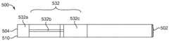
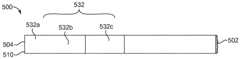
图5示出第四示例气雾生成制品的局部横截面侧视图。5 shows a partial cross-sectional side view of a fourth example aerosol-generating article.
图6示出具有插入的气雾生成制品的示例气雾供应装置的示意横截面视图。Figure 6 shows a schematic cross-sectional view of an example aerosol supply device with an aerosol-generating article inserted.
图7示出用于根据本发明的气雾供应装置中的示例电路的示意表示。Figure 7 shows a schematic representation of an example circuit for use in an aerosol supply device according to the present invention.
具体实施方式Detailed ways
参考图1,示出了气雾生成装置100的纵向横截面视图。气雾生成装置100具有电力室110,该电力室110容纳电源112和用于通过装置100传导能量的传导元件114。在示例中,电源112是电能源,诸如电池,并且电源112可以是例如可再充电电池或一次性电池。导电元件114可以是导线等。在图1中所示的示例中,电力室110朝向装置100的远端102定位。Referring to Figure 1, a longitudinal cross-sectional view of an aerosol-generating
装置100具有容纳控制器122的控制器室120。控制器122基于例如从至少一个传感器(诸如位于装置100中的抽吸传感器(未示出))接收的信息,或基于例如经由用户输入部件140的装置100的用户发出的请求,来控制装置100的操作。装置100被配置为检测至少部分地由电池112、导电元件114和控制器122形成的电路的电特性的变化。
装置100具有朝向装置100的近端104布置的制品接收室130。制品接收室130限定腔室131,制品500可以接收在该腔室131中。制品接收室130包括导电表面132和加热元件134。在图1的示例中,导电表面132是单个导电材料板。在其它示例中,可以使用多于一个的导电表面,例如多于一个的导电板。The
导电表面132用于记录腔室131的局部环境的变化。也就是说,导电表面132用于记录制品500插入到腔室131中,并记录当制品500插入到腔室131中时制品500的电特性的变化。The
导电表面132是电路的一部分,该电路至少部分地由电池112、导电元件114和控制器122形成。导电表面132被配置为当腔室131的局部环境的变化被记录时实现电路的电特性的变化。例如,当将制品500插入腔室131中时,导电表面132被配置为实现电路的电特性的变化。导电表面132被配置为当将制品500插入腔室131中时用户与制品500交互时,引起电路的电特性的变化,如将在下面更详细讨论的。这样,由电源112、导电元件114、控制器122和导电表面132形成的电路形成感测电路,用于感测制品500的插入以及用于感测用户在插入装置100中时与制品500的交互。
导电表面132被布置成受到导电表面132附近的电磁环境的变化的影响。例如,导电表面132可以被布置成受到导电材料插入到腔室131中的影响。当导电表面132受到用户相关交互影响时,诸如在将制品500插入腔室131期间可能发生的用户相关交互影响的情况下,电路的电容会受到影响。The
图1中所示的示例制品500是细长的形式,并且具有插入到腔室131中的远端502和要被接收在用户的嘴中的近端504。制品500具有布置在其近端504处的嘴件510。嘴件510可以具有过滤器等,以用于从用户吸入之前从生成的气雾中选择性地去除组分。在其它示例中,制品500可以不是细长的形式,并且可以采取任何合适的形式,并且可以例如不包括嘴件504。制品500具有导电材料532,在该示例中,该导电材料532沿着制品的长度延伸。在图1的示例中,导电材料532从近端504沿制品500的大部分长度延伸。在其它示例中,导电材料532可沿制品500的长度的任何部分延伸,例如仅沿着制品的长度的一小部分延伸。The
导电材料532被布置为使得在将制品500完全插入装置100中时,将导电材料532的至少一部分布置为靠近装置100的导电表面132,使得导电材料532可以与导电表面132电磁交互。
导电表面132和/或导电材料532可以包括任何合适的导电材料,例如铝、导电墨水或石墨。
在使用中,用户将制品500插入腔室131中,并且导电表面132和导电材料532的至少一部分彼此靠近布置,使得它们可以彼此电磁交互。当以彼此接近的方式布置时,第一导电表面132和第二导电表面532可一起具有第一电容C0。In use, the user inserts the
当用户接触装置100中接收的制品500时,用户改变电路的特性。例如,电路的电容可以通过用户与制品500的交互而变化。该变化可能是由用户接触制品500中的导电材料532并且从而起到制品500电接地的作用,或者由用户以其它方式与导电材料532交互(诸如通过保持制品500使其变形)或通过用户与制品的导电材料532之间的电容耦合效应而引起。由于将导电表面132和导电材料532处的电容例如改变为第二电容值C2,导致用户与导电材料532的交互可以起到改变电路的电容的作用。电容从C0到C2的变化可以由控制器122检测。When the user touches the
利用用户与装置100所接收的制品进行交互的效果,可以允许要产生的电路的电特性的相对较大的变化。例如,可以通过插入不受用户交互显著影响的制品来在电路中产生相对较小的电容变化。在本文所述的示例中,用户与制品500的交互可放大电路中产生的电特性的变化。例如,通过将导电材料532接地或在用户和制品500之间产生电容耦合,与通过插入不受用户交互影响的制品所产生的电容相比,可以产生更大的电路电容变化。较大的变化幅度可以允许更可靠的检测。进而,如将在下面描述的,这可以允许控制器122例如通过提供用于与预定值的列表进行比较的更可靠的值来更准确地确定制品500的特性。Using the effects of user interaction with the article received by
当插入制品500时,控制器122可以将检测到的电容变化与电容值数据库进行比较。以该方式,控制器122可以获得插入制品500是否为预定类型的指示。例如,控制器122可以通过将电容的变化与检测到的第一电容C0(其具有与核准的制品相关联的预定电容值列表)进行比较,来确定制品500是否是由制造商核准与装置100一起使用的制品。如果检测到的电容与预定值列表中的值匹配,则控制器122可以确定制品500被核准使用并且可以被配置为使得能够使用装置100。在优选示例中,控制器122可以被配置为:当检测到的电容指示制品500不被核准使用时,应阻止使用装置100。When inserting the
如上所述,控制器122还被配置为检测由于用户与导电材料532的交互而导致的导电表面132和导电材料532的电容向第二电容值C2的变化。如前一段所述,检测到的电容变化可以用于通过与电容值数据库比较,来提供插入到装置100中的制品500的类型的指示。在优选示例中,由于用户与插入装置中的制品500的交互而引起的电路电容的变化用于确定制品500是否为预定类型,例如,制品500是否是被装置100的制造商核准使用的制品。这取决于所插入的制品500是否被确定为被核准,装置100可以被启用或不被启用。As described above, the
在一些实施方式中,可以向具有不同的可雾化材料(即,提供不同的调味气雾或不同强度的风味/活性物质的材料)的制品提供不同的导电材料,当用户与制品500交互时,该不同的导电材料以不同的方式影响电子电路的特性。例如,电容的某个第一量的变化可以指示可雾化材料的一种风味,而电容的某个第二量的变化可以指示该可雾化材料的另一风味。控制器122可以被配置为不仅检测电容的变化,而且量化电容的变化并将该变化与给定的制品500相关联。控制器122可以使装置能够基于电容变化的幅度来采取不同的动作。In some embodiments, articles with different aerosolizable materials (ie, materials that provide different flavored aerosols or different intensities of flavors/actives) may be provided with different conductive materials when a user interacts with the
在一些示例中,装置100可以经由检测电容的变化来检测用户在将制品500插入装置100中时与制品500接触的时长。在一些示例中,装置100可以通过测量电容的变化并与参考值进行比较来检测用户已经接触了制品500的位置。在一些示例中,装置100可以通过检测与用户的嘴唇的接触以及此类接触的持续时间来推断用户的抽吸持续时间。In some examples,
一旦启用装置100,控制器122就可以指示电源112向加热元件134提供能量。加热元件134可以是电阻、化学或感应加热器等。加热元件134的激活可以基于装置100中的抽吸传感器检测到吸烟时段的开始。可替代地,在装置100已经进入操作状态之后,用户可以经由装置100上的界面140选择加热元件134的激活。可以经由装置100上的界面140向用户通知装置100已经进入操作状态。Once the
在一些示例中,检测到的电容变化可以用于提供用户正在与制品500接触的指示,并且可以起到指示用户正在使用装置100的作用。例如,控制器122可以使用用户对装置100的使用的指示来使装置100保持操作,并且控制器122可以被配置为当在预定的时长内未检测到装置100的使用(通过检测到的电容变化)时,改变装置100的操作的因素。例如,控制器122可以被配置为在装置100检测到用户在诸如4分钟或1分钟的时间段内没有接触到制品500时停用装置100。In some examples, the detected change in capacitance can be used to provide an indication that the user is in contact with the
装置100可能需要以规则的间隔检测与用户接触核准的制品时相关联的电容变化,以使装置100保持操作。可以在吸烟时段所需的典型时间内启用装置100。在示例中,装置100被启用约4分钟。在替代示例中,装置100被启用较短的时间。与使装置100处于较短时间段相关联的优势是,如果尽管使用了未核准的制品,但试图绕开装置100的预防特征导致装置100被启用,则在整个吸烟时段中需要重复进行此类尝试。对于任何试图这样做的人来说,这将使得绕开装置100的预防特征更加麻烦。
在其它示例中,到C2的电容的变化可以充当用于装置的唤醒信号。例如,可以名义上以低功率状态提供该装置(默认情况下或经由硬接通/开关的激活,例如,设置在装置表面上的用户可致动按钮)。在低功率状态中,装置的功能可能受到限制,但是控制器122被配置为检测电容的变化。当用户将制品500插入装置中时,他们接触制品500,并且从而将制品接地。因此,当制品500被完全插入时,控制器122检测到电容C2。控制器122被配置为在首次检测到电容C2时将装置从低功率转换为高功率状态(即装置功能不受限制的状态)。例如,这可能导致向加热器供电,或者可能导致向装置上的显示屏供电。以该方式,装置可以基于对指示用户与制品500交互的某个电容值的检测,从低功率状态转换为高功率状态。In other examples, the change in capacitance to C2 may serve as a wake-up signal for the device. For example, the device may be provided in a nominally low power state (by default or via activation of a hard switch/switch, eg, a user-actuable button provided on the surface of the device). In the low power state, the functionality of the device may be limited, but the
在图2至图5中示出了与图1的装置100一起使用的制品500的示例。图2中所示的制品500具有用于插入图1的装置100的远端502和具有用于插入用户的嘴中的嘴件510的近端504。导电材料532具有多个连接部分532a、532b、532c。An example of an
导电材料532的第一部分532a布置在制品500的近端504处。第一部分532a位于嘴件510附近并且可以围绕嘴件510的一部分。第一部分532a布置成使得当在使用期间将制品500保持在手指或嘴中时,用户可以与表面交互。第一部分532a记录用户与制品500的交互,并且控制器122能检测到变化。A
第一部分532a连接到导电材料532的第二部分532b。第二部分532b是导电材料532的第一部分532a和第三部分532c之间的连接部分。在图2中所示的示例中,第二部分532b比第一部分532a和第三部分532c更薄。第二部分532b传导(pervade,遍及)第一部分532a到第三部分532c的所有变化。The
第三部分532c布置在装置100的导电表面132附近的位置。这可以朝向制品500的中心或朝向制品500的远端502。第三部分532c的大小使得对第一部分532a的电变化被清楚地传递到装置100的第一导电表面132。The
制品500的导电材料532的每个部分可以位于制品500的内部或外部,例如,诸如第三部分532c的部分可以位于制品500的内部,并且可以由制品500的外层(诸如纸外层)包围。导电材料532的部分是否位于内部或外部可能影响发送到装置100的电路的信号的清晰度,而位于外部的导电材料532通常具有更好的信号清晰度。到装置100的电路的信号的清晰度也可能受到导电材料532的各个部分的大小或面积影响。在导电材料532在制品500的外表面上的示例中,与其中导电材料532在制品500内部同时保持可比较的信号清晰度的布置相比,导电材料532的面积可以减小。Each portion of the
在其中导电材料532被配置为由用户直接接触的示例中,第一部分532a不应太小以使用户可以在不接触导电材料532的情况下握住和使用制品500。在图2中所示的示例中,第一部分532a在外部,而第二和第三部分532b、532c在内部。In examples where
现在参考图3,示出了与图1的装置100一起使用的制品500的示例。图3所示的制品500具有与图2中所示的制品500类似的特征。跨示例特征大致相同的情况下,已使用相同的附图标记,并且将不重复描述。Referring now to FIG. 3, an example of an
在图3中所示的示例中,导电材料532的所有三个部分532a、532b、532c都是内部的。如上所述,为了提供相同的信号清晰度,图3中的制品500的第一部分532a在面积上必须比图2中的制品500的第一部分532a更大。在用户和导电部分532之间没有直接接触的地方,例如,因为导电部分532a的部分位于内部,如图3中所示,导电部分对用户交互的检测可以通过用户与导电部分532之间的电容耦合来实现。从用户的角度来看,图3的示例中的第一部分532a的内部放置可能是更期望的,因为制品500将具有普通消耗品的外观。此外,用户可能更优选地用嘴唇触摸具有“正常外观”的嘴件,而不是用导电材料围绕嘴件。诸如在该示例中,内部放置的导电材料532也可以有助于减轻由导电材料拾取的电噪声。In the example shown in Figure 3, all three
现在参考图4,示出了与图1的装置100一起使用的制品500的示例。在图4中所示的示例中,导电材料532的所有三个部分532a、532b、532c都位于外部。如上所述,将导电表面532放置在制品500的外表面上可改善大小相当的导电材料532的信号质量。这可使制造商使用较少的导电材料,同时在使用期间仍保持可接受的信号量。可以将导电材料532结合到诸如设计的美学元素中,以为用户提供视觉上令人愉悦的效果。Referring now to FIG. 4, an example of an
现在参考图5,示出了与图1的装置100一起使用的制品500的示例。导电表面532包括连续的主体,而不是如先前示例中那样具有多个具有不同的大小或宽度的部分。连续体由近端部分532a、中间部分532b和远端部分532c制成,并且可以布置在制品500的外表面上或内部布置,例如在制品500的外部的纸层下方。在内部布置的情况下,需要使用更大面积的导电表面532,以向在外部布置导电材料532的地方提供适当的信号强度。然而,如上所述,内部布置对于用户而言可能在视觉上更令人愉悦。由于需要提供不太复杂的导电表面图案,因此该构造可以具有多个制造优势。Referring now to FIG. 5, an example of an
可以经由布置在杆外部的加热器134,诸如在图1中所示的装置100中,将杆相当均匀地加热。可替代地,制品500可以具有与要与制品500一起使用的装置100的腔体131相对应的任何形状。对制品500的形状的唯一限制是,制品500在使用时应从用户突出到装置100中的导电表面132的适当附近,使得导电材料532可以影响导电表面132。The rod may be heated fairly uniformly via a
还应当理解,上述导电表面不需要形成为连续的环,即,它们不需要在制品500的圆周方向上电连接。例如,导电表面可在制品的外表面周围形成局部环,并在导电表面的端部之间限定间隙(例如,以马蹄型布置)。然而,增加围绕制品500的表面的导电表面的角度范围(或在导电表面不在制品500的外表面的情况下在制品500内)在允许良好的导电耦合方面可能是有利的,但是用户握住制品500。It should also be understood that the conductive surfaces described above need not be formed as a continuous ring, ie, they need not be electrically connected in the circumferential direction of the
现在参考图6,示出了在装置100中使用的制品500的示例。为了提高由控制器122检测到的信号的清洁度,可以为装置100的外壁106选择合适的材料。例如,外壁106可以是连接到电路的导电材料,并且当用户接触外壁106时用于将电路接地。导电表面132可以由绝缘材料(未示出)支撑,以便提高感测电路600的可靠性。电接地组件(未示出)可以位于绝缘材料的背离导电表面132的一侧附近,并且此类组件可以通过例如连接到装置100的导电外壁106而接地。Referring now to FIG. 6, an example of an
现在参考图7,将描述在装置100中使用的示例电路600。电路600具有先前在图1中示出的许多特征。相似的特征以增加500的数字示出,并且在此将不重复对这些特征的讨论。Referring now to FIG. 7, an
图7中所示的电路600具有:控制器622,用于记录电路600的电特性的变化;导电表面632,通过其影响电路600的电特性的变化;以及导电元件614,用于将控制器622连接到导电表面632。控制器622可以是微控制器或微处理器或定时电路,该定时电路在一些示例中可以是模拟定时电路。The
控制器622具有到导电元件614的两个连接点:第一连接点P1和第二连接点P2。电路600还具有布置在导电表面632和到控制器622的第一连接点P1之间的电阻器R1。可选地,电路600还可以具有如图7中灰色所示的电容器C1和电接地650。在电路中包括电容器C1可以改善电路600的可靠性,并改善电路600提供的读数的稳定性和可重复性。The
控制器622能够通过切换第一连接点P1的状态并测量第二连接点P2记录改变的状态所花费的时间来检测电路600的电特性的变化。发生这种情况所需的时间由与电阻器R1的电阻和电路600的电容有关的时间常数确定。因此,电路600能够通过检测电路的时间常数的变化来检测电路的电容的变化。The
电路600的电容包括电容器C1的电容(如果存在的话)和存在于导电表面632上的任何附加电容,诸如当将导电材料532放置成与导电表面632紧密接近时存在的电容。如以上所讨论,用户与导电材料532的交互改变了导电表面132和导电材料532处的电容。The capacitance of
因此,控制器622将例如由于制品500的插入引起的电容变化(变化为C0)或由于用户与导电材料532的交互而引起的电容变化(变化为C2)作为时间常数的变化。也就是说,由于制品500的插入或用户与导电材料532的交互(诸如通过用户的手指或嘴巴与制品500的接触)而引起的电容变化改变了第二连接点P2记录状态变化花费的时间。控制器622可以记下所花费的时间,并且可以将其与时间段的数据库进行比较,控制器622可以包括或可以被提供为电路600的单独组件。数据库中的值可以例如表示与核准的制品相关联的预定时间段,以供装置100使用。当要记录状态变化所花费的时间段在一些预定可接受范围内等于预定时间段时,控制器622已经接收到接收到的制品500被核准并且可以启用装置100的指示。Thus,
控制器622可以控制第一连接点P1的切换。切换可以在使用时段开始之前发生,或者控制器622可以在设置间隔之后切换第一连接点P1。控制器622可以被配置为在整个使用时段中周期性地切换第一连接点P1的状态。例如,控制器622可以在抽吸检测器继续检测到装置100正在使用时继续周期性地切换第一连接点P1的状态。在将制品500插入容纳电路600的装置100中之后,控制器622可以首先根据用户的请求进行切换,并且然后在使用时段期间的各个时间间隔,以确保在整个使用时段中使用核准的消耗品。这将防止被核准的消耗品激活装置100,该消耗品随后在装置100中被未被核准的制品代替。The
以上实施例应被理解为本发明的说明性示例。设想了本发明的其它实施例。应当理解,关于任何一个实施例描述的任何特征可以单独使用,或者与所描述的其它特征结合使用,并且还可以与任何其它实施例的一个或多个特征或任何其它实施例的任何组合结合使用。此外,在不脱离由所附权利要求限定的本发明的范围的情况下,也可以采用以上未描述的等同和修改。The above embodiments should be understood as illustrative examples of the invention. Other embodiments of the present invention are contemplated. It should be understood that any feature described in relation to any one embodiment can be used alone or in combination with other features described and also in combination with one or more features of any other embodiment or in any combination of any other embodiment . Furthermore, equivalents and modifications not described above may also be employed without departing from the scope of the invention as defined by the appended claims.
Claims (24)
Priority Applications (1)
| Application Number | Priority Date | Filing Date | Title |
|---|---|---|---|
| CN202311589087.6ACN117378816A (en) | 2018-03-29 | 2019-03-27 | Aerosol generating device |
Applications Claiming Priority (3)
| Application Number | Priority Date | Filing Date | Title |
|---|---|---|---|
| GB1805234.0 | 2018-03-29 | ||
| GBGB1805234.0AGB201805234D0 (en) | 2018-03-29 | 2018-03-29 | Aerosol generating device |
| PCT/EP2019/057721WO2019185715A1 (en) | 2018-03-29 | 2019-03-27 | Aerosol generating device |
Related Child Applications (1)
| Application Number | Title | Priority Date | Filing Date |
|---|---|---|---|
| CN202311589087.6ADivisionCN117378816A (en) | 2018-03-29 | 2019-03-27 | Aerosol generating device |
Publications (2)
| Publication Number | Publication Date |
|---|---|
| CN111918566Atrue CN111918566A (en) | 2020-11-10 |
| CN111918566B CN111918566B (en) | 2023-12-22 |
Family
ID=62142173
Family Applications (2)
| Application Number | Title | Priority Date | Filing Date |
|---|---|---|---|
| CN201980022425.3AActiveCN111918566B (en) | 2018-03-29 | 2019-03-27 | Aerosol generating device |
| CN202311589087.6APendingCN117378816A (en) | 2018-03-29 | 2019-03-27 | Aerosol generating device |
Family Applications After (1)
| Application Number | Title | Priority Date | Filing Date |
|---|---|---|---|
| CN202311589087.6APendingCN117378816A (en) | 2018-03-29 | 2019-03-27 | Aerosol generating device |
Country Status (17)
| Country | Link |
|---|---|
| US (2) | US11975138B2 (en) |
| EP (2) | EP3799749B1 (en) |
| JP (3) | JP7283684B2 (en) |
| KR (2) | KR102640793B1 (en) |
| CN (2) | CN111918566B (en) |
| AU (3) | AU2019246399B2 (en) |
| BR (1) | BR112020020021A2 (en) |
| CA (2) | CA3208348A1 (en) |
| GB (1) | GB201805234D0 (en) |
| IL (1) | IL277512B2 (en) |
| MX (1) | MX2020010208A (en) |
| MY (1) | MY204680A (en) |
| NZ (1) | NZ768072A (en) |
| PL (1) | PL3799749T3 (en) |
| RU (2) | RU2766080C2 (en) |
| UA (1) | UA128133C2 (en) |
| WO (1) | WO2019185715A1 (en) |
Cited By (1)
| Publication number | Priority date | Publication date | Assignee | Title |
|---|---|---|---|---|
| WO2023165214A1 (en)* | 2022-03-04 | 2023-09-07 | 深圳麦时科技有限公司 | Aerosol generation device and atomization control device thereof |
Families Citing this family (12)
| Publication number | Priority date | Publication date | Assignee | Title |
|---|---|---|---|---|
| GB201805234D0 (en)* | 2018-03-29 | 2018-05-16 | Nicoventures Trading Ltd | Aerosol generating device |
| US12419345B2 (en) | 2020-06-08 | 2025-09-23 | Philip Morris Products S.A. | Aerosol generating article for providing an electrical stimulation to a user |
| WO2022025467A1 (en) | 2020-07-31 | 2022-02-03 | 주식회사 케이티앤지 | Aerosol-generating device comprising electrode |
| CN112595884A (en)* | 2020-12-04 | 2021-04-02 | 昆山联滔电子有限公司 | Replaceable device and detection method thereof |
| KR20220111441A (en)* | 2021-02-02 | 2022-08-09 | 주식회사 이엠텍 | Portable aerosol generating device |
| KR102702978B1 (en)* | 2021-08-27 | 2024-09-05 | 주식회사 케이티앤지 | Aerosol generating device |
| EP4418941A4 (en)* | 2021-10-19 | 2025-08-13 | Kt & G Corp | AEROSOL GENERATION DEVICE |
| KR102688839B1 (en)* | 2021-11-05 | 2024-07-26 | 주식회사 케이티앤지 | Device for generating aerosol |
| KR20240117629A (en)* | 2021-12-28 | 2024-08-01 | 니뽄 다바코 산교 가부시키가이샤 | Non-combustible flavor aspirator |
| KR20240128991A (en)* | 2021-12-28 | 2024-08-27 | 니뽄 다바코 산교 가부시키가이샤 | Non-combustible flavor inhaler |
| WO2024100899A1 (en)* | 2022-11-11 | 2024-05-16 | 日本たばこ産業株式会社 | Non-combustion-type flavor inhaler and capacitive sensor |
| KR20250025139A (en)* | 2023-08-14 | 2025-02-21 | 주식회사 케이티앤지 | Controlling method and aerosol generating device performing the method |
Citations (18)
| Publication number | Priority date | Publication date | Assignee | Title |
|---|---|---|---|---|
| WO1999020940A1 (en)* | 1997-10-20 | 1999-04-29 | Philip Morris Products Inc. | Lighter actuation system |
| CN1541577A (en)* | 2003-04-29 | 2004-11-03 | Non-combustible electronic spray cigarette | |
| US20110277756A1 (en)* | 2010-05-15 | 2011-11-17 | Nathan Andrew Terry | Activation trigger for a personal vaporizing inhaler |
| EP2399636A1 (en)* | 2010-06-23 | 2011-12-28 | Philip Morris Products S.A. | An improved aerosol generator and liquid storage portion for use with the aerosol generator |
| US20130037041A1 (en)* | 2011-08-09 | 2013-02-14 | R. J. Reynolds Tobacco Company | Smoking articles and use thereof for yielding inhalation materials |
| CN103974635A (en)* | 2011-12-08 | 2014-08-06 | 菲利普莫里斯生产公司 | Aerosol generating device with adjustable airflow |
| US20140246020A1 (en)* | 2010-05-15 | 2014-09-04 | Minusa Holdings Llc | Solderless directly written heating elements |
| US20150020825A1 (en)* | 2013-07-19 | 2015-01-22 | R.J. Reynolds Tobacco Company | Electronic smoking article with haptic feedback |
| US20150313287A1 (en)* | 2014-05-01 | 2015-11-05 | Vmr Products Llc | Vaporizer |
| WO2015168828A1 (en)* | 2014-05-04 | 2015-11-12 | 吉瑞高新科技股份有限公司 | Electronic cigarette and atomization control method therefor |
| WO2016009202A1 (en)* | 2014-07-16 | 2016-01-21 | Cambridge Design Partnership Llp | Inhalers |
| US20160158782A1 (en)* | 2014-12-09 | 2016-06-09 | R. J. Reynolds Tobacco Company | Gesture recognition user interface for an aerosol delivery device |
| CN106455707A (en)* | 2014-03-21 | 2017-02-22 | 英美烟草(投资)有限公司 | Apparatus for heating smokable material |
| CA2999210A1 (en)* | 2015-09-24 | 2017-03-30 | Philip Morris Products S.A. | Aerosol-generating system with capacitor |
| JP3212228U (en)* | 2017-06-16 | 2017-08-31 | 株式会社 東亜産業 | Electronic cigarette cartridge using tobacco plant or non-tobacco plant and supporting member thereof |
| US20170258142A1 (en)* | 2016-03-10 | 2017-09-14 | Pax Labs, Inc. | Vaporization device with lip sensing |
| WO2017207442A1 (en)* | 2016-05-31 | 2017-12-07 | Philip Morris Products S.A. | Electrically operated aerosol-generating system with means to detect a tubular aerosol-generating article |
| CN206923669U (en)* | 2014-10-15 | 2018-01-26 | 惠州市吉瑞科技有限公司深圳分公司 | A kind of electronic cigarette |
Family Cites Families (39)
| Publication number | Priority date | Publication date | Assignee | Title |
|---|---|---|---|---|
| US7139328B2 (en)* | 2004-11-04 | 2006-11-21 | Motorola, Inc. | Method and apparatus for closed loop data transmission |
| EP2113178A1 (en) | 2008-04-30 | 2009-11-04 | Philip Morris Products S.A. | An electrically heated smoking system having a liquid storage portion |
| US9439455B2 (en) | 2010-04-30 | 2016-09-13 | Fontem Holdings 4 B.V. | Electronic smoking device |
| SMT202000393T1 (en) | 2010-08-24 | 2020-09-10 | Jt Int Sa | Inhalation device including substance usage controls |
| US20140107815A1 (en) | 2011-09-14 | 2014-04-17 | The Safe Cig, Llc | Electronically augmented container for storing and interfacing with vapor delivery devices |
| BR112014012734B1 (en)* | 2011-12-30 | 2021-03-02 | Philip Morris Products S.A. | aerosol generation system and method for providing aerosol delivery data to an end user |
| JP6062457B2 (en)* | 2011-12-30 | 2017-01-18 | フィリップ・モーリス・プロダクツ・ソシエテ・アノニム | Aerosol generator with airflow detection |
| US9854841B2 (en)* | 2012-10-08 | 2018-01-02 | Rai Strategic Holdings, Inc. | Electronic smoking article and associated method |
| US20140123989A1 (en) | 2012-11-05 | 2014-05-08 | The Safe Cig, Llc | Device and method for vaporizing a fluid |
| US9423152B2 (en)* | 2013-03-15 | 2016-08-23 | R. J. Reynolds Tobacco Company | Heating control arrangement for an electronic smoking article and associated system and method |
| CN105491898B (en) | 2013-03-15 | 2019-02-19 | 奥驰亚客户服务有限责任公司 | Electronic smoking device |
| CA2905091A1 (en)* | 2013-03-15 | 2014-09-25 | Altria Client Services Llc | System and method of obtaining smoking topography data |
| US9560883B2 (en)* | 2013-03-15 | 2017-02-07 | Altria Client Services Llc | Electronic smoking articles |
| KR102343546B1 (en) | 2013-12-03 | 2021-12-28 | 필립모리스 프로덕츠 에스.에이. | Aerosol-generating article and electrically operated system incorporating a taggant |
| CA2876267A1 (en) | 2013-12-31 | 2015-06-30 | Martin Tremblay | Electronic vaping device |
| EP3119218B1 (en)* | 2014-03-19 | 2019-11-06 | Philip Morris Products S.a.s. | Monolithic plane with electrical contacts and methods for manufacturing the same |
| US11147316B2 (en)* | 2014-04-30 | 2021-10-19 | Philip Morris Products S.A. | Aerosol generating device with battery indication |
| US20150320114A1 (en) | 2014-05-12 | 2015-11-12 | Hao Wu | Touch control electronic cigarette |
| KR101776640B1 (en)* | 2014-06-23 | 2017-09-08 | 삼성전자주식회사 | Device for Displaying Identification Information on Other Device and Method thereof |
| WO2016091658A1 (en)* | 2014-12-11 | 2016-06-16 | Philip Morris Products S.A. | Inhaling device with user recognition based on inhalation behaviour |
| PL3236788T3 (en) | 2014-12-25 | 2021-05-17 | Fontem Holdings 1 B.V. | Electronic cigarette liquid detection and measurement systems |
| TWI700997B (en)* | 2015-03-25 | 2020-08-11 | 瑞士商菲利浦莫里斯製品股份有限公司 | Monolithic plane with electrical contacts |
| US10226073B2 (en)* | 2015-06-09 | 2019-03-12 | Rai Strategic Holdings, Inc. | Electronic smoking article including a heating apparatus implementing a solid aerosol generating source, and associated apparatus and method |
| CN105077592B (en) | 2015-07-02 | 2019-03-15 | 天津希格玛微电子技术有限公司 | Electronic cigarette, tobacco rod, smoke grenade and the recognition methods for smoke grenade |
| EP3319466B1 (en) | 2015-07-10 | 2025-08-13 | Juul Labs, Inc. | Wickless vaporizing devices and methods |
| US11033054B2 (en) | 2015-07-24 | 2021-06-15 | Rai Strategic Holdings, Inc. | Radio-frequency identification (RFID) authentication system for aerosol delivery devices |
| EA036828B1 (en)* | 2015-12-22 | 2020-12-24 | Джапан Тобакко Инк. | Power supply assembly, non-combustion-type flavor inhaler and non-combustion-type flavor inhalation system |
| CN108471809B (en)* | 2016-02-09 | 2021-05-14 | 菲利普莫里斯生产公司 | Component for an electrically operated aerosol-generating system having dual functionality |
| US20170231277A1 (en) | 2016-02-12 | 2017-08-17 | Oleg Mironov | Aerosol-generating system with liquid aerosol-forming substrate identification |
| GB201602831D0 (en)* | 2016-02-18 | 2016-04-06 | British American Tobacco Co | Flavour delivery device |
| IL297612B2 (en)* | 2016-05-25 | 2024-06-01 | Juul Labs Inc | Control of an electronic evaporation device |
| CN120531201A (en) | 2016-08-05 | 2025-08-26 | 尤尔实验室有限公司 | Evaporator air speed auxiliary control |
| US20180070634A1 (en) | 2016-09-09 | 2018-03-15 | Rai Strategic Holdings, Inc. | Analog control component for an aerosol delivery device |
| US11660403B2 (en) | 2016-09-22 | 2023-05-30 | Juul Labs, Inc. | Leak-resistant vaporizer device |
| WO2018209632A1 (en)* | 2017-05-18 | 2018-11-22 | 惠州市吉瑞科技有限公司深圳分公司 | Electronic cigarette control method and electronic cigarette |
| US10575562B2 (en) | 2017-06-30 | 2020-03-03 | Rai Strategic Holdings, Inc. | Smoking article for identifying an attribute of an aerosol-generating element for adaptive power output and an associated method |
| CN107568804A (en) | 2017-10-12 | 2018-01-12 | 卓尔悦欧洲控股有限公司 | Cigarette holder, electronic cigarette and its control method |
| GB201805234D0 (en) | 2018-03-29 | 2018-05-16 | Nicoventures Trading Ltd | Aerosol generating device |
| GB201805266D0 (en) | 2018-03-29 | 2018-05-16 | Nicoventures Trading Ltd | Apparatus for generating aerosol from an aerosolisable medium and article of aerosolisable medium |
- 2018
- 2018-03-29GBGBGB1805234.0Apatent/GB201805234D0/ennot_activeCeased
- 2019
- 2019-03-27BRBR112020020021-2Apatent/BR112020020021A2/ennot_activeApplication Discontinuation
- 2019-03-27KRKR1020207028028Apatent/KR102640793B1/enactiveActive
- 2019-03-27AUAU2019246399Apatent/AU2019246399B2/enactiveActive
- 2019-03-27CACA3208348Apatent/CA3208348A1/enactivePending
- 2019-03-27PLPL20204750.2Tpatent/PL3799749T3/enunknown
- 2019-03-27RURU2020135636Apatent/RU2766080C2/enactive
- 2019-03-27MYMYPI2020004868Apatent/MY204680A/enunknown
- 2019-03-27EPEP20204750.2Apatent/EP3799749B1/enactiveActive
- 2019-03-27MXMX2020010208Apatent/MX2020010208A/enunknown
- 2019-03-27WOPCT/EP2019/057721patent/WO2019185715A1/ennot_activeCeased
- 2019-03-27UAUAA202006223Apatent/UA128133C2/enunknown
- 2019-03-27RURU2020131747Apatent/RU2768548C1/enactive
- 2019-03-27NZNZ768072Apatent/NZ768072A/enunknown
- 2019-03-27EPEP19718574.7Apatent/EP3773027A1/enactivePending
- 2019-03-27CNCN201980022425.3Apatent/CN111918566B/enactiveActive
- 2019-03-27CNCN202311589087.6Apatent/CN117378816A/enactivePending
- 2019-03-27KRKR1020247005747Apatent/KR102774268B1/enactiveActive
- 2019-03-27JPJP2020551336Apatent/JP7283684B2/enactiveActive
- 2019-03-27CACA3094956Apatent/CA3094956C/enactiveActive
- 2019-03-27ILIL277512Apatent/IL277512B2/enunknown
- 2019-03-27USUS15/733,695patent/US11975138B2/enactiveActive
- 2020
- 2020-10-30JPJP2020182701Apatent/JP7667649B2/enactiveActive
- 2022
- 2022-11-25AUAU2022275522Apatent/AU2022275522B2/enactiveActive
- 2023
- 2023-03-07JPJP2023034530Apatent/JP7681633B2/enactiveActive
- 2024
- 2024-04-04USUS18/626,403patent/US12377230B2/enactiveActive
- 2024-05-28AUAU2024203575Apatent/AU2024203575A1/ennot_activeAbandoned
Patent Citations (22)
| Publication number | Priority date | Publication date | Assignee | Title |
|---|---|---|---|---|
| WO1999020940A1 (en)* | 1997-10-20 | 1999-04-29 | Philip Morris Products Inc. | Lighter actuation system |
| CN1280661A (en)* | 1997-10-20 | 2001-01-17 | 菲利普莫里斯生产公司 | Lighter actuation system |
| CN1541577A (en)* | 2003-04-29 | 2004-11-03 | Non-combustible electronic spray cigarette | |
| US20060196518A1 (en)* | 2003-04-29 | 2006-09-07 | Lik Hon | Flameless electronic atomizing cigarette |
| US20110277756A1 (en)* | 2010-05-15 | 2011-11-17 | Nathan Andrew Terry | Activation trigger for a personal vaporizing inhaler |
| US20140246020A1 (en)* | 2010-05-15 | 2014-09-04 | Minusa Holdings Llc | Solderless directly written heating elements |
| EP2399636A1 (en)* | 2010-06-23 | 2011-12-28 | Philip Morris Products S.A. | An improved aerosol generator and liquid storage portion for use with the aerosol generator |
| US20130037041A1 (en)* | 2011-08-09 | 2013-02-14 | R. J. Reynolds Tobacco Company | Smoking articles and use thereof for yielding inhalation materials |
| CN103929988A (en)* | 2011-08-09 | 2014-07-16 | R.J.雷诺兹烟草公司 | Smoking articles and their use for producing inhaled substances |
| CN103974635A (en)* | 2011-12-08 | 2014-08-06 | 菲利普莫里斯生产公司 | Aerosol generating device with adjustable airflow |
| US20150020825A1 (en)* | 2013-07-19 | 2015-01-22 | R.J. Reynolds Tobacco Company | Electronic smoking article with haptic feedback |
| CN106455707A (en)* | 2014-03-21 | 2017-02-22 | 英美烟草(投资)有限公司 | Apparatus for heating smokable material |
| US20150313287A1 (en)* | 2014-05-01 | 2015-11-05 | Vmr Products Llc | Vaporizer |
| WO2015168828A1 (en)* | 2014-05-04 | 2015-11-12 | 吉瑞高新科技股份有限公司 | Electronic cigarette and atomization control method therefor |
| WO2016009202A1 (en)* | 2014-07-16 | 2016-01-21 | Cambridge Design Partnership Llp | Inhalers |
| CN206923669U (en)* | 2014-10-15 | 2018-01-26 | 惠州市吉瑞科技有限公司深圳分公司 | A kind of electronic cigarette |
| US20160158782A1 (en)* | 2014-12-09 | 2016-06-09 | R. J. Reynolds Tobacco Company | Gesture recognition user interface for an aerosol delivery device |
| CA2999210A1 (en)* | 2015-09-24 | 2017-03-30 | Philip Morris Products S.A. | Aerosol-generating system with capacitor |
| WO2017051011A1 (en)* | 2015-09-24 | 2017-03-30 | Philip Morris Products S.A. | Aerosol-generating system with capacitor |
| US20170258142A1 (en)* | 2016-03-10 | 2017-09-14 | Pax Labs, Inc. | Vaporization device with lip sensing |
| WO2017207442A1 (en)* | 2016-05-31 | 2017-12-07 | Philip Morris Products S.A. | Electrically operated aerosol-generating system with means to detect a tubular aerosol-generating article |
| JP3212228U (en)* | 2017-06-16 | 2017-08-31 | 株式会社 東亜産業 | Electronic cigarette cartridge using tobacco plant or non-tobacco plant and supporting member thereof |
Cited By (1)
| Publication number | Priority date | Publication date | Assignee | Title |
|---|---|---|---|---|
| WO2023165214A1 (en)* | 2022-03-04 | 2023-09-07 | 深圳麦时科技有限公司 | Aerosol generation device and atomization control device thereof |
Also Published As
Similar Documents
| Publication | Publication Date | Title |
|---|---|---|
| CN111918566B (en) | Aerosol generating device | |
| JP7595102B2 (en) | Aerosol generating device | |
| JP6348985B2 (en) | Apparatus for heating smoking material and article for smoking material | |
| KR102032102B1 (en) | Aerosol generating device with air flow detection | |
| CN111511233A (en) | Aerosol generating device and operation method thereof | |
| KR102850538B1 (en) | Aerosol generating device | |
| CN118450823A (en) | Aerosol supply device with humidity sensor | |
| EP4369968B1 (en) | Air pressure measurement to detect an obstruction in an airflow path | |
| JP2024515069A (en) | Method for determining the dielectric response of an aerosol-generating article |
Legal Events
| Date | Code | Title | Description |
|---|---|---|---|
| PB01 | Publication | ||
| PB01 | Publication | ||
| SE01 | Entry into force of request for substantive examination | ||
| SE01 | Entry into force of request for substantive examination | ||
| GR01 | Patent grant | ||
| GR01 | Patent grant |