CN111913050B - Contact type electric thickness reflection measurement probe and method suitable for non-planar radome - Google Patents
Contact type electric thickness reflection measurement probe and method suitable for non-planar radomeDownload PDFInfo
- Publication number
- CN111913050B CN111913050BCN202010831700.0ACN202010831700ACN111913050BCN 111913050 BCN111913050 BCN 111913050BCN 202010831700 ACN202010831700 ACN 202010831700ACN 111913050 BCN111913050 BCN 111913050B
- Authority
- CN
- China
- Prior art keywords
- waveguide
- radome
- planar
- reflection measurement
- contact
- Prior art date
- Legal status (The legal status is an assumption and is not a legal conclusion. Google has not performed a legal analysis and makes no representation as to the accuracy of the status listed.)
- Active
Links
Images


Classifications
- G—PHYSICS
- G01—MEASURING; TESTING
- G01R—MEASURING ELECTRIC VARIABLES; MEASURING MAGNETIC VARIABLES
- G01R29/00—Arrangements for measuring or indicating electric quantities not covered by groups G01R19/00 - G01R27/00
- G01R29/08—Measuring electromagnetic field characteristics
- G01R29/10—Radiation diagrams of antennas
- G—PHYSICS
- G01—MEASURING; TESTING
- G01B—MEASURING LENGTH, THICKNESS OR SIMILAR LINEAR DIMENSIONS; MEASURING ANGLES; MEASURING AREAS; MEASURING IRREGULARITIES OF SURFACES OR CONTOURS
- G01B7/00—Measuring arrangements characterised by the use of electric or magnetic techniques
- G01B7/02—Measuring arrangements characterised by the use of electric or magnetic techniques for measuring length, width or thickness
- G01B7/06—Measuring arrangements characterised by the use of electric or magnetic techniques for measuring length, width or thickness for measuring thickness
- G—PHYSICS
- G01—MEASURING; TESTING
- G01R—MEASURING ELECTRIC VARIABLES; MEASURING MAGNETIC VARIABLES
- G01R29/00—Arrangements for measuring or indicating electric quantities not covered by groups G01R19/00 - G01R27/00
- G01R29/08—Measuring electromagnetic field characteristics
- G01R29/0864—Measuring electromagnetic field characteristics characterised by constructional or functional features
- G01R29/0878—Sensors; antennas; probes; detectors
Landscapes
- Physics & Mathematics (AREA)
- General Physics & Mathematics (AREA)
- Electromagnetism (AREA)
- Radar Systems Or Details Thereof (AREA)
- Details Of Aerials (AREA)
Abstract
Description
Translated fromChinese技术领域technical field
本公开涉及电厚度测试技术领域,特别涉及一种适用于非平面天线罩的接触式电厚度反射测量探头及方法。The disclosure relates to the technical field of electrical thickness testing, in particular to a contact-type electrical thickness reflection measurement probe and method suitable for non-planar radome.
背景技术Background technique
本部分的陈述仅仅是提供了与本公开相关的背景技术,并不必然构成现有技术。The statements in this section merely provide background information related to the present disclosure and may not necessarily constitute prior art.
电厚度是指电磁波辐射穿越非真空介质空间时,相对于同样几何尺寸的真空路径增加的波数,可等效为电磁波在介质中传播相对于真空增加的相位延迟,称为插入相位延迟(IPD)。IPD参数对于雷达天线罩的设计具有重要的意义,也是天线罩制造过程控制和成品检验的重要参数。IPD测量分为透射法和反射法,前者将测试收发天线分置在天线罩内外两侧,通过比对有无天线罩时的电磁波传输相位差测量;后者则是将收发天线都放在天线罩外侧,在天线罩内壁放置共形反射面,通过反射让电磁波两次穿过天线罩,比对反射信号的相位差可以以两倍的灵敏度获得IPD信息。Electric thickness refers to the increase in wave number relative to the vacuum path of the same geometric size when the electromagnetic wave radiation passes through the non-vacuum medium space, which can be equivalent to the phase delay of the electromagnetic wave propagating in the medium relative to the vacuum increase, called insertion phase delay (IPD) . The IPD parameter is of great significance to the design of the radome, and it is also an important parameter for the control of the radome manufacturing process and the inspection of the finished product. IPD measurement is divided into transmission method and reflection method. The former places the test transceiver antenna on the inside and outside of the radome, and measures the electromagnetic wave transmission phase difference with or without the radome; the latter puts the transceiver antenna on the antenna. On the outside of the radome, place a conformal reflector on the inner wall of the radome, and let the electromagnetic wave pass through the radome twice through reflection. By comparing the phase difference of the reflected signal, IPD information can be obtained with twice the sensitivity.
以测试天线是否接触天线罩区分,反射测试还可以分为接触式和非接触式两种。非接触式由于天线探头与天线罩的距离难以精确控制,在微波频段测量时难以保证精度;接触式一般采用收发双工天线探头,直接抵在天线罩上,不存在距离误差问题。To distinguish whether the test antenna is in contact with the radome, the reflection test can also be divided into two types: contact type and non-contact type. Since the distance between the antenna probe and the radome of the non-contact type is difficult to accurately control, it is difficult to guarantee the accuracy when measuring in the microwave frequency band; the contact type generally uses a transceiver duplex antenna probe, which directly touches the radome, and there is no distance error problem.
但是本公开发明人发现,对于大部分天线罩来说,其被测区域表面都不是平面,特别是外表面往往是凸面,而常用测试探头如微波波导口,抵在天线罩表面虽然可以保证没有纵向距离误差,却难以保证与天线罩表面法线夹角的重复性和稳定性,从而导致IPD测量的不确定性。However, the inventors of the present disclosure have found that for most radomes, the surface of the measured area is not flat, especially the outer surface is often convex, and the commonly used test probes, such as microwave waveguide ports, can guarantee that there is no Longitudinal distance error, but it is difficult to ensure the repeatability and stability of the angle with the surface normal of the radome, which leads to the uncertainty of IPD measurement.
如图1所示,常用的矩形微波波导是内壁宽边为a、窄边为b的金属腔体管道,横截面如图中右上角的粗实线矩形,电磁波在波导腔体内沿L方向传输,场强和能量沿宽边分别按正弦和升余弦规律分布,如其中的虚线和实线所示,中间最大,靠近短边后衰减为零。电场矢量E方向平行短边,垂直于宽边。波导管的俯视图上部中间粗实线矩形所示,标记长度为L;侧视图如左上角粗实线矩形所示。As shown in Figure 1, the commonly used rectangular microwave waveguide is a metal cavity pipe with the inner wall having a wide side as a and a narrow side as b. The cross section is a rectangle with a thick solid line in the upper right corner of the figure. , the field strength and energy are distributed according to the law of sine and raised cosine respectively along the broad side, as shown by the dotted line and the solid line, the maximum in the middle, and attenuation to zero near the short side. The direction of the electric field vector E is parallel to the short side and perpendicular to the broad side. The top view of the waveguide is shown by the thick solid line rectangle in the upper middle, and the marked length is L; the side view is shown by the thick solid line rectangle in the upper left corner.
图中下方是非平面天线罩局部示意图,灰色是介质天线罩,黑色是天线罩内壁的共形反射面,如制造过程中的金属胎。IPD测量目标是是获得电磁信号垂直穿越天线罩造成的相位变化,该相位变化与天线罩厚度成比例,比例系数由天线罩材料决定。The bottom part of the figure is a partial schematic diagram of a non-planar radome, the gray is a dielectric radome, and the black is a conformal reflective surface on the inner wall of the radome, such as a metal tire in the manufacturing process. The goal of IPD measurement is to obtain the phase change caused by the electromagnetic signal vertically passing through the radome. The phase change is proportional to the thickness of the radome, and the proportional coefficient is determined by the material of the radome.
理想测试条件下,电磁波从俯视图波导管上端口向下传输,到达下端口,然后垂直进入天线罩,到达内壁后反射,沿原路径返回波导上端口。在波导上端口利用矢量反射计可以测量获得电磁波整个传输路径的相位变化,扣除波导管内传输对应相位变化(可理论计算或事先校准获得)就可以得到电磁波穿越天线罩的相位变化,即IPD。该方法也可以用于比较不同天线罩的IPD。Under ideal test conditions, the electromagnetic wave is transmitted downward from the upper port of the waveguide in the top view, reaches the lower port, then enters the radome vertically, reaches the inner wall and reflects, and returns to the upper port of the waveguide along the original path. The phase change of the entire transmission path of the electromagnetic wave can be measured by using a vector reflectometer at the upper port of the waveguide, and the phase change of the electromagnetic wave passing through the radome can be obtained by deducting the corresponding phase change of transmission in the waveguide (which can be obtained by theoretical calculation or calibration in advance), that is, IPD. This method can also be used to compare the IPD of different radomes.
但是由于波导口平面和非平面天线罩之间是非稳定接触,特别是凸表面点接触情况下,很难保证波导轴线与预期接触点表面法线的平行,微小的角度偏差就会导致测量数据的明显偏差,从而导致测量精度下降,不具备可重复性。比如波导口探头在曲率半径为R的天线罩凸表面上偏转角度θ,就会导致预期接触点O沿天线罩表面横向偏移距离l1=Rθ,挪移到O’,作为预期接触点的波导口面几何中心,则离开天线罩表面距离l2=R-Rcosθ+l1sinθ=R(1-cosθ+θsinθ)≈Rθ2。无论是l1导致的有效接触点变化,还是l2导致的电磁波传输路径变长,都导致了测量精度下降和可重复性恶化。However, due to the unstable contact between the plane of the waveguide and the non-planar radome, especially in the case of point contact on the convex surface, it is difficult to ensure that the axis of the waveguide is parallel to the normal of the surface of the expected contact point, and a small angle deviation will lead to the measurement data. Obvious deviation, resulting in a decrease in measurement accuracy and non-repeatability. For example, the deflection angle θ of the waveguide mouth probe on the convex surface of the radome with the radius of curvature R will cause the expected contact point O to shift laterally along the surface of the radome by a distance l1 = Rθ, and move to O', as the waveguide of the expected contact point For the geometric center of the mouth surface, the distance from the surface of the radome is l2 =R-Rcosθ+l1 sinθ=R(1-cosθ+θsinθ)≈Rθ2 . Whether it is the change of the effective contact point caused by l1 or the lengthening of the electromagnetic wave transmission path caused by l2 , it leads to the decrease of measurement accuracy and the deterioration of repeatability.
为了防止上述误差的发生,传统的方法要么是采用精密定位系统,如高精度多维度控制机器手,确保探头能够精确垂直贴合在天线罩表面;要么在探头上附加定位状态感知系统,在测量过程中不断检测探头与天线罩表面的相对角度,在试探过程中只记录相对角度测量参数一致时的IPD测量数据;要么将波导口周边的波导壁向内开槽,只保留三个突出的接触点,确保接触角度稳固。In order to prevent the occurrence of the above errors, the traditional method is either to use a precision positioning system, such as a high-precision multi-dimensional control robot arm, to ensure that the probe can be accurately and vertically attached to the surface of the radome; or to attach a positioning state perception system to the probe to measure During the process, the relative angle between the probe and the surface of the radome is continuously detected, and only the IPD measurement data when the relative angle measurement parameters are consistent are recorded during the trial process; or the waveguide wall around the waveguide mouth is grooved inward, and only three protruding contacts are kept point to ensure a firm contact angle.
但是,采用高精度多维度控制机器手实现探头精确垂直贴合在天线罩表面,最大的问题是设备复杂,代价高昂;采用实时姿态测量系统,最大的问题是该方法本身不能解决对正问题,只能引导和标记对正试探过程,降低了测量速度,而且辅助显示装置本身也比较复杂,影响了测试方便性;波导壁向内开槽方法简便易行,但是以三个触点保证相对姿态为目标,却破坏了测试探头电磁场有效分布,导致了电信号测量的不确定性。However, using a high-precision multi-dimensional control robot to achieve precise vertical attachment of the probe to the surface of the radome, the biggest problem is that the equipment is complex and expensive; using a real-time attitude measurement system, the biggest problem is that the method itself cannot solve the alignment problem. It can only guide and mark the alignment trial process, which reduces the measurement speed, and the auxiliary display device itself is relatively complicated, which affects the convenience of the test; the method of slotting the waveguide wall inward is simple and easy, but the relative attitude is guaranteed by three contacts As the target, it destroys the effective distribution of the electromagnetic field of the test probe, which leads to the uncertainty of the electrical signal measurement.
发明内容Contents of the invention
为了解决现有技术的不足,本公开提供了一种适用于非平面天线罩的接触式电厚度反射测量探头及方法,不再寻求接触角度的可重复性,使得探头测试效果在一定范围内不依赖于接触角度,既方便测量,又能保证测量精度和可重复性。In order to solve the deficiencies of the prior art, the present disclosure provides a contact-type electrical thickness reflection measurement probe and method suitable for non-planar radome, without seeking the repeatability of the contact angle, so that the probe test effect is not different within a certain range Depending on the contact angle, it not only facilitates measurement, but also ensures measurement accuracy and repeatability.
为了实现上述目的,本公开采用如下技术方案:In order to achieve the above purpose, the present disclosure adopts the following technical solutions:
本公开第一方面提供了一种适用于非平面天线罩的接触式电厚度反射测量探头。The first aspect of the present disclosure provides a contact-type electrical thickness reflection measurement probe suitable for non-planar radome.
一种适用于非平面天线罩的接触式电厚度反射测量探头,包括波导本体,波导本体的测试端面上设有两个由侧壁延伸成的相对波导本体轴线对称的突出部,每个凸出部包括用于与非平面天线罩接触的端点。A contact-type electrical thickness reflection measurement probe suitable for non-planar radome, comprising a waveguide body, the test end surface of the waveguide body is provided with two protrusions extending from the side walls that are symmetrical to the axis of the waveguide body, each protruding The portion includes an end point for contact with a non-planar radome.
作为可能的一些实现方式,所述凸出部为波导本体的侧壁向外延伸且沿垂直于轴线的方向收缩到一个端点形成。As some possible implementation manners, the protruding portion is formed by the sidewall of the waveguide body extending outward and shrinking to an end point along a direction perpendicular to the axis.
作为可能的一些实现方式,所述端点为尖锐端点,且突出部朝波导本体轴线方向倾斜。As some possible implementation manners, the end point is a sharp end point, and the protrusion is inclined toward the axis of the waveguide body.
作为可能的一些实现方式,所述端点为尖锐端点,且突出部朝远离波导本体轴线的方向倾斜。As some possible implementation manners, the end point is a sharp end point, and the protrusion is inclined in a direction away from the axis of the waveguide body.
作为可能的一些实现方式,所述端点为尖锐端点,且突出部的朝向与波导本体的轴线平行。As some possible implementation manners, the end point is a sharp end point, and the direction of the protrusion is parallel to the axis of the waveguide body.
作为可能的一些实现方式,所述端点采用圆弧等方式将尖锐端点局部倒角修平得到。As some possible implementation manners, the end point is obtained by rounding off the sharp end point with local chamfering by way of circular arc or the like.
作为可能的一些实现方式,所述波导本体包括且不限于矩形波导、减高波导、脊波导、圆波导或椭圆波导中的一种。As some possible implementation manners, the waveguide body includes, but is not limited to, one of a rectangular waveguide, a height-reduced waveguide, a ridge waveguide, a circular waveguide, or an elliptical waveguide.
作为可能的一些实现方式,所述波导本体为测试端面为矩形的矩形波导,测试端面的两条长边分别延伸出一个凸出部,且所述端点位于长边所在侧壁的中线延长线上。As some possible implementations, the waveguide body is a rectangular waveguide with a rectangular test end face, two long sides of the test end face respectively extend a protrusion, and the end point is located on the extension line of the midline of the side wall where the long side is located .
作为可能的一些实现方式,所述凸出部的底边为测试端面的长边。As some possible implementation manners, the bottom side of the protrusion is the long side of the test end face.
作为可能的一些实现方式,两个凸出部结构相同,且相对波导本体的轴线对称设置。As some possible implementation manners, the two protrusions have the same structure and are arranged symmetrically with respect to the axis of the waveguide body.
作为进一步的限定,测试端面的短边保持原配置,两个凸出部之间的空间的两侧对自由空间开放。As a further limitation, the short side of the test end face remains in the original configuration, and the space between the two protrusions is open to free space on both sides.
电磁波在矩形波导的腔体内沿波导轴线方向传播,场强沿测试端面的长边按正弦规律分布,能量沿测试端面的长边方向按升余弦规律分布,电场矢量方向平行于测试端面的短边且垂直于长边。The electromagnetic wave propagates along the axis of the waveguide in the cavity of the rectangular waveguide, the field strength is distributed along the long side of the test end face according to the law of sine, the energy is distributed according to the law of raised cosine along the long side of the test end face, and the direction of the electric field vector is parallel to the short side of the test end face and perpendicular to the long side.
作为可能的一些实现方式,通过改变突出部的延伸长度和/或突出部的收窄渐变方式进行诱导效果的改变。As some possible implementation manners, the inductive effect is changed by changing the extension length of the protrusion and/or the gradual narrowing mode of the protrusion.
作为可能的一些实现方式,通过改变两个突出部的端点之间的距离进行诱导效果的改变。As some possible implementation manners, the inductive effect is changed by changing the distance between the end points of the two protrusions.
本公开第二方面提供了一种适用于非平面天线罩的接触式电厚度反射测量装置,包括本公开第一方面所述的适用于非平面天线罩的接触式电厚度反射测量探头。The second aspect of the present disclosure provides a contact-type electrical thickness reflection measurement device suitable for non-planar radome, including the contact-type electrical thickness reflection measurement probe suitable for non-planar radome described in the first aspect of the present disclosure.
本公开第三方面提供了一种适用于非平面天线罩的接触式电厚度反射测量方法,利用本公开第一方面所述的适用于非平面天线罩的接触式电厚度反射测量探头;The third aspect of the present disclosure provides a contact-type electrical thickness reflection measurement method suitable for non-planar radome, using the contact-type electrical thickness reflection measurement probe suitable for non-planar radome described in the first aspect of the present disclosure;
将两个凸出部的端点与待测非平面天线罩接触;Contact the end points of the two protrusions with the non-planar radome to be tested;
突出部诱导波导中传输的能量向端点集中,形成以端点为相位中心的前向辐射;The protruding part induces the energy transmitted in the waveguide to concentrate toward the end point, forming forward radiation with the end point as the phase center;
所述前向辐射穿透天线罩,经过内壁反射后回到探头端点,按照原路径返回波导,通过反射系数的相位变化得到天线罩的电厚度参数。The forward radiation penetrates the radome, returns to the end point of the probe after being reflected by the inner wall, returns to the waveguide according to the original path, and obtains the electrical thickness parameter of the radome through the phase change of the reflection coefficient.
作为可能的一些实现方式,所述测量探头可以以两端点的连线为轴线进行摆动,摆动范围在±10°以内不会造成明显的测量不确定性。As some possible implementation manners, the measurement probe can be oscillated around the axis connecting the two ends, and the oscillating range will not cause obvious measurement uncertainty within ±10°.
与现有技术相比,本公开的有益效果是:Compared with the prior art, the beneficial effects of the present disclosure are:
1、本公开提供的探头、装置及方法,通过波导本体的测试端面上设置两个由侧壁延伸成的相对波导本体轴线对称的突出部,诱导测试信号传输能量分布,形成以接触点轴心为相位中心的电磁波辐射,既保证了探头与被测天线罩接触点的可重复性,又使得IPD反射测试信号对探头摆动不敏感。1. The probe, device and method provided by the present disclosure set two protruding parts extending from the side walls symmetrical to the axis of the waveguide body on the test end surface of the waveguide body to induce the energy distribution of the test signal transmission to form a contact point axis center The electromagnetic radiation of the phase center not only ensures the repeatability of the contact point between the probe and the radome under test, but also makes the IPD reflection test signal insensitive to the probe swing.
2、本公开提供的探头、装置及方法,通过波导壁的延伸和收窄,引导测试信号能量集中到尖部,并以尖部作为接触点并形成辐射相位中心,极大的提高了测试的稳定性。2. The probe, device and method provided by the present disclosure guide the energy of the test signal to the tip through the extension and narrowing of the waveguide wall, and use the tip as a contact point to form a radiation phase center, which greatly improves the testing efficiency. stability.
3、本公开提供的探头、装置及方法,采用双接触点实现非平面天线罩接触式反射测量,经济简单,易于精确定位。测试结果对探头唯一的摆动自由度不敏感,在便于自然控制的摆动范围内保证了IPD测量精度和可重复性。3. The probe, device and method provided by the present disclosure use double contact points to realize non-planar radome contact reflection measurement, which is economical and simple, and easy for precise positioning. The test result is insensitive to the only swing degree of freedom of the probe, and the IPD measurement accuracy and repeatability are guaranteed within the swing range that is convenient for natural control.
附图说明Description of drawings
构成本公开的一部分的说明书附图用来提供对本公开的进一步理解,本公开的示意性实施例及其说明用于解释本公开,并不构成对本公开的不当限定。The accompanying drawings constituting a part of the present disclosure are used to provide a further understanding of the present disclosure, and the exemplary embodiments and descriptions of the present disclosure are used to explain the present disclosure, and do not constitute improper limitations to the present disclosure.
图1为本公开背景技术中提供的矩形波导探头测试的示意图。FIG. 1 is a schematic diagram of testing a rectangular waveguide probe provided in the background art of the present disclosure.
图2为本公开实施例1提供的适用于非平面天线罩的接触式电厚度反射测量探头的测试示意图。FIG. 2 is a schematic diagram of testing a contact-type electrical thickness reflection measuring probe suitable for a non-planar radome provided by Embodiment 1 of the present disclosure.
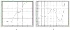
图3为本公开实施例1提供的测量误差与摆动角度的对应关系示意图。FIG. 3 is a schematic diagram of the corresponding relationship between the measurement error and the swing angle provided by Embodiment 1 of the present disclosure.
具体实施方式Detailed ways
下面结合附图与实施例对本公开作进一步说明。The present disclosure will be further described below in conjunction with the accompanying drawings and embodiments.
应该指出,以下详细说明都是例示性的,旨在对本公开提供进一步的说明。除非另有指明,本文使用的所有技术和科学术语具有与本公开所属技术领域的普通技术人员通常理解的相同含义。It should be noted that the following detailed description is exemplary and intended to provide further explanation of the present disclosure. Unless defined otherwise, all technical and scientific terms used herein have the same meaning as commonly understood by one of ordinary skill in the art to which this disclosure belongs.
需要注意的是,这里所使用的术语仅是为了描述具体实施方式,而非意图限制根据本公开的示例性实施方式。如在这里所使用的,除非上下文另外明确指出,否则单数形式也意图包括复数形式,此外,还应当理解的是,当在本说明书中使用术语“包含”和/或“包括”时,其指明存在特征、步骤、操作、器件、组件和/或它们的组合。It should be noted that the terminology used herein is only for describing specific embodiments, and is not intended to limit the exemplary embodiments according to the present disclosure. As used herein, unless the context clearly dictates otherwise, the singular is intended to include the plural, and it should also be understood that when the terms "comprising" and/or "comprising" are used in this specification, they mean There are features, steps, operations, means, components and/or combinations thereof.
在本公开中,术语如“上”、“下”、“左”、“右”、“前”、“后”、“竖直”、“水平”、“侧”、“底”等指示的方位或位置关系为基于附图所示的方位或位置关系,只是为了便于叙述本公开各部件或元件结构关系而确定的关系词,并非特指本公开中任一部件或元件,不能理解为对本公开的限制。In this disclosure, terms such as "upper", "lower", "left", "right", "front", "rear", "vertical", "horizontal", "side", "bottom" etc. refer to The orientation or positional relationship is based on the orientation or positional relationship shown in the drawings, and is only a relative term determined for the convenience of describing the structural relationship between the components or elements of the present disclosure. Public restrictions.
本公开中,术语如“固接”、“相连”、“连接”等应做广义理解,表示可以是固定连接,也可以是一体地连接或可拆卸连接;可以是直接相连,也可以通过中间媒介间接相连。对于本领域的相关科研或技术人员,可以根据具体情况确定上述术语在本公开中的具体含义,不能理解为对本公开的限制。In this disclosure, terms such as "fixed", "connected", and "connected" should be interpreted in a broad sense, which means that they can be fixedly connected, integrally connected or detachably connected; they can be connected directly or through an intermediate connection. The medium is indirectly connected. For relevant researchers or technicians in the field, the specific meanings of the above terms in the present disclosure can be determined according to specific situations, and should not be construed as limitations on the present disclosure.
在不冲突的情况下,本公开中的实施例及实施例中的特征可以相互组合。In the case of no conflict, the embodiments in the present disclosure and the features in the embodiments can be combined with each other.
实施例1:Example 1:
本公开实施例1提供了一种适用于非平面天线罩的接触式电厚度反射测量探头,包括波导本体,波导本体的测试端面上设有两个由侧壁延伸成的相对波导本体轴线对称设置的突出部,每个凸出部包括用于与非平面天线罩接触的端点。Embodiment 1 of the present disclosure provides a contact-type electrical thickness reflection measurement probe suitable for non-planar radome, including a waveguide body, and two test end surfaces of the waveguide body are arranged symmetrically with respect to the axis of the waveguide body extending from the side wall protrusions, each protrusion including an end point for contacting the non-planar radome.
所述凸出部为波导本体的侧壁向外延伸且沿垂直于轴线的方向收缩到一个端点形成。The protruding portion is formed by the sidewall of the waveguide body extending outward and shrinking to an end point along a direction perpendicular to the axis.
本实施例中,所述端点为尖锐端点,且突出部上的尖锐端点朝向与波导本体的轴向平行。In this embodiment, the end point is a sharp end point, and the sharp end point on the protrusion is oriented parallel to the axial direction of the waveguide body.
可以理解的,在其他一些实施方式中,所述突出部上的尖锐端点朝波导本体轴线的方向倾斜,可以增强能量诱导汇聚效果;或者突出部上的尖锐端点的朝远离波导本体轴线的方向倾斜,可以增强对外辐射效果,本领域技术人员可以根据具体工况进行选择,这里不再赘述。It can be understood that, in some other embodiments, the sharp end point on the protrusion is inclined toward the axis of the waveguide body, which can enhance the energy-induced convergence effect; or the sharp end point on the protrusion is inclined away from the axis of the waveguide body , can enhance the effect of external radiation, those skilled in the art can choose according to the specific working conditions, and will not repeat them here.
本实施例中以矩形波导为例进行介绍,当然可以理解的,在其他一些实施方式中,所述波导本体包括且不限于矩形波导、减高波导、脊波导、圆波导或椭圆波导中的一种。In this embodiment, a rectangular waveguide is taken as an example for introduction. Of course, it can be understood that in some other implementation manners, the waveguide body includes but is not limited to one of a rectangular waveguide, a reduced-height waveguide, a ridge waveguide, a circular waveguide, or an elliptical waveguide. kind.
本实施例中,如图2所示,以矩形波导探头为基础,在原平面波导测试端面的基础上,将宽边向前延伸H,两侧逐渐收缩,形成往前的渐变凸起。上下宽边对应延伸,凸起形成“鸟嘴”形状,如图中粗实线所示,比图1的现有技术的方案多出了延伸出来的尖锐部分。In this embodiment, as shown in FIG. 2 , based on the rectangular waveguide probe, and on the basis of the test end face of the original planar waveguide, the wide side is extended forward H, and the two sides are gradually shrunk to form a forward gradient protrusion. The upper and lower wide sides extend correspondingly, and the protrusions form a "bird's beak" shape, as shown by the thick solid line in the figure, which has more extended sharp parts than the prior art solution in Fig. 1 .
与被测天线罩接触时只有两个突出接触点,非常易于测试点定位,不会发生探测点的不可重复性;探头与天线罩表面之间只有一个空间几何状态相对自由度,即围绕两个接触点的连线为轴旋转,而有限的旋转角不影响IP测量精度,从而保证了IPD测量的便捷性和可重复性。There are only two protruding contact points when in contact with the radome under test, which is very easy to locate the test point, and the non-repeatability of the detection point will not occur; there is only one relative degree of freedom of the spatial geometric state between the probe and the surface of the radome, that is, around two The connecting line of the contact point is the axis rotation, and the limited rotation angle does not affect the IP measurement accuracy, thus ensuring the convenience and repeatability of IPD measurement.
所述矩形波导探头为测试端面为矩形的矩形波导,测试端面的两条长边分别延伸出一个凸出部,且所述端点位于长边所在侧壁的中线延长线上。The rectangular waveguide probe is a rectangular waveguide with a rectangular test end surface, two long sides of the test end surface respectively extend a protrusion, and the end points are located on the extension line of the midline of the side wall where the long sides are located.
所述凸出部的底边为测试端面的长边,凸出部在长边所在侧壁的所在平面上的投影为等腰三角形,端点为等腰三角形状凸出部的顶点。The base of the protruding portion is the long side of the test end face, the projection of the protruding portion on the plane of the side wall where the long side is located is an isosceles triangle, and the end point is the apex of the isosceles triangle-shaped protruding portion.
可以理解的,在其他一些实施方式中,所述突出部可以是任意弯曲或者曲折的形状,可以是其他三角形或者锥形结构,只要存在一个尖锐端点且两个突出部对称设置即可,本领域技术人员可以根据具体工况进行选择以实现诱导汇聚效果的改变,这里不再赘述It can be understood that, in some other embodiments, the protruding part can be in any curved or zigzag shape, and can be other triangular or conical structures, as long as there is a sharp end point and the two protruding parts are arranged symmetrically. Technicians can choose according to the specific working conditions to realize the change of induced convergence effect, so I won’t go into details here
本实施例中,两个凸出部结构相同,且正对设置,可以通过改变两个突出部的端点的相对距离,以形成不同的诱导效果,本领域技术人员可以根据具体工况进行相对距离的选择,这里不再赘述。In this embodiment, the two protrusions have the same structure and are arranged facing each other. Different inductive effects can be formed by changing the relative distance between the endpoints of the two protrusions. Those skilled in the art can adjust the relative distance according to specific working conditions. selection, which will not be repeated here.
测试端面的短边保持原配置,即凸出部没有短边金属侧壁,两个凸出部之间的空间的两侧对自由空间开放。The short side of the test end face remains in the original configuration, that is, the protrusions have no short side metal side walls, and the two sides of the space between the two protrusions are open to free space.
本实施例中,电磁波在矩形波导的腔体内沿与测试端面垂直的方向传播,场强沿测试端面的长边按正弦规律分布,能量沿测试端面的长边方向按升余弦规律分布,电场矢量方向平行于测试端面的短边且垂直于长边。In this embodiment, the electromagnetic wave propagates in the cavity of the rectangular waveguide along the direction perpendicular to the test end face, the field strength is distributed according to the sine law along the long side of the test end face, the energy is distributed according to the raised cosine law along the long side direction of the test end face, and the electric field vector The direction is parallel to the short side of the test end face and perpendicular to the long side.
矩形波导内的电场强度分布按正弦规律横向分布,能量以升余弦分布集中在宽边中间。本实施例提出的延伸突出结构,在测试端口处将能量进一步向中心集中,形成以尖端为相位中心的前向辐射。该辐射穿透天线罩,经过内壁反射后回到探头端点,按照原路径返回波导,通过反射系数相位变化体现天线罩的电厚度参数IPD。The electric field intensity distribution in the rectangular waveguide is distributed laterally according to the law of sine, and the energy is concentrated in the middle of the broad side in the form of raised cosine distribution. The extended protruding structure proposed in this embodiment further concentrates the energy toward the center at the test port to form forward radiation with the tip as the phase center. The radiation penetrates the radome, returns to the end of the probe after being reflected by the inner wall, returns to the waveguide according to the original path, and reflects the electrical thickness parameter IPD of the radome through the phase change of the reflection coefficient.
由于测试信号能量集中到尖端,并且辐射相位中心也在尖端,所以测试探头围绕尖端摆动对波导内部以及天线罩内部的有效电磁波传播途径几乎没有影响,因而不会改变IPD测试反射信号的相位延迟量,因此达到了探头摆动不影响IPD测量精度和可重复性的效果。该探头设计结构简单、定位方便,特别适合于便携式应用。Since the energy of the test signal is concentrated at the tip, and the radiation phase center is also at the tip, the swing of the test probe around the tip has little effect on the effective electromagnetic wave propagation path inside the waveguide and inside the radome, so it will not change the phase delay of the IPD test reflected signal , thus achieving the effect that the probe swing does not affect the accuracy and repeatability of the IPD measurement. The probe is designed with simple structure and convenient positioning, which is especially suitable for portable applications.
为说明探头效果,图3中的a给出了某特定“鸟嘴”试验探头测量误差与摆动角度的对应关系,纵坐标为IPD测量相对误差,横坐标为摆动角度,单位均为度。可以看出,在摆动角度8度以内,IPD测量角度几乎是没有相对误差的。摆动角度大于10度以后,误差才急剧增加。而实际工程应用,如便携式测量过程中,5度以内的摆动是易于控制的。图3中的b进一步给出了摆动角9度以内的误差放大拟合曲线,可以看出,在摆动角8度以内,IPD测量误差不到0.2度,这对于一般的工程应用已经是极高的精度了。In order to illustrate the effect of the probe, a in Figure 3 shows the corresponding relationship between the measurement error of a specific "bird's beak" test probe and the swing angle. The ordinate is the relative error of IPD measurement, and the abscissa is the swing angle, and the unit is degree. It can be seen that within the swing angle of 8 degrees, the IPD measurement angle has almost no relative error. After the swing angle is greater than 10 degrees, the error increases sharply. In practical engineering applications, such as portable measurement, the swing within 5 degrees is easy to control. b in Figure 3 further gives the error amplification fitting curve within the swing angle of 9 degrees. It can be seen that within the swing angle of 8 degrees, the IPD measurement error is less than 0.2 degrees, which is extremely high for general engineering applications the accuracy.
本实施例中,可以通过改变突出部的延伸长度和/或突出部的收窄渐变方式进行诱导效果的改变。In this embodiment, the inductive effect can be changed by changing the extension length of the protrusion and/or the gradual narrowing mode of the protrusion.
本实施例中,可以通过改变两个对称的突出部的端点之间的距离进行诱导效果的改变。In this embodiment, the inductive effect can be changed by changing the distance between the endpoints of the two symmetrical protrusions.
实施例2:Example 2:
本公开实施例2提供了一种适用于非平面天线罩的接触式电厚度反射测量装置,包括本公开实施例1所述的适用于非平面天线罩的接触式电厚度反射测量探头。
实施例3:Example 3:
本公开实施例3提供了一种适用于非平面天线罩的接触式电厚度反射测量方法,利用本公开实施例1所述的适用于非平面天线罩的接触式电厚度反射测量探头;
将两个凸出部的端点与待测非平面天线罩接触;Contact the end points of the two protrusions with the non-planar radome to be tested;
突出部诱导波导中传输的能量向端点集中,形成以端点为相位中心的前向辐射;The protruding part induces the energy transmitted in the waveguide to concentrate toward the end point, forming forward radiation with the end point as the phase center;
所述前向辐射穿透天线罩,经过内壁反射后回到探头端点,按照原路径返回波导,通过反射系数的相位变化得到天线罩的电厚度参数。The forward radiation penetrates the radome, returns to the end point of the probe after being reflected by the inner wall, returns to the waveguide according to the original path, and obtains the electrical thickness parameter of the radome through the phase change of the reflection coefficient.
所述测量探头可以以两端点的连线为轴线进行摆动,摆动范围在±10°以内不会造成明显的测量不确定性。The measuring probe can swing with the line connecting the two ends as the axis, and the swing range will not cause obvious measurement uncertainty within ±10°.
以上所述仅为本公开的优选实施例而已,并不用于限制本公开,对于本领域的技术人员来说,本公开可以有各种更改和变化。凡在本公开的精神和原则之内,所作的任何修改、等同替换、改进等,均应包含在本公开的保护范围之内。The above descriptions are only preferred embodiments of the present disclosure, and are not intended to limit the present disclosure. For those skilled in the art, the present disclosure may have various modifications and changes. Any modifications, equivalent replacements, improvements, etc. made within the spirit and principles of the present disclosure shall be included within the protection scope of the present disclosure.
Claims (9)
Priority Applications (1)
| Application Number | Priority Date | Filing Date | Title |
|---|---|---|---|
| CN202010831700.0ACN111913050B (en) | 2020-08-18 | 2020-08-18 | Contact type electric thickness reflection measurement probe and method suitable for non-planar radome |
Applications Claiming Priority (1)
| Application Number | Priority Date | Filing Date | Title |
|---|---|---|---|
| CN202010831700.0ACN111913050B (en) | 2020-08-18 | 2020-08-18 | Contact type electric thickness reflection measurement probe and method suitable for non-planar radome |
Publications (2)
| Publication Number | Publication Date |
|---|---|
| CN111913050A CN111913050A (en) | 2020-11-10 |
| CN111913050Btrue CN111913050B (en) | 2023-05-26 |
Family
ID=73279074
Family Applications (1)
| Application Number | Title | Priority Date | Filing Date |
|---|---|---|---|
| CN202010831700.0AActiveCN111913050B (en) | 2020-08-18 | 2020-08-18 | Contact type electric thickness reflection measurement probe and method suitable for non-planar radome |
Country Status (1)
| Country | Link |
|---|---|
| CN (1) | CN111913050B (en) |
Families Citing this family (3)
| Publication number | Priority date | Publication date | Assignee | Title |
|---|---|---|---|---|
| US11906550B2 (en)* | 2021-04-30 | 2024-02-20 | Essai, Inc. | Probe system for QFP integrated circuit device test tooling |
| CN113659346B (en)* | 2021-07-30 | 2023-11-21 | 中国航空工业集团公司济南特种结构研究所 | Antenna housing electrical thickness test antenna and use method thereof |
| CN114994420B (en)* | 2022-05-27 | 2025-07-18 | 中国电子科技集团公司第十研究所 | Phased array antenna element channel phase deflection characteristics test method |
Citations (3)
| Publication number | Priority date | Publication date | Assignee | Title |
|---|---|---|---|---|
| CN109273856A (en)* | 2017-07-18 | 2019-01-25 | 中国航空工业集团公司济南特种结构研究所 | A kind of low standing-wave ratio antenna structure |
| CN109669075A (en)* | 2019-01-25 | 2019-04-23 | 电子科技大学 | The lossless reflectance measurement methods of medium complex dielectric permittivity based on open rectangle waveguide |
| CN110542799A (en)* | 2019-08-12 | 2019-12-06 | 中国电子科技集团公司第四十一研究所 | A Design Method of Dielectric-Filled Waveguide Probe for Electrical Thickness Bonded Reflective Test |
Family Cites Families (2)
| Publication number | Priority date | Publication date | Assignee | Title |
|---|---|---|---|---|
| EP2752941A1 (en)* | 2013-01-03 | 2014-07-09 | VEGA Grieshaber KG | Parabolic antenna with a sub reflector integrated into the radome |
| WO2018195542A1 (en)* | 2017-04-21 | 2018-10-25 | The Board Of Regents Of The University Of Oklahoma | Apparatus and method(s) for wet radome characterization and radar calibration |
- 2020
- 2020-08-18CNCN202010831700.0Apatent/CN111913050B/enactiveActive
Patent Citations (3)
| Publication number | Priority date | Publication date | Assignee | Title |
|---|---|---|---|---|
| CN109273856A (en)* | 2017-07-18 | 2019-01-25 | 中国航空工业集团公司济南特种结构研究所 | A kind of low standing-wave ratio antenna structure |
| CN109669075A (en)* | 2019-01-25 | 2019-04-23 | 电子科技大学 | The lossless reflectance measurement methods of medium complex dielectric permittivity based on open rectangle waveguide |
| CN110542799A (en)* | 2019-08-12 | 2019-12-06 | 中国电子科技集团公司第四十一研究所 | A Design Method of Dielectric-Filled Waveguide Probe for Electrical Thickness Bonded Reflective Test |
Non-Patent Citations (1)
| Title |
|---|
| 一种测量天线罩微波电厚度的简便方法;韦高等;《微波学报》;20050130(第04期);第54-56页* |
Also Published As
| Publication number | Publication date |
|---|---|
| CN111913050A (en) | 2020-11-10 |
Similar Documents
| Publication | Publication Date | Title |
|---|---|---|
| CN111913050B (en) | Contact type electric thickness reflection measurement probe and method suitable for non-planar radome | |
| CN111504952B (en) | Low-scattering carrier with both horizontal polarization and vertical polarization and testing method thereof | |
| CN107946744A (en) | Waveguide coupled structure for radar antenna | |
| Geiger et al. | A dielectric lens antenna fed by a flexible dielectric waveguide at 160 GHz | |
| CN107039738B (en) | Millimeter wave coupling device for monitoring beam direction and power | |
| CN110518366A (en) | Circularly polarized dielectric reflector element and reflective array antenna based on 3D printing technique | |
| CN113075634A (en) | RCS (Radar Cross section) evaluation carrier for vertical polarized waves | |
| CN108899655A (en) | A kind of shaped grooved low axis of High power microwave measurement broadband waveguide compares circular polarized antenna | |
| CN110568386A (en) | A high-temperature-resistant magnetic field probe for measuring the internal magnetic field distribution of high-temperature and high-speed plasma | |
| US9912037B2 (en) | Planar inverted-F wing antenna for wireless culinary appliances | |
| CN106908456B (en) | A kind of metal sheet surface defects detection and the microwave detection probe and method of positioning | |
| CN105182094B (en) | Integrated optics two dimensional electric field sensor and measuring system | |
| CN209281442U (en) | A kind of chipless RFID label for angular transducer | |
| CN110470917A (en) | A kind of high temperature resistant electric-field probe applied to high temperature and high speed plasma internal electric field distribution measuring | |
| CN214898821U (en) | Low-insertion-loss high-power-resistant 3dB 90-degree electric bridge | |
| CN212965398U (en) | Accurate comparison test field suitable for radar detection tunnel defect and unit thereof | |
| JP3659461B2 (en) | High frequency measurement board | |
| CN217443452U (en) | Dielectric coefficient measuring probe and measuring device based on substrate integrated ridge waveguide | |
| CN105842667B (en) | A kind of multi-head spiral nominal volume for broadband polarization measurement | |
| CN219393700U (en) | Millimeter wave back cavity patch antenna | |
| CN221666933U (en) | A quick-lock horn antenna laser pointer | |
| CN112886252B (en) | Constriction Field Shaping Feed and Constriction Field System | |
| CN109029360B (en) | Optical fiber one-way level gauge based on interference principle | |
| CN109273856A (en) | A kind of low standing-wave ratio antenna structure | |
| CA1137554A (en) | Reflection coefficient measurements |
Legal Events
| Date | Code | Title | Description |
|---|---|---|---|
| PB01 | Publication | ||
| PB01 | Publication | ||
| SE01 | Entry into force of request for substantive examination | ||
| SE01 | Entry into force of request for substantive examination | ||
| GR01 | Patent grant | ||
| GR01 | Patent grant |