CN111911378A - Thermoacoustic device - Google Patents
Thermoacoustic deviceDownload PDFInfo
- Publication number
- CN111911378A CN111911378ACN202010361847.8ACN202010361847ACN111911378ACN 111911378 ACN111911378 ACN 111911378ACN 202010361847 ACN202010361847 ACN 202010361847ACN 111911378 ACN111911378 ACN 111911378A
- Authority
- CN
- China
- Prior art keywords
- diaphragm
- working gas
- stack
- stiffness
- thermoacoustic device
- Prior art date
- Legal status (The legal status is an assumption and is not a legal conclusion. Google has not performed a legal analysis and makes no representation as to the accuracy of the status listed.)
- Pending
Links
- 230000008859changeEffects0.000claimsabstractdescription19
- 230000007423decreaseEffects0.000claimsdescription11
- 238000003306harvestingMethods0.000claimsdescription11
- 238000010248power generationMethods0.000claimsdescription11
- 230000000694effectsEffects0.000claimsdescription10
- 239000010409thin filmSubstances0.000claimsdescription3
- 230000003247decreasing effectEffects0.000claims1
- 239000007789gasSubstances0.000description77
- 238000001514detection methodMethods0.000description7
- 238000001816coolingMethods0.000description6
- 238000010586diagramMethods0.000description6
- 230000005684electric fieldEffects0.000description6
- 239000012530fluidSubstances0.000description4
- 230000002093peripheral effectEffects0.000description4
- 230000000452restraining effectEffects0.000description4
- 238000010438heat treatmentMethods0.000description3
- 238000000034methodMethods0.000description3
- XKRFYHLGVUSROY-UHFFFAOYSA-NArgonChemical compound[Ar]XKRFYHLGVUSROY-UHFFFAOYSA-N0.000description2
- IJGRMHOSHXDMSA-UHFFFAOYSA-NAtomic nitrogenChemical compoundN#NIJGRMHOSHXDMSA-UHFFFAOYSA-N0.000description2
- 230000008602contractionEffects0.000description2
- 239000010408filmSubstances0.000description2
- 239000002184metalSubstances0.000description2
- 230000008569processEffects0.000description2
- 230000007704transitionEffects0.000description2
- 239000002918waste heatSubstances0.000description2
- 239000003570airSubstances0.000description1
- 229910052786argonInorganic materials0.000description1
- 239000000919ceramicSubstances0.000description1
- 238000006243chemical reactionMethods0.000description1
- 238000013016dampingMethods0.000description1
- 239000001307heliumSubstances0.000description1
- 229910052734heliumInorganic materials0.000description1
- SWQJXJOGLNCZEY-UHFFFAOYSA-Nhelium atomChemical compound[He]SWQJXJOGLNCZEY-UHFFFAOYSA-N0.000description1
- 239000000203mixtureSubstances0.000description1
- 230000004048modificationEffects0.000description1
- 238000012986modificationMethods0.000description1
- 229910052757nitrogenInorganic materials0.000description1
- 229920000642polymerPolymers0.000description1
- 230000009467reductionEffects0.000description1
- 229910001220stainless steelInorganic materials0.000description1
- 239000010935stainless steelSubstances0.000description1
Images

Classifications
- F—MECHANICAL ENGINEERING; LIGHTING; HEATING; WEAPONS; BLASTING
- F03—MACHINES OR ENGINES FOR LIQUIDS; WIND, SPRING, OR WEIGHT MOTORS; PRODUCING MECHANICAL POWER OR A REACTIVE PROPULSIVE THRUST, NOT OTHERWISE PROVIDED FOR
- F03G—SPRING, WEIGHT, INERTIA OR LIKE MOTORS; MECHANICAL-POWER PRODUCING DEVICES OR MECHANISMS, NOT OTHERWISE PROVIDED FOR OR USING ENERGY SOURCES NOT OTHERWISE PROVIDED FOR
- F03G7/00—Mechanical-power-producing mechanisms, not otherwise provided for or using energy sources not otherwise provided for
- F03G7/08—Mechanical-power-producing mechanisms, not otherwise provided for or using energy sources not otherwise provided for recovering energy derived from swinging, rolling, pitching or like movements, e.g. from the vibrations of a machine
- F—MECHANICAL ENGINEERING; LIGHTING; HEATING; WEAPONS; BLASTING
- F02—COMBUSTION ENGINES; HOT-GAS OR COMBUSTION-PRODUCT ENGINE PLANTS
- F02G—HOT GAS OR COMBUSTION-PRODUCT POSITIVE-DISPLACEMENT ENGINE PLANTS; USE OF WASTE HEAT OF COMBUSTION ENGINES; NOT OTHERWISE PROVIDED FOR
- F02G1/00—Hot gas positive-displacement engine plants
- F—MECHANICAL ENGINEERING; LIGHTING; HEATING; WEAPONS; BLASTING
- F03—MACHINES OR ENGINES FOR LIQUIDS; WIND, SPRING, OR WEIGHT MOTORS; PRODUCING MECHANICAL POWER OR A REACTIVE PROPULSIVE THRUST, NOT OTHERWISE PROVIDED FOR
- F03G—SPRING, WEIGHT, INERTIA OR LIKE MOTORS; MECHANICAL-POWER PRODUCING DEVICES OR MECHANISMS, NOT OTHERWISE PROVIDED FOR OR USING ENERGY SOURCES NOT OTHERWISE PROVIDED FOR
- F03G7/00—Mechanical-power-producing mechanisms, not otherwise provided for or using energy sources not otherwise provided for
- F03G7/002—Mechanical-power-producing mechanisms, not otherwise provided for or using energy sources not otherwise provided for using the energy of vibration of fluid columns
- F—MECHANICAL ENGINEERING; LIGHTING; HEATING; WEAPONS; BLASTING
- F25—REFRIGERATION OR COOLING; COMBINED HEATING AND REFRIGERATION SYSTEMS; HEAT PUMP SYSTEMS; MANUFACTURE OR STORAGE OF ICE; LIQUEFACTION SOLIDIFICATION OF GASES
- F25B—REFRIGERATION MACHINES, PLANTS OR SYSTEMS; COMBINED HEATING AND REFRIGERATION SYSTEMS; HEAT PUMP SYSTEMS
- F25B30/00—Heat pumps
- F25B30/06—Heat pumps characterised by the source of low potential heat
- F—MECHANICAL ENGINEERING; LIGHTING; HEATING; WEAPONS; BLASTING
- F25—REFRIGERATION OR COOLING; COMBINED HEATING AND REFRIGERATION SYSTEMS; HEAT PUMP SYSTEMS; MANUFACTURE OR STORAGE OF ICE; LIQUEFACTION SOLIDIFICATION OF GASES
- F25B—REFRIGERATION MACHINES, PLANTS OR SYSTEMS; COMBINED HEATING AND REFRIGERATION SYSTEMS; HEAT PUMP SYSTEMS
- F25B9/00—Compression machines, plants or systems, in which the refrigerant is air or other gas of low boiling point
- F25B9/14—Compression machines, plants or systems, in which the refrigerant is air or other gas of low boiling point characterised by the cycle used, e.g. Stirling cycle
- F25B9/145—Compression machines, plants or systems, in which the refrigerant is air or other gas of low boiling point characterised by the cycle used, e.g. Stirling cycle pulse-tube cycle
- H—ELECTRICITY
- H02—GENERATION; CONVERSION OR DISTRIBUTION OF ELECTRIC POWER
- H02N—ELECTRIC MACHINES NOT OTHERWISE PROVIDED FOR
- H02N2/00—Electric machines in general using piezoelectric effect, electrostriction or magnetostriction
- H02N2/0005—Electric machines in general using piezoelectric effect, electrostriction or magnetostriction producing non-specific motion; Details common to machines covered by H02N2/02 - H02N2/16
- H02N2/001—Driving devices, e.g. vibrators
- H02N2/002—Driving devices, e.g. vibrators using only longitudinal or radial modes
- H—ELECTRICITY
- H02—GENERATION; CONVERSION OR DISTRIBUTION OF ELECTRIC POWER
- H02N—ELECTRIC MACHINES NOT OTHERWISE PROVIDED FOR
- H02N2/00—Electric machines in general using piezoelectric effect, electrostriction or magnetostriction
- H02N2/18—Electric machines in general using piezoelectric effect, electrostriction or magnetostriction producing electrical output from mechanical input, e.g. generators
- H02N2/186—Vibration harvesters
- F—MECHANICAL ENGINEERING; LIGHTING; HEATING; WEAPONS; BLASTING
- F02—COMBUSTION ENGINES; HOT-GAS OR COMBUSTION-PRODUCT ENGINE PLANTS
- F02G—HOT GAS OR COMBUSTION-PRODUCT POSITIVE-DISPLACEMENT ENGINE PLANTS; USE OF WASTE HEAT OF COMBUSTION ENGINES; NOT OTHERWISE PROVIDED FOR
- F02G2243/00—Stirling type engines having closed regenerative thermodynamic cycles with flow controlled by volume changes
- F02G2243/30—Stirling type engines having closed regenerative thermodynamic cycles with flow controlled by volume changes having their pistons and displacers each in separate cylinders
- F02G2243/50—Stirling type engines having closed regenerative thermodynamic cycles with flow controlled by volume changes having their pistons and displacers each in separate cylinders having resonance tubes
- F02G2243/54—Stirling type engines having closed regenerative thermodynamic cycles with flow controlled by volume changes having their pistons and displacers each in separate cylinders having resonance tubes thermo-acoustic
- F—MECHANICAL ENGINEERING; LIGHTING; HEATING; WEAPONS; BLASTING
- F25—REFRIGERATION OR COOLING; COMBINED HEATING AND REFRIGERATION SYSTEMS; HEAT PUMP SYSTEMS; MANUFACTURE OR STORAGE OF ICE; LIQUEFACTION SOLIDIFICATION OF GASES
- F25B—REFRIGERATION MACHINES, PLANTS OR SYSTEMS; COMBINED HEATING AND REFRIGERATION SYSTEMS; HEAT PUMP SYSTEMS
- F25B2309/00—Gas cycle refrigeration machines
- F25B2309/14—Compression machines, plants or systems characterised by the cycle used
- F25B2309/1402—Pulse-tube cycles with acoustic driver
- F—MECHANICAL ENGINEERING; LIGHTING; HEATING; WEAPONS; BLASTING
- F25—REFRIGERATION OR COOLING; COMBINED HEATING AND REFRIGERATION SYSTEMS; HEAT PUMP SYSTEMS; MANUFACTURE OR STORAGE OF ICE; LIQUEFACTION SOLIDIFICATION OF GASES
- F25B—REFRIGERATION MACHINES, PLANTS OR SYSTEMS; COMBINED HEATING AND REFRIGERATION SYSTEMS; HEAT PUMP SYSTEMS
- F25B2309/00—Gas cycle refrigeration machines
- F25B2309/14—Compression machines, plants or systems characterised by the cycle used
- F25B2309/1403—Pulse-tube cycles with heat input into acoustic driver
- F—MECHANICAL ENGINEERING; LIGHTING; HEATING; WEAPONS; BLASTING
- F25—REFRIGERATION OR COOLING; COMBINED HEATING AND REFRIGERATION SYSTEMS; HEAT PUMP SYSTEMS; MANUFACTURE OR STORAGE OF ICE; LIQUEFACTION SOLIDIFICATION OF GASES
- F25B—REFRIGERATION MACHINES, PLANTS OR SYSTEMS; COMBINED HEATING AND REFRIGERATION SYSTEMS; HEAT PUMP SYSTEMS
- F25B2309/00—Gas cycle refrigeration machines
- F25B2309/14—Compression machines, plants or systems characterised by the cycle used
- F25B2309/1405—Pulse-tube cycles with travelling waves
- F—MECHANICAL ENGINEERING; LIGHTING; HEATING; WEAPONS; BLASTING
- F25—REFRIGERATION OR COOLING; COMBINED HEATING AND REFRIGERATION SYSTEMS; HEAT PUMP SYSTEMS; MANUFACTURE OR STORAGE OF ICE; LIQUEFACTION SOLIDIFICATION OF GASES
- F25B—REFRIGERATION MACHINES, PLANTS OR SYSTEMS; COMBINED HEATING AND REFRIGERATION SYSTEMS; HEAT PUMP SYSTEMS
- F25B2309/00—Gas cycle refrigeration machines
- F25B2309/14—Compression machines, plants or systems characterised by the cycle used
- F25B2309/1409—Pulse-tube cycles with pulse tube having special type of geometrical arrangements not being a coaxial, in-line or U-turn type
- F—MECHANICAL ENGINEERING; LIGHTING; HEATING; WEAPONS; BLASTING
- F25—REFRIGERATION OR COOLING; COMBINED HEATING AND REFRIGERATION SYSTEMS; HEAT PUMP SYSTEMS; MANUFACTURE OR STORAGE OF ICE; LIQUEFACTION SOLIDIFICATION OF GASES
- F25B—REFRIGERATION MACHINES, PLANTS OR SYSTEMS; COMBINED HEATING AND REFRIGERATION SYSTEMS; HEAT PUMP SYSTEMS
- F25B2309/00—Gas cycle refrigeration machines
- F25B2309/14—Compression machines, plants or systems characterised by the cycle used
- F25B2309/1427—Control of a pulse tube
- H—ELECTRICITY
- H04—ELECTRIC COMMUNICATION TECHNIQUE
- H04R—LOUDSPEAKERS, MICROPHONES, GRAMOPHONE PICK-UPS OR LIKE ACOUSTIC ELECTROMECHANICAL TRANSDUCERS; DEAF-AID SETS; PUBLIC ADDRESS SYSTEMS
- H04R23/00—Transducers other than those covered by groups H04R9/00 - H04R21/00
Landscapes
- Engineering & Computer Science (AREA)
- Mechanical Engineering (AREA)
- General Engineering & Computer Science (AREA)
- Chemical & Material Sciences (AREA)
- Combustion & Propulsion (AREA)
- Physics & Mathematics (AREA)
- Thermal Sciences (AREA)
- General Electrical Machinery Utilizing Piezoelectricity, Electrostriction Or Magnetostriction (AREA)
- Electrostatic, Electromagnetic, Magneto- Strictive, And Variable-Resistance Transducers (AREA)
Abstract
Translated fromChinese
Description
Translated fromChinese技术领域technical field
本发明涉及热声装置。The present invention relates to thermoacoustic devices.
背景技术Background technique
有一种使用热声效应的热声装置,热声效应是热能与声能之间转换的现象(例如,参见日本未审查专利申请公布特开2018-66501(JP 2018-66501 A))。热声装置包括环管和堆叠,在环管中密封有工作气体,堆叠(再生器)设置在环管中。当堆叠中出现温度梯度时,会产生自激声波。声波的能量用于各种任务。There is a thermoacoustic device using the thermoacoustic effect, which is a phenomenon of conversion between thermal energy and acoustic energy (for example, see Japanese Unexamined Patent Application Publication No. 2018-66501 (JP 2018-66501 A)). The thermoacoustic device includes a ring pipe in which the working gas is sealed and a stack (regenerator) arranged in the ring pipe. Self-excited acoustic waves are generated when a temperature gradient occurs in the stack. The energy of sound waves is used for a variety of tasks.
在JP 2018-66501A中公开的热声装置包括设置在环管中的隔膜。通过在适当的位置处设置隔膜,可以放大环管中的声波。也就是说,隔膜可以影响工作气体的压力振动,并且可以提高由热声现象实现的工作效率。The thermoacoustic device disclosed in JP 2018-66501A includes a diaphragm disposed in a loop. By placing the diaphragm in place, the sound waves in the loop can be amplified. That is, the diaphragm can affect the pressure vibration of the working gas, and can improve the working efficiency achieved by the thermoacoustic phenomenon.
环管中的工作气体的压力的振幅(振幅量)在包括紧接在操作开始之后的初始阶段、过渡时段和在其中操作继续进行的稳定时段的过程中()变化。也就是说,在初始阶段中的环管中的工作气体的压力的振幅(振幅量)、在过渡时段中的振幅(振幅量)和在稳定时段中的振幅(振幅量)可以彼此不同。此外,环管中工作气体的填充压力可能改变。隔膜的厚度等特性极大地影响流体(即,工作气体)的移动。因此,如果隔膜具有根据工作气体的压力振幅和填充压力而变化的特性,则可以进一步提高由热声现象实现的工作效率。迄今为止,为了改变隔膜的特性,必须替换隔膜并重新组装装置。The amplitude (amplitude amount) of the pressure of the working gas in the loop varies in a process including an initial period immediately after the start of operation, a transition period, and a stable period in which the operation continues. That is, the amplitude (amplitude amount) of the pressure of the working gas in the loop in the initial stage, the amplitude (amplitude amount) in the transition period, and the amplitude (amplitude amount) in the stable period may be different from each other. Furthermore, the filling pressure of the working gas in the loop may vary. Characteristics such as the thickness of the diaphragm greatly affect the movement of the fluid (ie, the working gas). Therefore, if the diaphragm has characteristics that vary according to the pressure amplitude and filling pressure of the working gas, the working efficiency achieved by the thermoacoustic phenomenon can be further improved. To date, in order to change the characteristics of the diaphragm, the diaphragm has to be replaced and the device reassembled.
发明内容SUMMARY OF THE INVENTION
本发明提供了一种热声装置,该装置能够提高由热声现象实现的工作效率,而无需替换隔膜。The present invention provides a thermoacoustic device capable of improving the working efficiency achieved by the thermoacoustic phenomenon without replacing the diaphragm.
本发明的一个方面涉及热声装置。该热声装置包括:环管,在所述环管中密封工作气体;堆叠,在所述堆叠中,在所述环管的管轴线方向上产生温度梯度,所述堆叠被设置在所述环管中;和隔膜结构,所述隔膜结构包括隔膜和操作单元,所述隔膜被设置在所述环管中,所述隔膜具有在与所述管轴线方向相交的方向上延伸的表面,并且所述隔膜被构造成振动且具有在所述管轴线方向上的振动分量,并且所述操作单元被构造成对所述隔膜施加所需的物理量,以改变所述隔膜在所述管轴线方向上的刚度。隔膜的特性影响工作气体的移动。因此,在热声装置中,在不替换隔膜的情况下改变隔膜的刚度。这使得有可能提高由热声现象实现的工作效率。One aspect of the present invention relates to thermoacoustic devices. The thermoacoustic device comprises: a ring pipe in which a working gas is sealed; a stack in which a temperature gradient is generated in the direction of the pipe axis of the ring pipe, the stack being arranged in the ring a pipe; and a diaphragm structure including a diaphragm and an operating unit, the diaphragm is disposed in the annular pipe, the diaphragm has a surface extending in a direction intersecting the axis direction of the pipe, and the diaphragm is The diaphragm is configured to vibrate and has a vibration component in the direction of the tube axis, and the operation unit is configured to apply a desired physical quantity to the diaphragm to change the vibration of the diaphragm in the direction of the tube axis. stiffness. The properties of the diaphragm affect the movement of the working gas. Thus, in a thermoacoustic device, the stiffness of the diaphragm is changed without replacing the diaphragm. This makes it possible to increase the working efficiency achieved by the thermoacoustic phenomenon.
所述隔膜可以是具有逆压电效应的薄膜构件;并且所述操作单元可以包括电极和电源,所述电极被构造成在所述隔膜中产生电位差,所述电源被构造成对所述电极施加电压。在这种情况下,电极设置在隔膜上,并且电源经由电极向隔膜施加电压。因此,能够通过逆压电效应使隔膜变形,并且能够改变隔膜的刚度。The diaphragm may be a thin film member having an inverse piezoelectric effect; and the operation unit may include an electrode configured to generate a potential difference in the diaphragm and a power source configured to oppose the electrode Apply voltage. In this case, electrodes are provided on the diaphragm, and a power source applies a voltage to the diaphragm via the electrodes. Therefore, the diaphragm can be deformed by the inverse piezoelectric effect, and the rigidity of the diaphragm can be changed.
所述隔膜可以被构造成基于所述物理量在沿着所述表面的方向上膨胀和收缩;所述隔膜结构可以进一步包括约束构件,所述约束构件约束所述隔膜的周部;并且所述隔膜的一个区域可以被构造成在所述管轴线方向上振动,所述隔膜的所述区域离所述隔膜的中心比所述周部离所述隔膜的中心近。利用上述构造,隔膜在其周部处受到约束。因此,当隔膜在沿着表面的方向上膨胀时,隔膜在管轴线方向上的刚度减小。相反,当隔膜在沿着表面的方向上收缩时,隔膜在管轴线方向上的刚度增大。The diaphragm may be configured to expand and contract in a direction along the surface based on the physical quantity; the diaphragm structure may further include a constraining member constraining a circumference of the diaphragm; and the diaphragm An area of the diaphragm may be configured to vibrate in the direction of the tube axis, the area of the diaphragm being closer to the center of the diaphragm than the circumference being to the center of the diaphragm. With the above configuration, the diaphragm is restrained at its circumference. Therefore, when the diaphragm expands in the direction along the surface, the stiffness of the diaphragm in the direction of the tube axis decreases. Conversely, when the diaphragm contracts in the direction along the surface, the stiffness of the diaphragm in the direction of the tube axis increases.
所述隔膜结构可以进一步包括电子控制单元,所述电子控制单元被构造成执行控制以改变对所述隔膜施加的所述物理量。在这种情况下,能够根据热声装置的状态不同地改变隔膜的刚度。The diaphragm structure may further include an electronic control unit configured to perform control to vary the physical quantity applied to the diaphragm. In this case, the stiffness of the diaphragm can be varied differently depending on the state of the thermoacoustic device.
包括电子控制单元的热声装置可以进一步包括传感器,所述传感器被构造成检测与所述工作气体的工作流量相关的参数。所述电子控制单元可以被构造成执行控制以在所述参数由于所述工作流量的减少而改变时减小所述隔膜的刚度,并且在所述参数由于所述工作流量的增大而改变时增大所述隔膜的刚度。利用上述构造,当工作气体的工作流量小时,调整热声装置,使得隔膜的刚度减小,并且工作气体的振动不太可能被隔膜阻碍,以增大工作流量。相反,利用上述构造,当工作气体的工作流量大时,热声装置被调整成使得隔膜的刚度增大,并且工作气体的振动被隔膜抑制以减少工作流量。The thermoacoustic device including the electronic control unit may further include a sensor configured to detect a parameter related to the working flow of the working gas. The electronic control unit may be configured to perform control to reduce the stiffness of the diaphragm when the parameter changes due to a decrease in the working flow, and when the parameter changes due to an increase in the working flow Increase the stiffness of the diaphragm. With the above configuration, when the working flow rate of the working gas is small, the thermoacoustic device is adjusted so that the rigidity of the diaphragm is reduced and the vibration of the working gas is less likely to be hindered by the diaphragm to increase the working flow rate. In contrast, with the above configuration, when the working flow rate of the working gas is large, the thermoacoustic device is adjusted so that the rigidity of the diaphragm is increased, and the vibration of the working gas is suppressed by the diaphragm to reduce the working flow rate.
包括电子控制单元的热声装置可以进一步包括传感器,所述传感器被构造成检测与所述工作气体的工作流量相关的参数。所述参数可以是下列之一:i)所述堆叠的温度;ii)所述堆叠的周围的环境温度;和iii)所述工作气体的压力振幅。堆叠的温度、堆叠周围的环境温度和工作气体的压力振幅是影响工作气体的工作流量大小的参数。鉴于此,使用传感器来检测参数,并且因此,能够根据工作流量来调整隔膜的刚度。因此,能够进一步提高由热声现象实现的工作效率。The thermoacoustic device including the electronic control unit may further include a sensor configured to detect a parameter related to the working flow of the working gas. The parameter may be one of: i) the temperature of the stack; ii) the ambient temperature of the stack; and iii) the pressure amplitude of the working gas. The temperature of the stack, the ambient temperature around the stack and the pressure amplitude of the working gas are parameters that affect the magnitude of the working flow of the working gas. In view of this, sensors are used to detect parameters, and thus, the stiffness of the diaphragm can be adjusted according to the working flow. Therefore, the work efficiency achieved by the thermoacoustic phenomenon can be further improved.
包括电子控制单元的热声装置可以进一步包括传感器,所述传感器被构造成检测与所述工作气体的工作流量相关的参数。所述电子控制单元可以被构造成:当所述参数超过阈值时,将所述隔膜的刚度增大到允许抑制所述工作气体的振动的刚度。利用上述构造,例如,能够在不停止被构造成向堆叠施加热的设备的操作的情况下停止热声装置中的热声现象。The thermoacoustic device including the electronic control unit may further include a sensor configured to detect a parameter related to the working flow of the working gas. The electronic control unit may be configured to increase the stiffness of the diaphragm to a stiffness allowing damping of vibrations of the working gas when the parameter exceeds a threshold value. With the above configuration, for example, the thermoacoustic phenomenon in the thermoacoustic device can be stopped without stopping the operation of the apparatus configured to apply heat to the stack.
所述热声装置可以进一步包括:振动发电单元,所述振动发电单元被设置在所述环管的管壁上,并且所述振动发电单元被构造成将所述管壁的振动转换成电能;和收获电源单元,所述收获电源单元被构造成基于所述电能输出能量以对所述隔膜施加所需的所述物理量。利用上述构造,能够以节省的能量操作热声装置。The thermoacoustic device may further include: a vibration power generation unit disposed on a pipe wall of the annular pipe, and the vibration power generation unit is configured to convert the vibration of the pipe wall into electrical energy; and a harvesting power supply unit configured to output energy to apply the desired physical quantity to the diaphragm based on the electrical energy. With the above configuration, the thermoacoustic device can be operated with saved energy.
根据本发明的上述方面,可以在不替换隔膜的情况下改变隔膜的刚度,并且可以提高由热声现象实现的工作效率。According to the above-described aspects of the present invention, the rigidity of the diaphragm can be changed without replacing the diaphragm, and the working efficiency achieved by the thermoacoustic phenomenon can be improved.
附图说明Description of drawings
下面将参考附图描述本发明的示例性实施例的特征、优点以及技术和工业意义,在附图中,同样的符号表示同样的元件,其中:The features, advantages, and technical and industrial implications of exemplary embodiments of the present invention will be described below with reference to the accompanying drawings, in which like numerals refer to like elements, wherein:
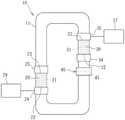
图1是示意性示出热声装置的示例的构造图;FIG. 1 is a configuration diagram schematically showing an example of a thermoacoustic device;
图2是隔膜结构的说明图;并且2 is an explanatory diagram of a diaphragm structure; and
图3是示出隔膜的逆压电效应的说明图。FIG. 3 is an explanatory diagram showing the inverse piezoelectric effect of the diaphragm.
具体实施方式Detailed ways
图1是示意性示出热声装置10的示例的构造图。本公开的热声装置10包括环管11,以及第一堆叠20和第二堆叠30,每一个堆叠都设置在环管11中。工作气体被密封在环管11中。工作气体是例如空气、氮气、氦气、氩气或它们至少两种的混合物。FIG. 1 is a configuration diagram schematically showing an example of a
第一堆叠20是柱状构件,并且具有在环管11的轴线方向上延伸穿过环管11的多个微流动路径21。第二堆叠30也是柱状构件,并且具有在环管11的轴线方向上延伸穿过环管11的多个微流动路径31。微流动路径21、31用作工作气体的通道。The
在轴向方向上,在第一堆叠20的第一端22和第二端23之间出现温度梯度。在本公开中,第一堆叠20的第一端22处的温度高于第一堆叠20的第二端23处的温度。当温度梯度超过临界点时,第一堆叠20中的工作气体振动。工作气体的振动产生声波。结果,在环管11中的工作气体中产生包括驻波的声波。由于声波,第二堆叠30的微流动路径31中的工作气体振动。然后,在第二堆叠30中出现温度梯度。在本公开中,出现温度梯度,其中第二堆叠30的第一端32处的温度高于第二堆叠30的第二端33处的温度。这样,第一堆叠20将热能转换成声能,而第二堆叠30将声能转换成热能。In the axial direction, a temperature gradient occurs between the
在本公开中,第一堆叠20和第二堆叠30具有相同的构造,但是可以具有不同的构造(例如,第一堆叠20和第二堆叠30可以在管轴线方向上具有不同的长度)。第一堆叠20和第二堆叠30由例如陶瓷制成,并且替代地可以由金属(例如不锈钢)制成。In the present disclosure, the
在第一堆叠20中,第一高温侧热交换器24设置在其中温度变高的第一端22上,第一低温侧热交换器25设置在其中温度变低的第二端23上。热交换器24、25执行环管11的外部与第一堆叠20之间的热交换。在第二堆叠30中,第二高温侧热交换器34设置在其中温度变高的第一端32上,第二低温侧热交换器35设置在其中温度变低的第二端33上。热交换器34、35执行环管11的外部与第二堆叠30之间的热交换。In the
第一高温侧热交换器24从外部热源29接收热(热能)。该热被传递到第一堆叠20的第一端22。这样,第一高温侧热交换器24从环管11的外部加热第一堆叠20的第一端22,并且将第一端22的温度升高到更高的温度(比第二端23更高的温度)。The first high temperature
第一低温侧热交换器25通过在环管11的外部与第一堆叠20的第二端23之间传导热来调整第二端23的温度。具体地,第一低温侧热交换器25具有调整第一堆叠20的第二端23的温度的功能,使得第二端23的温度不超过预定参考温度(第一参考温度)。第一参考温度是比第一堆叠20的第一端22的温度低的温度。The first low temperature
第一高温侧热交换器24和第一低温侧热交换器25控制第一堆叠20的第一端22与第二端23之间的温度梯度(温差)。第一低温侧热交换器25、第一堆叠20和第一高温侧热交换器24构成热声原动机(热声发动机),该热声原动机将热源29的热转换成环管11中的工作气体的振动以产生声波。The first high temperature
如上所述,声波由第一堆叠20中产生的温度梯度产生,并且温度梯度由产生的声波在第二堆叠30中产生。此时,第二堆叠30的第一端32的温度变得高于第二堆叠30的第二端33的温度。As described above, the acoustic waves are generated by the temperature gradient generated in the
第二高温侧热交换器34设置在第一端32上,在该第一端32中当温度梯度出现在第二堆叠30中时,温度变高。第二低温侧热交换器35设置在第二端33上,在该第二端33中当第二堆叠30中出现温度梯度时,温度变低。The second high temperature
第二高温侧热交换器34具有通过在环管11的外部与第二堆叠30的第一端32之间传导热来调整第一端32的温度的功能。例如,第二高温侧热交换器34保持第二堆叠30的第一端32的温度恒定(例如,保持在室温)。The second high temperature
第二低温侧热交换器35连接到设置在环管11外部的冷却目标37,使得热在第二低温侧热交换器35与冷却目标37之间传导。第二低温侧热交换器35吸收环管11外部的热(冷却目标37的热),并将该热传递到第二堆叠30的第二端33。因此,冷却目标37可以被冷却。换句话说,第二低温侧热交换器35取出具有低温的第二堆叠30的第二端33的冷热,并且由于在第二堆叠30中产生的温度梯度,将冷热传递到环管11(冷却目标37)外部。The second low temperature
第二低温侧热交换器35、第二堆叠30和第二高温侧热交换器34构成热声热泵,该热声热泵从声波(工作气体的振动)产生温度梯度。The second low temperature
图1中所示的热声装置10进一步包括隔膜结构40,该隔膜结构40包括设置在环管11中的隔膜39。隔膜39被构造成振动,以便不阻碍工作气体的振动。因此,隔膜39由膜状弹性体形成。在环管11中的由第一堆叠20的温度梯度产生的声波可以例如被隔膜39放大。The
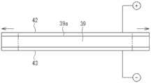
图2是隔膜结构40的说明图。隔膜结构40包括设置在环管11的一部分中的隔膜39和改变隔膜39刚度的操作单元41。本公开的隔膜39是具有逆压电效应的薄膜构件。更具体地,隔膜39是压电膜(聚合物压电膜)。当电压(电场)施加到隔膜39时,隔膜39可以根据电压(电场)的大小在沿着表面39a的方向上膨胀和收缩。隔膜39以对应于电压(电场)大小的变形量(膨胀量或收缩量)进行膨胀或收缩。FIG. 2 is an explanatory diagram of the
本公开的操作单元41包括电极42、43和电源44。为了在隔膜39的第一表面与隔膜39的第二表面之间产生电位差,第一电极42附接到隔膜39的第一表面,并且第二电极43附接到隔膜39的第二表面。电源44向电极42、43施加电压。The
例如,电极42、43可以设置在隔膜39的整个第一表面和整个第二表面上,并且替代地可以部分设置在隔膜39的周部39b上。注意,产生电场的范围和/或产生的电场的量根据电极42、43相对于隔膜39的面积(范围)而不同。在隔膜39中,受电场影响的区域膨胀和收缩。因此,随着电极42、43中的每一个电极的面积增大,膨胀和收缩的量增大,并且刚度的变化量增大。也就是说,当电极42、43设置在隔膜39的整个第一表面和整个第二表面上时,刚度的变化量增大。For example, the
利用上述构造,当电源44经由电极42、43向隔膜39施加电压时,隔膜39由于逆压电效应而变形。图3是示出隔膜39的逆压电效应的说明图。如图3中所示,当电压施加到隔膜39的两个表面时,隔膜39在沿着表面39a的方向上膨胀。With the above-described configuration, when the
如图2中所示,隔膜结构40包括一对环形约束构件47。约束构件47中的每一个约束构件具有与隔膜39的外周轮廓形状类似的外周轮廓形状。附接有电极42、43的隔膜39被夹在一对约束构件47之间,并且附接到设置在环管11上的凸缘部48。在本公开中,由于环管11和约束构件47由金属制成,因此将绝缘构件49插置在凸缘部48与约束构件47之间。绝缘构件49将电极42、43与环管11电绝缘。As shown in FIG. 2 , the
隔膜39的周部39b被约束构件47约束(即固定)到环管11。隔膜39的区域39c可以在管轴线方向上振动。区域39c比周部39b更靠近隔膜39的中心。在图2中,管轴线方向由箭头Y表示。隔膜39可以固定到约束构件47,使得当没有电压施加到隔膜39时,张力在沿着表面39a的方向上施加到隔膜39。The
隔膜39在其周部39b处被约束。因此,当隔膜39由于逆压电效应而在沿着表面39a的方向上膨胀(延伸)时,隔膜39的张力减小,并且隔膜39在管轴线方向(Y方向)上的刚度减小。因此,隔膜39能够以大振幅振动。相反,当隔膜39在沿着表面39a的方向上收缩(从其膨胀状态)时,隔膜39的张力增大,并且隔膜39在管轴线方向(Y方向)上的刚度增大。因此,隔膜39能够以小振幅振动。这样,隔膜39在管轴线方向上的表观刚度发生变化。The
在本公开中,电压被施加到隔膜39以改变隔膜39的刚度。也就是说,施加到隔膜39以改变刚度的物理量是电压。隔膜39和操作单元41中的每一个可以具有其他构造。例如,虽然未示出,但是操作单元41可以具有包括加热器和电源的构造,该加热器被构造成加热隔膜39,该电源被构造成向加热器供应电力。在这种情况下,施加到隔膜39的物理量是温度。隔膜39的温度由于加热器的热而改变,并且隔膜39的刚度由于热膨胀而改变。这样,操作单元41可以具有任何构造,只要操作单元41向隔膜39施加所需的物理量以改变隔膜39在管轴线方向上的刚度即可。In the present disclosure, a voltage is applied to the
隔膜结构40进一步包括控制器45。控制器45执行控制以改变施加到隔膜39的电压(物理量)。控制器45是计算机。换句话说,控制器45是包括处理器等的电子控制单元。控制器45向电源44输出控制信号。控制信号包括关于从电源44施加到隔膜39的电压大小的信息。也就是说,控制器45执行控制以改变从电源44施加到隔膜39的电压的大小。The
热声装置10进一步包括设置在环管11上的传感器46。传感器46被构造成检测与环管11中的工作气体的工作流量相关的参数。在本公开中,该参数表示环管11中工作气体的压力振幅。传感器46是压力传感器,其检测环管11中的工作气体的压力以检测压力振幅。传感器46检测工作气体的压力,并向控制器45输出检测信号。控制器45基于该检测信号检测工作流体(即,工作气体)的压力振幅的值(大小)。控制器45不断地检测压力振幅的值。基于检测结果,控制器45执行控制以改变隔膜39的刚度。The
该参数可以是例如堆叠30的温度或堆叠30周围的环境温度。在这种情况下,传感器46是温度传感器,并且优选地检测堆叠30在高温侧的一部分的温度或者堆叠30在高温侧的一部分的周围的温度。This parameter may be, for example, the temperature of the
将描述环管11中的工作气体的工作流量与工作气体的压力振幅(压力振幅量)之间的关系。工作流量与压力振幅之间存在相关性。当压力振幅大时,工作流量大,而当压力振幅小时,工作流量小。也就是说,当环管11中的工作气体的工作流量减小时,工作气体的压力振幅减小。可以认为压力振幅是环管11中的声音强度的大小。The relationship between the working flow rate of the working gas in the
将描述由控制器45执行的控制的具体示例。当环管11中的工作气体的工作流量减小时,工作气体的压力振幅减小。然后,控制器45减小隔膜39在管轴线方向上的刚度。为此,控制器45执行控制以与那时之前施加的电压相比减小施加到隔膜39的电压(物理量)。相反,当环管11中的工作气体的工作流量增大时,工作气体的压力振幅增大。然后,控制器45增大隔膜39在管轴线方向上的刚度。为此,控制器45执行控制以与那时之前施加的电压相比增大施加到隔膜39的电压(物理量)。上述控制称为“正常操作控制”。A specific example of the control performed by the
除了正常操作控制之外,由控制器45执行的控制包括下面描述的故障安全控制。在采集参数(在本公开中,工作气体的压力振幅)时,控制器45将参数值与预设阈值进行比较。该比较过程可以在每次采集参数时执行。当参数超过阈值时,控制器45将隔膜39的刚度增大到所需的刚度。所需的刚度是允许抑制环管11中的工作气体的振动的刚度(即,能够抑制环管11中的工作气体振动的刚度)。例如,隔膜39所需的刚度可以是可变范围内的最高刚度。当隔膜39的刚度变成所需的刚度时,环管11中工作气体的振动被隔膜39阻挡。In addition to the normal operational controls, the controls performed by the
根据故障安全控制,例如,可以停止热声装置10中的热声现象,而不停止热源29的操作,其中热源29是被构造成向堆叠20施加热的设备(见图1)。热源29例如是输出高温流体作为废热的热处理炉。由于热处理炉的废热,堆叠20的温度变高。在这种情况下,可以停止热声装置10的操作,而不停止热处理炉的操作。According to fail-safe controls, for example, thermoacoustic phenomena in
当工作气体的工作流量的循环在环管11中没有建立时(即,当工作气体的工作流量的循环在环管11中受到干扰时),即,当由于热源29引起的工作流量的增大与由于冷却目标37引起的工作流量的消耗之间的平衡可能丧失时,控制器45首先执行上述正常操作控制。也就是说,如果失去了上述平衡,控制器45增大隔膜39的刚度以减小工作气体的振幅量,或者减小隔膜39的刚度以增大工作气体的振幅量。因此,平衡被调整。在通过执行正常操作控制不能解决上述不平衡的情况下,控制器45可以执行故障安全控制。因此,工作流量被隔膜39停止。When the circulation of the working flow of the working gas is not established in the loop 11 (ie, when the circulation of the working flow of the working gas is disturbed in the loop 11 ), that is, when the increase of the working flow due to the
在上面的描述中,与工作气体的工作流量相关的参数是工作气体的压力振幅。然而,当与工作气体的工作流量相关的参数是堆叠30高温侧的一部分的温度或者堆叠30高温侧的一部分的周围的温度时,传感器46用作温度传感器。在这种情况下,如果传感器46的检测结果指示温度高于那时之前的温度(即,如果传感器46的检测结果指示温度升高),则控制器45执行控制以增大隔膜39的刚度。相反,如果传感器46的检测结果指示温度低于那时之前的该温度(即,如果传感器46的检测结果指示温度降低),则控制器45执行控制以减小隔膜39的刚度。In the above description, the parameter related to the working flow of the working gas is the pressure amplitude of the working gas. However, when the parameter related to the working flow of the working gas is the temperature of a part of the high temperature side of the
图2中所示的热声装置10进一步包括设置在环管11的管壁12上的振动发电单元50以及收获电源单元51。当环路管11中出现热声现象时,工作气体振动并产生声波,如上文所描述。因此,管壁12振动。包括压电元件的振动发电单元50附接到管壁12,并且压电元件由于管壁12的振动而变形。电能通过压电元件的压电效应从振动发电单元50输出。如上文所描述,振动发电单元50包括压电元件,并且振动发电单元50将管壁12的振动转换成电能。收获电源单元51基于由振动发电单元50获得的电能输出用于向隔膜39施加所需物理量(电压)的能量。在本公开中,收获电源单元51将电能作为电压输出,并将该电压施加到隔膜39。The
图2中所示的隔膜结构40包括开关52。开关52执行切换通电路径的操作,使得从常规电源44和收获电源单元51中选择用于向隔膜39施加电压的电源。该切换操作基于控制器45的控制信号来执行。例如,常规电源44用于在从热声装置10开始操作到工作气体产生振动的时段期间改变隔膜39的刚度,并且一旦在工作气体中发生振动,就使用收获电源单元51。通过提供收获电源单元51,可以用节省下来的能量操作热声装置10。The
虽然未示出,但是常规电源44和收获电源单元51中的一个可以省略。在隔膜39通过约束构件47附接到环管11的状态下,隔膜39的刚度被设定为预定的初始刚度。初始刚度是当在堆叠20中产生预定的温度差以启动热声装置10时允许环管11中的工作气体振动的刚度,而不是例如在上述故障安全控制中抑制振动的刚度。当工作流体(即,工作气体)的振动开始时,振动发电单元50将管壁12的振动转换成电能并输出电能。然后,基于电能,收获电源单元51向隔膜39供应电力,并且因此改变隔膜39的刚度。在这种情况下,常规电源44不是必需的。即,操作单元41的电源可以是收获电源单元51。Although not shown, one of the
如上所述,本公开的热声装置10包括:环管11,工作气体密封在该环管11中;堆叠20、30,该堆叠20、30设置在环管11中;以及隔膜结构40。环管11在管轴线方向上的温度梯度出现在堆叠20、30中。隔膜结构40包括设置在环管11中的隔膜39,以及操作单元41。隔膜39具有在与管轴线方向相交(垂直于管轴线方向)的方向上延伸的表面39a,并且隔膜39可以振动,并具有在管轴线方向上的分量(即,振动分量)。操作单元41向隔膜39施加所需的物理量,以改变隔膜39在管轴线方向上的刚度。本公开的物理量是电压。As described above, the
隔膜39的特性(刚度)影响环管11中工作气体的移动。在具有上述构造的热声装置10中,通过使用操作单元41向隔膜39施加电压来改变隔膜39的刚度(表观刚度),而不替换隔膜39。当隔膜39的刚度被设定为与工作气体的移动相匹配的刚度时,可以进一步提高由热声现象实现的工作效率。The properties (stiffness) of the
隔膜结构40包括控制器45,并且控制器45执行控制以改变施加到隔膜39的物理量(电压)。利用控制器45,隔膜39的刚度可以根据热声装置10的状态,即根据工作气体的移动而不同地改变。The
热声装置10包括传感器46,该传感器46被构造成检测与工作气体的工作流量相关的参数。在本公开中,参数是环管11中的工作气体的压力振幅。替代地,该参数可以是堆叠30的温度或堆叠30周围的环境温度。堆叠30的温度(或堆叠30周围的环境温度)和工作气体的压力振幅是影响工作气体的工作流量大小的参数。鉴于此,使用传感器46检测参数使得可以根据工作流量来调整隔膜39的刚度。因此,有可能进一步提高由热声现象实现的工作效率。The
隔膜39可以具有对应于工作气体状态的刚度。例如,具有在操作开始时的压力振幅的隔膜39的刚度可能不同于具有在稳定振动期间的压力振幅的隔膜39的刚度。当工作气体的填充压力(即,充气压力)增大以增大热声装置10的输出时,隔膜39的刚度可以根据填充压力而改变。这是通过本公开的热声装置10而实现的。隔膜39的刚度可以在工作气体振动期间改变。在相关技术中,为了改变隔膜的刚度,需要拆卸装置、替换隔膜并重新组装该装置。重新组装需要对例如隔膜的位置进行微调。然而,当本公开的热声装置10的隔膜39的刚度改变时,本公开的热声装置10不需要重新组装。因此,省略了相关技术中的微调。The
当参数由于环管11中工作气体的工作流量减少而改变时,控制器45减小隔膜39的刚度。相反,当参数由于工作流量的增大而改变时,控制器45增大隔膜39的刚度(正常操作控制)。在正常操作控制中,当工作气体的工作流量小时,热声装置10被调整,使得隔膜39的刚度减小,并且工作气体的振动不太可能被隔膜39抑制以增大工作流量。相反,当工作气体的工作流量大时,热声装置10被调整使得隔膜39的刚度增大,并且工作气体的振动被隔膜39减小,以减小工作流量。The
此外,如上所述,控制器45可以执行故障安全控制。也就是说,当参数超过阈值时,控制器45将隔膜39的刚度增大到允许工作气体的振动被抑制的刚度(即,能够抑制工作气体的振动的刚度)。通过这种控制,例如,可以停止热声装置10中的热声现象,而不停止热源29的操作,其中热源29向堆叠20施加热。Additionally, as described above, the
如上所述,在本公开的热声装置10中,可以改变隔膜39的刚度,而不替换隔膜39。这使得有可能进一步提高由热声现象实现的工作效率。As described above, in the
本公开中所公开的实施例是说明性的,但在所有方面都不是限制性的。本发明的范围不限于上述实施例,并且包括在等同于权利要求中描述的构造的范围内的任何和所有变型。例如,环管11的形状和堆叠20、30的布置等可以不同于附图中所示的那些。The embodiments disclosed in this disclosure are illustrative and not restrictive in all respects. The scope of the present invention is not limited to the above-described embodiments, and includes any and all modifications within a scope equivalent to the configuration described in the claims. For example, the shape of the
Claims (8)
Translated fromChineseApplications Claiming Priority (2)
| Application Number | Priority Date | Filing Date | Title |
|---|---|---|---|
| JP2019-089175 | 2019-05-09 | ||
| JP2019089175AJP7292631B2 (en) | 2019-05-09 | 2019-05-09 | thermoacoustic device |
Publications (1)
| Publication Number | Publication Date |
|---|---|
| CN111911378Atrue CN111911378A (en) | 2020-11-10 |
Family
ID=70482370
Family Applications (1)
| Application Number | Title | Priority Date | Filing Date |
|---|---|---|---|
| CN202010361847.8APendingCN111911378A (en) | 2019-05-09 | 2020-04-30 | Thermoacoustic device |
Country Status (4)
| Country | Link |
|---|---|
| US (1) | US11320176B2 (en) |
| EP (1) | EP3736510B1 (en) |
| JP (1) | JP7292631B2 (en) |
| CN (1) | CN111911378A (en) |
Families Citing this family (3)
| Publication number | Priority date | Publication date | Assignee | Title |
|---|---|---|---|---|
| JP7374534B1 (en) | 2023-01-06 | 2023-11-07 | 関東冶金工業株式会社 | Sonic generator, thermoacoustic engine and heat treatment furnace |
| JP7438581B1 (en) | 2023-01-06 | 2024-02-27 | 関東冶金工業株式会社 | Thermoacoustic engine and heat treatment furnace |
| WO2025074576A1 (en)* | 2023-10-05 | 2025-04-10 | 中央精機株式会社 | Thermoacoustic device and fluid supply method |
Citations (4)
| Publication number | Priority date | Publication date | Assignee | Title |
|---|---|---|---|---|
| US20040008853A1 (en)* | 1999-07-20 | 2004-01-15 | Sri International, A California Corporation | Electroactive polymer devices for moving fluid |
| CN1916403A (en)* | 2006-09-05 | 2007-02-21 | 浙江大学 | Air-cooled thermoacoustic engine |
| US7908856B2 (en)* | 2007-10-24 | 2011-03-22 | Los Alamos National Security, Llc | In-line stirling energy system |
| JP2011153742A (en)* | 2010-01-26 | 2011-08-11 | Isuzu Motors Ltd | Thermoacoustic engine |
Family Cites Families (12)
| Publication number | Priority date | Publication date | Assignee | Title |
|---|---|---|---|---|
| US7081699B2 (en)* | 2003-03-31 | 2006-07-25 | The Penn State Research Foundation | Thermoacoustic piezoelectric generator |
| JP2004340506A (en)* | 2003-05-16 | 2004-12-02 | Matsushita Electric Ind Co Ltd | refrigerator |
| JP2005188401A (en) | 2003-12-25 | 2005-07-14 | Toyota Motor Corp | Thermoacoustic energy generator |
| JP2005351224A (en)* | 2004-06-11 | 2005-12-22 | Toyota Motor Corp | Thermoacoustic engine |
| JP4652822B2 (en)* | 2005-01-07 | 2011-03-16 | 学校法人同志社 | Thermoacoustic device |
| JP2009216045A (en)* | 2008-03-12 | 2009-09-24 | Mazda Motor Corp | Exhaust device of engine |
| JP2011231940A (en)* | 2010-04-23 | 2011-11-17 | Honda Motor Co Ltd | Thermoacoustic engine |
| US8375729B2 (en)* | 2010-04-30 | 2013-02-19 | Palo Alto Research Center Incorporated | Optimization of a thermoacoustic apparatus based on operating conditions and selected user input |
| JP5862250B2 (en) | 2011-12-01 | 2016-02-16 | いすゞ自動車株式会社 | Thermoacoustic refrigeration equipment |
| JP2018042415A (en)* | 2016-09-09 | 2018-03-15 | 株式会社東芝 | Power generation unit and instrumentation unit |
| JP6781899B2 (en) | 2016-10-18 | 2020-11-11 | 株式会社ジェイテクト | Thermoacoustic device |
| JP6724755B2 (en) | 2016-12-06 | 2020-07-15 | 株式会社Soken | Thermoacoustic device |
- 2019
- 2019-05-09JPJP2019089175Apatent/JP7292631B2/enactiveActive
- 2020
- 2020-04-28USUS16/860,838patent/US11320176B2/enactiveActive
- 2020-04-30EPEP20172387.1Apatent/EP3736510B1/enactiveActive
- 2020-04-30CNCN202010361847.8Apatent/CN111911378A/enactivePending
Patent Citations (4)
| Publication number | Priority date | Publication date | Assignee | Title |
|---|---|---|---|---|
| US20040008853A1 (en)* | 1999-07-20 | 2004-01-15 | Sri International, A California Corporation | Electroactive polymer devices for moving fluid |
| CN1916403A (en)* | 2006-09-05 | 2007-02-21 | 浙江大学 | Air-cooled thermoacoustic engine |
| US7908856B2 (en)* | 2007-10-24 | 2011-03-22 | Los Alamos National Security, Llc | In-line stirling energy system |
| JP2011153742A (en)* | 2010-01-26 | 2011-08-11 | Isuzu Motors Ltd | Thermoacoustic engine |
Also Published As
| Publication number | Publication date |
|---|---|
| EP3736510A1 (en) | 2020-11-11 |
| US11320176B2 (en) | 2022-05-03 |
| JP2020183849A (en) | 2020-11-12 |
| EP3736510B1 (en) | 2023-03-08 |
| JP7292631B2 (en) | 2023-06-19 |
| US20200355408A1 (en) | 2020-11-12 |
Similar Documents
| Publication | Publication Date | Title |
|---|---|---|
| CN111911378A (en) | Thermoacoustic device | |
| AU2013286714B2 (en) | Systems and methods for regulating the resonant frequency of a disc pump cavity | |
| US11306711B2 (en) | Miniature cooling system | |
| AU2011212955B2 (en) | Fluid disc pump square-wave driver | |
| RU2511832C2 (en) | Pump with disk-shaped cavity | |
| AU2013230494B2 (en) | Disc pump with advanced actuator | |
| EP2812575A2 (en) | Systems and methods for regulating the temperature of a disc pump system | |
| KR20110121593A (en) | Optimization of thermoacoustic devices based on operating conditions and selected user input | |
| CN101354045A (en) | Piezoelectric fan, method of cooling microelectronic device using same, and system incorporating same | |
| EP2898217A1 (en) | Thermoacoustic transducer apparatus including a transmission duct | |
| JP2022537376A (en) | Piezoelectric actuators and microfluidic devices | |
| AU2013216967A1 (en) | Systems and methods for monitoring reduced pressure supplied by a disc pump system | |
| CN110168291A (en) | Thermoacoustic devices | |
| Prasad et al. | Two-port electroacoustic model of a piezoelectric circular composite plate | |
| CN109845293A (en) | Vibrate carrier, ultrasonic transducer tectosome and Medical Devices | |
| JP2011114597A (en) | Piezoelectric actuator and electronic apparatus | |
| CN114719116A (en) | A Piezoelectric Ceramic-Based Pipeline Pressure Pulsation Vibration Damping Device and Control System | |
| WO2019093050A1 (en) | Refrigeration machine | |
| JP4396220B2 (en) | Variable damping device | |
| Giannuzzi et al. | Limitations on Piezoelectric-Based Valve Actuators | |
| Keoschkerjan et al. | Analysis of self-heating phenomenon of piezoelectric microcomponents actuated harmonically | |
| JP2007150523A (en) | Speaker | |
| JP4951324B2 (en) | Piezoelectric vibrator | |
| Farsangi et al. | A Tunable Helmholtz Resonator for Electromagnetic Energy Harvesting | |
| JP2002233175A (en) | Actuator and driving method thereof |
Legal Events
| Date | Code | Title | Description |
|---|---|---|---|
| PB01 | Publication | ||
| PB01 | Publication | ||
| SE01 | Entry into force of request for substantive examination | ||
| SE01 | Entry into force of request for substantive examination | ||
| CB02 | Change of applicant information | Address after:Aichi Prefecture, Japan Applicant after:JTEKT Corp. Applicant after:Public University Legal Person Osaka Address before:Osaka, Japan Applicant before:JTEKT Corp. Applicant before:Public University Legal Person Osaka | |
| CB02 | Change of applicant information | ||
| WD01 | Invention patent application deemed withdrawn after publication | Application publication date:20201110 | |
| WD01 | Invention patent application deemed withdrawn after publication |