CN111905231A - Conduit device including valve for controlling fluid flow through conduit - Google Patents
Conduit device including valve for controlling fluid flow through conduitDownload PDFInfo
- Publication number
- CN111905231A CN111905231ACN202010855332.3ACN202010855332ACN111905231ACN 111905231 ACN111905231 ACN 111905231ACN 202010855332 ACN202010855332 ACN 202010855332ACN 111905231 ACN111905231 ACN 111905231A
- Authority
- CN
- China
- Prior art keywords
- valve
- catheter device
- catheter
- feed
- control space
- Prior art date
- Legal status (The legal status is an assumption and is not a legal conclusion. Google has not performed a legal analysis and makes no representation as to the accuracy of the status listed.)
- Granted
Links
Images


Classifications
- A—HUMAN NECESSITIES
- A61—MEDICAL OR VETERINARY SCIENCE; HYGIENE
- A61M—DEVICES FOR INTRODUCING MEDIA INTO, OR ONTO, THE BODY; DEVICES FOR TRANSDUCING BODY MEDIA OR FOR TAKING MEDIA FROM THE BODY; DEVICES FOR PRODUCING OR ENDING SLEEP OR STUPOR
- A61M60/00—Blood pumps; Devices for mechanical circulatory actuation; Balloon pumps for circulatory assistance
- A61M60/80—Constructional details other than related to driving
- A61M60/802—Constructional details other than related to driving of non-positive displacement blood pumps
- A61M60/818—Bearings
- A61M60/82—Magnetic bearings
- A—HUMAN NECESSITIES
- A61—MEDICAL OR VETERINARY SCIENCE; HYGIENE
- A61M—DEVICES FOR INTRODUCING MEDIA INTO, OR ONTO, THE BODY; DEVICES FOR TRANSDUCING BODY MEDIA OR FOR TAKING MEDIA FROM THE BODY; DEVICES FOR PRODUCING OR ENDING SLEEP OR STUPOR
- A61M39/00—Tubes, tube connectors, tube couplings, valves, access sites or the like, specially adapted for medical use
- A61M39/22—Valves or arrangement of valves
- A—HUMAN NECESSITIES
- A61—MEDICAL OR VETERINARY SCIENCE; HYGIENE
- A61M—DEVICES FOR INTRODUCING MEDIA INTO, OR ONTO, THE BODY; DEVICES FOR TRANSDUCING BODY MEDIA OR FOR TAKING MEDIA FROM THE BODY; DEVICES FOR PRODUCING OR ENDING SLEEP OR STUPOR
- A61M25/00—Catheters; Hollow probes
- A61M25/0021—Catheters; Hollow probes characterised by the form of the tubing
- A61M25/0023—Catheters; Hollow probes characterised by the form of the tubing by the form of the lumen, e.g. cross-section, variable diameter
- A61M25/0026—Multi-lumen catheters with stationary elements
- A61M25/003—Multi-lumen catheters with stationary elements characterized by features relating to least one lumen located at the distal part of the catheter, e.g. filters, plugs or valves
- A—HUMAN NECESSITIES
- A61—MEDICAL OR VETERINARY SCIENCE; HYGIENE
- A61M—DEVICES FOR INTRODUCING MEDIA INTO, OR ONTO, THE BODY; DEVICES FOR TRANSDUCING BODY MEDIA OR FOR TAKING MEDIA FROM THE BODY; DEVICES FOR PRODUCING OR ENDING SLEEP OR STUPOR
- A61M39/00—Tubes, tube connectors, tube couplings, valves, access sites or the like, specially adapted for medical use
- A61M39/22—Valves or arrangement of valves
- A61M39/223—Multiway valves
- A—HUMAN NECESSITIES
- A61—MEDICAL OR VETERINARY SCIENCE; HYGIENE
- A61M—DEVICES FOR INTRODUCING MEDIA INTO, OR ONTO, THE BODY; DEVICES FOR TRANSDUCING BODY MEDIA OR FOR TAKING MEDIA FROM THE BODY; DEVICES FOR PRODUCING OR ENDING SLEEP OR STUPOR
- A61M60/00—Blood pumps; Devices for mechanical circulatory actuation; Balloon pumps for circulatory assistance
- A61M60/10—Location thereof with respect to the patient's body
- A61M60/122—Implantable pumps or pumping devices, i.e. the blood being pumped inside the patient's body
- A61M60/126—Implantable pumps or pumping devices, i.e. the blood being pumped inside the patient's body implantable via, into, inside, in line, branching on, or around a blood vessel
- A61M60/13—Implantable pumps or pumping devices, i.e. the blood being pumped inside the patient's body implantable via, into, inside, in line, branching on, or around a blood vessel by means of a catheter allowing explantation, e.g. catheter pumps temporarily introduced via the vascular system
- A—HUMAN NECESSITIES
- A61—MEDICAL OR VETERINARY SCIENCE; HYGIENE
- A61M—DEVICES FOR INTRODUCING MEDIA INTO, OR ONTO, THE BODY; DEVICES FOR TRANSDUCING BODY MEDIA OR FOR TAKING MEDIA FROM THE BODY; DEVICES FOR PRODUCING OR ENDING SLEEP OR STUPOR
- A61M60/00—Blood pumps; Devices for mechanical circulatory actuation; Balloon pumps for circulatory assistance
- A61M60/20—Type thereof
- A61M60/205—Non-positive displacement blood pumps
- A61M60/216—Non-positive displacement blood pumps including a rotating member acting on the blood, e.g. impeller
- A—HUMAN NECESSITIES
- A61—MEDICAL OR VETERINARY SCIENCE; HYGIENE
- A61M—DEVICES FOR INTRODUCING MEDIA INTO, OR ONTO, THE BODY; DEVICES FOR TRANSDUCING BODY MEDIA OR FOR TAKING MEDIA FROM THE BODY; DEVICES FOR PRODUCING OR ENDING SLEEP OR STUPOR
- A61M60/00—Blood pumps; Devices for mechanical circulatory actuation; Balloon pumps for circulatory assistance
- A61M60/40—Details relating to driving
- A61M60/403—Details relating to driving for non-positive displacement blood pumps
- A61M60/408—Details relating to driving for non-positive displacement blood pumps the force acting on the blood contacting member being mechanical, e.g. transmitted by a shaft or cable
- A61M60/411—Details relating to driving for non-positive displacement blood pumps the force acting on the blood contacting member being mechanical, e.g. transmitted by a shaft or cable generated by an electromotor
- A61M60/414—Details relating to driving for non-positive displacement blood pumps the force acting on the blood contacting member being mechanical, e.g. transmitted by a shaft or cable generated by an electromotor transmitted by a rotating cable, e.g. for blood pumps mounted on a catheter
- B—PERFORMING OPERATIONS; TRANSPORTING
- B03—SEPARATION OF SOLID MATERIALS USING LIQUIDS OR USING PNEUMATIC TABLES OR JIGS; MAGNETIC OR ELECTROSTATIC SEPARATION OF SOLID MATERIALS FROM SOLID MATERIALS OR FLUIDS; SEPARATION BY HIGH-VOLTAGE ELECTRIC FIELDS
- B03C—MAGNETIC OR ELECTROSTATIC SEPARATION OF SOLID MATERIALS FROM SOLID MATERIALS OR FLUIDS; SEPARATION BY HIGH-VOLTAGE ELECTRIC FIELDS
- B03C1/00—Magnetic separation
- B03C1/02—Magnetic separation acting directly on the substance being separated
- B03C1/025—High gradient magnetic separators
- B03C1/031—Component parts; Auxiliary operations
- B03C1/033—Component parts; Auxiliary operations characterised by the magnetic circuit
- B03C1/0332—Component parts; Auxiliary operations characterised by the magnetic circuit using permanent magnets
- B—PERFORMING OPERATIONS; TRANSPORTING
- B03—SEPARATION OF SOLID MATERIALS USING LIQUIDS OR USING PNEUMATIC TABLES OR JIGS; MAGNETIC OR ELECTROSTATIC SEPARATION OF SOLID MATERIALS FROM SOLID MATERIALS OR FLUIDS; SEPARATION BY HIGH-VOLTAGE ELECTRIC FIELDS
- B03C—MAGNETIC OR ELECTROSTATIC SEPARATION OF SOLID MATERIALS FROM SOLID MATERIALS OR FLUIDS; SEPARATION BY HIGH-VOLTAGE ELECTRIC FIELDS
- B03C1/00—Magnetic separation
- B03C1/02—Magnetic separation acting directly on the substance being separated
- B03C1/10—Magnetic separation acting directly on the substance being separated with cylindrical material carriers
- B03C1/14—Magnetic separation acting directly on the substance being separated with cylindrical material carriers with non-movable magnets
- B—PERFORMING OPERATIONS; TRANSPORTING
- B03—SEPARATION OF SOLID MATERIALS USING LIQUIDS OR USING PNEUMATIC TABLES OR JIGS; MAGNETIC OR ELECTROSTATIC SEPARATION OF SOLID MATERIALS FROM SOLID MATERIALS OR FLUIDS; SEPARATION BY HIGH-VOLTAGE ELECTRIC FIELDS
- B03C—MAGNETIC OR ELECTROSTATIC SEPARATION OF SOLID MATERIALS FROM SOLID MATERIALS OR FLUIDS; SEPARATION BY HIGH-VOLTAGE ELECTRIC FIELDS
- B03C1/00—Magnetic separation
- B03C1/02—Magnetic separation acting directly on the substance being separated
- B03C1/28—Magnetic plugs and dipsticks
- B03C1/288—Magnetic plugs and dipsticks disposed at the outer circumference of a recipient
- B—PERFORMING OPERATIONS; TRANSPORTING
- B03—SEPARATION OF SOLID MATERIALS USING LIQUIDS OR USING PNEUMATIC TABLES OR JIGS; MAGNETIC OR ELECTROSTATIC SEPARATION OF SOLID MATERIALS FROM SOLID MATERIALS OR FLUIDS; SEPARATION BY HIGH-VOLTAGE ELECTRIC FIELDS
- B03C—MAGNETIC OR ELECTROSTATIC SEPARATION OF SOLID MATERIALS FROM SOLID MATERIALS OR FLUIDS; SEPARATION BY HIGH-VOLTAGE ELECTRIC FIELDS
- B03C1/00—Magnetic separation
- B03C1/02—Magnetic separation acting directly on the substance being separated
- B03C1/30—Combinations with other devices, not otherwise provided for
- A—HUMAN NECESSITIES
- A61—MEDICAL OR VETERINARY SCIENCE; HYGIENE
- A61M—DEVICES FOR INTRODUCING MEDIA INTO, OR ONTO, THE BODY; DEVICES FOR TRANSDUCING BODY MEDIA OR FOR TAKING MEDIA FROM THE BODY; DEVICES FOR PRODUCING OR ENDING SLEEP OR STUPOR
- A61M39/00—Tubes, tube connectors, tube couplings, valves, access sites or the like, specially adapted for medical use
- A61M39/22—Valves or arrangement of valves
- A61M39/223—Multiway valves
- A61M2039/224—Multiway valves of the slide-valve type
- A—HUMAN NECESSITIES
- A61—MEDICAL OR VETERINARY SCIENCE; HYGIENE
- A61M—DEVICES FOR INTRODUCING MEDIA INTO, OR ONTO, THE BODY; DEVICES FOR TRANSDUCING BODY MEDIA OR FOR TAKING MEDIA FROM THE BODY; DEVICES FOR PRODUCING OR ENDING SLEEP OR STUPOR
- A61M39/00—Tubes, tube connectors, tube couplings, valves, access sites or the like, specially adapted for medical use
- A61M39/22—Valves or arrangement of valves
- A61M2039/226—Spindles or actuating means
- A—HUMAN NECESSITIES
- A61—MEDICAL OR VETERINARY SCIENCE; HYGIENE
- A61M—DEVICES FOR INTRODUCING MEDIA INTO, OR ONTO, THE BODY; DEVICES FOR TRANSDUCING BODY MEDIA OR FOR TAKING MEDIA FROM THE BODY; DEVICES FOR PRODUCING OR ENDING SLEEP OR STUPOR
- A61M2205/00—General characteristics of the apparatus
- A61M2205/02—General characteristics of the apparatus characterised by a particular materials
- A61M2205/0272—Electro-active or magneto-active materials
- A—HUMAN NECESSITIES
- A61—MEDICAL OR VETERINARY SCIENCE; HYGIENE
- A61M—DEVICES FOR INTRODUCING MEDIA INTO, OR ONTO, THE BODY; DEVICES FOR TRANSDUCING BODY MEDIA OR FOR TAKING MEDIA FROM THE BODY; DEVICES FOR PRODUCING OR ENDING SLEEP OR STUPOR
- A61M2205/00—General characteristics of the apparatus
- A61M2205/75—General characteristics of the apparatus with filters
- A61M2205/7545—General characteristics of the apparatus with filters for solid matter, e.g. microaggregates
- A—HUMAN NECESSITIES
- A61—MEDICAL OR VETERINARY SCIENCE; HYGIENE
- A61M—DEVICES FOR INTRODUCING MEDIA INTO, OR ONTO, THE BODY; DEVICES FOR TRANSDUCING BODY MEDIA OR FOR TAKING MEDIA FROM THE BODY; DEVICES FOR PRODUCING OR ENDING SLEEP OR STUPOR
- A61M25/00—Catheters; Hollow probes
- A61M25/0043—Catheters; Hollow probes characterised by structural features
- A—HUMAN NECESSITIES
- A61—MEDICAL OR VETERINARY SCIENCE; HYGIENE
- A61M—DEVICES FOR INTRODUCING MEDIA INTO, OR ONTO, THE BODY; DEVICES FOR TRANSDUCING BODY MEDIA OR FOR TAKING MEDIA FROM THE BODY; DEVICES FOR PRODUCING OR ENDING SLEEP OR STUPOR
- A61M25/00—Catheters; Hollow probes
- A61M25/01—Introducing, guiding, advancing, emplacing or holding catheters
- A61M25/06—Body-piercing guide needles or the like
- A61M25/0606—"Over-the-needle" catheter assemblies, e.g. I.V. catheters
- A—HUMAN NECESSITIES
- A61—MEDICAL OR VETERINARY SCIENCE; HYGIENE
- A61M—DEVICES FOR INTRODUCING MEDIA INTO, OR ONTO, THE BODY; DEVICES FOR TRANSDUCING BODY MEDIA OR FOR TAKING MEDIA FROM THE BODY; DEVICES FOR PRODUCING OR ENDING SLEEP OR STUPOR
- A61M25/00—Catheters; Hollow probes
- A61M25/10—Balloon catheters
- A61M25/1018—Balloon inflating or inflation-control devices
- A61M25/10184—Means for controlling or monitoring inflation or deflation
- A61M25/10185—Valves
- A—HUMAN NECESSITIES
- A61—MEDICAL OR VETERINARY SCIENCE; HYGIENE
- A61M—DEVICES FOR INTRODUCING MEDIA INTO, OR ONTO, THE BODY; DEVICES FOR TRANSDUCING BODY MEDIA OR FOR TAKING MEDIA FROM THE BODY; DEVICES FOR PRODUCING OR ENDING SLEEP OR STUPOR
- A61M60/00—Blood pumps; Devices for mechanical circulatory actuation; Balloon pumps for circulatory assistance
- A61M60/10—Location thereof with respect to the patient's body
- A61M60/122—Implantable pumps or pumping devices, i.e. the blood being pumped inside the patient's body
- A61M60/126—Implantable pumps or pumping devices, i.e. the blood being pumped inside the patient's body implantable via, into, inside, in line, branching on, or around a blood vessel
- A61M60/148—Implantable pumps or pumping devices, i.e. the blood being pumped inside the patient's body implantable via, into, inside, in line, branching on, or around a blood vessel in line with a blood vessel using resection or like techniques, e.g. permanent endovascular heart assist devices
- A—HUMAN NECESSITIES
- A61—MEDICAL OR VETERINARY SCIENCE; HYGIENE
- A61M—DEVICES FOR INTRODUCING MEDIA INTO, OR ONTO, THE BODY; DEVICES FOR TRANSDUCING BODY MEDIA OR FOR TAKING MEDIA FROM THE BODY; DEVICES FOR PRODUCING OR ENDING SLEEP OR STUPOR
- A61M60/00—Blood pumps; Devices for mechanical circulatory actuation; Balloon pumps for circulatory assistance
- A61M60/20—Type thereof
- A61M60/247—Positive displacement blood pumps
- A61M60/253—Positive displacement blood pumps including a displacement member directly acting on the blood
- A61M60/268—Positive displacement blood pumps including a displacement member directly acting on the blood the displacement member being flexible, e.g. membranes, diaphragms or bladders
- A61M60/279—Peristaltic pumps, e.g. roller pumps
- A—HUMAN NECESSITIES
- A61—MEDICAL OR VETERINARY SCIENCE; HYGIENE
- A61M—DEVICES FOR INTRODUCING MEDIA INTO, OR ONTO, THE BODY; DEVICES FOR TRANSDUCING BODY MEDIA OR FOR TAKING MEDIA FROM THE BODY; DEVICES FOR PRODUCING OR ENDING SLEEP OR STUPOR
- A61M60/00—Blood pumps; Devices for mechanical circulatory actuation; Balloon pumps for circulatory assistance
- A61M60/40—Details relating to driving
- A61M60/424—Details relating to driving for positive displacement blood pumps
- A61M60/438—Details relating to driving for positive displacement blood pumps the force acting on the blood contacting member being mechanical
- A—HUMAN NECESSITIES
- A61—MEDICAL OR VETERINARY SCIENCE; HYGIENE
- A61M—DEVICES FOR INTRODUCING MEDIA INTO, OR ONTO, THE BODY; DEVICES FOR TRANSDUCING BODY MEDIA OR FOR TAKING MEDIA FROM THE BODY; DEVICES FOR PRODUCING OR ENDING SLEEP OR STUPOR
- A61M60/00—Blood pumps; Devices for mechanical circulatory actuation; Balloon pumps for circulatory assistance
- A61M60/50—Details relating to control
- A61M60/508—Electronic control means, e.g. for feedback regulation
- A61M60/515—Regulation using real-time patient data
- A61M60/523—Regulation using real-time patient data using blood flow data, e.g. from blood flow transducers
- A—HUMAN NECESSITIES
- A61—MEDICAL OR VETERINARY SCIENCE; HYGIENE
- A61M—DEVICES FOR INTRODUCING MEDIA INTO, OR ONTO, THE BODY; DEVICES FOR TRANSDUCING BODY MEDIA OR FOR TAKING MEDIA FROM THE BODY; DEVICES FOR PRODUCING OR ENDING SLEEP OR STUPOR
- A61M60/00—Blood pumps; Devices for mechanical circulatory actuation; Balloon pumps for circulatory assistance
- A61M60/50—Details relating to control
- A61M60/508—Electronic control means, e.g. for feedback regulation
- A61M60/538—Regulation using real-time blood pump operational parameter data, e.g. motor current
- A61M60/546—Regulation using real-time blood pump operational parameter data, e.g. motor current of blood flow, e.g. by adapting rotor speed
- A—HUMAN NECESSITIES
- A61—MEDICAL OR VETERINARY SCIENCE; HYGIENE
- A61M—DEVICES FOR INTRODUCING MEDIA INTO, OR ONTO, THE BODY; DEVICES FOR TRANSDUCING BODY MEDIA OR FOR TAKING MEDIA FROM THE BODY; DEVICES FOR PRODUCING OR ENDING SLEEP OR STUPOR
- A61M60/00—Blood pumps; Devices for mechanical circulatory actuation; Balloon pumps for circulatory assistance
- A61M60/80—Constructional details other than related to driving
- A61M60/802—Constructional details other than related to driving of non-positive displacement blood pumps
- A61M60/827—Sealings between moving parts
- A61M60/829—Sealings between moving parts having a purge fluid supply
- A—HUMAN NECESSITIES
- A61—MEDICAL OR VETERINARY SCIENCE; HYGIENE
- A61M—DEVICES FOR INTRODUCING MEDIA INTO, OR ONTO, THE BODY; DEVICES FOR TRANSDUCING BODY MEDIA OR FOR TAKING MEDIA FROM THE BODY; DEVICES FOR PRODUCING OR ENDING SLEEP OR STUPOR
- A61M60/00—Blood pumps; Devices for mechanical circulatory actuation; Balloon pumps for circulatory assistance
- A61M60/80—Constructional details other than related to driving
- A61M60/855—Constructional details other than related to driving of implantable pumps or pumping devices
- A61M60/89—Valves
- A61M60/892—Active valves, i.e. actuated by an external force
- B—PERFORMING OPERATIONS; TRANSPORTING
- B03—SEPARATION OF SOLID MATERIALS USING LIQUIDS OR USING PNEUMATIC TABLES OR JIGS; MAGNETIC OR ELECTROSTATIC SEPARATION OF SOLID MATERIALS FROM SOLID MATERIALS OR FLUIDS; SEPARATION BY HIGH-VOLTAGE ELECTRIC FIELDS
- B03C—MAGNETIC OR ELECTROSTATIC SEPARATION OF SOLID MATERIALS FROM SOLID MATERIALS OR FLUIDS; SEPARATION BY HIGH-VOLTAGE ELECTRIC FIELDS
- B03C2201/00—Details of magnetic or electrostatic separation
- B03C2201/18—Magnetic separation whereby the particles are suspended in a liquid
- B—PERFORMING OPERATIONS; TRANSPORTING
- B03—SEPARATION OF SOLID MATERIALS USING LIQUIDS OR USING PNEUMATIC TABLES OR JIGS; MAGNETIC OR ELECTROSTATIC SEPARATION OF SOLID MATERIALS FROM SOLID MATERIALS OR FLUIDS; SEPARATION BY HIGH-VOLTAGE ELECTRIC FIELDS
- B03C—MAGNETIC OR ELECTROSTATIC SEPARATION OF SOLID MATERIALS FROM SOLID MATERIALS OR FLUIDS; SEPARATION BY HIGH-VOLTAGE ELECTRIC FIELDS
- B03C2201/00—Details of magnetic or electrostatic separation
- B03C2201/26—Details of magnetic or electrostatic separation for use in medical or biological applications
Landscapes
- Health & Medical Sciences (AREA)
- Heart & Thoracic Surgery (AREA)
- Engineering & Computer Science (AREA)
- Life Sciences & Earth Sciences (AREA)
- Public Health (AREA)
- Hematology (AREA)
- Anesthesiology (AREA)
- Animal Behavior & Ethology (AREA)
- General Health & Medical Sciences (AREA)
- Biomedical Technology (AREA)
- Veterinary Medicine (AREA)
- Cardiology (AREA)
- Mechanical Engineering (AREA)
- Pulmonology (AREA)
- Vascular Medicine (AREA)
- Biophysics (AREA)
- Medical Informatics (AREA)
- Infusion, Injection, And Reservoir Apparatuses (AREA)
- External Artificial Organs (AREA)
- Media Introduction/Drainage Providing Device (AREA)
- Transplantation (AREA)
Abstract
Translated fromChinese
Description
Translated fromChinese本申请是于2017年7月24日递交的申请号为201680006875.X、发明名称为“包括用于控制通过导管的流体流的阀的导管装置”的分案申请This application is a divisional application filed on July 24, 2017 with application number 201680006875.X and titled "Conduit device including a valve for controlling fluid flow through a conduit"
技术领域technical field
本发明属于机械领域并尤其有利地可应用于医疗技术领域。本发明尤其涉及一种阀,即使在不同的压力条件下也允许可靠地阻塞通过导管的流体流。The invention belongs to the field of mechanics and is particularly advantageously applicable to the field of medical technology. In particular, the present invention relates to a valve that allows reliable blocking of fluid flow through a conduit, even under different pressure conditions.
背景技术Background technique
根据现有技术已知用于控制流体流的各种截止阀。例如DE 20 2013 104711 A1中公开了一种工业开发成熟的一次性的截止阀。例如根据DE 11 2009 003 676 T5已知一种简单的止回阀。这种止回阀应用于例如机动车辆技术中。这种截止阀基本上具有非常有限的应用范围,其中问题出现在过压或欠压或压力波动的情况下,因为这些阀通常仅设计用于窄压力范围。然而,介质的分离更加是绝对必需的,也就是说,例如在医疗领域的应用,也在其他特殊领域的应用中,包括阻塞位置的实际流体通道必须与阀的其它元件(例如驱动元件)气密地封闭。Various shut-off valves for controlling fluid flow are known from the prior art. For example, DE 20 2013 104711 A1 discloses an industrially developed disposable shut-off valve. A simple check valve is known, for example, from DE 11 2009 003 676 T5. Such non-return valves are used, for example, in motor vehicle technology. Such shut-off valves basically have a very limited range of applications, where problems arise in the case of over- or under-pressure or pressure fluctuations, since these valves are generally only designed for narrow pressure ranges. However, the separation of the medium is more absolutely necessary, that is to say, for example in applications in the medical field, but also in other special fields, the actual fluid passage including the blocking position must be in air with the other elements of the valve (eg drive elements) tightly closed.
此外,简单的清洁和灭菌可能性或在使用一次性部件的情况下选择性地简单的可更换性对于医疗技术领域中的应用是重要的。Furthermore, simple cleaning and sterilization possibilities or optionally simple exchangeability when using disposable components are important for applications in the field of medical technology.
发明内容SUMMARY OF THE INVENTION
在现有技术的背景下,因此本发明的目的是创建一种导管装置或一种阀,其允许在低流体吞吐量下,也可在不同的压力条件下可靠地关闭和打开流体通道。In the context of the state of the art, the object of the present invention is therefore to create a catheter device or a valve that allows reliable closing and opening of fluid passages under low fluid throughput, also under different pressure conditions.
该目的通过本发明的特征来实现。在下文中指出了本发明的有利实施例。This object is achieved by the features of the present invention. In the following, advantageous embodiments of the invention are pointed out.
这首先涉及导管装置,其包括用于引入生物体的导管,以及具有导管装置的一部分的用于引导流体流的至少一个内腔,还包括具有阀控制空间的用于控制特别是通过导管的流体流的阀,其中进料通道从进料口伸出,并且排出通道从排出口伸出,并且具有封闭元件,该封闭元件以可控制的方式在阀控制空间中可移动并且在至少一个第一位置关闭排出口,在至少一个第二位置关闭进料口,并且在至少一个第三位置中保持进料口和排出口之间的连接通道打开,其中提供有阀驱动器,其选择性地移动封闭元件至少进入第一、第二或第三位置中,其中所述至少一个内腔以流体传导方式连接到进料通道或者连接到排出通道。This first concerns a catheter device comprising a catheter for introduction into a living body, and at least one lumen having a portion of the catheter device for directing the flow of fluid, and also including a valve control space for controlling the fluid especially through the catheter A valve for flow, wherein the feed channel projects from the feed port and the discharge channel projects from the discharge port and has a closure element which is controllably movable in the valve control space and in at least one first position closes the discharge port, closes the feed port in at least one second position, and maintains the connecting passage between the feed port and the discharge port open in at least one third position, wherein a valve actuator is provided which selectively moves the closure The element enters at least the first, second or third position, wherein the at least one lumen is fluidically connected to the feed channel or to the exhaust channel.
下面再次进一步详细说明,使用导管装置可以非常精确地引导冲洗液,这是关于冲洗方向以及关于导管中的冲洗量和冲洗流的情况。这尤其是在柔性可旋转轴的背景下进行,取决于装置的长度和位置,其尤其具有抽吸效果或变化的压力条件。此外,阀的完美功能在医疗技术领域确实是至关重要的。特别地,与分离装置的耦合也是可控的,所述分离装置用于从冲洗液中除去污染和磨损碎片(例如金属磨损碎屑)。例如,如果用于清洁的临时方向反转在分离装置(因而用于捕获/捕获磨损碎片等的装置)的“从一端到另一端的冲洗”的情况下有意义,那么就可以是这样的情况。As explained in further detail again below, the use of the catheter arrangement makes it possible to direct the irrigation liquid very precisely, both with regard to the direction of the irrigation and with regard to the amount of irrigation and the flow of irrigation in the catheter. This is especially done in the context of a flexible rotatable shaft, which, depending on the length and position of the device, especially has a suction effect or varying pressure conditions. Furthermore, the perfect functioning of the valve is indeed crucial in the field of medical technology. In particular, the coupling to the separation device for removing contamination and wear debris (eg metal wear debris) from the flushing fluid is also controllable. This may be the case, for example, if a temporary reversal of direction for cleaning makes sense in the context of an "end-to-end flush" of a separation device (and thus a device for capturing/capturing wear debris, etc.) .
在同一天提交的ECP GmbH的并列ECP 46 PCT(文件编号未知)中解释了例如这种分离装置的示例。此外要求了现有技术申请EP 15152201.8和EP 15152205.9的优先权。所有三个专利申请的公开内容以其初始提交的形式通过引用整体并入(“通过引用并入”)本申请。An example of such a separation device is explained, for example, in ECP GmbH's parallel ECP 46 PCT (document number unknown) filed on the same day. Furthermore, the priority of the prior art applications EP 15152201.8 and EP 15152205.9 is claimed. The disclosures of all three patent applications are hereby incorporated by reference in their entirety in the form in which they were originally filed ("incorporated by reference").
一个实施例设想导管包括可旋转的轴。这例如是柔性的,柔性的方式尤其是使其可以适应于人主动脉弓的曲率的方式,从而在柔性轴的尖端处的泵头被引入心脏的心室,例如在将相应的轴引入股动脉并进一步沿着主动脉进行引导时,并且当在上升主动脉的方向推动导管时导管自动适应主动脉弓的曲率。One embodiment contemplates that the catheter includes a rotatable shaft. This is for example flexible, in a manner that makes it especially possible to adapt to the curvature of the human aortic arch, so that the pump head at the tip of the flexible shaft is introduced into the ventricle of the heart, for example after introducing the corresponding shaft into the femoral artery and further The catheter automatically adapts to the curvature of the aortic arch when guided along the aorta and when pushed in the direction of the ascending aorta.
在一个实施例中,在生物体外(因此在上述示例中在股动脉外部)选择驱动装置,并且可旋转轴进入股动脉,例如进入左心室,用于驱动位于那里的导管泵(心脏泵)的泵头。In one embodiment, the drive device is selected outside the organism (thus outside the femoral artery in the above example) and the rotatable shaft enters the femoral artery, eg into the left ventricle, for driving the catheter pump (heart pump) located there. pump head.
另一实施例设想导管包括多于一个内腔,其中至少一个内腔被设计用于在远端方向上引导流体,以及至少一个内腔用于在近端方向引导流体。Another embodiment contemplates the catheter comprising more than one lumen, wherein at least one lumen is designed to direct fluid in a distal direction and at least one lumen is used to direct fluid in a proximal direction.
在一个实施例中,在远端方向和第一内腔中被引导的10%至90%的流体流可以被引导回另一内腔和近端方向。利用所谓的“Y-冲洗”,因此流体流在远端方向上被输送,冲洗液的一部分例如进入导管远端处的心脏,然后另一部分冲洗液再次通过相应的其他内腔退出。也可以是更复杂的实施例,其中驱动装置(即,位于例如身体外部的驱动器)另外还被提供有流体流,以便从导管装置例如去除轴承区域中的磨损碎片等。In one embodiment, 10% to 90% of the fluid flow directed in the distal direction and the first lumen can be directed back to the other lumen and the proximal direction. With a so-called "Y-flush", whereby the fluid flow is delivered in the distal direction, a part of the flush enters eg the heart at the distal end of the catheter, and then another part of the flush exits again through the corresponding other lumen. More complex embodiments are also possible in which the drive means (ie a drive located eg external to the body) is additionally provided with a fluid flow in order to remove wear debris etc. from the catheter means eg in the bearing area.
为此,实施例设想提供一个,两个,三个或更多个阀,以便例如执行更复杂的冲洗(冲刷)过程或有意地反转冲洗方向(例如用于清洁分离装置)。To this end, embodiments contemplate providing one, two, three or more valves, for example to perform a more complex flushing (flushing) process or to intentionally reverse the flushing direction (eg for cleaning a separation device).
一个实施例设想了几个阀,例如提供两个阀,其中第一阀的排出处被连接到导管装置的驱动装置的进料处,并且存在第二阀,其中第二阀的进料处被连接到沿近端方向引导流体的导管的内腔。One embodiment envisages several valves, such as providing two valves, wherein the discharge of the first valve is connected to the feed of the drive means of the conduit device, and there is a second valve, wherein the feed of the second valve is Connects to the lumen of a catheter that directs fluid in a proximal direction.
在具体描述部分中示出了导管装置中的阀的不同实施例。这尤其涉及实施例8,9,10,11和12。Different embodiments of the valve in the catheter device are shown in the detailed description section. This relates in particular to Examples 8, 9, 10, 11 and 12.
还应当提及的是,阀被设计成使得封闭元件的阀驱动器是可分离的,即可以以无工具的方式与该装置的其余部分分离,首先允许以低成本进行更简单的更换并确保无菌性,即使多次使用装置的多个部分。It should also be mentioned that the valve is designed such that the valve driver of the closing element is detachable, i.e. can be separated from the rest of the device in a tool-free manner, first allowing simpler replacement at low cost and ensuring no Bacterial, even when multiple parts of the device are used multiple times.
还要提及的是,阀驱动器可以以任何方式实现。除了磁力作用的驱动器之外,驱动器也可以以纯机械的方式实现,并且还可以电动地或也可以感应地实现,并且在这里任何允许本领域技术人员实现封闭元件进入第一、第二和/或第三位置的驱动器都是可能的。It should also be mentioned that the valve drive can be implemented in any way. In addition to magnetically acting drives, the drives can also be implemented purely mechanically, and can also be implemented electrically or also inductively, and here anything that allows a person skilled in the art to implement the entry of the closing element into the first, second and/or A third position drive is possible.
除其他事项之外,本申请还涉及一种用于控制通过导管的流体流的阀,其具有阀控制空间,在该控制空间中,进料通道从进料口伸出,并且排出通道从排出口伸出,并且具有封闭元件,该封闭元件以被控制的方式在阀控制空间中可移动并且在至少一个第一位置关闭排出口,在至少一个第二位置关闭所述进料口,并且在至少一个第三位置中保持进料口和排出口之间的连接通道打开,其中提供有阀驱动器,其选择性地移动封闭元件至少进入第一、第二或第三位置中。在一种设计中,可以启动不同的阀间隙尺寸以控制在第三或另外的阀位置中的流。Among other things, the present application also relates to a valve for controlling fluid flow through a conduit having a valve control space in which a feed channel extends from a feed port and a discharge channel from a discharge The outlet is protruding and has a closure element that is controllably movable in the valve control space and closes the discharge opening in at least one first position, the feed opening in at least one second position, and in The connecting channel between the feed opening and the discharge opening is kept open in at least one third position, wherein a valve actuator is provided which selectively moves the closure element into at least the first, second or third position. In one design, different valve clearance sizes can be activated to control flow in a third or additional valve position.
由于该设计,阀可以通过关闭排出口以及通过关闭进料口来阻塞流体流。选择术语进料通道和排出通道,使得伸出的进料通道指示在正常或统计上最常见的情况和压力条件下用作进料通道的通道。术语排出通道类似地被限定。Due to this design, the valve can block fluid flow by closing the discharge port and by closing the feed port. The terms feed channel and exhaust channel are chosen such that the protruding feed channel indicates the channel that is used as the feed channel under normal or statistically most common conditions and pressure conditions. The term discharge channel is similarly defined.
因此,有进料通道中的压力高于排出通道的情况,并且有排出通道中的压力高于进料通道中的压力的情况,在每种情况下都有可能协助封闭力并因此由于压力差,进而通过在进料通道中过压时封闭体关闭排出口,而在排出通道中过压时封闭体关闭进料口的方式而协助封闭体的密封座。在这些情况中的每一种情况下,除了机械驱动力之外,通过阀控制空间和分别关闭的通道之间的压力差将封闭体保持在封闭位置。Thus, there are situations where the pressure in the feed channel is higher than the discharge channel, and there are situations where the pressure in the discharge channel is higher than the pressure in the feed channel, in each case it is possible to assist the closing force and thus due to the pressure difference , which in turn assists the sealing seat of the closure body by closing the discharge opening when there is overpressure in the feed channel, and by closing the feed opening when the closure body is overpressured in the discharge channel. In each of these cases, in addition to the mechanical driving force, the closing body is held in the closed position by the pressure difference between the valve control space and the respectively closed passage.
由于在某些情况下进料通道可用作排出通道,反之亦然,也可以简单地指示进料通道作为第一通道和排出通道作为第二通道。Since in some cases the feed channel can be used as the discharge channel and vice versa, it is also possible to simply indicate the feed channel as the first channel and the discharge channel as the second channel.
在这样的系统中,可靠的密封特别重要,其中交替的压力条件或长期变化的压力条件可以普遍存在。这种条件例如普遍存在于用于引导机械驱动的,旋转的轴的导管和/或用于冲洗这种导管。通常,当冲洗或洗刷引导旋转轴的导管时,期望非常低的流体吞吐量,并且除其他事项之外,这种非常低的流体吞吐量导致轴的磨损颗粒仅在限定的方向上进一步被移动。这种旋转轴通常由一束扭绞线制成,其中该束在其外轮廓处具有螺旋形状。在轴的快速旋转的情况下,这种螺旋形状实现了围绕轴的冲洗液的输送效果,使得在由冲洗剂泵实现的冲洗液的实际旋转运动之外产生抽吸效应。这种抽吸效应随时间而变化,因为轴的轮廓由于磨损和研磨磨擦而随时间而变化。由于这种原因,在相应的冲洗导管中发生甚至可能导致冲洗剂流反转的变化的压力条件。因此,有了根据本发明的阀,可以独立于压力条件寻求实现可靠地阻塞/控制这种流体流的可能性。如上所述,取决于压力梯度,存在通过选择性地封闭进料口或排出口(或:第一开口或第二开口)来实现各个流体通道的封闭的可能性,其中各个关闭的开口可以根据位置来选择,其中在开口处的封闭元件在的封闭位置被压力梯度稳定。Reliable sealing is particularly important in such systems, where alternating pressure conditions or chronically varying pressure conditions can prevail. Such conditions are prevalent, for example, in catheters for guiding mechanically driven, rotating shafts and/or for flushing such catheters. Typically, when flushing or scrubbing the conduits leading the rotating shaft, a very low fluid throughput is expected and, among other things, this very low fluid throughput results in the shaft's wear particles being moved further only in defined directions . Such a rotating shaft is usually made from a bundle of twisted wires, wherein the bundle has a helical shape at its outer contour. In the case of a fast rotation of the shaft, this helical shape achieves a conveying effect of the flushing liquid around the shaft, so that a suction effect is produced in addition to the actual rotational movement of the flushing liquid by the flushing agent pump. This pumping effect changes over time as the profile of the shaft changes over time due to wear and abrasive friction. For this reason, changing pressure conditions occur in the respective irrigation conduits, which may even lead to a reversal of the flow of the irrigation agent. Thus, with the valve according to the invention, the possibility of achieving a reliable blocking/controlling of this fluid flow can be sought independently of the pressure conditions. As mentioned above, depending on the pressure gradient, there is a possibility to achieve the closing of the respective fluid channel by selectively closing the feed or discharge opening (or: the first opening or the second opening), wherein the respective closed opening can be The position where the closure element at the opening is in the closed position is stabilized by the pressure gradient.
设计设想阀的至少多个部件被认为是一次性部件。这在医学技术领域是有意义的。流体引导的部件(例如阀控制空间)可以以这种方式作为一次性部件进行更换。昂贵的部件,如优选不与流体直接接触的封闭元件的阀驱动器被设想为可重复使用的部件。因此,例如,阀控制空间可能是导管的一部分,特别是如塑料材料的导管软管的一部分。以无接触的方式(例如磁性地,感应地)操作或利用例如阀控制空间的弹性特性以便传递驱动力的系统可以认为是例如阀驱动器。The design envisages that at least several components of the valve are considered disposable components. This makes sense in the field of medical technology. Fluid conducting components, such as valve control spaces, can be replaced in this way as disposable components. Expensive components, such as valve actuators of closure elements preferably not in direct contact with the fluid, are envisaged as reusable components. Thus, for example, the valve control space may be part of a conduit, in particular a conduit hose of a plastic material. A system that operates in a contactless manner (eg magnetically, inductively) or exploits the elastic properties of eg a valve control space in order to transmit a driving force can be considered eg a valve actuator.
一种设计设想了第一和第二位置之间的封闭元件的第三位置。One design envisages a third position of the closure element between the first and second positions.
这具有这样的效果:通过封闭元件的最小移动,可以从每个封闭位置释放流体通道,并且两个封闭位置中的每一个可以从第三位置以快速和可靠的方式且通过封闭元件的最小移动来到达。This has the effect that, with minimal movement of the closure element, the fluid channel can be released from each closure position and each of the two closure positions can be released from the third position in a fast and reliable manner with minimal movement of the closure element to arrive.
可以进一步设想在液密的方式中除了进料口和排出口之外所有侧面被封闭的阀控制空间。It is further conceivable to envisage a valve control space which is closed on all sides except for the feed and discharge ports in a liquid-tight manner.
该设计实现介质的完全分离,使得阀驱动器的元件不会与要被控制的实际流体接触。This design achieves a complete separation of the medium so that the elements of the valve driver do not come into contact with the actual fluid to be controlled.
这可以例如通过封闭元件实现,该封闭元件包括可移动的膜,其以液密的方式封闭阀控制空间,并且可以为可偏转的,可偏转的方式使得进料口或排出口可选择性地被膜的多个部件关闭。This can be achieved, for example, by means of a closure element comprising a movable membrane which encloses the valve control space in a liquid-tight manner and which can be deflectable in such a way as to allow the feed or discharge to be selectively Closed by multiple parts of the membrane.
在非偏转情况下以液密的方式外围连接到阀控制空间的其余部分,特别是被粘合或焊接的膜形成阀控制空间的封闭。要被控制的流体可以流过进料口和排出口之间的膜,反之亦然。因此,膜以弹性或塑性可变形的方式进行设计,使得其可以被偏转,并且具体地达到这样的程度:其或其一部分可选择性地被带到两个开口之一,进料口或排出开口的前面,并且可以压靠在该开口上。通过这种方式实现进料口或排出口的封闭。松开膜以打开各自的进料口或排出口,使得在理想情况下,其凭借自身或者由于其固有张力而进入其初始状态。It is peripherally connected to the rest of the valve control space in a liquid-tight manner in the non-deflected condition, in particular the glued or welded membrane forms the closure of the valve control space. The fluid to be controlled can flow through the membrane between the feed and discharge ports and vice versa. Therefore, the membrane is designed in an elastically or plastically deformable way so that it can be deflected, and in particular to such an extent that it or a part of it can be selectively brought to one of the two openings, the feed or discharge the front of the opening and can be pressed against the opening. Closure of the feed or discharge opening is achieved in this way. The membrane is loosened to open the respective inlet or outlet so that, ideally, it enters its initial state by itself or due to its inherent tension.
为此,本发明的一种有利设计设想了阀驱动器的驱动杆将膜至少偏转到第一和第二位置。To this end, an advantageous design of the invention envisages that the drive rod of the valve actuator deflects the membrane at least into the first and second positions.
因此,驱动杆接合在膜的下面并使其偏转到这样的程度,使其被夹在进料口或排出口与驱动杆之间,并且关闭相应的开口。如果阀驱动器的驱动杆向后移动,则膜再次从各自的开口释放。Thus, the drive rod engages under the membrane and deflects it to such an extent that it is sandwiched between the feed or discharge port and the drive rod and closes the corresponding opening. If the drive rod of the valve driver is moved backwards, the membranes are released from the respective openings again.
从而,在其端部压靠膜的驱动杆可以具有例如球形或椭圆形形状,这特别适合于在膜插入中封闭阀控制空间中的开口。Thus, the drive rod, which is pressed against the membrane at its end, can have, for example, a spherical or elliptical shape, which is particularly suitable for closing openings in the valve control space during membrane insertion.
本发明的另一个有利的设计可以设想可通过磁力作用的阀驱动器来驱动的封闭元件。Another advantageous design of the invention envisages a closure element that can be actuated by a magnetically acting valve actuator.
例如,可以通过这种设计将阀本身与驱动单元完全分离,例如通过由气体不可渗透或液体不可渗透的壁与磁驱动器分离的阀控制空间。围绕阀控制空间的完整的阀体可以再次通过中间介质分隔壁与产生用于驱动器的磁场的元件分开。For example, the valve itself can be completely separated from the drive unit by this design, eg by a valve control space separated from the magnetic drive by a gas impermeable or liquid impermeable wall. The complete valve body surrounding the valve control space can again be separated from the element generating the magnetic field for the drive by means of an intermediate medium dividing wall.
远离阀控制空间的驱动杆的部分可以是磁性设计的并且通过例如外部磁铁而可偏转。The part of the drive rod remote from the valve control space may be of magnetic design and deflectable by eg external magnets.
此外,本发明可以有利地设计成使得布置在阀控制空间中的封闭元件是磁致激活的并且与阀驱动器的磁场相互作用。Furthermore, the invention can advantageously be designed such that the closing element arranged in the valve control space is magnetically activated and interacts with the magnetic field of the valve drive.
在这种情况下,封闭元件或封闭元件的一部分可以由磁体构成,该磁体例如可以被磁化,或者可以至少由铁磁材料组成并且在外部磁体域中被驱动。在这种情况下,封闭元件的磁致激活部分被非磁致激活的流体不可渗透层覆盖,使得流体不与磁致激活部分接触,所述流过阀的所述流体的流将被控制。In this case, the closing element or a part of the closing element can be formed by a magnet, which can be magnetized, for example, or at least formed of a ferromagnetic material and driven in an external magnet field. In this case, the magnetically active part of the closure element is covered by a non-magnetically active fluid impermeable layer, so that the fluid does not come into contact with the magnetically active part, the flow of said fluid through the valve will be controlled.
另一有利的设计设想阀控制空间以及除了进料口和排出口之外机械连接到封闭元件的阀驱动器的多个部件以液密的方式封闭,并且尤其可与阀驱动器的磁场产生装置分离。Another advantageous design envisages that the valve control space and the various parts of the valve drive mechanically connected to the closing element, except the feed and discharge openings, are closed in a liquid-tight manner and in particular detachable from the magnetic field generating means of the valve drive.
由于这种设计,例如可以从磁场生产装置中以很少的工作量分离(这意味着优选地以无破坏的方式分离/去耦合)阀的一部分,该部分包括阀控制空间和(按照情况可以是)封闭体或封闭体的多个部件,并且将其替换为一次性部件。其该部分的磁场产生装置可以被使用多次。Thanks to this design, it is possible for example to detach (which means preferably in a non-destructive manner) a part of the valve comprising the valve control space and (as the case may be) from the magnetic field production device with little effort Yes) the closure or multiple parts of the closure and replace it with a disposable part. This part of the magnetic field generating device can be used multiple times.
本发明的另一有利的设计设想由弹性弹簧元件移动,优选地进入第三位置的封闭元件。Another advantageous design of the invention envisages a closure element moved by an elastic spring element, preferably into the third position.
封闭元件可以由弹性弹簧元件(例如螺旋弹簧)保持在第三位置,并且靠弹簧的力由驱动器带到第一或第二位置。在关闭阀驱动器之后,设想弹性弹簧元件将封闭元件自动移动到第三位置中。以这种方式,实现封闭元件不会受到外力作用,因此在电源故障且电磁用于驱动器的情况下,实现阀在打开状态下保持静止,因为电磁性用于驱动器。此外,从第一位置和第二位置释放封闭元件更加由弹性弹簧元件辅助。The closure element may be held in the third position by a resilient spring element, such as a helical spring, and brought to the first or second position by the driver by the force of the spring. After closing the valve drive, it is envisaged that the elastic spring element automatically moves the closing element into the third position. In this way, the realization closing element is not subjected to external forces, so in the event of a power failure and the solenoid is used for the drive, the realization valve remains stationary in the open state, since the solenoid is used for the drive. Furthermore, the release of the closure element from the first and second positions is more aided by the elastic spring element.
此外,本发明可以通过被作为分离装置的一部分直接在阀控制空间上提供的磁体,特别是在封闭元件的内部,而有利地设计。在这种情况下,磁力和可磁化颗粒可以通过分离装置的磁体在阀控制空间中结合,使得它们远离阀的密封表面。因此,特别地,可以设想一个磁体/多个磁体与阀驱动器的驱动衔铁分开并且特别是远离驱动衔铁设置。Furthermore, the invention can be advantageously designed with magnets provided directly on the valve control space as part of the separating device, in particular inside the closure element. In this case, the magnetic force and the magnetizable particles can be combined in the valve control space by means of the magnets of the separation device so that they are away from the sealing surface of the valve. Thus, in particular, it is conceivable that the magnet/magnets are arranged separately from the drive armature of the valve drive and in particular remote from the drive armature.
然而,也可以设想分离装置的磁体与阀驱动器的一个或多个磁体组合或连接,或者磁体的第一功能性表面可用于分离颗粒,而其它功能性表面可用于阀功能。However, it is also conceivable that the magnets of the separation device are combined or connected with one or more magnets of the valve drive, or that a first functional surface of the magnets may be used for separation of particles, while other functional surfaces may be used for valve function.
本发明还涉及一种阀的保护装置,与流动流体连接,其特征在于,沿着流体的流动通道尤其是导管,以远离阀尤其是与其分离的方式,提供用于阻止位于流体中的颗粒并具有至少一个磁性元件的分离装置。The invention also relates to a protective device for a valve, in connection with a flowing fluid, characterized in that along the flow path of the fluid, especially the conduit, in a manner remote from the valve, especially separate from it, is provided for preventing particles located in the fluid and A separation device having at least one magnetic element.
分离装置可以有利地相对于流体的主要流动方向设置在阀的上游,但是所提到的两个元件也可以仅彼此间随后设置,特别是彼此间隔开,例如也在结构上彼此分离,例如以具有不同壳体的两个单独的结构元件的形式。The separation means can advantageously be arranged upstream of the valve with respect to the main flow direction of the fluid, but the two elements mentioned can also be arranged only after each other, in particular spaced apart from each other, for example also structurally separated from each other, for example with In the form of two separate structural elements with different housings.
阀可以不含磁性或磁力作用元件,例如整体上是非磁性的元件。它可以包括密封表面,其被保护免于颗粒。The valve may be free of magnetic or magnetically acting elements, eg elements that are entirely non-magnetic. It may include sealing surfaces, which are protected from particles.
阀还可以包括磁性部件,例如驱动磁体或衔铁。分离装置的磁体元件可以是与阀的磁性部件分离的磁体或仅具有颗粒分离功能的磁性结构元件的功能表面,其中磁性结构元件的其它功能表面可以执行阀的其他功能,例如这样的驱动功能。在后一种情况下,分离装置的磁体元件可以与阀的磁性结构元件组合,与此结合在一起,与此在一起形成为一组,并且特别地也可以在壳体外一起形成为一组。The valve may also include magnetic components such as drive magnets or armatures. The magnet element of the separation device may be a magnet separate from the magnetic part of the valve or a functional surface of a magnetic structural element with only particle separation function, wherein other functional surfaces of the magnetic structural element may perform other functions of the valve, such as such actuation functions. In the latter case, the magnet element of the separation device can be combined with the magnetic structural element of the valve, combined therewith, formed together as a group, and in particular can also be formed together outside the housing as a group.
因此,分离装置的功能表面可以在它们到达阀之前捕获和结合颗粒,特别是磁性和/或可磁化颗粒,从而损害阀功能,例如密封表面的密封功能。Thus, the functional surfaces of the separation device can capture and bind particles, in particular magnetic and/or magnetizable particles, before they reach the valve, thereby compromising the valve function, eg the sealing function of the sealing surface.
附图说明Description of drawings
下面通过附图中的示例性实施例来表示和解释本发明。The invention is represented and explained below by means of exemplary embodiments in the accompanying drawings.
由此表示:This means:
图1是具有电磁阀驱动器的阀的第一实施例的示意性横截面图;Figure 1 is a schematic cross-sectional view of a first embodiment of a valve with a solenoid valve driver;
图2是图1的阀装置的三维视图;Figure 2 is a three-dimensional view of the valve arrangement of Figure 1;
图3是根据本发明的阀的第二实施例的示意性截面图;Figure 3 is a schematic cross-sectional view of a second embodiment of the valve according to the invention;
图4是弹性弹簧元件的视图;Figure 4 is a view of an elastic spring element;
图5是图3的阀装置的三维视图;Figure 5 is a three-dimensional view of the valve arrangement of Figure 3;
图6是连接到分离装置的阀;Figure 6 is a valve connected to the separation device;
图7是连接到分离装置的另一个阀;Figure 7 is another valve connected to the separation device;
图8是用于可以通过在导管中旋转的轴来驱动的功能元件的驱动单元;Figure 8 is a drive unit for a functional element that can be driven by a shaft that rotates in a catheter;
图9是根据图8的驱动单元的修改;Figure 9 is a modification of the drive unit according to Figure 8;
图10和图11是在每种情况下在导管中旋转的轴的驱动装置的其他设计;以及Figures 10 and 11 are in each case other designs for the drive of the shaft rotating in the catheter; and
图12是根据图9的驱动单元的修改。FIG. 12 is a modification of the drive unit according to FIG. 9 .
具体实施方式Detailed ways
图1示意性地示出了具有进料通道1、排出通道2以及将膜5偏转的驱动杆3的阀体11。膜5以液密的方式关闭位于阀体11内的阀控制空间12,并且可以被球形端13按压选择性地靠着进料口1a或排出口2a,以便关闭进料通道1或排出通道2。FIG. 1 schematically shows a
驱动杆3可围绕轴7旋转,其中间隔套8被安装在驱动壳体6中。驱动杆3在第三位置III中以未被阻断的方式表示一次,其中它在进料口1a和排出口2a之间使一个连接通道打开,同样以虚线方式在第一位置I中,其中球形端13通过膜5封闭排出口2a,并且在第二位置II中也以虚线方式,其中驱动杆通过膜5关闭进料口1a。The
弹性弹簧元件10表示为在下部中的驱动壳体6中的螺旋弹簧,并且该螺旋弹簧将驱动杆3的远离膜的端部连接到壳体6的基部,从而保持驱动杆位于第三位置III中。The
两个电磁铁A,B表示在驱动器壳体6的两侧,并且当它们受到电流时产生作用在驱动杆3的下部14上的磁场并根据磁力的方向将其移动到第一位置I或者第二位置II中。为此目的,驱动杆3的下部14以磁致激活的方式被设计为铁磁性的、可磁化的或磁化的部件。The two electromagnets A, B are represented on both sides of the
图2以三维视图示出了第一壳体15,其包括或容纳具有阀控制空间的阀体以及膜和驱动杆3的至少多个部件,尤其也有驱动壳体6。磁体A,B布置在可相对于第一壳体15移动的第二壳体16中,特别地也可以与第一壳体16分离。可以设想两个壳体15 16是连接的,例如第一壳体15能够卡扣或锁定在第二壳体16的支持物中。然而,已经发现有利的是,如果第一壳体15是单独可移除的,使得容纳在壳体15中的阀装置的部件可以单独更换,并且特别地,可以被视为一次性的阀部件。FIG. 2 shows the
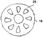
图3中示出了具有阀体11a的阀装置,其包围阀控制空间12a,其中闭合体17可移动地安装在其中。闭合体17包括磁致激活芯部17a和包围或包住芯部17a并且连接到轴承垫圈18上的尤其是塑料制成的包装物17b。轴承垫圈在图4中以平面图表示。它的外周安装在阀体11a上,并且整体上是弹性的,使得它将闭合体17保持在所表示的中间位置中。轴承垫圈18包括多个开口25,其允许流体的流通被阀控制。FIG. 3 shows a valve arrangement with a
闭合体17的端部19,20的形状和设计使得它们可以关闭进料口1a或排出口2a,同时有闭合体17的相应偏转和轴承垫圈18的弹性变形。The ends 19 , 20 of the closing
为此,闭合体17的包装物17b可由弹性材料,特别是例如弹性体组成。闭合体17的磁芯17a通过磁体装置A',B'可以受到将闭合体17沿进料口1a的方向或排出口2a的方向拉动的力,以使阀进入第一或第二封闭位置。For this purpose, the
图5中的阀体11a以三维视图表示为包围阀控制空间12a以及进料通道1和排出通道2的壳体,以及包括磁体装置A'和B'的壳体16a。如果阀装置的一部分被设计为一次性的阀,则壳体11a可以与壳体部分16a分离,使得磁体装置可以被使用多次或继续使用,而包括阀控制空间12的阀的部件可以被更换。The
图3示出了与流体控制装置结合的根据本发明的阀,该流体控制装置同样是根据本发明并且其包括导管21,穿过导管21的旋转轴22以及未详细表示的冲洗装置,其中具有阀体11a的阀、阀控制空间12a和阀驱动器的机械部件形成冲洗装置的一部分。冲洗装置的其它部分例如可以是未详细表示的冲洗剂泵和冲洗剂储存器。进料通道或排出通道1,2可以连接到导管21,以便允许冲洗剂通过阀的合适的驱动被导入或导出导管。轴22的扭曲的结构也在图3中被标识,取决于轴的旋转速度和轴的磨损,这可能导致不同的吸力和压力效应。Fig. 3 shows a valve according to the invention in combination with a fluid control device, which is also according to the invention and which comprises a
图6示出了具有输送通道的电磁阀,流体通过该输送通道在进料口1'和排出口2'之间流动。封闭体50可以在第一封闭位置和第二封闭位置之间的输送通道88内被驱动,其中在第一封闭位置中第一封闭表面51关闭阀开口51a,而在第二封闭位置中封闭表面52关闭阀开口52a。Figure 6 shows a solenoid valve with a delivery channel through which fluid flows between the feed port 1' and the discharge port 2'. The closing
可以由两个阀驱动线圈55,56的磁场驱动的两个衔铁体53,54被集成到封闭体50中。分离装置的磁体86以与衔铁体53,54平齐的方式轴向地布置在衔铁体53,54之间。具有磁体86的衔铁体设置有公共的固体包装物87。附着于固体包装物87的颗粒通过示例的方式标记为15。Two
在没有阀驱动线圈的激励的情况下,保持弹簧57,58将封闭体保持在阀打开的中间位置。两个滑动轴承59,60设置在阀壳体的端部处,用于引导封闭体50。Retaining springs 57, 58 hold the closure body in the valve open neutral position without energization of the valve drive coil. Two sliding
图7示出了具有进料口1”、排出口2”和封闭体50'的阀。封闭体50'可以在第一封闭位置和第二封闭位置之间的输送通道88'内被驱动,其中第一封闭表面51'在第一封闭位置关闭阀开口51a',而封闭表面52'在第二封闭位置关闭阀开口52a'。封闭体50'通过弹性可渗透盘61安装在阀的壳体中,并保持在打开的中间位置。盘61将连接在封闭体50'中的分离磁体86',86”携带至阀驱动衔铁62,63,并与这些一起被保护层包围。Figure 7 shows a valve with an
阀驱动衔铁62,63可以在线圈64,65的场中被驱动。颗粒可以积聚在保护层上的分离磁体上的输送通道中并且可以被保留在那里。The
导管装置现在以几种选择方案在图8-12中表示。The catheter device is now shown in Figures 8-12 in several options.
图8示出了导管装置,其包括驱动单元,该驱动单元具有可驱动旋转并且驱动导管68中的旋转轴67的驱动衔铁66。径向地朝着外部设计为进料通道69并径向地朝着内部设计为返回通道70的内腔在导管68内并朝着导管的外包络体彼此同心地布置。进料通道69和返回通道70通过软管状分隔壁71而彼此分离。FIG. 8 shows a catheter device comprising a drive unit having a
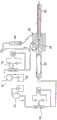
通过体积控制的蠕动泵72将冲洗液从储存器73泵送穿过被设计为插管的内腔74,以及阀75。两个磁体76和77用于阀的驱动,并且是通过压力开关78被激活,目的是在进料通道69中保持恒定的压力。用于此的流体被引导通过阀75并通过驱动衔铁66的壳体,通过被设计为输送通道的内腔79并且通过颗粒被积极地从流体中过滤掉的分离装置80。分离装置80可以构造为图6所示的分离装置。从那里,流体通过进料通道69径向向外流入导管68并通过返回通道70径向向内流动,并且从那里进入将流体吸入并引入储存器82的蠕动泵81。蠕动泵81也可以用于反冲洗并且为此目的可以以这样的方式操作,使得其将流体递送至返回通道70并且从那里经由进料通道69,通过分离装置回到阀75进入储存器73,以便例如从分离装置中除去捕获的颗粒。Irrigation fluid is pumped from the
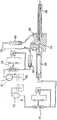
图9示出了与图8类似的构造,其中除了在驱动衔铁66的前面并且在蠕动泵72的后面的阀75之外,第二阀75'布置在返回通道70和蠕动泵81之间。在图8中应用了冲洗系统,其中由于安装部件而在返回时没有产生不希望的真空,还可以在图9应用冲洗系统,其中在返回时产生了不期望的真空(例如由于柔性轴的转动方向)。这种真空被传感器识别出,然后该传感器通过将阀75'关闭到底部,确保没有介质通过泵81从容器82排出到冲洗回路中。分离装置因此被布置在两个阀之间,并且也在流体输送装置之间,其中至少一个流体输送装置,特别地,两个流体输送装置可以相对于流体的输送方向切换,以便逆转流动方向。关于根据图10的构造,与图8中的构造相比,仅仅是蠕动泵72已经被允许重力冲洗的储存器83所替代,通过流体流过阀75并由于重力而进一步流到导管68。导管68内的旋转轴84由于其基于扭绞线的绞合/扭曲构造而具有螺旋(盘绕的)外部结构,其在旋转时在远离驱动衔铁66的方向上给予其自身泵送效应。具有体积控制的蠕动泵72和储存器73的另一种变型在图10的右侧、虚线85的右侧表示,用于将流体供给到导管68。蠕动泵将流体输送到例如被引入到患者的身体中的导管的内部,并且在具有转子85a的心脏泵85处终止。心脏泵例如可以被径向压缩,这就是说整体上颗粒可特别容易进入其中。然后流体从那里流回。在每个情况下,分离装置80可以沿流动方向设置在导管68的上游、在其与输送装置73,83之间,特别地,在任何情况下的心脏泵85的上游。FIG. 9 shows a configuration similar to that of FIG. 8 , in which a
图11示出了类似于图9的布置,其中设想自流输送83代替蠕动泵72,其中在正常操作中,流体经由阀从其中引导到导管68中,并且首先在那里径向向外通过进料通道69,径向向内进入返回通道70,以及从那里到将流体吸入并引入储存器82的蠕动泵81。返回通道70和蠕动泵81之间的流体首先经过设置在返回通道和驱动衔铁66的壳体之间的分离装置80。此后,流体流经驱动衔铁66到蠕动泵81。驱动衔铁的安装可能相对不敏感,因此流体的流通方向具有次要的意义。重要的是驱动衔铁的外壳被供应有流体,以确保良好的润滑。所选择的布置还确保了在这种情况下旋转轴84的磁磨损颗粒不能损坏驱动衔铁的轴承。Figure 11 shows an arrangement similar to that of Figure 9, where
图12示出了类似于图9的结构,其中另一分离装置80'确保阀75'的密封表面的功能不受粘附颗粒的危害。Fig. 12 shows a structure similar to that of Fig. 9, wherein another
此外,本申请涉及以下方面。Furthermore, the present application relates to the following aspects.
1.一种具有阀控制空间(12,12a)的用于控制尤其是通过导管的流体流的阀,其中进料通道(1)从进料口(1a)伸出,并且排出通道(2)从排出口(2a)伸出,且具有封闭元件(5,13,17),该封闭元件在阀控制空间(12,12a)中以可控制的方式可移动并且在至少一个第一位置(I)关闭排出口(2a),在至少一个第二位置(II)关闭进料口(1a),并且在至少一个第三位置(III)保持进料口(1a)和排出口(2a)之间的连接通道打开,其中提供有阀驱动器(A,B,A',B',3,14,18),其选择性地移动封闭元件(5,13,17)至少进入所述第一、第二或第三位置。1. A valve for controlling fluid flow, especially through conduits, with a valve control space (12, 12a), wherein a feed channel (1) protrudes from a feed opening (1a), and a discharge channel (2) Projecting from the discharge opening (2a) and having a closing element (5, 13, 17) controllably movable in the valve control space (12, 12a) and in at least one first position (I ) close the discharge port (2a), close the feed port (1a) in at least one second position (II), and maintain the gap between the feed port (1a) and the discharge port (2a) in at least one third position (III) The connecting channel of the 1 is opened, wherein valve actuators (A, B, A', B', 3, 14, 18) are provided, which selectively move the closing elements (5, 13, 17) into at least the first, second Second or third position.
2.根据方面1所述的阀,其特征在于,封闭元件(5,133)的第三位置(III)位于第一和第二位置之间。2. Valve according to
3.根据方面1或2所述的阀,其特征在于,阀控制空间(12,12a)可以与封闭元件(5,13,17)的阀驱动器分离。3. Valve according to
4.根据方面1和以下之一所述的阀,其特征在于,除了进料口(1a)和排出口(2a)之外的阀控制空间(12,12a)在所有侧面以液密的方式被封闭。4. The valve according to
5.根据方面1或以下任一所述的阀,其特征在于,封闭元件(5,13,17)包括可移动膜(5),该可移动膜以液密的方式封闭阀控制空间(12)并且是以使得进料口(1a)或排出口(2a)可以选择性地被膜(5)的部件关闭的方式而可偏转。5. Valve according to
6.根据方面5所述的阀,其特征在于,阀驱动器(3,14,18,A,A',B,B')的驱动杆(3,14)至少在第一和第二位置使所述膜(5)偏转。6. A valve according to
7.根据方面1或以下任一所述的阀,其特征在于,封闭元件(5,13,17)可由磁力作用阀驱动器(A,A',B,B')驱动。7. A valve according to
8.根据方面7所述的阀,其特征在于,设置在阀控制空间(12,12a)中的封闭元件(5,13,17)是磁致激活的并且与阀驱动器(A,A',B,B')的磁场相互作用。8. The valve according to
9.根据方面6和7所述的阀,其特征在于,驱动杆(3,14)可被磁力驱动。9. Valve according to
10.根据方面7所述的阀,其特征在于,除了进料口和排出口(1a,2a)之外,阀控制空间(12,12a)以及机械连接到封闭元件(5,13,17)的阀驱动器的部件(3,14,18)以液密的方式封闭,并且可以与阀驱动器的磁场产生装置(A,A',B,B')分离。10. Valve according to
11.根据方面1或以下任一项所述的阀,其特征在于,封闭元件通过弹性弹簧元件(10,18)移动,优选地移动到第三位置(III)。11. Valve according to
12.根据方面1或以下任一项所述的阀,其特征在于,磁体(13”,13”',13””)作为分离装置的一部分直接设置在阀控制空间(12,12a)上,特别地,在封闭元件(5,15,17)的内部。12. The valve according to
13.根据方面12所述的阀,其特征在于,一个磁体/多个磁体(13”,13”',13””)与所述一个阀驱动器的驱动衔铁(53,54,62,63)分开并且特别是远离驱动衔铁(53,54,62,63)设置。13. Valve according to
14.一种导管,包括根据前述方面中至少一项所述的阀,其特征在于,所述阀控制空间可以与所述封闭元件的阀驱动器分离。14. A catheter comprising a valve according to at least one of the preceding aspects, wherein the valve control space is separable from the valve driver of the closure element.
15.一种用于与流动流体连接的阀(75,75')的保护装置,其特征在于,用于阻止位于流体中的颗粒并具有至少一个磁体元件(86,86',86”)的分离装置(80)沿着用于所述流体,特别地,用于导管的所述流动通道(79,88)被设置,设置方式为以远离阀特别是与此分离的方式。15. A protective device for a valve (75, 75') in connection with a flowing fluid, characterized by a protection device for blocking particles located in the fluid and having at least one magnet element (86, 86', 86") Separation means (80) are provided along said flow channels (79, 88) for said fluid, in particular for conduits, in such a way as to be remote from the valve, in particular separate therefrom.
Claims (23)
Translated fromChineseApplications Claiming Priority (6)
| Application Number | Priority Date | Filing Date | Title |
|---|---|---|---|
| EP15152205.9 | 2015-01-22 | ||
| EP15152205.9AEP3047911A1 (en) | 2015-01-22 | 2015-01-22 | Separating device for retention of magnetic particles in a fluid and protection device for a functional element |
| EP15152201.8 | 2015-01-22 | ||
| EP15152201.8AEP3047873A1 (en) | 2015-01-22 | 2015-01-22 | Magnetically actuated valve for controlling the flow of a fluid through a catheter |
| CN201680006875.XACN107206225B (en) | 2015-01-22 | 2016-01-22 | Conduit device including valve for controlling fluid flow through conduit |
| PCT/EP2016/051358WO2016116608A2 (en) | 2015-01-22 | 2016-01-22 | Catheter device, comprising a valve for controlling a fluid flow through a catheter |
Related Parent Applications (1)
| Application Number | Title | Priority Date | Filing Date |
|---|---|---|---|
| CN201680006875.XADivisionCN107206225B (en) | 2015-01-22 | 2016-01-22 | Conduit device including valve for controlling fluid flow through conduit |
Publications (2)
| Publication Number | Publication Date |
|---|---|
| CN111905231Atrue CN111905231A (en) | 2020-11-10 |
| CN111905231B CN111905231B (en) | 2022-10-04 |
Family
ID=55229682
Family Applications (9)
| Application Number | Title | Priority Date | Filing Date |
|---|---|---|---|
| CN202010855332.3AActiveCN111905231B (en) | 2015-01-22 | 2016-01-22 | Conduit device including valve for controlling fluid flow through conduit |
| CN202310814930.XAPendingCN116808431A (en) | 2015-01-22 | 2016-01-22 | Catheter device comprising a separation device for entrapping magnetic particles contained in a fluid and a protection device for functional elements |
| CN202011429973.9AActiveCN112569451B (en) | 2015-01-22 | 2016-01-22 | Catheter device comprising separation means for retaining magnetic particles contained in a fluid and protection means for functional elements |
| CN202310263436.9APendingCN116271417A (en) | 2015-01-22 | 2016-01-22 | Catheter device including a valve for controlling fluid flow through the catheter |
| CN202110513424.8AActiveCN113181548B (en) | 2015-01-22 | 2016-01-22 | Catheter device including separation device for retaining magnetic particles contained in fluid and protection device for functional elements |
| CN202411552638.6APendingCN119185774A (en) | 2015-01-22 | 2016-01-22 | Catheter device comprising a separation device for entrapping magnetic particles contained in a fluid and a protection device for functional elements |
| CN201680006882.XAActiveCN107206136B (en) | 2015-01-22 | 2016-01-22 | Catheter device including separation device for retaining magnetic particles contained in fluid and protection device for functional elements |
| CN202010855035.9AActiveCN111905230B (en) | 2015-01-22 | 2016-01-22 | Catheter device comprising a valve for controlling a fluid flow through a catheter |
| CN201680006875.XAActiveCN107206225B (en) | 2015-01-22 | 2016-01-22 | Conduit device including valve for controlling fluid flow through conduit |
Family Applications After (8)
| Application Number | Title | Priority Date | Filing Date |
|---|---|---|---|
| CN202310814930.XAPendingCN116808431A (en) | 2015-01-22 | 2016-01-22 | Catheter device comprising a separation device for entrapping magnetic particles contained in a fluid and a protection device for functional elements |
| CN202011429973.9AActiveCN112569451B (en) | 2015-01-22 | 2016-01-22 | Catheter device comprising separation means for retaining magnetic particles contained in a fluid and protection means for functional elements |
| CN202310263436.9APendingCN116271417A (en) | 2015-01-22 | 2016-01-22 | Catheter device including a valve for controlling fluid flow through the catheter |
| CN202110513424.8AActiveCN113181548B (en) | 2015-01-22 | 2016-01-22 | Catheter device including separation device for retaining magnetic particles contained in fluid and protection device for functional elements |
| CN202411552638.6APendingCN119185774A (en) | 2015-01-22 | 2016-01-22 | Catheter device comprising a separation device for entrapping magnetic particles contained in a fluid and a protection device for functional elements |
| CN201680006882.XAActiveCN107206136B (en) | 2015-01-22 | 2016-01-22 | Catheter device including separation device for retaining magnetic particles contained in fluid and protection device for functional elements |
| CN202010855035.9AActiveCN111905230B (en) | 2015-01-22 | 2016-01-22 | Catheter device comprising a valve for controlling a fluid flow through a catheter |
| CN201680006875.XAActiveCN107206225B (en) | 2015-01-22 | 2016-01-22 | Conduit device including valve for controlling fluid flow through conduit |
Country Status (9)
| Country | Link |
|---|---|
| US (5) | US10518010B2 (en) |
| EP (5) | EP4588502A2 (en) |
| JP (10) | JP6716579B2 (en) |
| KR (5) | KR102510791B1 (en) |
| CN (9) | CN111905231B (en) |
| CA (2) | CA2974584A1 (en) |
| DK (3) | DK3572120T3 (en) |
| ES (2) | ES2758077T3 (en) |
| WO (2) | WO2016116630A2 (en) |
Families Citing this family (24)
| Publication number | Priority date | Publication date | Assignee | Title |
|---|---|---|---|---|
| CN102380135A (en) | 2006-03-23 | 2012-03-21 | 宾州研究基金会 | Heart assist device with expandable impeller pump |
| US9358329B2 (en) | 2012-07-03 | 2016-06-07 | Thoratec Corporation | Catheter pump |
| US11160970B2 (en) | 2016-07-21 | 2021-11-02 | Tc1 Llc | Fluid seals for catheter pump motor assembly |
| EP3808401A1 (en) | 2016-07-21 | 2021-04-21 | Tc1 Llc | Gas-filled chamber for catheter pump motor assembly |
| CN109843369B (en)* | 2016-10-17 | 2021-11-09 | 拜耳医药保健有限公司 | Fluid control valve and manifold |
| JP7128818B2 (en) | 2016-12-19 | 2022-08-31 | アビオメド インコーポレイテッド | Heart pump with passive purge system |
| CA3066361A1 (en) | 2017-06-07 | 2018-12-13 | Shifamed Holdings, Llc | Intravascular fluid movement devices, systems, and methods of use |
| WO2019094963A1 (en) | 2017-11-13 | 2019-05-16 | Shifamed Holdings, Llc | Intravascular fluid movement devices, systems, and methods of use |
| CN112004563B (en) | 2018-02-01 | 2024-08-06 | 施菲姆德控股有限责任公司 | Intravascular blood pump and methods of use and manufacture |
| US12161857B2 (en) | 2018-07-31 | 2024-12-10 | Shifamed Holdings, Llc | Intravascular blood pumps and methods of use |
| WO2020073047A1 (en) | 2018-10-05 | 2020-04-09 | Shifamed Holdings, Llc | Intravascular blood pumps and methods of use |
| WO2021011473A1 (en) | 2019-07-12 | 2021-01-21 | Shifamed Holdings, Llc | Intravascular blood pumps and methods of manufacture and use |
| US11654275B2 (en) | 2019-07-22 | 2023-05-23 | Shifamed Holdings, Llc | Intravascular blood pumps with struts and methods of use and manufacture |
| EP4501393A3 (en) | 2019-09-25 | 2025-04-09 | Shifamed Holdings, LLC | Catheter blood pumps and collapsible pump housings |
| WO2021062265A1 (en) | 2019-09-25 | 2021-04-01 | Shifamed Holdings, Llc | Intravascular blood pump systems and methods of use and control thereof |
| US12121713B2 (en) | 2019-09-25 | 2024-10-22 | Shifamed Holdings, Llc | Catheter blood pumps and collapsible blood conduits |
| CN110604850B (en)* | 2019-10-28 | 2024-08-27 | 广东安特医疗有限公司 | Three-way valve and infusion device |
| EP4072650A4 (en) | 2019-12-11 | 2024-01-10 | Shifamed Holdings, LLC | Descending aorta and vena cava blood pumps |
| CN111821528A (en)* | 2020-06-16 | 2020-10-27 | 北京工业大学 | Functional artificial left ventricular system |
| CN112791305A (en)* | 2021-01-22 | 2021-05-14 | 苏州心擎医疗技术有限公司 | Blood pump and power transmission assembly thereof |
| DE102021001563B4 (en) | 2021-03-25 | 2022-12-22 | Uromed Kurt Drews Kg | Catheter valve for controlling fluid flow of a medium |
| WO2023284339A1 (en)* | 2021-07-12 | 2023-01-19 | 苏州心擎医疗技术有限公司 | Device used for assisting heart during cardiac functional failure |
| WO2023283751A1 (en)* | 2021-07-12 | 2023-01-19 | 苏州心擎医疗技术有限公司 | Device for assisting heart in event of heart failure |
| CN113926074B (en)* | 2021-11-04 | 2023-10-31 | 丰凯利医疗器械(上海)有限公司 | Diversion transmission device and blood pump system |
Citations (7)
| Publication number | Priority date | Publication date | Assignee | Title |
|---|---|---|---|---|
| US3642004A (en)* | 1970-01-05 | 1972-02-15 | Life Support Equipment Corp | Urethral valve |
| DE3506493A1 (en)* | 1984-03-07 | 1985-09-19 | Eaton SAM, Monaco | Solenoid-operated multi-way valve |
| US20040055652A1 (en)* | 2002-09-20 | 2004-03-25 | John Erickson | Dosage control apparatus |
| DE20302911U1 (en)* | 2003-02-22 | 2004-07-01 | Hengst Gmbh & Co.Kg | Valve for motor vehicle internal combustion engine has oil collecting chamber with actuator for valve contained in casing |
| CN101761651A (en)* | 2008-12-22 | 2010-06-30 | 印科瓦技术股份有限公司 | Poppet valve operated by an electrohydraulic poppet pilot valve |
| CN102481445A (en)* | 2009-06-22 | 2012-05-30 | Np医药公司 | Medical valve with improved back-pressure sealing |
| US20120178985A1 (en)* | 2011-01-06 | 2012-07-12 | Walters Daniel A | Percutaneous heart pump |
Family Cites Families (58)
| Publication number | Priority date | Publication date | Assignee | Title |
|---|---|---|---|---|
| GB768451A (en)* | 1954-03-22 | 1957-02-20 | Jones George Henry | Method of and means for magnetically separating solid magnetic particles from a fluid current |
| US3570807A (en)* | 1969-01-14 | 1971-03-16 | Bell Aerospace Corp | Electromechanical control valve |
| CH591178A5 (en)* | 1972-11-03 | 1977-09-15 | Anvar | |
| US4078998A (en)* | 1974-10-21 | 1978-03-14 | Robin Roy Oder | Magnetic separator |
| US4038982A (en)* | 1975-12-03 | 1977-08-02 | Burron Medical Products, Inc. | Electrically controlled intravenous infusion set |
| US4357237A (en) | 1979-11-28 | 1982-11-02 | Sanderson Charles H | Device for the magnetic treatment of water and liquid and gaseous fuels |
| CA1124153A (en)* | 1979-12-14 | 1982-05-25 | James E. Young | Flow regulating device for arterial catheter systems |
| US4375407A (en)* | 1981-06-22 | 1983-03-01 | The Franklin Institute | High gradient magnetic separation device |
| US4596558A (en)* | 1985-09-13 | 1986-06-24 | Queen's University At Kingston | Pulsed external medication dispenser |
| US4895557A (en)* | 1987-12-07 | 1990-01-23 | Nimbus Medical, Inc. | Drive mechanism for powering intravascular blood pumps |
| JPH069669Y2 (en)* | 1989-03-03 | 1994-03-16 | 株式会社三陽電機製作所 | Hemodialysis machine |
| DE4123091C2 (en)* | 1991-07-12 | 1994-05-11 | Anschuetz & Co Gmbh | Valve and its use for infusion pumps |
| DE4224389B4 (en)* | 1992-07-23 | 2004-02-19 | AVS, Ing. J.C. Römer GmbH | Valve with T-shaped or N-shaped, rocker-like valve element |
| US5655665A (en)* | 1994-12-09 | 1997-08-12 | Georgia Tech Research Corporation | Fully integrated micromachined magnetic particle manipulator and separator |
| JPH0957149A (en)* | 1995-08-28 | 1997-03-04 | Furukawa Electric Co Ltd:The | Magnetic powder remover |
| NL1003056C2 (en)* | 1996-05-07 | 1997-11-10 | Cordis Europ | Suction catheter with hemostasis device. |
| DE19717790A1 (en) | 1997-04-26 | 1998-10-29 | Convergenza Ag | Device with a therapeutic catheter |
| CN1105850C (en)* | 1998-06-29 | 2003-04-16 | 斯冈株式会社 | Channel Switching apparatus |
| US6245007B1 (en)* | 1999-01-28 | 2001-06-12 | Terumo Cardiovascular Systems Corporation | Blood pump |
| AU7354400A (en)* | 1999-09-03 | 2001-04-10 | A-Med Systems, Inc. | Guidable intravascular blood pump and related methods |
| US7655016B2 (en)* | 1999-09-17 | 2010-02-02 | Covidien | Mechanical pump for removal of fragmented matter and methods of manufacture and use |
| IT1316850B1 (en)* | 2000-03-24 | 2003-05-12 | Curzio Aldo Magri | DEVICE FOR THE DISPENSING OF FOOD FLUIDS, PARTICULARLY AUTOMATIC OR SEMI-AUTOMATIC DISPENSERS OF HOT OR COLD DRINKS |
| US6673051B2 (en)* | 2001-04-02 | 2004-01-06 | Hook Research Foundation | Magnetic valve bladder cycler drainage system and use method with urinary catheters |
| US20030120202A1 (en)* | 2001-12-21 | 2003-06-26 | Gordon Lucas S. | Magnetic extracorporeal circuit for removal of medical agents |
| DE502004007022D1 (en)* | 2003-03-06 | 2008-06-19 | Roemer J C Avs Gmbh | Pneumatically actuated valve |
| CA2559494C (en)* | 2004-03-19 | 2013-05-21 | Medical Components, Inc. | Magnet cuff for vascular catheters and bloodlines |
| DE102004034480A1 (en)* | 2004-07-15 | 2006-02-09 | Microcuff Gmbh | Valve for filling low pressure balloon catheter has magnets pressing the shut-off body against the edge of opening |
| WO2006127508A2 (en)* | 2005-05-20 | 2006-11-30 | Wilson Greatbatch Technologies Inc. | Improved configuration for drug delivery systems |
| US7604748B2 (en)* | 2005-10-20 | 2009-10-20 | Eclipse Magnetics Limited | Magnetic filter |
| US8127791B2 (en)* | 2005-12-21 | 2012-03-06 | Saturn Electronics & Engineering, Inc. | Solenoid operated fluid control valve |
| AU2007266459B2 (en) | 2006-05-31 | 2013-01-17 | Star Bp, Inc. | Heart assist device |
| WO2008101352A1 (en)* | 2007-02-22 | 2008-08-28 | Simonson Roger M | Magnetic filter and magnetic filtering assembly |
| ATE480274T1 (en) | 2007-10-08 | 2010-09-15 | Ais Gmbh Aachen Innovative Sol | CATHETER DEVICE |
| JP5670197B2 (en)* | 2007-12-07 | 2015-02-18 | ミルテンイ バイオテック ゲーエムベーハー | Sample processing system and method |
| US8556843B2 (en)* | 2008-02-02 | 2013-10-15 | AccelDx | Blood purification method and apparatus for the treatment of malaria |
| JP2011512997A (en) | 2008-03-05 | 2011-04-28 | ホック,ロバート | Pressure sensing catheter |
| US8491541B2 (en)* | 2008-09-30 | 2013-07-23 | Covidien Lp | Ball-valve actuation mechanism |
| US8561638B2 (en) | 2008-12-02 | 2013-10-22 | Piolax Inc. | Check valve |
| US8801697B2 (en)* | 2009-04-20 | 2014-08-12 | Cheiron Japan Co. | Urination control device |
| EP2246078A1 (en)* | 2009-04-29 | 2010-11-03 | ECP Entwicklungsgesellschaft mbH | Shaft assembly with a shaft which moves within a fluid-filled casing |
| EP2248544A1 (en)* | 2009-05-05 | 2010-11-10 | ECP Entwicklungsgesellschaft mbH | Fluid pump with variable circumference, particularly for medical use |
| CN105147347B (en)* | 2010-03-06 | 2018-06-12 | 新融合血管系统有限公司 | Recycle catheter kit |
| EP2368639A1 (en)* | 2010-03-23 | 2011-09-28 | Siemens Aktiengesellschaft | Method and device for magnetically separating a fluid |
| DE102010023131A1 (en)* | 2010-06-09 | 2011-12-15 | Basf Se | Arrangement and method for separating magnetisable particles from a liquid |
| EP2422735A1 (en)* | 2010-08-27 | 2012-02-29 | ECP Entwicklungsgesellschaft mbH | Implantable blood transportation device, manipulation device and coupling device |
| US20120145641A1 (en)* | 2010-08-31 | 2012-06-14 | Justin Rebo | Method and Apparatus for removing senescent cells |
| DE102010042723A1 (en)* | 2010-10-20 | 2012-04-26 | Miltenyi Biotec Gmbh | Apparatus and method for separating Neél and Brown magnetic particles |
| JP2014515694A (en)* | 2011-03-11 | 2014-07-03 | ギーシェン ヤン、 | Magnetic particle scavenging apparatus and method |
| JP3178785U (en)* | 2011-12-27 | 2012-10-04 | ファハド,アルカンハル | Portable hemodialysis machine |
| PL2834009T3 (en)* | 2012-04-03 | 2018-05-30 | Spiro Enterprises B.V. | Fluid circulation system for circulating an amount of fluid comprising a magnetic separator for separating suspended particles having ferromagnetic properties, and corresponding method |
| US20140107589A1 (en)* | 2012-10-17 | 2014-04-17 | Farid Amirouche | Electromagnetically actuated valve and related methods of use |
| US9242077B2 (en)* | 2013-03-12 | 2016-01-26 | DePuy Synthes Products, Inc. | Dynamic adjustment tool for programming an implantable valve |
| WO2014164136A1 (en)* | 2013-03-13 | 2014-10-09 | Thoratec Corporation | Fluid handling system |
| US9719738B2 (en) | 2013-03-14 | 2017-08-01 | Hydroflux Technology, Llc | Apparatus and method for applying magnetic fields to fluid flows |
| US9044586B2 (en)* | 2013-03-15 | 2015-06-02 | Fresenius Medical Care Holdings, Inc. | Dialysis control valve having self-cleaning mode |
| DE202013104711U1 (en) | 2013-10-18 | 2013-11-06 | Fang Zhengda | A one-way valve |
| US10286196B2 (en)* | 2016-06-30 | 2019-05-14 | Integra Lifesciences Switzerland Sàrl | Device to control magnetic rotor of a programmable hydrocephalus valve |
| GB2606966B (en)* | 2018-10-31 | 2023-06-14 | Ingenion Medical Ltd | An intraurethral magnetic valve and associated parts |
- 2016
- 2016-01-22DKDK19185354.8Tpatent/DK3572120T3/enactive
- 2016-01-22JPJP2017538967Apatent/JP6716579B2/enactiveActive
- 2016-01-22ESES16701465Tpatent/ES2758077T3/enactiveActive
- 2016-01-22CNCN202010855332.3Apatent/CN111905231B/enactiveActive
- 2016-01-22WOPCT/EP2016/051391patent/WO2016116630A2/ennot_activeCeased
- 2016-01-22WOPCT/EP2016/051358patent/WO2016116608A2/ennot_activeCeased
- 2016-01-22KRKR1020177022929Apatent/KR102510791B1/enactiveActive
- 2016-01-22USUS15/545,003patent/US10518010B2/enactiveActive
- 2016-01-22CNCN202310814930.XApatent/CN116808431A/enactivePending
- 2016-01-22CACA2974584Apatent/CA2974584A1/enactivePending
- 2016-01-22EPEP25181307.7Apatent/EP4588502A2/enactivePending
- 2016-01-22USUS15/545,037patent/US10960117B2/enactiveActive
- 2016-01-22EPEP24169911.5Apatent/EP4434571A3/enactivePending
- 2016-01-22CNCN202011429973.9Apatent/CN112569451B/enactiveActive
- 2016-01-22ESES19185354Tpatent/ES2985131T3/enactiveActive
- 2016-01-22EPEP16701474.5Apatent/EP3247500B1/enactiveActive
- 2016-01-22CNCN202310263436.9Apatent/CN116271417A/enactivePending
- 2016-01-22DKDK16701465Tpatent/DK3247450T3/enactive
- 2016-01-22KRKR1020237020826Apatent/KR20230097216A/enactivePending
- 2016-01-22CNCN202110513424.8Apatent/CN113181548B/enactiveActive
- 2016-01-22KRKR1020237008679Apatent/KR102723289B1/enactiveActive
- 2016-01-22KRKR1020177022700Apatent/KR102547508B1/enactiveActive
- 2016-01-22CNCN202411552638.6Apatent/CN119185774A/enactivePending
- 2016-01-22KRKR1020247035499Apatent/KR20240159976A/enactivePending
- 2016-01-22CNCN201680006882.XApatent/CN107206136B/enactiveActive
- 2016-01-22EPEP16701465.3Apatent/EP3247450B1/enactiveActive
- 2016-01-22EPEP19185354.8Apatent/EP3572120B1/enactiveActive
- 2016-01-22CNCN202010855035.9Apatent/CN111905230B/enactiveActive
- 2016-01-22CNCN201680006875.XApatent/CN107206225B/enactiveActive
- 2016-01-22DKDK16701474.5Tpatent/DK3247500T3/enactive
- 2016-01-22CACA2973892Apatent/CA2973892A1/enactivePending
- 2016-01-22JPJP2017538959Apatent/JP6599997B2/enactiveActive
- 2019
- 2019-10-03JPJP2019182662Apatent/JP6905023B2/enactiveActive
- 2019-11-25USUS16/694,518patent/US11045641B2/enactiveActive
- 2020
- 2020-06-10JPJP2020100567Apatent/JP6938725B2/enactiveActive
- 2021
- 2021-02-12USUS17/174,455patent/US20210228860A1/enactivePending
- 2021-05-17USUS17/322,374patent/US20210339010A1/enactivePending
- 2021-06-24JPJP2021104512Apatent/JP2021180845A/enactivePending
- 2021-09-01JPJP2021142284Apatent/JP7481307B2/enactiveActive
- 2022
- 2022-08-08JPJP2022126515Apatent/JP7453290B2/enactiveActive
- 2023
- 2023-12-26JPJP2023219040Apatent/JP2024039657A/enactivePending
- 2024
- 2024-03-07JPJP2024034531Apatent/JP7719226B2/enactiveActive
- 2025
- 2025-07-24JPJP2025123699Apatent/JP2025137754A/enactivePending
Patent Citations (7)
| Publication number | Priority date | Publication date | Assignee | Title |
|---|---|---|---|---|
| US3642004A (en)* | 1970-01-05 | 1972-02-15 | Life Support Equipment Corp | Urethral valve |
| DE3506493A1 (en)* | 1984-03-07 | 1985-09-19 | Eaton SAM, Monaco | Solenoid-operated multi-way valve |
| US20040055652A1 (en)* | 2002-09-20 | 2004-03-25 | John Erickson | Dosage control apparatus |
| DE20302911U1 (en)* | 2003-02-22 | 2004-07-01 | Hengst Gmbh & Co.Kg | Valve for motor vehicle internal combustion engine has oil collecting chamber with actuator for valve contained in casing |
| CN101761651A (en)* | 2008-12-22 | 2010-06-30 | 印科瓦技术股份有限公司 | Poppet valve operated by an electrohydraulic poppet pilot valve |
| CN102481445A (en)* | 2009-06-22 | 2012-05-30 | Np医药公司 | Medical valve with improved back-pressure sealing |
| US20120178985A1 (en)* | 2011-01-06 | 2012-07-12 | Walters Daniel A | Percutaneous heart pump |
Also Published As
Similar Documents
| Publication | Publication Date | Title |
|---|---|---|
| CN107206225B (en) | Conduit device including valve for controlling fluid flow through conduit | |
| HK1243009B (en) | Catheter device, comprising a valve for controlling a fluid flow through a catheter | |
| HK1243009A1 (en) | Catheter device, comprising a valve for controlling a fluid flow through a catheter | |
| HK40012181A (en) | Catheter device, comprising a valve for controlling a flow of a fluid through a catheter | |
| HK40012181B (en) | Catheter device, comprising a valve for controlling a flow of a fluid through a catheter | |
| HK1243008A1 (en) | Catheter device comprising a separating device for retaining magnetic particles contained in a fluid and protection device for a functional element | |
| HK1243008B (en) | Catheter device comprising a separating device for retaining magnetic particles contained in a fluid and protection device for a functional element |
Legal Events
| Date | Code | Title | Description |
|---|---|---|---|
| PB01 | Publication | ||
| PB01 | Publication | ||
| SE01 | Entry into force of request for substantive examination | ||
| SE01 | Entry into force of request for substantive examination | ||
| GR01 | Patent grant | ||
| GR01 | Patent grant |