CN111904858A - an automatic injection device - Google Patents
an automatic injection deviceDownload PDFInfo
- Publication number
- CN111904858A CN111904858ACN202010872467.0ACN202010872467ACN111904858ACN 111904858 ACN111904858 ACN 111904858ACN 202010872467 ACN202010872467 ACN 202010872467ACN 111904858 ACN111904858 ACN 111904858A
- Authority
- CN
- China
- Prior art keywords
- needle
- turntable
- needle assembly
- push rod
- injection device
- Prior art date
- Legal status (The legal status is an assumption and is not a legal conclusion. Google has not performed a legal analysis and makes no representation as to the accuracy of the status listed.)
- Pending
Links
Images


Classifications
- A—HUMAN NECESSITIES
- A61—MEDICAL OR VETERINARY SCIENCE; HYGIENE
- A61J—CONTAINERS SPECIALLY ADAPTED FOR MEDICAL OR PHARMACEUTICAL PURPOSES; DEVICES OR METHODS SPECIALLY ADAPTED FOR BRINGING PHARMACEUTICAL PRODUCTS INTO PARTICULAR PHYSICAL OR ADMINISTERING FORMS; DEVICES FOR ADMINISTERING FOOD OR MEDICINES ORALLY; BABY COMFORTERS; DEVICES FOR RECEIVING SPITTLE
- A61J1/00—Containers specially adapted for medical or pharmaceutical purposes
- A61J1/14—Details; Accessories therefor
- A61J1/20—Arrangements for transferring or mixing fluids, e.g. from vial to syringe
- A61J1/2003—Accessories used in combination with means for transfer or mixing of fluids, e.g. for activating fluid flow, separating fluids, filtering fluid or venting
- A61J1/2006—Piercing means
- A61J1/2017—Piercing means having three or more piercing ends
- A—HUMAN NECESSITIES
- A61—MEDICAL OR VETERINARY SCIENCE; HYGIENE
- A61J—CONTAINERS SPECIALLY ADAPTED FOR MEDICAL OR PHARMACEUTICAL PURPOSES; DEVICES OR METHODS SPECIALLY ADAPTED FOR BRINGING PHARMACEUTICAL PRODUCTS INTO PARTICULAR PHYSICAL OR ADMINISTERING FORMS; DEVICES FOR ADMINISTERING FOOD OR MEDICINES ORALLY; BABY COMFORTERS; DEVICES FOR RECEIVING SPITTLE
- A61J1/00—Containers specially adapted for medical or pharmaceutical purposes
- A61J1/14—Details; Accessories therefor
- A61J1/20—Arrangements for transferring or mixing fluids, e.g. from vial to syringe
- A61J1/2003—Accessories used in combination with means for transfer or mixing of fluids, e.g. for activating fluid flow, separating fluids, filtering fluid or venting
- A61J1/2048—Connecting means
- A61J1/2065—Connecting means having aligning and guiding means
Landscapes
- Health & Medical Sciences (AREA)
- Physics & Mathematics (AREA)
- Fluid Mechanics (AREA)
- Pharmacology & Pharmacy (AREA)
- Life Sciences & Earth Sciences (AREA)
- Animal Behavior & Ethology (AREA)
- General Health & Medical Sciences (AREA)
- Public Health (AREA)
- Veterinary Medicine (AREA)
- Infusion, Injection, And Reservoir Apparatuses (AREA)
Abstract
Description
Translated fromChinese技术领域technical field
本发明属于医疗领域,具体而言,本发明涉及一种能够有效提升注射器加载效率的自动注射装置。The invention belongs to the medical field, and in particular, the invention relates to an automatic injection device that can effectively improve the loading efficiency of a syringe.
背景技术Background technique
现有技术中,放射性药液的配制多采用人工配制的方式来完成。通常会先用一个空注射器抽取5-7m l新鲜99mTc液,穿刺西林瓶上面的橡胶帽,推注入西林瓶内。推注完成后,把注射器拔出。整个过程中,需要操作者逐步完成取样、配制、加样、注射等等步骤,一方面人工配制药液消耗大量人力,而且操作人员长时间暴露于放射性环境中,损害人体健康;另一方面,人工操作效率较低,无法大量、高效的完成取样过程,造成检测的时间长,无法满足目前对快速检测的需求。In the prior art, the preparation of the radioactive medicinal solution is mostly accomplished by manual preparation. Usually, an empty syringe is used to draw 5-7ml of fresh 99mTc solution, puncture the rubber cap on the vial, and push it into the vial. After the bolus is complete, pull out the syringe. In the whole process, the operator is required to gradually complete the steps of sampling, preparation, sample addition, injection, etc. On the one hand, manual preparation of the liquid consumes a lot of manpower, and the operator is exposed to the radioactive environment for a long time, which damages human health; on the other hand, The manual operation efficiency is low, and the sampling process cannot be completed in a large amount and efficiently, resulting in a long detection time, which cannot meet the current demand for rapid detection.
为了改善上述操作方式,现有技术提出了改进的自动注射装置,然而现有技术中由于自动注射装置内部空间限制,注射器加载位置非常有限,例如图1中所示的转台型自动注射装置中,将多个注射器加载位设置在转台上部的上转盘上,在驱动装置的驱动下,带动上转盘转动,实现利用不同注射器吸取、注射药液的目的。而现有技术中在转台内可加载的注射器最多为5-6个,可一次性加载的注射器数量有限,导致重新放置新的注射器的次数增加,而每次回收被放射性污染的注射器的过程均会增加对环境污染和对人体辐射的风险。In order to improve the above-mentioned operation mode, the prior art proposes an improved automatic injection device. However, due to the limitation of the internal space of the automatic injection device in the prior art, the loading position of the syringe is very limited. For example, in the turntable type automatic injection device shown in FIG. A plurality of syringe loading positions are arranged on the upper turntable on the upper part of the turntable, and driven by the driving device, the upper turntable is driven to rotate, so as to achieve the purpose of using different syringes to absorb and inject medicinal liquid. However, in the prior art, the maximum number of syringes that can be loaded in the turntable is 5-6, and the number of syringes that can be loaded at one time is limited, which leads to an increase in the number of new syringes being replaced, and the process of recovering the radioactively contaminated syringes every time. It will increase the risk of environmental pollution and radiation to human body.
为了解决上述问题,需要一种可以有效提升注射器加载效率的注射组件。In order to solve the above problems, there is a need for an injection assembly that can effectively improve the loading efficiency of the syringe.
有鉴于此,特提出本发明。In view of this, the present invention is proposed.
发明内容SUMMARY OF THE INVENTION
基于现有技术存在的技术问题,本发明提供一种自动注射装置,具有持针单元、转盘连接单元,所述持针单元包括用于夹持注射器管体的针管夹持部和位于针管夹持部下方的推杆滑台,所述推杆滑台用于移动注射器推杆;所述转盘连接单元包括用于支撑所述持针单元的针组件支撑部,所述针组件支撑部上端设有转盘连接部,所述针组件支撑部的侧壁具有推杆滑槽,所述推杆滑台沿所述推杆滑槽移动;其中,所述转盘连接单元上设有多组所述持针单元,所述持针单元位于所述针组件支撑部不同朝向的侧壁上。Based on the technical problems existing in the prior art, the present invention provides an automatic injection device, which has a needle holding unit and a turntable connecting unit. The push rod sliding table is used to move the syringe push rod; the turntable connecting unit includes a needle assembly support part for supporting the needle holding unit, and the upper end of the needle assembly support part is provided with A turntable connection part, the side wall of the needle assembly support part has a push rod chute, and the push rod slide table moves along the push rod chute; wherein, the turntable connection unit is provided with a plurality of sets of the needle holding Units, the needle holding units are located on the side walls of the needle assembly support part facing in different directions.
优选的,转盘连接单元通过其针组件支撑部上端的转盘连接部与注射转台中的上转盘转动连接,并通过控制部控制所述转盘连接部带动转盘连接单元相对于所述上转盘转动。Preferably, the turntable connection unit is rotatably connected to the upper turntable in the injection turntable through the turntable connection part on the upper end of the needle assembly support part, and the control part controls the turntable connection part to drive the turntable connection unit to rotate relative to the upper turntable.
优选的,所述注射转台包括垂直设置的支撑柱,以及位于支撑柱上端的上转盘和位于支撑柱下端的下转盘,所述下转盘在驱动部的驱动下转动并带动支撑柱和上转盘整体转动,所述转盘连接单元沿所述上转盘外周边缘间隔设置。Preferably, the injection turntable includes a vertical support column, an upper turntable located at the upper end of the support column, and a lower turntable located at the lower end of the support column, the lower turntable is driven by the driving part to rotate and drive the support column and the upper turntable as a whole During rotation, the turntable connecting units are arranged at intervals along the outer peripheral edge of the upper turntable.
优选的,针组件支撑部截面为多边形或圆形,所述持针单元布置于所述针组件支撑部至少两个不同朝向的侧壁上。Preferably, the cross section of the needle assembly support portion is polygonal or circular, and the needle holding unit is arranged on at least two side walls of the needle assembly support portion with different orientations.
优选的,所述针组件支撑部具有纵向延伸的固定板,以及纵向间隔设置于固定板侧壁上的至少两个持针块,每个持针块朝向远离所述固定板的一侧开口并由所述开口向固定板一侧内凹形成用于夹持注射器的夹持槽。Preferably, the needle assembly support portion has a longitudinally extending fixing plate, and at least two needle holding blocks longitudinally spaced on the side wall of the fixing plate, each needle holding block opening toward a side away from the fixing plate and A holding groove for holding the syringe is formed concavely from the opening to one side of the fixing plate.
优选的,每个持针块的夹持槽具有匹配相同或不同型号针管直径的夹持尺寸,且与针管接触面具有摩擦力增强结构。Preferably, the holding groove of each needle holding block has a holding size matching the diameter of the needle tube of the same or different types, and the contact surface with the needle tube has a friction-enhancing structure.
优选的,所述针管夹持部位于所述针组件支撑部的侧壁的推杆滑槽内,并可以在所述推杆滑槽内上下移动。优选的,所述针组件支撑部的侧壁上开设有周向延伸的针组件转动滑槽,多组所述持针单元沿所述针组件转动滑槽周向转动。Preferably, the needle tube clamping portion is located in the push rod chute on the side wall of the needle assembly support portion, and can move up and down in the push rod chute. Preferably, a circumferentially extending needle assembly rotation chute is provided on the side wall of the needle assembly support portion, and the plurality of groups of the needle holding units rotate circumferentially along the needle assembly rotation chute.
优选的,所述针组件转动滑槽为沿所述针组件支撑部的侧壁开设的闭合环形槽。Preferably, the needle assembly rotation chute is a closed annular groove opened along the side wall of the needle assembly support portion.
优选的,自动注射装置中所述持针单元和所述转盘连接单元中的至少一个上具有位置感测元件,用于监控所述持针单元的转动位置。Preferably, at least one of the needle holding unit and the turntable connecting unit in the automatic injection device is provided with a position sensing element for monitoring the rotational position of the needle holding unit.
基于上述技术方案,本发明具有如下优点:Based on the above technical solutions, the present invention has the following advantages:
通过在单个注射器支撑柱的多个侧面上设置多个持针位,相对于现有技术,极大地增加了可预先加载药液的位置,使得在配制、装载放射性药液的过程中,有效降低由于多次取换注射器可能带来的对人体辐射和环境污染的风险。同时这个持针位的移动、选择均能够通过控制系统自动控制,与现有的药液注射、吸取过程有效自动衔接,大大提升了药液装载效率。By arranging multiple needle holding positions on multiple sides of a single syringe support column, compared with the prior art, the positions that can be preloaded with medicinal liquid are greatly increased, so that in the process of preparing and loading radioactive medicinal liquid, the reduction of Risk of human radiation and environmental pollution due to multiple syringe replacements. At the same time, the movement and selection of the needle holding position can be automatically controlled by the control system, which is effectively and automatically connected with the existing liquid medicine injection and suction process, which greatly improves the liquid medicine loading efficiency.
附图说明Description of drawings
图1为现有技术中转台型自动注射装置;Fig. 1 is a prior art turntable type automatic injection device;
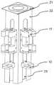
图2为本发明自动注射装置立体视图;2 is a perspective view of the automatic injection device of the present invention;
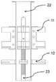
图3为本发明自动注射装置正视图;Fig. 3 is the front view of the automatic injection device of the present invention;
图4a,4b,4c分别为本发明自动注射装置可替换方式的俯视示意图;4a, 4b, and 4c are schematic top views of alternative modes of the automatic injection device of the present invention, respectively;
图5为本发明针组件支撑部可替换方式的立体视图。Figure 5 is a perspective view of an alternative form of the needle assembly support of the present invention.
附图标记说明:Description of reference numbers:
11-针管夹持部,111-固定板,112-持针块,113-夹持槽,12-推杆滑台,21-转盘连接部,22-针组件支撑部,23-推杆滑槽,24-针组件转动滑槽。11-Needle tube clamping part, 111-Fixing plate, 112-Needle holding block, 113-Clamping groove, 12-Push rod sliding table, 21-Turntable connecting part, 22-Needle assembly support part, 23-Push rod sliding groove , 24-pin assembly turning chute.
具体实施方式Detailed ways
结合附图和具体实施例对本发明的技术内容作详细说明。The technical content of the present invention will be described in detail with reference to the accompanying drawings and specific embodiments.
下面将结合实施例对本发明的实施方案进行详细描述,但是本领域技术人员将会理解,下列实施例仅用于说明本发明,而不应视为限制本发明的范围。The embodiments of the present invention will be described in detail below with reference to the examples, but those skilled in the art will understand that the following examples are only used to illustrate the present invention and should not be regarded as limiting the scope of the present invention.
实施例1Example 1
如图2-3所示,本实施例中的自动注射装置具有持针单元、转盘连接单元,其中持针单元包括用于夹持注射器管体的针管夹持部11和位于针管夹持部11下方的推杆滑台12,该推杆滑台12用于移动注射器推杆;转盘连接单元包括用于支撑持针单元的针组件支撑部22,针组件支撑部上端设有转盘连接部21,针组件支撑部22侧壁具有推杆滑槽24,推杆滑台12沿该推杆滑槽23移动。作为优选的方式,针管夹持部11位于所述针组件支撑部的侧壁的推杆滑槽内,并可以在所述推杆滑槽内上下移动。根据不同规格的注射器,可以匹配相适配的的针管夹持部11并将其固定设置在针组件支撑部22的侧壁上。As shown in Figures 2-3, the automatic injection device in this embodiment has a needle holding unit and a turntable connecting unit, wherein the needle holding unit includes a needle
转盘连接单元通过其针组件支撑部22上端的转盘连接部21与注射转台中的上转盘转动连接,并通过外部的控制部控制转盘连接部21带动转盘连接单元相对于上转盘转动。其中,如图1所述,注射转台包括垂直设置的支撑柱,以及位于支撑柱上端的上转盘和位于支撑柱下端的下转盘,所述下转盘在驱动部的驱动下转动并带动支撑柱和上转盘整体转动,所述转盘连接单元沿所述上转盘外周边缘间隔设置。The turntable connection unit is rotatably connected to the upper turntable in the injection turntable through the
其中,本实施例中,转盘连接单元的针组件支撑部22为横截面呈四边形的支撑柱结构,在支撑柱的三个侧壁上分别设有一组持针单元。每组持针单元适配不同型号的注射器,也可以根据实际需要使各组持针单元适配相同型号的注射器。为了提升夹持注射器的稳定性和可靠性,本实施例中优选在针管夹持部11与注射器管体接触表面上设置摩擦力增强结构,该摩擦力增强结构可以为胶垫层、绒垫层等并通过胶粘附在针管夹持部11的夹持表面上,或者直接在针管夹持部11的夹持表面上加工出具有磨砂、凹凸纹路的粗糙结构,从而增加针管与针管夹持部11间的摩擦力,避免针头在移动、注射、拔出等过程中不期望的移动,导致操作的失误。Among them, in this embodiment, the needle
作为本实施例的优选结构,如图2所示,针组件支撑部11具有纵向延伸的固定板111,以及纵向间隔设置于固定板111侧壁上下两端侧的两个持针块112,本实施例中,两个持针块112与固定板111一体成型,而根据实际制造需要,两者也可以通过铆接、焊接等方式固定。每个持针块112朝向远离固定板111的一侧设置用于放入注射器的开口,并且由开口向固定板111一侧向内凹以形成用于夹持注射器的夹持槽113,从而实现将注射器针管卡入夹持槽113并夹持固定的目的。其中,单个针组件支撑部11中的持针块112的夹持槽113具有匹配相同型号针管直径的夹持尺寸,而不同针组件支撑部11可以适配相同或不同尺寸的针管。此外,在夹持槽113内与针管接触的内表面上设置摩擦力增强结构,具体的可以为胶层或磨砂层等增加摩擦力的结构。通过上述结构,相对于现有的注射器固定结构,本发明中的夹持结构一方面,便于取放注射器,在降低与针管的接触面的基础上仍然确保了夹持稳定、不易脱落的技术效果,另一方面,夹持结构更加简单便于制造,在自动注射系统中,占用空间小,更易于安装的提升空间利用效率。As a preferred structure of this embodiment, as shown in FIG. 2 , the needle
实施例2Example 2
如图4a,4b,4c所示,在其他结构不变的前提下,对实施例1中针组件支撑部截面的形状以及持针单元个数进行变换。如图4a针组件支撑部截面为正四边形,各个侧壁均设置有持针单元,针组件支撑部每旋转90°,一个持针单元带动针管加载至待注射工位,通过致动推杆滑台12,移动注射器推杆,从而实现待注射工位上注射器的吸液或注射操作。作为其他的替换方式,如图4b所示,针组件支撑部截面为圆形,持针单元正交分布于针组件支撑部的侧壁上;如图4c所示,针组件支撑部截面为三角形,持针单元正交分布于针组件支撑部各侧壁上。通过旋转针组件支撑部,各持针单元可以分别加载至待注射工位上,从而实现待注射工位上注射器进行吸液或注射操作。As shown in Figures 4a, 4b, and 4c, on the premise that other structures remain unchanged, the shape of the cross-section of the needle assembly support portion and the number of needle holding units in Example 1 are changed. As shown in Figure 4a, the cross-section of the support part of the needle assembly is a regular quadrilateral, and each side wall is provided with a needle holding unit. Every time the support part of the needle assembly rotates by 90°, a needle holding unit drives the needle tube to be loaded to the station to be injected, and the push rod slides by actuating the push rod. The
实施例3Example 3
如图5所示,作为实施例1中针组件支撑部结构的替换方式,本实施例中,在侧壁上开设有周向延伸的针组件转动滑槽24,若干个持针单元通过滑块(图中未示)等连接部件活动卡接在针组件转动滑槽24,并可以沿该针组件转动滑槽24周向转动。本实施例中优选所述针组件转动滑槽24为沿所述针组件支撑部的侧壁开设的闭合环形槽,即每个持针单元均可以沿该针组件转动滑槽24沿单个方向做闭环周向连续转动,而不用改变方向。为了实现自动化控制,通过控制部控制持针单元的转动过程,根据需要将所需的注射器加载至待注射工位上。As shown in FIG. 5 , as an alternative to the structure of the needle assembly support part in Embodiment 1, in this embodiment, a circumferentially extending needle
此外,为了精确控制注射器被加载至准确的位置,在自动注射装置中的持针单元或者所述转盘连接单元中的至少一个上设有位置感测元件,通过与加设在转盘或者装置外框上的监测部件的配合联动,实现对所述持针单元的转动位置的实时监控,并可以对加载过程中存在的任何偏差或失误进行及时校正和/或报警。In addition, in order to precisely control that the syringe is loaded to an accurate position, a position sensing element is provided on at least one of the needle holding unit in the automatic injection device or the connecting unit of the turntable. The cooperation and linkage of the monitoring components on the device can realize real-time monitoring of the rotational position of the needle holding unit, and can timely correct and/or alarm any deviation or error in the loading process.
最后应说明的是:以上各实施例仅用以说明本发明的技术方案,而非对其限制;尽管参照前述各实施例对本发明进行了详细的说明,但本领域的普通技术人员应当理解:其依然可以对前述各实施例所记载的技术方案进行修改,或者对其中部分或者全部技术特征进行等同替换;而这些修改或者替换,并不使相应技术方案的本质脱离本发明各实施例技术方案的范围。Finally, it should be noted that: the above embodiments are only used to illustrate the technical solutions of the present invention, but not to limit it; although the present invention has been described in detail with reference to the foregoing embodiments, those of ordinary skill in the art should understand: It is still possible to modify the technical solutions recorded in the foregoing embodiments, or perform equivalent replacements for some or all of the technical features; and these modifications or replacements do not make the essence of the corresponding technical solutions deviate from the technical solutions of the embodiments of the present invention. range.
Claims (10)
Translated fromChinesePriority Applications (1)
| Application Number | Priority Date | Filing Date | Title |
|---|---|---|---|
| CN202010872467.0ACN111904858A (en) | 2020-08-26 | 2020-08-26 | an automatic injection device |
Applications Claiming Priority (1)
| Application Number | Priority Date | Filing Date | Title |
|---|---|---|---|
| CN202010872467.0ACN111904858A (en) | 2020-08-26 | 2020-08-26 | an automatic injection device |
Publications (1)
| Publication Number | Publication Date |
|---|---|
| CN111904858Atrue CN111904858A (en) | 2020-11-10 |
Family
ID=73278831
Family Applications (1)
| Application Number | Title | Priority Date | Filing Date |
|---|---|---|---|
| CN202010872467.0APendingCN111904858A (en) | 2020-08-26 | 2020-08-26 | an automatic injection device |
Country Status (1)
| Country | Link |
|---|---|
| CN (1) | CN111904858A (en) |
Cited By (2)
| Publication number | Priority date | Publication date | Assignee | Title |
|---|---|---|---|---|
| CN112755331A (en)* | 2020-12-30 | 2021-05-07 | 昀厨智能制造工程(烟台)有限公司 | Automatic injection machine |
| CN113144343A (en)* | 2021-02-04 | 2021-07-23 | 昀厨智能制造工程(烟台)有限公司 | Automatic injection system |
Citations (9)
| Publication number | Priority date | Publication date | Assignee | Title |
|---|---|---|---|---|
| US20120241042A1 (en)* | 2011-03-23 | 2012-09-27 | Saverio Roberto Strangis | Automated syringe filler and loading apparatus |
| CN103007371A (en)* | 2011-09-22 | 2013-04-03 | 深圳市卫邦科技有限公司 | Quantitative suction device for dispensing, and automatic dispensing system applying same |
| CN103565645A (en)* | 2013-11-26 | 2014-02-12 | 威海卫宁医疗科技有限公司 | Injection device for medical drug preparation |
| CN106539687A (en)* | 2016-11-24 | 2017-03-29 | 郑州中拓知识产权代理有限公司 | A kind of nursing section office quick dispenser of liquid |
| CN106584081A (en)* | 2016-12-08 | 2017-04-26 | 达尔嘉(广州)标识设备有限公司 | Accurate assembling machine and method for pre-filling type needle tube push rod |
| CN207203091U (en)* | 2017-03-06 | 2018-04-10 | 山西医科大学 | A kind of radiopharmaceutical configuration device |
| CN108273159A (en)* | 2017-12-30 | 2018-07-13 | 深圳市阿瑟医疗机器人有限公司 | Module for manipulating syringe |
| CN208426534U (en)* | 2017-11-27 | 2019-01-25 | 日照市中医医院 | A kind of anorectum department doctor injection device |
| CN109662893A (en)* | 2018-12-24 | 2019-04-23 | 山西医科大学 | Medicament injection apparatus and dispensing equipment |
- 2020
- 2020-08-26CNCN202010872467.0Apatent/CN111904858A/enactivePending
Patent Citations (9)
| Publication number | Priority date | Publication date | Assignee | Title |
|---|---|---|---|---|
| US20120241042A1 (en)* | 2011-03-23 | 2012-09-27 | Saverio Roberto Strangis | Automated syringe filler and loading apparatus |
| CN103007371A (en)* | 2011-09-22 | 2013-04-03 | 深圳市卫邦科技有限公司 | Quantitative suction device for dispensing, and automatic dispensing system applying same |
| CN103565645A (en)* | 2013-11-26 | 2014-02-12 | 威海卫宁医疗科技有限公司 | Injection device for medical drug preparation |
| CN106539687A (en)* | 2016-11-24 | 2017-03-29 | 郑州中拓知识产权代理有限公司 | A kind of nursing section office quick dispenser of liquid |
| CN106584081A (en)* | 2016-12-08 | 2017-04-26 | 达尔嘉(广州)标识设备有限公司 | Accurate assembling machine and method for pre-filling type needle tube push rod |
| CN207203091U (en)* | 2017-03-06 | 2018-04-10 | 山西医科大学 | A kind of radiopharmaceutical configuration device |
| CN208426534U (en)* | 2017-11-27 | 2019-01-25 | 日照市中医医院 | A kind of anorectum department doctor injection device |
| CN108273159A (en)* | 2017-12-30 | 2018-07-13 | 深圳市阿瑟医疗机器人有限公司 | Module for manipulating syringe |
| CN109662893A (en)* | 2018-12-24 | 2019-04-23 | 山西医科大学 | Medicament injection apparatus and dispensing equipment |
Cited By (2)
| Publication number | Priority date | Publication date | Assignee | Title |
|---|---|---|---|---|
| CN112755331A (en)* | 2020-12-30 | 2021-05-07 | 昀厨智能制造工程(烟台)有限公司 | Automatic injection machine |
| CN113144343A (en)* | 2021-02-04 | 2021-07-23 | 昀厨智能制造工程(烟台)有限公司 | Automatic injection system |
Similar Documents
| Publication | Publication Date | Title |
|---|---|---|
| CN111904858A (en) | an automatic injection device | |
| CN103519831B (en) | Blood collection equipment | |
| JP2006017660A (en) | Radioactivity detection sensor, radioactivity measurement method using this sensor, and radiopharmaceutical automatic administration device | |
| CN106141663A (en) | A kind of transfusion device assembly technology | |
| CN116735902A (en) | Magnetic bead reagent mixing method for immunoanalyzer and immunoanalyzer | |
| CN207123538U (en) | A kind of novel injection pump | |
| CN201845022U (en) | Rotary reagent sampling device | |
| CN221607099U (en) | Automatic loading and unloading structure for blood collection tubes | |
| CN220918940U (en) | Magnetic bead reagent mixing structure, reagent disk and immunoassay instrument | |
| CN111513768A (en) | Endocrinology sampling device | |
| CN201329258Y (en) | Automatic reagent mixing device | |
| CN211463210U (en) | Liquid transfer platform | |
| CN1290758C (en) | Computerized kemote control isotope and reagent automatic filling instrument | |
| CN206738133U (en) | Peristaltic pump and the automatic dispensation apparatus including the peristaltic pump | |
| CN215231045U (en) | Electronic micro pump reversal limiting structure | |
| CN220997880U (en) | Injection taking and placing component and injection taking and placing device | |
| CN222144629U (en) | Disposable urine cup dispenser | |
| CN218165622U (en) | XiLin bottle robot that dispenses | |
| CN111999515A (en) | A medicine bottle automatic loading device | |
| CN219049862U (en) | Propulsion device for preparing Rui Malun injection | |
| CN110498249A (en) | A kind of rotary feed tank and arc rod-type remove separator | |
| CN218824105U (en) | Device for detecting in-vitro adsorption performance of adsorbent | |
| CN217219775U (en) | Electronic injector capable of accurately controlling injection amount | |
| CN221579295U (en) | Anesthesia drug supply device | |
| CN217112367U (en) | Semi-automatic sampling mechanism and blood gas analyzer |
Legal Events
| Date | Code | Title | Description |
|---|---|---|---|
| PB01 | Publication | ||
| PB01 | Publication | ||
| SE01 | Entry into force of request for substantive examination | ||
| SE01 | Entry into force of request for substantive examination | ||
| RJ01 | Rejection of invention patent application after publication | Application publication date:20201110 | |
| RJ01 | Rejection of invention patent application after publication |