CN111904676A - Degradable drug-loaded stent and manufacturing method thereof - Google Patents
Degradable drug-loaded stent and manufacturing method thereofDownload PDFInfo
- Publication number
- CN111904676A CN111904676ACN201910389694.5ACN201910389694ACN111904676ACN 111904676 ACN111904676 ACN 111904676ACN 201910389694 ACN201910389694 ACN 201910389694ACN 111904676 ACN111904676 ACN 111904676A
- Authority
- CN
- China
- Prior art keywords
- drug
- groove
- stent
- loaded
- degradable
- Prior art date
- Legal status (The legal status is an assumption and is not a legal conclusion. Google has not performed a legal analysis and makes no representation as to the accuracy of the status listed.)
- Pending
Links
Images


Classifications
- A—HUMAN NECESSITIES
- A61—MEDICAL OR VETERINARY SCIENCE; HYGIENE
- A61F—FILTERS IMPLANTABLE INTO BLOOD VESSELS; PROSTHESES; DEVICES PROVIDING PATENCY TO, OR PREVENTING COLLAPSING OF, TUBULAR STRUCTURES OF THE BODY, e.g. STENTS; ORTHOPAEDIC, NURSING OR CONTRACEPTIVE DEVICES; FOMENTATION; TREATMENT OR PROTECTION OF EYES OR EARS; BANDAGES, DRESSINGS OR ABSORBENT PADS; FIRST-AID KITS
- A61F2/00—Filters implantable into blood vessels; Prostheses, i.e. artificial substitutes or replacements for parts of the body; Appliances for connecting them with the body; Devices providing patency to, or preventing collapsing of, tubular structures of the body, e.g. stents
- A61F2/82—Devices providing patency to, or preventing collapsing of, tubular structures of the body, e.g. stents
- A61F2/86—Stents in a form characterised by the wire-like elements; Stents in the form characterised by a net-like or mesh-like structure
- A61F2/90—Stents in a form characterised by the wire-like elements; Stents in the form characterised by a net-like or mesh-like structure characterised by a net-like or mesh-like structure
- A61F2/91—Stents in a form characterised by the wire-like elements; Stents in the form characterised by a net-like or mesh-like structure characterised by a net-like or mesh-like structure made from perforated sheets or tubes, e.g. perforated by laser cuts or etched holes
- A61F2/915—Stents in a form characterised by the wire-like elements; Stents in the form characterised by a net-like or mesh-like structure characterised by a net-like or mesh-like structure made from perforated sheets or tubes, e.g. perforated by laser cuts or etched holes with bands having a meander structure, adjacent bands being connected to each other
- A—HUMAN NECESSITIES
- A61—MEDICAL OR VETERINARY SCIENCE; HYGIENE
- A61L—METHODS OR APPARATUS FOR STERILISING MATERIALS OR OBJECTS IN GENERAL; DISINFECTION, STERILISATION OR DEODORISATION OF AIR; CHEMICAL ASPECTS OF BANDAGES, DRESSINGS, ABSORBENT PADS OR SURGICAL ARTICLES; MATERIALS FOR BANDAGES, DRESSINGS, ABSORBENT PADS OR SURGICAL ARTICLES
- A61L31/00—Materials for other surgical articles, e.g. stents, stent-grafts, shunts, surgical drapes, guide wires, materials for adhesion prevention, occluding devices, surgical gloves, tissue fixation devices
- A61L31/14—Materials characterised by their function or physical properties, e.g. injectable or lubricating compositions, shape-memory materials, surface modified materials
- A61L31/16—Biologically active materials, e.g. therapeutic substances
- B—PERFORMING OPERATIONS; TRANSPORTING
- B23—MACHINE TOOLS; METAL-WORKING NOT OTHERWISE PROVIDED FOR
- B23K—SOLDERING OR UNSOLDERING; WELDING; CLADDING OR PLATING BY SOLDERING OR WELDING; CUTTING BY APPLYING HEAT LOCALLY, e.g. FLAME CUTTING; WORKING BY LASER BEAM
- B23K26/00—Working by laser beam, e.g. welding, cutting or boring
- B23K26/36—Removing material
- B23K26/38—Removing material by boring or cutting
- A—HUMAN NECESSITIES
- A61—MEDICAL OR VETERINARY SCIENCE; HYGIENE
- A61F—FILTERS IMPLANTABLE INTO BLOOD VESSELS; PROSTHESES; DEVICES PROVIDING PATENCY TO, OR PREVENTING COLLAPSING OF, TUBULAR STRUCTURES OF THE BODY, e.g. STENTS; ORTHOPAEDIC, NURSING OR CONTRACEPTIVE DEVICES; FOMENTATION; TREATMENT OR PROTECTION OF EYES OR EARS; BANDAGES, DRESSINGS OR ABSORBENT PADS; FIRST-AID KITS
- A61F2/00—Filters implantable into blood vessels; Prostheses, i.e. artificial substitutes or replacements for parts of the body; Appliances for connecting them with the body; Devices providing patency to, or preventing collapsing of, tubular structures of the body, e.g. stents
- A61F2/82—Devices providing patency to, or preventing collapsing of, tubular structures of the body, e.g. stents
- A61F2/86—Stents in a form characterised by the wire-like elements; Stents in the form characterised by a net-like or mesh-like structure
- A61F2/90—Stents in a form characterised by the wire-like elements; Stents in the form characterised by a net-like or mesh-like structure characterised by a net-like or mesh-like structure
- A61F2/91—Stents in a form characterised by the wire-like elements; Stents in the form characterised by a net-like or mesh-like structure characterised by a net-like or mesh-like structure made from perforated sheets or tubes, e.g. perforated by laser cuts or etched holes
- A61F2/915—Stents in a form characterised by the wire-like elements; Stents in the form characterised by a net-like or mesh-like structure characterised by a net-like or mesh-like structure made from perforated sheets or tubes, e.g. perforated by laser cuts or etched holes with bands having a meander structure, adjacent bands being connected to each other
- A61F2002/91533—Stents in a form characterised by the wire-like elements; Stents in the form characterised by a net-like or mesh-like structure characterised by a net-like or mesh-like structure made from perforated sheets or tubes, e.g. perforated by laser cuts or etched holes with bands having a meander structure, adjacent bands being connected to each other characterised by the phase between adjacent bands
- A—HUMAN NECESSITIES
- A61—MEDICAL OR VETERINARY SCIENCE; HYGIENE
- A61F—FILTERS IMPLANTABLE INTO BLOOD VESSELS; PROSTHESES; DEVICES PROVIDING PATENCY TO, OR PREVENTING COLLAPSING OF, TUBULAR STRUCTURES OF THE BODY, e.g. STENTS; ORTHOPAEDIC, NURSING OR CONTRACEPTIVE DEVICES; FOMENTATION; TREATMENT OR PROTECTION OF EYES OR EARS; BANDAGES, DRESSINGS OR ABSORBENT PADS; FIRST-AID KITS
- A61F2/00—Filters implantable into blood vessels; Prostheses, i.e. artificial substitutes or replacements for parts of the body; Appliances for connecting them with the body; Devices providing patency to, or preventing collapsing of, tubular structures of the body, e.g. stents
- A61F2/82—Devices providing patency to, or preventing collapsing of, tubular structures of the body, e.g. stents
- A61F2/86—Stents in a form characterised by the wire-like elements; Stents in the form characterised by a net-like or mesh-like structure
- A61F2/90—Stents in a form characterised by the wire-like elements; Stents in the form characterised by a net-like or mesh-like structure characterised by a net-like or mesh-like structure
- A61F2/91—Stents in a form characterised by the wire-like elements; Stents in the form characterised by a net-like or mesh-like structure characterised by a net-like or mesh-like structure made from perforated sheets or tubes, e.g. perforated by laser cuts or etched holes
- A61F2/915—Stents in a form characterised by the wire-like elements; Stents in the form characterised by a net-like or mesh-like structure characterised by a net-like or mesh-like structure made from perforated sheets or tubes, e.g. perforated by laser cuts or etched holes with bands having a meander structure, adjacent bands being connected to each other
- A61F2002/9155—Adjacent bands being connected to each other
- A61F2002/91558—Adjacent bands being connected to each other connected peak to peak
- A—HUMAN NECESSITIES
- A61—MEDICAL OR VETERINARY SCIENCE; HYGIENE
- A61F—FILTERS IMPLANTABLE INTO BLOOD VESSELS; PROSTHESES; DEVICES PROVIDING PATENCY TO, OR PREVENTING COLLAPSING OF, TUBULAR STRUCTURES OF THE BODY, e.g. STENTS; ORTHOPAEDIC, NURSING OR CONTRACEPTIVE DEVICES; FOMENTATION; TREATMENT OR PROTECTION OF EYES OR EARS; BANDAGES, DRESSINGS OR ABSORBENT PADS; FIRST-AID KITS
- A61F2210/00—Particular material properties of prostheses classified in groups A61F2/00 - A61F2/26 or A61F2/82 or A61F9/00 or A61F11/00 or subgroups thereof
- A61F2210/0004—Particular material properties of prostheses classified in groups A61F2/00 - A61F2/26 or A61F2/82 or A61F9/00 or A61F11/00 or subgroups thereof bioabsorbable
- A—HUMAN NECESSITIES
- A61—MEDICAL OR VETERINARY SCIENCE; HYGIENE
- A61F—FILTERS IMPLANTABLE INTO BLOOD VESSELS; PROSTHESES; DEVICES PROVIDING PATENCY TO, OR PREVENTING COLLAPSING OF, TUBULAR STRUCTURES OF THE BODY, e.g. STENTS; ORTHOPAEDIC, NURSING OR CONTRACEPTIVE DEVICES; FOMENTATION; TREATMENT OR PROTECTION OF EYES OR EARS; BANDAGES, DRESSINGS OR ABSORBENT PADS; FIRST-AID KITS
- A61F2240/00—Manufacturing or designing of prostheses classified in groups A61F2/00 - A61F2/26 or A61F2/82 or A61F9/00 or A61F11/00 or subgroups thereof
- A61F2240/001—Designing or manufacturing processes
- A—HUMAN NECESSITIES
- A61—MEDICAL OR VETERINARY SCIENCE; HYGIENE
- A61F—FILTERS IMPLANTABLE INTO BLOOD VESSELS; PROSTHESES; DEVICES PROVIDING PATENCY TO, OR PREVENTING COLLAPSING OF, TUBULAR STRUCTURES OF THE BODY, e.g. STENTS; ORTHOPAEDIC, NURSING OR CONTRACEPTIVE DEVICES; FOMENTATION; TREATMENT OR PROTECTION OF EYES OR EARS; BANDAGES, DRESSINGS OR ABSORBENT PADS; FIRST-AID KITS
- A61F2250/00—Special features of prostheses classified in groups A61F2/00 - A61F2/26 or A61F2/82 or A61F9/00 or A61F11/00 or subgroups thereof
- A61F2250/0058—Additional features; Implant or prostheses properties not otherwise provided for
- A61F2250/0067—Means for introducing or releasing pharmaceutical products into the body
- A61F2250/0068—Means for introducing or releasing pharmaceutical products into the body the pharmaceutical product being in a reservoir
Landscapes
- Health & Medical Sciences (AREA)
- Engineering & Computer Science (AREA)
- Biomedical Technology (AREA)
- Optics & Photonics (AREA)
- Physics & Mathematics (AREA)
- Life Sciences & Earth Sciences (AREA)
- General Health & Medical Sciences (AREA)
- Veterinary Medicine (AREA)
- Public Health (AREA)
- Heart & Thoracic Surgery (AREA)
- Vascular Medicine (AREA)
- Animal Behavior & Ethology (AREA)
- Oral & Maxillofacial Surgery (AREA)
- Transplantation (AREA)
- Cardiology (AREA)
- Plasma & Fusion (AREA)
- Mechanical Engineering (AREA)
- Chemical & Material Sciences (AREA)
- Medicinal Chemistry (AREA)
- Molecular Biology (AREA)
- Surgery (AREA)
- Epidemiology (AREA)
- Media Introduction/Drainage Providing Device (AREA)
- Materials For Medical Uses (AREA)
Abstract
Translated fromChinese
Description
Translated fromChinese技术领域technical field
本发明涉及医疗器械技术领域,特别是涉及一种可降解载药支架及其制作方法。The invention relates to the technical field of medical devices, in particular to a degradable drug-carrying stent and a manufacturing method thereof.
背景技术Background technique
心血管疾病已成为威胁人类健康的主要疾病之一。心血管疾病中最常见的一种疾病——冠状动脉性心脏病简称冠心病,指由于脂质代谢不正常,血液中的脂质沉着在原本光滑的动脉内膜上,形成类似粥样的白色斑块,称为动脉粥样硬化病变。经皮动脉介入支架手术已然成为重要的治疗手段。支架的发展阶段为金属裸支架、药物洗脱支架。金属裸支架存在的最大问题是发生内膜增生而导致再狭窄。药物洗脱支架的应用使再狭窄率由裸支架的30%下降到10%以下。Cardiovascular disease has become one of the major diseases that threaten human health. One of the most common diseases in cardiovascular disease - coronary heart disease is referred to as coronary heart disease. Plaques, called atherosclerotic lesions. Percutaneous arterial stenting has become an important treatment method. The development stages of stents are bare metal stents and drug-eluting stents. The biggest problem with bare metal stents is restenosis caused by intimal hyperplasia. The application of drug-eluting stents reduces the restenosis rate from 30% of bare stents to less than 10%.
随着支架材料技术的发展,可降解支架以其优越的降解性得到广泛的应用,能够在植入体内一段时期后被降解吸收。With the development of stent material technology, degradable stents have been widely used due to their superior degradability, which can be degraded and absorbed after being implanted in the body for a period of time.
然而,可降解支架依然存在一些问题。例如,药物涂覆在支架表面上,容易出现溢出以及分布不均的现象,在植入体内后,药物释放不均匀或出现溢出脱落,容易引起血栓。此外,可降解支架所采用的材料相比金属支架而言较为脆弱。基于此,业界急需攻克如何在提供足够的支撑力的情况下改善药物在支架上的附着能力这一现实性技术难题。However, there are still some problems with degradable stents. For example, if the drug is coated on the surface of the stent, it is prone to overflow and uneven distribution. After implantation in the body, the drug is released unevenly or overflows and falls off, which is likely to cause thrombosis. In addition, the materials used in degradable stents are fragile compared to metal stents. Based on this, the industry urgently needs to overcome the practical technical problem of how to improve the adhesion of drugs on stents while providing sufficient supporting force.
发明内容SUMMARY OF THE INVENTION
基于此,本发明提供一种可降解载药支架以及该可降解载药支架的制作方法,在提供足够的支撑力的情况下改善药物在可降解支架上的附着能力。Based on this, the present invention provides a degradable drug-loaded stent and a manufacturing method of the degradable drug-loaded stent, which can improve the adhesion ability of drugs on the degradable stent under the condition of providing sufficient supporting force.
一种可降解载药支架,所述可降解载药支架包括生物可降解聚合物制成的支架主体,所述支架主体为径向可扩展的网柱状结构,具有收缩状态及扩张状态,所述网柱状结构的外表面开设有载药槽,所述载药槽能够随所述支架主体在收缩状态及扩张状态之间变化,所述载药槽的深度为所述网柱状结构的壁厚的10%~60%。A degradable drug-loaded stent, the degradable drug-loaded stent comprises a stent body made of a biodegradable polymer, the stent body is a radially expandable mesh column structure, and has a contracted state and an expanded state, and the The outer surface of the net columnar structure is provided with a drug-carrying groove, the drug-carrying groove can change between the contracted state and the expanded state with the stent body, and the depth of the drug-carrying groove is equal to the wall thickness of the net columnar structure. 10% to 60%.
在其中一个实施例中,所述载药槽的深度为所述网柱状结构的壁厚的25%~45%。In one embodiment, the depth of the drug-carrying groove is 25% to 45% of the wall thickness of the net columnar structure.
在其中一个实施例中,所述载药槽的深度与宽度满足如下条件:Y=120-2X;In one embodiment, the depth and width of the drug-carrying groove satisfy the following conditions: Y=120-2X;
其中,Y为槽深,X为槽宽;Y的取值范围为小于等于80微米。Among them, Y is the groove depth, X is the groove width; the value range of Y is less than or equal to 80 microns.
在其中一个实施例中,所述生物可降解聚合物包括下述一种或多种物质:聚乳酸(PLA)、聚左旋乳酸(PLLA)、聚乙交酯或聚羟基乙酸,PGA、聚氰基丙烯酸酯(PACA),聚己酸内酯(PCL)、聚酸酐类、聚乳酸共聚物(PLGA)、聚羟基丁酸戊酯(PHBV)、聚乙酰谷氨酸(PAGA)、聚正酯(POE)、聚氧化乙烯/聚丁烯共聚物(PEO/PBTP),聚原酸酯、聚己内酯、聚羟基乙酸、聚氧化乙烯/聚对苯二甲酸丁二酯共聚物、异丁烯酸盐或酯、甲基丙烯酸盐或酯、聚亚安酯、硅树脂、聚乙烯乙醇、乙烯基乙醇、聚羟基乙酸、聚磷酸酯酶,以及上述聚合物之间的共聚物或共混物。In one embodiment, the biodegradable polymer comprises one or more of the following: polylactic acid (PLA), poly-L-lactic acid (PLLA), polyglycolide or polyglycolic acid, PGA, polycyanide Acrylate (PACA), polycaprolactone (PCL), polyanhydrides, polylactic acid copolymer (PLGA), polyamyl hydroxybutyrate (PHBV), polyacetylglutamic acid (PAGA), polyorthoester (POE), polyethylene oxide/polybutylene copolymer (PEO/PBTP), polyorthoester, polycaprolactone, polyglycolic acid, polyethylene oxide/polybutylene terephthalate copolymer, methacrylate Salts or esters, methacrylates or esters, polyurethanes, silicones, polyvinyl alcohol, vinyl alcohol, polyglycolic acid, polyphosphatase, and copolymers or blends between the foregoing polymers.
在其中一个实施例中,所述支架主体包括多个支撑单元环和连接杆,所述支撑单元环之间通过所述连接杆相连,以形成所述网柱状结构,所述载药槽位于所述支撑单元环上。In one embodiment, the stent body includes a plurality of supporting unit rings and connecting rods, the supporting unit rings are connected by the connecting rods to form the net column structure, and the drug-carrying groove is located in the on the support unit ring.
在其中一个实施例中,所述载药槽的累计槽长为其所在的所述支撑单元环的长度的0.9倍~5倍。In one embodiment, the cumulative groove length of the drug-carrying groove is 0.9 times to 5 times the length of the supporting unit ring where it is located.
在其中一个实施例中,每一所述支撑单元环上的载药槽为连续槽,在所述支撑单元环上形成两端部。In one embodiment, the drug-carrying groove on each of the supporting unit rings is a continuous groove, and both ends are formed on the supporting unit ring.
在其中一个实施例中,每一所述支撑单元环上开设有多个所述载药槽,多个所述载药槽沿所述支撑单元环的支杆延伸方向布置且互不相交。In one embodiment, each of the supporting unit rings is provided with a plurality of the drug-carrying grooves, and the plurality of the drug-carrying grooves are arranged along the extending direction of the struts of the supporting unit ring and do not intersect with each other.
在其中一个实施例中,所述载药槽的槽线为沿所述支撑单元环周向延伸的曲线或波浪线。In one embodiment, the groove line of the drug-carrying groove is a curved line or a wave line extending along the circumferential direction of the support unit ring.
另一方面,本发明还提供了一种可降解载药支架的制作方法,所述可降解载药支架的制作方法包括以下步骤:On the other hand, the present invention also provides a method for making a degradable drug-loaded stent, and the method for making the degradable drug-loaded stent includes the following steps:
采用生物可降解聚合物加工成型管材或支架型坯;Use biodegradable polymers to process tube or stent parisons;
利用飞秒激光器对成型管材或支架型坯进行加工,以形成支架主体,所述支架主体为径向可扩展的网柱状结构;Process the formed tube or the stent parison with a femtosecond laser to form a stent body, the stent body being a radially expandable mesh column structure;
利用飞秒激光器在所述网柱状结构的外表面开设载药槽,所述载药槽的深度为所述网柱状结构的壁厚的10%~60%。Using a femtosecond laser, a drug-carrying groove is formed on the outer surface of the net columnar structure, and the depth of the drug-carrying groove is 10% to 60% of the wall thickness of the net columnar structure.
在其中一个实施例中,飞秒激光器开设载药槽时,飞秒激光器的聚焦点在网柱状结构的外表面移动速度S满足如下条件:In one embodiment, when the femtosecond laser opens the drug-loading groove, the moving speed S of the focal point of the femtosecond laser on the outer surface of the net columnar structure satisfies the following conditions:
V<S≤10VV<S≤10V
其中,V为飞秒激光器对成型管材或支架型坯进行加工时,飞秒激光器的聚焦点相对成型管材或支架型坯的移动速度。Among them, V is the moving speed of the focal point of the femtosecond laser relative to the forming pipe or the bracket parison when the femtosecond laser is processing the formed pipe or the bracket parison.
本发明提供了可降解载药支架及其制作方法,可降解载药支架的支架主体采用生物可降解聚合物制成,以实现载料支架的生物降解,同时,通过开设载药槽改善支架附着能力,且将载药槽的深度控制在网柱状结构的壁厚的10%~60%,以在满足可降解载药支架的物理性能要求的同时为药物提供较好的附着效果。The invention provides a degradable drug-loaded stent and a manufacturing method thereof. The stent body of the degradable drug-loaded stent is made of a biodegradable polymer, so as to realize the biodegradation of the drug-loaded stent, and meanwhile, the stent attachment is improved by opening a drug-loading groove. and the depth of the drug-carrying groove is controlled at 10% to 60% of the wall thickness of the net-column structure, so as to meet the physical performance requirements of the degradable drug-carrying stent and provide a better adhesion effect for the drug.
附图说明Description of drawings
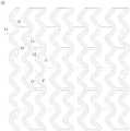
图1为一实施方式中可降解载药支架的支架主体结构示意图;FIG. 1 is a schematic diagram of a stent main body structure of a degradable drug-loaded stent in one embodiment;
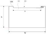
图2为图1示出的可降解载药支架的支架主体沿轴向的正视示意图;FIG. 2 is a schematic front view of the stent body of the degradable drug-loaded stent shown in FIG. 1 along the axial direction;
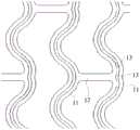
图3为图1示出的可降解载药支架的支架主体的展开示意图;FIG. 3 is a schematic view of the unfolding of the stent body of the degradable drug-loaded stent shown in FIG. 1;
图4为图3示出的可降解载药支架的支架主体的局部结构示意图;Fig. 4 is a partial structural schematic diagram of the stent body of the degradable drug-loaded stent shown in Fig. 3;
图5为图4示出的可降解载药支架的支架主体沿I-I线的剖视示意图;5 is a schematic cross-sectional view of the stent body of the degradable drug-loaded stent shown in FIG. 4 along line I-I;
图6为图4示出的可降解载药支架的支架主体沿I-I线进行剖视时,另一实施方式的剖视示意图;6 is a cross-sectional schematic diagram of another embodiment when the stent body of the degradable drug-loaded stent shown in FIG. 4 is cross-sectionally taken along the line I-I;
图7为图4示出的可降解载药支架的支架主体沿I-I线进行剖视时,又一实施方式的剖视示意图;7 is a schematic cross-sectional view of another embodiment when the stent body of the degradable drug-loaded stent shown in FIG. 4 is cross-sectionally taken along the line I-I;
图8为图4示出的可降解载药支架的支架主体沿I-I线进行剖视时,再一实施方式的剖视示意图;FIG. 8 is a cross-sectional schematic diagram of still another embodiment when the stent body of the degradable drug-loaded stent shown in FIG. 4 is cut along the I-I line;
图9为另一实施方式的可降解载药支架的支架主体展开时的局部结构示意图;FIG. 9 is a schematic partial structure diagram of the stent body of the degradable drug-loaded stent according to another embodiment when it is deployed;
图10为图9中圆圈F部分的局部放大示意图;Fig. 10 is the partial enlarged schematic diagram of the circle F part in Fig. 9;
图11为另一实施方式的可降解载药支架的支架主体展开时的局部结构示意图;FIG. 11 is a schematic partial structure diagram of the stent body of the degradable drug-loaded stent according to another embodiment when it is deployed;
图12为另一实施方式的可降解载药支架中,支架主体的支撑单元环上的载药槽形态示意图;12 is a schematic diagram of the shape of the drug-loading groove on the support unit ring of the stent body in the degradable drug-loaded stent according to another embodiment;
图13为另一实施方式的可降解载药支架的支架主体展开时的局部结构示意图;FIG. 13 is a schematic partial structure diagram of the stent body of the degradable drug-loaded stent according to another embodiment when it is deployed;
图14为图13中虚线框处的局部放大示意图;Fig. 14 is a partial enlarged schematic diagram at the dotted frame in Fig. 13;
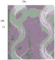
图15为一实施方式中的可降解载药支架中,支架主体的支撑单元环上开设连续的载药槽时,外表面一侧的电子显微示意图;15 is an electron microscope schematic diagram of the outer surface side of the degradable drug-loaded stent in one embodiment, when a continuous drug-loading groove is formed on the support unit ring of the stent body;
图16为图15示出的支架主体的支撑单元环上开设连续的载药槽时,内表面一侧的电子显微示意图;Figure 16 is a schematic view of an electron microscope on the inner surface side when a continuous drug-carrying groove is opened on the support unit ring of the stent body shown in Figure 15;
图17为一实施方式的支架主体的支撑单元环上开设的载药槽的电子显微示意图,图中示出,载药槽的端部处比连续加工的非端部处深;17 is a schematic view of an electron micrograph of a drug-carrying groove opened on the support unit ring of the stent main body according to an embodiment, the figure shows that the end of the drug-carrying groove is deeper than the non-end part of the continuous processing;
图18为支架主体的支撑单元环上开设的载药槽时,载药槽的端部处击穿内表面时电子显微示意图;18 is a schematic view of an electron microscope when the end of the drug-carrying groove penetrates the inner surface when the drug-carrying groove is opened on the support unit ring of the stent main body;
图19为一实施方式的可降解载药支架的制作方法的步骤流程示意图。FIG. 19 is a schematic flow chart of steps of a method for fabricating a degradable drug-loaded stent according to an embodiment.
具体实施方式Detailed ways
为了便于理解本发明,下面将参照相关附图对本发明进行更全面的描述。附图中给出了本发明的较佳实施方式。但是,本发明可以以许多不同的形式来实现,并不限于本文所描述的实施方式。相反地,提供这些实施方式的目的是使对本发明的公开内容理解的更加透彻全面。In order to facilitate understanding of the present invention, the present invention will be described more fully hereinafter with reference to the related drawings. The preferred embodiments of the invention are shown in the accompanying drawings. However, the present invention may be embodied in many different forms and is not limited to the embodiments described herein. Rather, these embodiments are provided so that a thorough and complete understanding of the present disclosure is provided.
需要说明的是,当元件被称为“固定于”另一个元件,它可以直接在另一个元件上或者也可以存在居中的元件。当一个元件被认为是“连接”另一个元件,它可以是直接连接到另一个元件或者可能同时存在居中元件,所述“连接”也包括可拆卸的连接。本文所使用的术语“内”、“外”、“左”、“右”以及类似的表述只是为了说明的目的,并不表示是唯一的实施方式。It should be noted that when an element is referred to as being "fixed to" another element, it can be directly on the other element or intervening elements may also be present. When an element is considered to be "connected" to another element, whether it is directly connected to the other element or intervening elements may also be present, the "connection" also includes detachable connections. The terms "inner", "outer", "left", "right" and similar expressions used herein are for the purpose of illustration only and do not represent the only embodiment.
结合图1和图2所示,一实施例中的一种可降解载药支架,包括生物可降解聚合物制成的支架主体10,支架主体10采用生物可降解聚合物制成,在放入体内后,可以被降解吸收,避免传统的金属支架需要通过二次手术取出而引起负面效果。该实施例中,支架主体10为径向可扩展的网柱状结构,具有收缩状态及扩张状态。网柱状结构具有相对的内表面10a和外表面10b,其中,网柱状结构的外表面10b开设有载药槽13,载药槽13的深度为网柱状结构的壁厚的10%~60%。如图2所示,网柱状结构的壁厚h即为内表面10a与外表面10b之间的距离。1 and 2, a degradable drug-loaded stent in one embodiment includes a
该实施方式中,在网柱状结构的外表面10b开设载药槽13,能够改善药物在可降解载药支架上的附着能力,从而降低药物脱落机率。当载药槽13的深度为网柱状结构的壁厚的10%~60%时,可降解载药支架也能够满足一定的物理性能要求,例如,径向抗挤压性能、过渡扩张性能或轴向回缩能力需要满足相应的医疗器械标准。如果载药槽13的深度占网柱状结构的壁厚较多,将会导致可降解载药支架变薄而容易出现断裂。通过对载药槽13的深度进行合理设置既能够满足物理性能要求,提供足够支撑力,又能够为药物提供较好的附着效果。In this embodiment, the drug-carrying
在一些实施方式中,利用图1示出的可降解载药支架进行物理性能测试时,所采用的可降解载药支架的结构设计、尺寸都一致,只是载药槽13的深度有所变化。具体地,参照表1所示:In some embodiments, when using the degradable drug-loaded stent shown in FIG. 1 to perform a physical property test, the structure design and size of the degradable drug-loaded stent used are the same, but the depth of the drug-loaded
表1Table 1

表1中,网柱状结构的厚度均为125um,仅调整载药槽13的深度,使得相应的槽深占比分别为31.07%、36.21%、60.02%和67.64%。其中,槽深占比指的是载药槽13的深度为网柱状结构的壁厚h的比例。分别对槽深占比为31.07%、36.21%、60.02%和67.64%的可降解载药支架进行支撑力及过扩测试,通过多次测试并求得相应均值,发现槽深占比为31.07%、36.21%、60.02%的可降解载药支架的支撑力均值均不低于50Kpa,符合可降解载药支架类医疗器械在体内支撑的标准。相应地,槽深占比为67.64%的可降解载药支架所测得的支撑力均值为49.6Kpa,略小于规定的50Kpa,由于支撑力不够而存在体内坍缩风险,被认定为不合格。表1还表明,槽深占比在31.07%、36.21%、60.02%和67.64%变化时,相应的可降解载药支架的过扩均值变化很小,且都在4.5mm以上,符合可降解载药支架的扩张性能标准。In Table 1, the thickness of the net columnar structure is all 125um, and only the depth of the drug-carrying
需要说明的是,表1仅从槽深占比分别为31.07%、36.21%、60.02%和67.64%的可降解载药支架对支撑力及过扩性能进行测试,并反应出槽深占比对可降解载药支架的支撑力影响较大,而对过扩性能影响较小。但在维持载药槽13的载药量不变,即载药槽13的容积不变的情况下,载药槽13的深度改变需要载药槽13的槽宽适应性的改变,确切的说,载药槽13相对网柱状结构的槽深占比越大,表明载药槽13的越深,继而此时需要扩宽载药槽13的槽宽或者提高开槽面积占据网柱状结构的外表面10b的面积比。也就是说,在维持载药槽13对药物的良好附着效果的情况下,槽深占比不可能无限的小,过小便会导致开槽面积占据网柱状结构的外表面10b的面积比过大,容易导致载药槽的边缘结构较薄而强度较低,进而容易出现裂纹。It should be noted that Table 1 only tests the support force and overexpansion performance from the degradable drug-loaded stents with groove depths of 31.07%, 36.21%, 60.02%, and 67.64%, respectively, and reflects the ratio of groove depth to The support force of the degradable drug-loaded stent has a greater impact, while the overexpansion performance is less affected. However, under the condition that the drug loading amount of the drug-carrying
发明人在减小槽深占比的研究过程中发现,当槽深占比减小到低于10%时,为了确保足够的载药空间而扩宽槽的宽度,导致载药槽的边缘结构变薄而在进行扩张测试时出现裂纹,此时,可降解载药支架的整体力学性能下降。基于此,在考虑可降解载药支架提供足够的支撑力以及药物在支架上的附着能力的情况下,将载药槽13的深度控制在占网柱状结构的壁厚的10%~60%是合理安全的。During the research process of reducing the proportion of the groove depth, the inventor found that when the proportion of the groove depth was reduced to less than 10%, the width of the groove was widened in order to ensure sufficient drug-carrying space, resulting in the edge structure of the drug-carrying groove. Thinning and cracks appear during the expansion test, at this time, the overall mechanical properties of the degradable drug-loaded stent decrease. Based on this, considering the sufficient supporting force provided by the degradable drug-loaded stent and the adhesion of the drug on the stent, the depth of the drug-
在一些实施方式中,可以将载药槽13的深度控制在占网柱状结构的壁厚h的25%~45%,维持同等载药量的情况下,这一范围所对应的载药槽13的深度和宽度能够更好的适应加工需要。例如,采取飞秒激光器发出的激光束在网柱状结构的外表面10b加工载药槽13时,激光束单次扫描的加工宽度为φ,那么将载药槽13的宽度大致控制在φ时,便避免激光重复加工。此时,只需要激光束沿着加工路径移动便可以形成与加工路径延伸方向相适应的载药槽13。In some embodiments, the depth of the drug-carrying
在一些实施方式中,为了满足载药量的要求,载药槽的深度与宽度满足如下条件:Y=120-2X;其中,Y为槽深,X为槽宽;Y的取值范围为小于等于80微米。当槽深与槽宽满足上述条件时,既可以避免槽深过大影响生物可降解聚合物支架的力学性能,也可以满足医用支架的载药需求。In some embodiments, in order to meet the requirements of drug loading, the depth and width of the drug-carrying groove meet the following conditions: Y=120-2X; wherein, Y is the depth of the groove, and X is the width of the groove; the value range of Y is less than is equal to 80 microns. When the groove depth and the groove width satisfy the above conditions, it can not only avoid that the groove depth is too large to affect the mechanical properties of the biodegradable polymer stent, but also can meet the drug-carrying requirements of the medical stent.
支架主体10所采用的生物可降解聚合物可以有多种选择。The biodegradable polymer used for the
在一些实施方式中,生物可降解聚合物包括下述一种或多种物质:聚乳酸(PLA)、聚左旋乳酸(PLLA)、聚乙交酯或聚羟基乙酸,PGA、聚氰基丙烯酸酯(PACA),聚己酸内酯(PCL)、聚酸酐类、聚乳酸共聚物(PLGA)、聚羟基丁酸戊酯(PHBV)、聚乙酰谷氨酸(PAGA)、聚正酯(POE)、聚氧化乙烯/聚丁烯共聚物(PEO/PBTP),聚原酸酯、聚己内酯、聚羟基乙酸、聚氧化乙烯/聚对苯二甲酸丁二酯共聚物、异丁烯酸盐或酯、甲基丙烯酸盐或酯、聚亚安酯、硅树脂、聚乙烯乙醇、乙烯基乙醇、聚羟基乙酸、聚磷酸酯酶,以及上述聚合物的单体中的至少两种形成的共聚物或共混物。In some embodiments, the biodegradable polymer includes one or more of the following: polylactic acid (PLA), poly-L-lactic acid (PLLA), polyglycolide or polyglycolic acid, PGA, polycyanoacrylate (PACA), polycaprolactone (PCL), polyanhydrides, polylactic acid copolymer (PLGA), polyamyl hydroxybutyrate (PHBV), polyacetylglutamic acid (PAGA), polyorthoester (POE) , polyethylene oxide/polybutylene copolymer (PEO/PBTP), polyorthoester, polycaprolactone, polyglycolic acid, polyethylene oxide/polybutylene terephthalate copolymer, methacrylate or ester , methacrylates or esters, polyurethanes, silicone resins, polyvinyl alcohol, vinyl alcohol, polyglycolic acid, polyphosphatase, and copolymers formed from at least two of the monomers of the above polymers or blend.
在一些实施方式中,载药槽13中所填充的药物包括下述一种或多种物质:抗炎症类药物、抗血小板药物、抗凝血剂、抗癌药物、免疫抑制剂和/或激素、内膜细胞增生抑制剂,优选为雷帕霉素及其衍生物、紫杉醇及其衍生物、普罗布考及其衍生物、地塞米松及其衍生物、积雪草苷、肝素、阿司匹林、西洛他唑、噻氯匹定、雷公藤内酯、环孢霉素、他克莫斯或雌二醇的一种或多种,更优选为雷帕霉素。In some embodiments, the drugs filled in the
继续参阅图1所示,支架主体10包括多个支撑单元环11和连接杆12,支撑单元环11之间通过连接杆12相连,以形成网柱状结构,载药槽13位于支撑单元环11上。Continuing to refer to FIG. 1 , the stent
结合图3和图4所示,每一支撑单元环11上的载药槽13为连续槽,在支撑单元环11上形成两端部。连续槽可以理解为载药槽13在卡槽过程中没有中断,也就是只有加工的起点位置和终点位置。以激光加工为例,在加工载药槽13时,激光器持续出光,激光的聚焦点从开槽的起点位置移至终点位置,这样便可以在同等槽长的情况下,尽可能的减少载药槽13在支撑单元环11上留下的端部,也即减少了端部激光能量集中而出现材料击穿。这种结构形式下,既能够提供较多载药量,又能够减少击穿以防止支架主体10材料缺失而产生局部应力,降低支架主体10断裂风险。As shown in FIG. 3 and FIG. 4 , the drug-carrying
在一些实施方式中,载药槽13的两端部重合以使得载药槽13的槽线闭合。该实施方式中,载药槽13为连续槽,从而尽可能减少载药槽13在支撑单元环11上的停顿位置,即端部。由于采用激光加工载药槽13时,激光能量容易在端部位置产生叠加效应而击穿生物可降解聚合物制成的支架主体10,因此通过这种连续开槽的方式,减少支架主体10的击穿,尽可能减少支架主体10应力点的数量,以保持可降解载药支架良好的物理性能。In some embodiments, the two ends of the drug-carrying
结合图15和图16所示,载药槽13的连续性,使得内表面10a所在一侧不会出现击穿点。结合图17和图18所示,在载药槽13的端部13c处,受激光能量叠加的影响,端部13c处的深度比连续加工的非端部处深,容易产生端部13c处击穿现象(参阅图18所示),在内表面10a所在一侧形成击穿点,此处形成局部的材料应力,不利于支架主体10的结构强度。从而通过上述实施方式,利用激光持续开槽,形成槽线连续的载药槽13可以减少这种端部击穿现象,以保持可降解载药支架良好的物料性能。As shown in FIG. 15 and FIG. 16 , the continuity of the drug-carrying
在一些实施方式中,载药槽13的两端部间隔设置,从而进一步避免利用激光加工载药槽13时,激光能量在两端部叠加而容易穿透支撑单元环11。通过这种结构形式,减少支撑单元环11被穿透的风险,从而避免支架主体10在收缩或扩张时,被穿透的位置产生应力集中而发生断裂。In some embodiments, the two ends of the drug-carrying
在一些实施方式中,每一支撑单元环11上开设有多个载药槽13,以提高载药量。In some embodiments, each
需要说明的是,支撑单元环11结构形态具有多种可能,例如,在一些实施方式中,支撑单元环11可以是由一个支杆形成的环状结构。再如,在一些实施方式中,支撑单元环11可以是多个支杆形成的网环状结构。对于支撑单元环的结构形态,在此不作限定。It should be noted that the structure of the
此外,在支撑单元环11的表面进行开设载药槽13时,载药槽13的延伸方向以及布置形式可以适应构成支撑单元环11的支杆作适应性调整。例如,在一些实施方式中,支撑单元环11由支杆构成,在设置多个载药槽13时,多个载药槽13沿支撑单元环11的支杆延伸方向布置,且多个载药槽13互不相交,从而避免相交的地方出现激光能量叠加而导致支架主体10容易产生击穿。结合图11所示,每一支撑单元环11上开设有2个载药槽13,2个载药槽13在延伸方向上的每一处轮廓相同,即2个载药槽13在延伸方向上的每处间隔相等,进而使得2个载药槽13在支撑单元环11的表面呈均匀分布,支撑单元环11各处的材料物理性能相当,受力较为均衡,整体结构强度较好。In addition, when the drug-carrying
在此基础上,在支撑单元环11为多个支杆构成时,多个支杆上开设的载药槽13除了采用连续开槽且不相交的形式来获得可降解载药支架整体上较佳的物理力学性能,还可以根据各支杆的延伸方向进行开槽,确切的说,各支杆上的载药槽13的槽线的走向与支杆的走向形态一致,从而使得支杆在开槽后,各处的受力相当,避免了产生局部应力而容易断裂。On this basis, when the
结合图12所示,在一些实施方式中,载药槽13的槽线还可以是沿支撑单元环11周向延伸的曲线或波浪线,以提高在沿支撑单元环11延伸方向上的单位长度上的累计槽长,进而提高载药量。12 , in some embodiments, the groove line of the drug-carrying
载药槽13的截面形状可以具有多种可能。例如,如图5所示,载药槽13的截面形状为V形。如图6所示,载药槽13的截面形状为U形。再如图7和图8所示,载药槽13的截面形状为梯形。结合图5至图8所示,载药槽13的深度d以及宽度a可以适应性调整,以满足不同载药量需求,只需满足载药槽13的深度d为网柱状结构的壁厚h的10%~60%即可。The cross-sectional shape of the drug-carrying
在一些实施方式中,载药槽13的宽度a为支撑单元环11的宽度W的10%~80%。在维持载药量不变的情况下,载药槽13的宽度a越大,载药槽13的深度d越小,也就是说,在设计载药槽13的开设尺寸时,适应合适的载药量,载药槽13越宽,载药槽13的深度越浅。In some embodiments, the width a of the drug-carrying
在一些实施方式中,载药槽13的累计槽长为其所在的支撑单元环11的长度的0.9倍~5倍。从而通过较长载药槽13的设置提高载药量,同时,由于载药槽13为连续槽,这种情况下,可以通过迂回开槽或螺旋开槽的方式使得载药槽13的累计槽长为其所在的支撑单元环11的长度的0.9倍~5倍。例如图9所示,载药槽13的整体延伸方向与支撑单元环11的延伸方向一致,载药槽13的开槽路径不相交并尽可能形成连续槽而避免产生端部能量聚集击穿,通过盘旋或迂回的方式,使得载药槽13的累计长度受支撑单元环11的长度限制较少,能够做到其所在的支撑单元环11的长度的5倍,以提高载药量。这种方式下,材料被击穿的现象较少,从而能够维持可降解载药支架较好的物理性能以满足使用需要。In some embodiments, the cumulative groove length of the drug-carrying
结合图9和图10所示,载药槽13包括回旋槽段13a和连接槽段13b。在沿支撑单元环11的单位长度内,回旋槽段13a的累计槽长大于连接槽段13b的长度,且回旋槽段13a的槽线互不相交。该实施方式中,回旋槽段13a相对于连接槽段13b,具有更为密集的槽线,从而可以利用回旋槽段13a加大局部载药量,从而进行定点施药。确切的说,由于在沿支撑单元环11的单位长度内,回旋槽段13a的累计槽长大于连接槽段13b的长度。从而在可降解载药支架装载药物植入体内后,回旋槽段13a装载的药量相对较多,以延长回旋槽段13a对应位置的药效。As shown in FIG. 9 and FIG. 10 , the medicine-carrying
载药槽13包括多个回旋槽段13a和多个连接槽段13b,多个回旋槽段13a之间分别通过多个连接槽段13b串接在一起,维持载药槽13的连续性,尽可能降低端部能量集中产生击穿,进而提高可降解载药支架的整体结构强度,以维持较好的物理性能。The drug-carrying
多个回旋槽段13a之间的距离可以相等,换言之,多个回旋槽段13a可以均匀的分布在相应的支撑单元环11上,使得支撑单元环11的各处受力均衡,维持较稳定的结构强度。The distances between the plurality of
结合图13和图14所示,在一些实施方式中,载药槽13也可以采用迂回的方式,提高支撑单元环11上单位长度的累计槽长,以便装载更多的药量。13 and 14 , in some embodiments, the drug-carrying
具体地,载药槽13包括多个子槽131,子槽131具有主体段131a和相对主体段131a朝相反方向迂回延伸的迂回段131b,主体段131a沿支撑单元环11周向延伸,迂回段131b的部分结构与主体段131a的部分结构间隔地并排在一起,从而利用这种迂回设置提高支撑单元环11延伸方向上单位长度的累计槽长,以满足装载更多药量的需要。需要指出的是,该实施方式中,相邻的子槽131通过迂回段131b串接在一起,且多个子槽131的槽线互不相交,从而避免利用激光加工载药槽13时交点处存在能量汇聚而导致击穿。Specifically, the drug-carrying
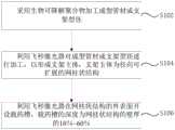
另一方面,结合图19所示,本发明还提供了一种可降解载药支架的制作方法,可降解载药支架的制作方法包括以下步骤:On the other hand, as shown in FIG. 19 , the present invention also provides a method for making a degradable drug-loaded stent, and the method for making a degradable drug-loaded stent includes the following steps:
步骤S102,采用生物可降解聚合物加工成型管材或支架型坯。In step S102, a biodegradable polymer is used to process a tube or a bracket parison.
其中,生物可降解聚合物包括下述一种或多种物质:聚乳酸(PLA)、聚左旋乳酸(PLLA)、聚乙交酯或聚羟基乙酸,PGA、聚氰基丙烯酸酯(PACA),聚己酸内酯(PCL)、聚酸酐类、聚乳酸共聚物(PLGA)、聚羟基丁酸戊酯(PHBV)、聚乙酰谷氨酸(PAGA)、聚正酯(POE)、聚氧化乙烯/聚丁烯共聚物(PEO/PBTP),聚原酸酯、聚己内酯、聚羟基乙酸、聚氧化乙烯/聚对苯二甲酸丁二酯共聚物、异丁烯酸盐或酯、甲基丙烯酸盐或酯、聚亚安酯、硅树脂、聚乙烯乙醇、乙烯基乙醇、聚羟基乙酸、聚磷酸酯酶,以及上述聚合物的单体中的至少两种形成的共聚物。利用生物可降解聚合物加工成型管材或支架型坯,能够进行体内降解,无需通过手术取出。Wherein, the biodegradable polymer includes one or more of the following: polylactic acid (PLA), poly-L-lactic acid (PLLA), polyglycolide or polyglycolic acid, PGA, polycyanoacrylate (PACA), Polycaprolactone (PCL), polyanhydrides, polylactic acid copolymer (PLGA), polyamyl hydroxybutyrate (PHBV), polyacetylglutamic acid (PAGA), polyorthoester (POE), polyethylene oxide /Polybutene copolymer (PEO/PBTP), polyorthoester, polycaprolactone, polyglycolic acid, polyethylene oxide/polybutylene terephthalate copolymer, methacrylate, methacrylic acid Salts or esters, polyurethanes, silicones, polyvinyl alcohol, vinyl alcohol, polyglycolic acid, polyphosphatase, and copolymers formed from at least two of the monomers of the foregoing polymers. Tube or stent parisons are fabricated from biodegradable polymers that can be degraded in vivo without the need for surgical removal.
步骤S104,利用飞秒激光器对成型管材或支架型坯进行加工,以形成支架主体10,支架主体10为径向可扩展的网柱状结构。In step S104 , the formed tube or the stent parison is processed by a femtosecond laser to form the
结合图1和图3所示,对于成型管材或支架型坯而言,通过飞秒激光器进行加工去除部分材料,开设镂空槽C,以形成径向可扩展的网柱状结构,即支架主体10。1 and 3 , for forming a tube or a bracket parison, a femtosecond laser is used to remove part of the material, and a hollow slot C is opened to form a radially expandable net-column structure, that is, the
步骤S106,利用飞秒激光器在网柱状结构的外表面10b开设载药槽13,载药槽13的深度为网柱状结构的壁厚的10%~60%。In step S106, a femtosecond laser is used to form a drug-carrying
在一些实施方式中,在加工载药槽13时,激光器持续出光,激光的聚焦点从开槽的起点位置移至终点位置,这样便可以在同等槽长的情况下,尽可能的减少载药槽13在支撑单元环11上留下的端部,也即减少了端部激光能量集中而出现材料击穿。这种结构形式下,既能够提供较多载药量,又能够减少击穿以防止支架主体10材料缺失而产生局部应力,降低支架主体10断裂风险。In some embodiments, when processing the drug-
在一些实施方式中,飞秒激光器开设载药槽13时,飞秒激光器的聚焦点在网柱状结构的外表面10b移动速度S满足如下条件:In some embodiments, when the femtosecond laser opens the drug-carrying
V<S≤10VV<S≤10V
其中,V为飞秒激光器对成型管材或支架型坯进行加工时,飞秒激光器的聚焦点相对成型管材或支架型坯的移动速度。Among them, V is the moving speed of the focal point of the femtosecond laser relative to the forming pipe or the bracket parison when the femtosecond laser is processing the formed pipe or the bracket parison.
该实施方式中,相对于在成型管材或支架型坯加工镂空槽时的切割速度,飞秒激光器开设载药槽13时,飞秒激光器的聚焦点在网柱状结构的外表面10b移动速度,即切割速度以更快的速度进行移动,减少单位切割长度所吸收的激光能量,降低支架主体10被击穿的风险。In this embodiment, when the femtosecond laser opens the drug-carrying
本申请的可降解载药支架,在生物可降解聚合物制成的支架主体10上开设载药槽13后,载药槽13能够改善药物在可降解载药支架上的附着能力,且载药槽13对可降解载药支架物理性能的影响控制在医疗器械标准范围内。In the degradable drug-carrying stent of the present application, after the drug-carrying
具体地,参照表2-表10,选用图3示出的可降解载药支架进行物理性能测试,以直径为2.5mm、3.0mm、4.0mm规格的支架进行分组对照实验。需要说明的是,支架的直径指的是呈扩展状态的网柱状结构的直径。即,选用的挖槽样品对应的网柱状结构的直径为2.5mm、3.0mm、4.0mm。同时,采用同等规格支架不作开槽处理作为参照样品进行物理性能测试,以供参照。Specifically, referring to Tables 2 to 10, the degradable drug-loaded stents shown in FIG. 3 were selected for physical performance tests, and stents with diameters of 2.5 mm, 3.0 mm, and 4.0 mm were used for group control experiments. It should be noted that the diameter of the stent refers to the diameter of the network columnar structure in the expanded state. That is, the diameters of the net columnar structures corresponding to the selected trench samples are 2.5 mm, 3.0 mm, and 4.0 mm. At the same time, the same specification bracket without groove treatment is used as a reference sample for physical property test for reference.
表2-表10中的序号1、2、3、4代表的是该规格型号下的第1、2、3、4号支架,其中1-4号支架的网柱状结构的壁厚约为125μm,1、2号支架为未挖槽支架;3、4号支架为挖槽支架。挖槽支架的载药槽13的深度控制在40μm-60μm;载药槽13在外表面10b的槽宽30±10μm,载药槽13的槽线沿支撑单元环11周向连续绕一周。径向抗挤压测试The
表2Table 2

表3table 3

表4Table 4


表2-表4分别列出了直径为2.5mm、3.0mm、4.0mm规格支架的径向抗挤压数据,由表2-4可知,挖槽样品相对参照样品的抗挤压性能相当,也就是说,在网柱状结构的外表面10b开设载药槽13后,仍具有较良好的径向抗挤压性能。Table 2-Table 4 lists the radial anti-extrusion data of stents with diameters of 2.5mm, 3.0mm and 4.0mm respectively. From Table 2-4, it can be seen that the anti-extrusion performance of the grooved sample is comparable to that of the reference sample. That is to say, after the drug-carrying
支架过度扩张测试Stent Overexpansion Test
支架过度扩张测试时,采用断裂直径作为衡量过度扩张性能的指标,其中,断裂直径是指支架经过一定的条件加工、存储、老化后,在37℃水域中使用球囊逐渐扩张支架,直至出现支撑单元环11断裂时支架所对应的直径。During the stent over-expansion test, the fracture diameter was used as an indicator to measure the over-expansion performance. The fracture diameter refers to the stent being processed, stored, and aged under certain conditions, and then the stent is gradually expanded with a balloon in water at 37°C until support occurs. The diameter corresponding to the stent when the
表5table 5

表6Table 6

表7Table 7


由表5-表7所示,挖槽样品相对参照样品的断裂直径相当,也就是说,在网柱状结构的外表面10b开设载药槽13后,支架过度扩张性能没有降低,仍具有较良好的支架过度扩张性能。As shown in Table 5-Table 7, the fracture diameter of the grooved sample is comparable to that of the reference sample, that is to say, after the drug-carrying
轴向回缩测试Axial retraction test
表8Table 8

表9Table 9

表10Table 10


由表8-10所示,同等规格的支架,参照样品和挖槽样品的轴向回缩差异不大,且轴向回缩都在5%以内,符合支架类医疗器械的使用标准。As shown in Table 8-10, for stents of the same specification, the axial retraction of the reference sample and the grooved sample is not much different, and the axial retraction is all within 5%, which meets the use standard of stent medical devices.
以上所述实施例的各技术特征可以进行任意的组合,为使描述简洁,未对上述实施例中的各个技术特征所有可能的组合都进行描述,然而,只要这些技术特征的组合不存在矛盾,都应当认为是本说明书记载的范围。The technical features of the above-described embodiments can be combined arbitrarily. For the sake of brevity, all possible combinations of the technical features in the above-described embodiments are not described. However, as long as there is no contradiction between the combinations of these technical features, All should be regarded as the scope described in this specification.
以上所述实施例仅表达了本发明的几种实施方式,其描述较为具体和详细,但并不能因此而理解为对发明专利范围的限制。应当指出的是,对于本领域的普通技术人员来说,在不脱离本发明构思的前提下,还可以做出若干变形和改进,这些都属于本发明的保护范围。因此,本发明专利的保护范围应以所附权利要求为准。The above-mentioned embodiments only represent several embodiments of the present invention, and the descriptions thereof are specific and detailed, but should not be construed as a limitation on the scope of the invention patent. It should be pointed out that for those of ordinary skill in the art, without departing from the concept of the present invention, several modifications and improvements can also be made, which all belong to the protection scope of the present invention. Therefore, the protection scope of the patent of the present invention should be subject to the appended claims.
Claims (10)
Priority Applications (5)
| Application Number | Priority Date | Filing Date | Title |
|---|---|---|---|
| CN201910389694.5ACN111904676A (en) | 2019-05-10 | 2019-05-10 | Degradable drug-loaded stent and manufacturing method thereof |
| US17/595,131US20220079786A1 (en) | 2019-05-10 | 2020-05-09 | Degradable drug-loaded stent and manufacturing method therefor |
| EP20806423.8AEP3967279B1 (en) | 2019-05-10 | 2020-05-09 | Degradable drug-loaded stent and manufacturing method therefor |
| PCT/CN2020/089349WO2020228629A1 (en) | 2019-05-10 | 2020-05-09 | Degradable drug-loaded stent and manufacturing method therefor |
| JP2022514032AJP7334338B2 (en) | 2019-05-10 | 2020-05-09 | Degradable drug-retaining stent and manufacturing method thereof |
Applications Claiming Priority (1)
| Application Number | Priority Date | Filing Date | Title |
|---|---|---|---|
| CN201910389694.5ACN111904676A (en) | 2019-05-10 | 2019-05-10 | Degradable drug-loaded stent and manufacturing method thereof |
Publications (1)
| Publication Number | Publication Date |
|---|---|
| CN111904676Atrue CN111904676A (en) | 2020-11-10 |
Family
ID=73241906
Family Applications (1)
| Application Number | Title | Priority Date | Filing Date |
|---|---|---|---|
| CN201910389694.5APendingCN111904676A (en) | 2019-05-10 | 2019-05-10 | Degradable drug-loaded stent and manufacturing method thereof |
Country Status (5)
| Country | Link |
|---|---|
| US (1) | US20220079786A1 (en) |
| EP (1) | EP3967279B1 (en) |
| JP (1) | JP7334338B2 (en) |
| CN (1) | CN111904676A (en) |
| WO (1) | WO2020228629A1 (en) |
Cited By (1)
| Publication number | Priority date | Publication date | Assignee | Title |
|---|---|---|---|---|
| CN117086497A (en)* | 2023-10-18 | 2023-11-21 | 昆山允可精密工业技术有限公司 | Drug coating support laser cutting assembly and laser cutting system |
Families Citing this family (1)
| Publication number | Priority date | Publication date | Assignee | Title |
|---|---|---|---|---|
| CN116059002A (en)* | 2021-11-04 | 2023-05-05 | 上海博畅医疗科技有限公司 | Braided stent, braided stent system and preparation method of woven stent |
Citations (7)
| Publication number | Priority date | Publication date | Assignee | Title |
|---|---|---|---|---|
| CN201019862Y (en)* | 2007-04-06 | 2008-02-13 | 微创医疗器械(上海)有限公司 | Blood vessel supporting with medicament carrying groove |
| CN101879102A (en)* | 2009-05-07 | 2010-11-10 | 微创医疗器械(上海)有限公司 | Groove carrying-type coating decomposable drug eluting stent |
| CN102379762A (en)* | 2011-08-02 | 2012-03-21 | 微创医疗器械(上海)有限公司 | Biodegradable stent with groove and preparation method thereof |
| CN103582466A (en)* | 2011-05-03 | 2014-02-12 | 帕尔玛兹科学公司 | Endoluminal implantable surfaces and method of making the same |
| CN104053457A (en)* | 2011-08-19 | 2014-09-17 | 先进生物假体表面有限公司 | Grooved drug-eluting medical devices and method of making same |
| CN107049571A (en)* | 2017-05-12 | 2017-08-18 | 微创神通医疗科技(上海)有限公司 | A kind of vertebral artery stent and preparation method thereof |
| CN107088110A (en)* | 2017-06-15 | 2017-08-25 | 微创神通医疗科技(上海)有限公司 | Vertebral artery stent and preparation method thereof |
Family Cites Families (12)
| Publication number | Priority date | Publication date | Assignee | Title |
|---|---|---|---|---|
| US6273913B1 (en)* | 1997-04-18 | 2001-08-14 | Cordis Corporation | Modified stent useful for delivery of drugs along stent strut |
| BR0016957A (en)* | 2000-12-15 | 2004-06-22 | Narayan Badari Nagarada Gadde | Arterial venous graft with drug delivery system (s) and process for treating sequential biological events that occur in response to graft implantation and drug delivery system |
| DE60120955T3 (en)* | 2001-07-20 | 2015-06-25 | Cid S.P.A. | stent |
| CN1605366A (en)* | 2004-12-03 | 2005-04-13 | 北京美中双和医疗器械有限公司 | Vascular stent mounted with non penetrable slot or blind hole and its preparing method |
| CN101732114B (en)* | 2008-11-04 | 2014-07-30 | 上海微创医疗器械(集团)有限公司 | Coronary artery stent with medicine carrying grooves |
| CN101987049B (en)* | 2009-07-30 | 2014-10-01 | 上海微创医疗器械(集团)有限公司 | Method and device for loading medicine and/or polymers on medical appliance |
| US10117764B2 (en)* | 2010-10-29 | 2018-11-06 | CARDINAL HEALTH SWITZERLAND 515 GmbH | Bare metal stent with drug eluting reservoirs having improved drug retention |
| CN203677324U (en)* | 2013-12-24 | 2014-07-02 | 江苏省华星医疗器械实业有限公司 | High drug-loading-capacity intravascular stent |
| CN206482699U (en)* | 2016-07-21 | 2017-09-12 | 成都嘉宝祥生物科技有限公司 | A kind of coronary vessel stent |
| CN106137483B (en)* | 2016-07-21 | 2018-10-02 | 成都嘉宝祥生物科技有限公司 | A kind of coronary vessel stent production method |
| JP2018078990A (en)* | 2016-11-15 | 2018-05-24 | テルモ株式会社 | Stent |
| CN108938158A (en)* | 2018-07-23 | 2018-12-07 | 上海市第人民医院 | A kind of load medicine intravascular stent based on nano-medicament carrier |
- 2019
- 2019-05-10CNCN201910389694.5Apatent/CN111904676A/enactivePending
- 2020
- 2020-05-09WOPCT/CN2020/089349patent/WO2020228629A1/ennot_activeCeased
- 2020-05-09USUS17/595,131patent/US20220079786A1/enactivePending
- 2020-05-09EPEP20806423.8Apatent/EP3967279B1/enactiveActive
- 2020-05-09JPJP2022514032Apatent/JP7334338B2/enactiveActive
Patent Citations (7)
| Publication number | Priority date | Publication date | Assignee | Title |
|---|---|---|---|---|
| CN201019862Y (en)* | 2007-04-06 | 2008-02-13 | 微创医疗器械(上海)有限公司 | Blood vessel supporting with medicament carrying groove |
| CN101879102A (en)* | 2009-05-07 | 2010-11-10 | 微创医疗器械(上海)有限公司 | Groove carrying-type coating decomposable drug eluting stent |
| CN103582466A (en)* | 2011-05-03 | 2014-02-12 | 帕尔玛兹科学公司 | Endoluminal implantable surfaces and method of making the same |
| CN102379762A (en)* | 2011-08-02 | 2012-03-21 | 微创医疗器械(上海)有限公司 | Biodegradable stent with groove and preparation method thereof |
| CN104053457A (en)* | 2011-08-19 | 2014-09-17 | 先进生物假体表面有限公司 | Grooved drug-eluting medical devices and method of making same |
| CN107049571A (en)* | 2017-05-12 | 2017-08-18 | 微创神通医疗科技(上海)有限公司 | A kind of vertebral artery stent and preparation method thereof |
| CN107088110A (en)* | 2017-06-15 | 2017-08-25 | 微创神通医疗科技(上海)有限公司 | Vertebral artery stent and preparation method thereof |
Cited By (2)
| Publication number | Priority date | Publication date | Assignee | Title |
|---|---|---|---|---|
| CN117086497A (en)* | 2023-10-18 | 2023-11-21 | 昆山允可精密工业技术有限公司 | Drug coating support laser cutting assembly and laser cutting system |
| CN117086497B (en)* | 2023-10-18 | 2024-01-30 | 昆山允可精密工业技术有限公司 | Drug coating support laser cutting assembly and laser cutting system |
Also Published As
| Publication number | Publication date |
|---|---|
| EP3967279B1 (en) | 2025-08-13 |
| JP2022542483A (en) | 2022-10-03 |
| EP3967279C0 (en) | 2025-08-13 |
| EP3967279A4 (en) | 2023-06-07 |
| US20220079786A1 (en) | 2022-03-17 |
| WO2020228629A1 (en) | 2020-11-19 |
| JP7334338B2 (en) | 2023-08-28 |
| EP3967279A1 (en) | 2022-03-16 |
Similar Documents
| Publication | Publication Date | Title |
|---|---|---|
| JP2018167066A (en) | Endoprosthesis | |
| JP5895324B2 (en) | How to create drug-eluting medical devices | |
| JP5895325B2 (en) | How to create drug-eluting medical devices | |
| TWI489980B (en) | Surface textured implants | |
| CN102307613B (en) | Percutaneous retrievable vascular filter | |
| JP6124026B2 (en) | Improved scaffold for peripheral applications | |
| CN113633434A (en) | Implantable stent for treating sinusitis | |
| US11478348B2 (en) | Medical implants having managed biodegradation | |
| CN107405432A (en) | Stent constructs with radiopaque markers | |
| CN104244873B (en) | Hollow drug-filled stent and method for forming the hollow drug-filled stent | |
| CN104220030B (en) | Hollow drug-filled stent and method for forming hollow drug-filled stent | |
| CN111904676A (en) | Degradable drug-loaded stent and manufacturing method thereof | |
| US20170203494A1 (en) | Method to manufacture thin strut stent from bioabsorbable polymer with high fatigue and radial strength | |
| US20120055011A1 (en) | Methods for manufacturing implantable stents having a plurality of varying parallelogrammic cells | |
| US20170246243A1 (en) | Bioresorbable scaffold for treatment of bifurcation lesion | |
| US10675387B2 (en) | Multi stage radial deformation for manufacturing thin strut stent from bioabsorbable polymer | |
| CN101069660B (en) | A preparation method of biliary stent carrying drugs | |
| CN109922760B (en) | Drug-filled stent for preventing vascular micro-injury and manufacturing method thereof | |
| CN111658056A (en) | Embolism particle for medical use and preparation method thereof | |
| US10022252B2 (en) | Spiral blood flow device with diameter independent helix angle | |
| JP5445649B2 (en) | Stent | |
| WO2020059518A1 (en) | Scaffold system and scaffold mounting method | |
| JP2006262948A (en) | Stent |
Legal Events
| Date | Code | Title | Description |
|---|---|---|---|
| PB01 | Publication | ||
| PB01 | Publication | ||
| SE01 | Entry into force of request for substantive examination | ||
| SE01 | Entry into force of request for substantive examination | ||
| RJ01 | Rejection of invention patent application after publication | ||
| RJ01 | Rejection of invention patent application after publication | Application publication date:20201110 |