CN111904505A - Medical instrument - Google Patents
Medical instrumentDownload PDFInfo
- Publication number
- CN111904505A CN111904505ACN201910390807.3ACN201910390807ACN111904505ACN 111904505 ACN111904505 ACN 111904505ACN 201910390807 ACN201910390807 ACN 201910390807ACN 111904505 ACN111904505 ACN 111904505A
- Authority
- CN
- China
- Prior art keywords
- limit
- reset
- assembly
- reset switch
- elastic member
- Prior art date
- Legal status (The legal status is an assumption and is not a legal conclusion. Google has not performed a legal analysis and makes no representation as to the accuracy of the status listed.)
- Pending
Links
Images


Classifications
- A—HUMAN NECESSITIES
- A61—MEDICAL OR VETERINARY SCIENCE; HYGIENE
- A61B—DIAGNOSIS; SURGERY; IDENTIFICATION
- A61B17/00—Surgical instruments, devices or methods
- A61B17/068—Surgical staplers, e.g. containing multiple staples or clamps
- A61B17/072—Surgical staplers, e.g. containing multiple staples or clamps for applying a row of staples in a single action, e.g. the staples being applied simultaneously
- A61B17/07207—Surgical staplers, e.g. containing multiple staples or clamps for applying a row of staples in a single action, e.g. the staples being applied simultaneously the staples being applied sequentially
- A—HUMAN NECESSITIES
- A61—MEDICAL OR VETERINARY SCIENCE; HYGIENE
- A61B—DIAGNOSIS; SURGERY; IDENTIFICATION
- A61B17/00—Surgical instruments, devices or methods
- A61B17/11—Surgical instruments, devices or methods for performing anastomosis; Buttons for anastomosis
- A61B17/115—Staplers for performing anastomosis, e.g. in a single operation
- A—HUMAN NECESSITIES
- A61—MEDICAL OR VETERINARY SCIENCE; HYGIENE
- A61B—DIAGNOSIS; SURGERY; IDENTIFICATION
- A61B17/00—Surgical instruments, devices or methods
- A61B2017/00367—Details of actuation of instruments, e.g. relations between pushing buttons, or the like, and activation of the tool, working tip, or the like
- A61B2017/00407—Ratchet means
- A—HUMAN NECESSITIES
- A61—MEDICAL OR VETERINARY SCIENCE; HYGIENE
- A61B—DIAGNOSIS; SURGERY; IDENTIFICATION
- A61B17/00—Surgical instruments, devices or methods
- A61B17/068—Surgical staplers, e.g. containing multiple staples or clamps
- A61B17/072—Surgical staplers, e.g. containing multiple staples or clamps for applying a row of staples in a single action, e.g. the staples being applied simultaneously
- A61B2017/07214—Stapler heads
- A61B2017/07285—Stapler heads characterised by its cutter
Landscapes
- Health & Medical Sciences (AREA)
- Life Sciences & Earth Sciences (AREA)
- Surgery (AREA)
- Heart & Thoracic Surgery (AREA)
- Engineering & Computer Science (AREA)
- Biomedical Technology (AREA)
- Nuclear Medicine, Radiotherapy & Molecular Imaging (AREA)
- Medical Informatics (AREA)
- Molecular Biology (AREA)
- Animal Behavior & Ethology (AREA)
- General Health & Medical Sciences (AREA)
- Public Health (AREA)
- Veterinary Medicine (AREA)
- Surgical Instruments (AREA)
Abstract
Translated fromChinese
Description
Translated fromChinese技术领域technical field
本发明属于医疗器械技术领域,涉及一种医疗器械,尤其涉及一种可用操作手复位的医 疗器械。The invention belongs to the technical field of medical devices, and relates to a medical device, in particular to a medical device that can be reset by an operator.
背景技术Background technique
近年来,市场上出现了设有复位机构的医疗器械,如吻合器。吻合器是一种外科手术器 械,它的作用原理是通过前端夹钳部分闭合以夹持组织,再将吻合器钉仓中的金属缝合钉推 出压紧成形,从而把组织缝合在一起。在有些吻合器中,钳口部分还装有切割刀,能在组织 缝合的过程中把缝合好的组织切断开。In recent years, medical devices with reduction mechanisms, such as staplers, have appeared on the market. The stapler is a surgical instrument. Its principle of action is to partially close the front-end clamp to clamp the tissue, and then push the metal staples in the staple cartridge to compress and form, so as to sew the tissue together. In some staplers, the jaw portion is also equipped with a cutting knife, which can cut the sutured tissue during the process of tissue suture.
图1为现有的吻合器的结构示意图;请参阅图1,具有上述功能的吻合器包括有一个执行 器4、中间连接体和控制器2(手柄部分);手柄部分包括复位帽31,通过复位帽31进行复 位操作。Figure 1 is a schematic diagram of the structure of the existing stapler; please refer to Figure 1, the stapler with the above functions includes an actuator 4, an intermediate connecting body and a controller 2 (handle part); the handle part includes a
通常,从夹持组织、推钉缝合、切割组织,到切割刀退出、松开组织的一系列动作,主 要依靠一根中间连接体的中心推杆的前后运动实现,而中心推杆又与后端手柄部分的击发齿 条相连。Usually, a series of actions from clamping tissue, pushing staples for suturing, cutting tissue, to cutting knife withdrawing and loosening tissue are mainly realized by the forward and backward movement of the central push rod of an intermediate connecting body, and the central push rod is connected with the rear The firing rack of the end handle portion is connected.
击发齿条的前进是通过扣动击发扳机,扳机上的拨齿带动击发齿条向前运动完成。击发 齿条的后退是通过回拉击发齿条上的复位帽,带动击发齿条向后运动完成;也称为击发齿条 的复位。The advancement of the firing rack is accomplished by pulling the firing trigger, and the teeth on the trigger drive the firing rack to move forward. The backward movement of the firing rack is accomplished by pulling back the reset cap on the firing rack to drive the firing rack to move backwards; it is also called the reset of the firing rack.
执行器由钉砧组件、钉仓组件和驱动组件组成。钉砧组件包含一个钉成型面,钉成型面 包含多排钉槽,钉槽用于金属缝合钉的成型。钉仓组件一般包括钉仓、缝合钉、推钉块和推 钉滑块和钉仓座,钉仓的上表面为组织接触面,钉仓安装在钉仓座中。钉砧组件在近端与钉 仓组件的近端可动地连接在一起,并可以在张开状态和关闭状态之间转换。驱动组件与传动 机构连接,用于把击发扳机的动作转换为执行器的关闭、击发和张开动作。一般情况下,钉 砧组件和钉仓座还各包含一个纵向槽,上述纵向槽用于容纳驱动组件通过。当驱动组件通过 上述纵向槽向执行器的远端运动时,会驱使钉砧组件和钉仓组件从张开状态转换为关闭状态, 并且驱使推钉滑块和推钉块顶出缝合钉并在钉砧组件的钉成型面的钉槽中成型。一般情况下, 驱动组件还包括一个切割刀,用于在组织被缝合钉缝合后,在多排钉线之间切割组织。控制 器用于手动控制操作器械,一般包括有一个固定手柄,一个与固定手柄相对可动连接的击发 扳机,一组传递击发扳机动作至执行器的传动机构,一个手动复位组件。当执行器的钉仓组 件与钉砧组件处于闭合状态时,操作手动复位组件能驱使钉仓组件与钉砧组件恢复张开状态。 中间连接体与控制器的远端可动地连接,并与执行器的近端连接在一起,中间连接体构成一 个连接通道,用于实现将击发扳机的动作传递给执行器。The actuator consists of a nail anvil assembly, a nail cartridge assembly and a driving assembly. The staple anvil assembly includes a staple forming surface, and the staple forming surface contains multiple rows of staple grooves, and the staple grooves are used for forming metal staples. The staple cartridge assembly generally includes a staple cartridge, staples, a staple pushing block, a staple pushing slider, and a staple cartridge seat. The upper surface of the staple cartridge is a tissue contact surface, and the staple cartridge is installed in the staple cartridge seat. The anvil assembly is movably connected at the proximal end to the proximal end of the cartridge assembly and is switchable between an open state and a closed state. The drive assembly is connected to the transmission mechanism for converting the action of the firing trigger into the closing, firing and opening actions of the actuator. Generally, the anvil assembly and the staple cartridge seat each include a longitudinal groove, and the longitudinal groove is used for accommodating the driving assembly to pass therethrough. When the driving assembly moves toward the distal end of the actuator through the above-mentioned longitudinal groove, the anvil assembly and the staple cartridge assembly are driven to convert from the open state to the closed state, and the staple pusher slider and the staple pusher block are driven to eject the staples and push out the staples at the same time. It is formed in the nail groove of the nail forming surface of the nail anvil assembly. Typically, the drive assembly also includes a cutting blade for cutting tissue between the rows of staples after the tissue has been stapled. The controller is used to manually control the operating instrument, and generally includes a fixed handle, a firing trigger relatively movably connected to the fixed handle, a set of transmission mechanisms that transmit the action of the firing trigger to the actuator, and a manual reset assembly. When the staple cartridge assembly and the staple anvil assembly of the actuator are in the closed state, operating the manual reset assembly can drive the staple cartridge assembly and the staple anvil assembly to return to the open state. The intermediate connecting body is movably connected with the distal end of the controller, and is connected with the proximal end of the actuator, and the intermediate connecting body constitutes a connection channel, which is used to transmit the action of the firing trigger to the actuator.
现有吻合器在进行击发齿条复位时,操作者需要用另一只手回拉复位帽完成复位。例如, 在美国专利US5,865,361中,当击发吻合器的击发扳机时,吻合器的钉砧组件和钉仓组件将 从张开状态转变为关闭状态,夹持住目标组织。在手术中,如果医生认为需要调整夹持组织 的位置,那么医生需要用另一只手向回拉手动复位组件,驱使钉仓组件与钉砧组件恢复张开 状态。在实际手术中,吻合器的目标组织包括胃、肺、大肠等组织,其中,胃和大肠这些组 织一般比较厚,且组织内腔有丰富的折皱,表面可能还有未完全分离的脂肪组织;而肺组织 里有大量的肺泡,因此,吻合器的执行器在第一次关闭并夹持上述组织时,由于组织的厚度、 折皱、脂肪组织或者组织内的气泡等原因,组织一般难以被压缩至理想的均匀厚度。通过反 复在同一部位夹持组织,可以有效消除上述因素引起的组织压缩不均匀现象,使吻合器在随 后驱使钛钉吻合组织及切割组织时,钛钉成形高度均匀,吻合效果好,组织切缘光滑。要实 现在同一组织部位反复夹持组织,医生需要松开另一只手握持的器械,反复用双手操作吻合 器的击发扳机和手动复位扳机。另外,吻合器的执行器在正确夹持组织以后,医生在决定吻 合和切割组织前,首先需要用另一只手辅助按下吻合器的击发保险按钮以打开击发保险装置, 然后才能再次操作击发扳机执行后续动作,这给器械操作带来不便,给手术带来额外风险。 在微创外科手术中,医生有时两只手分别操作不同的器械,如果某一器械需要两只手同时操 作,医生需要先松开握持的另一个器械。在微创外科手术中,未受医生控制的器械位于体外 的控制器有可能因为术中意外的触碰而移位,器械控制器的少量移位就可能造成器械远端的 执行器的大量非受控移位;因器械远端的执行器与手术目标区内的组织和器官很靠近,执行 器的非受控移位有可能损伤附近的组织和器官。在临时不操作器械室,有些医生会将该器械 抽出体外,以避免风险;有些情况下,器械会由另外的医生临时接手扶握住;有时,医生只 是松开器械,而将器械的远端压靠在某些组织上或组织的间隙中,这些举动要么会延长手术 时间,要么存在损伤组织和器官的风险。In the existing stapler, when the firing rack is reset, the operator needs to use the other hand to pull back the reset cap to complete the reset. For example, in US Pat. No. 5,865,361, when the firing trigger of the stapler is fired, the stapler anvil assembly and staple cartridge assembly of the stapler will transition from an open state to a closed state, gripping the target tissue. During the operation, if the doctor thinks that the position of holding the tissue needs to be adjusted, the doctor needs to use the other hand to pull back the manual reset assembly to drive the cartridge assembly and the anvil assembly to return to the open state. In actual surgery, the target tissues of the stapler include stomach, lung, large intestine and other tissues. Among them, the stomach and large intestine are generally thicker, and there are abundant folds in the inner cavity of the tissue, and there may be incompletely separated adipose tissue on the surface; There are a large number of alveoli in the lung tissue. Therefore, when the actuator of the stapler closes and clamps the above-mentioned tissue for the first time, the tissue is generally difficult to be compressed due to the thickness of the tissue, wrinkles, adipose tissue or air bubbles in the tissue. to the ideal uniform thickness. By repeatedly clamping the tissue at the same position, the phenomenon of uneven tissue compression caused by the above factors can be effectively eliminated, so that when the stapler drives the titanium nails to anastomize and cut the tissue, the titanium nails are highly uniform, the anastomosis effect is good, and the tissue incision margin is good. smooth. To achieve repeated tissue clamping at the same tissue site, the physician needs to release the instrument held in the other hand and repeatedly operate the stapler firing trigger and manual reset trigger with both hands. In addition, after the actuator of the stapler properly clamps the tissue, before deciding to staple and cut the tissue, the doctor first needs to use the other hand to assist the firing safety button of the stapler to open the firing safety device, and then can operate the firing again The trigger performs subsequent actions, which inconvenience the instrument and create additional risks for the procedure. In minimally invasive surgery, doctors sometimes operate different instruments with two hands. If a certain instrument requires two hands to operate at the same time, the doctor needs to release the other instrument that is being held. In minimally invasive surgery, the controller outside the body of the instrument that is not controlled by the doctor may be displaced due to accidental touch during the operation. Controlled displacement; because the actuator at the distal end of the instrument is in close proximity to tissue and organs within the surgical target area, uncontrolled displacement of the actuator has the potential to damage nearby tissue and organs. When the instrument room is not operated temporarily, some doctors will take the instrument out of the body to avoid risks; in some cases, the instrument will be temporarily taken over by another doctor to hold it; Pressing against certain tissues or in the spaces between tissues can either prolong the operation time or risk damaging tissues and organs.
有鉴于此,如今迫切需要设计一种新的吻合器,以便克服现有吻合器存在的上述诸多缺 陷。In view of this, there is an urgent need to design a new stapler in order to overcome many of the above-mentioned shortcomings of existing staplers.
发明内容SUMMARY OF THE INVENTION
本发明提供一种医疗器械,可方便操作者在一只手在握住医疗器械的同时还能完成击发 医疗器械的复位动作。The invention provides a medical instrument, which can facilitate the operator to complete the reset action of firing the medical instrument while holding the medical instrument with one hand.
为解决上述技术问题,根据本发明的一个方面,采用如下技术方案:In order to solve the above-mentioned technical problems, according to one aspect of the present invention, the following technical solutions are adopted:
一种医疗器械包括执行机构、连接机构以及控制机构,所述控制机构通过连接机构连接 执行机构;A medical device includes an executive mechanism, a connection mechanism and a control mechanism, the control mechanism is connected to the execution mechanism through the connection mechanism;
所述控制机构包括击发组件、复位机构以及限位组件;The control mechanism includes a firing assembly, a reset mechanism and a limit assembly;
所述击发组件被击发后能够向第一方向移动,实现执行机构的第一动作;The firing assembly can move in the first direction after being fired to realize the first action of the actuator;
所述限位组件连接击发组件,在击发组件向第一方向移动一定距离后能限制所述击发组 件向第二方向移动;The limiting component is connected to the firing component, and can restrict the firing component from moving to the second direction after the firing component moves to the first direction for a certain distance;
所述复位机构连接限位组件,在击发组件被限位组件限制向第二方向移动后,所述复位 机构能调节所述限位组件的位置,使所述限位组件解除对击发组件的限位,使得所述击发组 件可向第二方向移动。The reset mechanism is connected to the limit assembly, and after the firing assembly is restricted from moving in the second direction by the limit assembly, the reset mechanism can adjust the position of the limit assembly, so that the limit assembly releases the limit on the firing assembly. position so that the firing assembly can move in the second direction.
作为本发明的一种实施方式,所述复位机构包括复位开关、传动件,所述限位组件包括 限位滑块;所述复位开关与所述传动件连动,拨动所述复位开关至复位开启位置,所述传动 件将驱使所述限位滑块向预设方向移动,所述限位滑块解除对所述击发组件的限位。As an embodiment of the present invention, the reset mechanism includes a reset switch and a transmission member, and the limit assembly includes a limit slider; the reset switch is linked with the transmission member, and the reset switch is toggled to When the open position is reset, the transmission member will drive the limit slider to move in a preset direction, and the limit slider will release the limit on the firing assembly.
进一步地,所述复位开关和传动件可一体式,或分体连接。Further, the reset switch and the transmission member can be integrated or connected separately.
进一步地,所述传动件是转动结构或者滑动结构。Further, the transmission member is a rotating structure or a sliding structure.
进一步地,所述传动件为转动结构,所述复位开关与转动结构的第一端连动,拨动所述 复位开关至复位开启位置,所述转动结构的第二端将驱使所述限位滑块向预设方向移动,所 述限位滑块解除对所述击发组件的限位。Further, the transmission member is a rotating structure, the reset switch is linked with the first end of the rotating structure, and the reset switch is toggled to the reset open position, and the second end of the rotating structure will drive the limiter. The slider moves in a preset direction, and the limit slider releases the limit on the firing assembly.
进一步地,所述复位机构还包括转动结构弹性件,所述限位组件还包括限位滑块弹性件, 所述转动结构弹性件连接所述转动结构,所述限位滑块弹性件连接所述限位滑块。Further, the reset mechanism further includes a rotating structural elastic member, the limiting assembly further includes a limiting sliding block elastic member, the rotating structural elastic member is connected to the rotating structure, and the limiting sliding block elastic member is connected to the rotating structure. the limit slider.
进一步地,所述转动结构弹性件为拉簧,所述限位滑块弹性件为扭簧。Further, the elastic member of the rotating structure is a tension spring, and the elastic member of the limit slider is a torsion spring.
作为本发明的一种实施方式,所述限位组件包括限位滑块、第一弹性件、第一复位开关 弹性件;所述复位机构包括复位开关;所述第一弹性件的第一端连接复位开关,第二端连接 限位滑块,使得第一弹性件能与复位开关、限位滑块双向作用;第一复位开关弹性件一端压 在复位开关上,另一端固定在外壳相应结构上;当拨动复位开关至复位开启位置,复位开关 与第一弹性件的第一端连动,第一弹性件转动设定角度,第一弹性件的第二端将限位滑块向 预设方向拨动,所述限位滑块解除对击发组件的限位。As an embodiment of the present invention, the limit assembly includes a limit slider, a first elastic member, and a first reset switch elastic member; the reset mechanism includes a reset switch; the first end of the first elastic member The reset switch is connected to the reset switch, and the second end is connected to the limit slider, so that the first elastic member can act in both directions with the reset switch and the limit slider; one end of the elastic member of the first reset switch is pressed on the reset switch, and the other end is fixed on the corresponding structure of the casing When the reset switch is toggled to the reset open position, the reset switch is linked with the first end of the first elastic member, the first elastic member rotates to a set angle, and the second end of the first elastic member pushes the limit slider to the preset position. When the direction is toggled, the limit slider releases the limit on the firing assembly.
进一步地,所述第一弹性件为扭簧,所述第一复位开关弹性件为扭簧。Further, the first elastic member is a torsion spring, and the first reset switch elastic member is a torsion spring.
作为本发明的一种实施方式,所述限位组件包括至少一限位块,所述限位块设置在所述 复位机构上,所述复位机构包括复位开关、第二复位开关弹性件;所述击发组件包括齿条, 齿条设有限位台阶;第二复位开关弹性件的一端作用于复位开关上,另一端固定于外壳相应 结构上;所述限位块卡在齿条的限位台阶处;当拨动复位开关至复位开启位置,复位开关上 的限位块一同向预设方向移动至非限位处,所述限位滑块解除对击发组件的限位。As an embodiment of the present invention, the limit assembly includes at least one limit block, and the limit block is arranged on the reset mechanism, and the reset mechanism includes a reset switch and a second reset switch elastic member; The firing assembly includes a rack, and the rack is provided with a limit step; one end of the second reset switch elastic member acts on the reset switch, and the other end is fixed on the corresponding structure of the casing; the limit block is stuck on the limit step of the rack when the reset switch is toggled to the reset open position, the limit blocks on the reset switch move together in a preset direction to the non-limit position, and the limit slider releases the limit on the firing assembly.
进一步地,所述第二复位开关弹性件为压簧。Further, the second reset switch elastic member is a compression spring.
作为本发明的一种实施方式,所述限位组件包括至少一限位块,所述限位块设置在所述 复位机构上,所述复位机构包括复位开关、第三复位开关弹性件;所述击发组件包括齿条, 齿条设有限位台阶,限位台阶至少占据横向第一侧的一定宽度;所述限位块卡在齿条的限位 台阶处;当拨动复位开关至复位开启位置,复位开关上的限位块一同向第二侧平移,至完全 让开齿条上的限位台阶。As an embodiment of the present invention, the limit assembly includes at least one limit block, and the limit block is arranged on the reset mechanism, and the reset mechanism includes a reset switch and a third reset switch elastic member; The firing assembly includes a rack, the rack is provided with a limit step, and the limit step occupies at least a certain width of the lateral first side; the limit block is stuck at the limit step of the rack; when the reset switch is toggled to reset and open position, the limit block on the reset switch moves to the second side together until the limit step on the rack is completely cleared.
进一步地,所述第三复位开关弹性件为压簧。Further, the third reset switch elastic member is a compression spring.
作为本发明的一种实施方式,所述控制机构包括回拉组件,所述回拉组件连接所述击发 组件,能向所述击发组件施加所述第二方向的回拉力。As an embodiment of the present invention, the control mechanism includes a pullback assembly, which is connected to the firing assembly and can apply a pullback force in the second direction to the firing assembly.
进一步地,所述击发组件包括齿条,所述齿条有齿的一侧与所述扳机组件配合;所述齿 条设有回拉连接机构,所述回拉组件与回拉连接机构配合。Further, the firing assembly includes a rack, and the toothed side of the rack cooperates with the trigger assembly; the rack is provided with a pullback connection mechanism, and the pullback assembly cooperates with the pullback connection mechanism.
作为本发明的一种实施方式,所述击发组件为击发齿条组件,所述击发齿条组件还包括 复位帽、复位片,在复位帽被施以设定回拉力的状态下,复位帽带动复位片推开限位滑块, 所述限位滑块解除对所述击发组件的限位。As an embodiment of the present invention, the firing assembly is a firing rack assembly, and the firing rack assembly further includes a reset cap and a reset sheet. When the reset cap is applied with a set return force, the reset cap drives the The reset piece pushes away the limit slider, and the limit slider releases the limit on the firing assembly.
作为本发明的一种实施方式,所述执行器包括夹钳、切割刀部件以及夹钳弹片;所述连 接机构包括中心推杆,所述击发组件包括齿条;As an embodiment of the present invention, the actuator includes a clamp, a cutting knife part and a clamp spring; the connecting mechanism includes a central push rod, and the firing assembly includes a rack;
所述中心推杆连接切割刀部件,所述切割刀部件在第一位置时,能压住夹钳,使得夹钳 夹持夹钳弹片;所述切割刀部件在第二位置时,切割刀部件不再压住夹钳,夹钳在夹钳弹片 的作用下张开;The central push rod is connected to the cutting knife part, and when the cutting knife part is in the first position, it can press the clamp, so that the clamp clamps the clamp spring; when the cutting knife part is in the second position, the cutting knife part The clamp is no longer pressed, and the clamp is opened under the action of the clamp shrapnel;
在复位机构做出击发动作时,所述中心推杆跟随齿条一起向第二方向移动,中心推杆与 切割刀部件连动,切割刀部件退至夹钳后方,切割刀部件上的挡块结构不再压住夹钳,夹钳 在夹钳弹片的作用下张开。When the reset mechanism performs the firing action, the central push rod moves in the second direction along with the rack, the central push rod is linked with the cutting knife part, the cutting knife part retreats to the back of the clamp, and the stopper on the cutting knife part The structure no longer presses the clamp, and the clamp opens under the action of the clamp shrapnel.
作为本发明的一种实施方式,所述执行器为可拆卸的再装载器,或者所述执行器与连接 机构连接。As an embodiment of the present invention, the actuator is a detachable reloader, or the actuator is connected with a connecting mechanism.
进一步地,所述医疗器械包括钉仓组件,钉仓组件可拆卸地安装于所述执行器的夹钳上。Further, the medical device includes a staple cartridge assembly, and the staple cartridge assembly is detachably mounted on the clamp of the actuator.
作为本发明的一种实施方式,所述医疗器械为吻合器。As an embodiment of the present invention, the medical device is a stapler.
本发明的有益效果在于:本发明提出的医疗器械,可方便操作者在一只手在握住医疗器 械(如吻合器)的同时还能完成击发齿条的复位动作。The beneficial effect of the present invention is that the medical device provided by the present invention can facilitate the operator to complete the reset action of the firing rack while holding the medical device (such as a stapler) with one hand.
附图说明Description of drawings
图1为现有的吻合器的结构示意图。FIG. 1 is a schematic structural diagram of a conventional stapler.
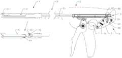
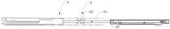
图2为本发明一实施例中吻合器的结构示意图。FIG. 2 is a schematic structural diagram of a stapler in an embodiment of the present invention.
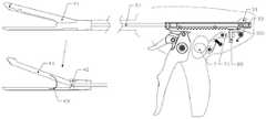
图3为本发明一实施例中吻合器的结构示意图(复位前状态并通过复位开关进行复位操 作)。Fig. 3 is a schematic diagram of the structure of the stapler in an embodiment of the present invention (the state before reset and the reset operation is performed by the reset switch).
图4为本发明一实施例中吻合器的结构示意图(复位后状态)。FIG. 4 is a schematic diagram of the structure of the stapler in an embodiment of the present invention (the state after reset).
图5为本发明一实施例中吻合器的结构示意图(复位前状态并通过复位帽进行复位操作)。FIG. 5 is a schematic structural diagram of the stapler in an embodiment of the present invention (the state before reset and the reset operation is performed through the reset cap).
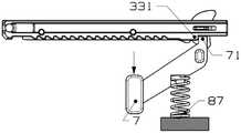
图6为本发明一实施例中吻合器限位组件的结构示意图(复位前状态)。FIG. 6 is a schematic structural diagram of a stapler limiting assembly in an embodiment of the present invention (state before reset).
图7为本发明一实施例中吻合器限位组件的结构示意图(复位后状态)。FIG. 7 is a schematic structural diagram of a stapler limiting assembly in an embodiment of the present invention (reset state).
图8为本发明一实施例中吻合器限位组件的结构示意图(复位前状态)。FIG. 8 is a schematic structural diagram of a stapler limiting assembly in an embodiment of the present invention (state before reset).
图9为本发明一实施例中吻合器限位组件的结构示意图(复位后状态)。FIG. 9 is a schematic structural diagram of a stapler limiting assembly in an embodiment of the present invention (reset state).
图10为本发明一实施例中吻合器限位组件的结构示意图(复位前状态主视图)。10 is a schematic structural diagram of a stapler limiting assembly in an embodiment of the present invention (front view of the state before reset).
图11为本发明一实施例中吻合器限位组件的结构示意图(复位前状态侧视图)。FIG. 11 is a schematic structural diagram of a stapler limiting assembly according to an embodiment of the present invention (a side view in a state before reset).
图12为本发明一实施例中吻合器限位组件的结构示意图(复位后状态)。FIG. 12 is a schematic structural diagram of a stapler limiting assembly in an embodiment of the present invention (reset state).
图13为本发明一实施例中吻合器的回拉组件结构示意图。FIG. 13 is a schematic structural diagram of the retraction assembly of the stapler according to an embodiment of the present invention.
图14为本发明一实施例中吻合器的执行机构结构示意图。FIG. 14 is a schematic structural diagram of the actuator of the stapler according to an embodiment of the present invention.
图15为本发明一实施例中吻合器的传动件为滑动结构的结构示意图。FIG. 15 is a schematic structural diagram of the transmission member of the stapler being a sliding structure according to an embodiment of the present invention.
具体实施方式Detailed ways
下面结合附图详细说明本发明的优选实施例。The preferred embodiments of the present invention will be described in detail below with reference to the accompanying drawings.
为了进一步理解本发明,下面结合实施例对本发明优选实施方案进行描述,但是应当理 解,这些描述只是为进一步说明本发明的特征和优点,而不是对本发明权利要求的限制。In order to further understand the present invention, the preferred embodiments of the present invention are described below in conjunction with examples, but it should be understood that these descriptions are only for further illustrating the features and advantages of the present invention, rather than limiting the claims of the present invention.
该部分的描述只针对几个典型的实施例,本发明并不仅局限于实施例描述的范围。相同 或相近的现有技术手段与实施例中的一些技术特征进行相互替换也在本发明描述和保护的范 围内。The description in this section is only for a few typical embodiments, and the present invention is not limited to the scope of the description of the embodiments. It is also within the scope of the description and protection of the present invention that the same or similar prior art means and some technical features in the embodiments are replaced with each other.
在附图和下面的说明书中,其中相似的附图标记表示相似或相同的元件,按照惯例,术 语“近端”将指的是在使用中设备的最靠近操作员的一端,而术语“远侧”将指的是设备的 最远离操作员的一端。In the drawings and the following description, wherein like reference numerals denote similar or identical elements, by convention the term "proximal end" will refer to the end of the device closest to the operator in use, while the term "distal end" Side" will refer to the end of the equipment furthest away from the operator.
本发明揭示了一种医疗器械,所述医疗器械包括:执行机构、连接机构以及控制机构, 所述控制机构通过连接机构连接执行机构;所述控制机构包括击发组件、复位机构以及限位 组件。所述击发组件被击发后能够向第一方向移动,实现执行机构的第一动作。所述限位组 件连接击发组件,在击发组件向第一方向移动一定距离后能限制所述击发组件向第二方向移 动。所述复位机构连接限位组件,在击发组件被限位组件限制向第二方向移动后,所述复位 机构能调节所述限位组件的位置,使所述限位组件解除对击发组件的限位,使得所述击发组 件可向第二方向移动。The present invention discloses a medical device, which comprises: an executive mechanism, a connection mechanism and a control mechanism, the control mechanism is connected with the execution mechanism through the connection mechanism; the control mechanism includes a firing assembly, a reset mechanism and a limit assembly. After being fired, the firing assembly can move in the first direction to realize the first action of the actuator. The limiting component is connected to the firing component, and can restrict the firing component from moving to the second direction after the firing component moves to the first direction for a certain distance. The reset mechanism is connected to the limit assembly, and after the firing assembly is restricted from moving in the second direction by the limit assembly, the reset mechanism can adjust the position of the limit assembly, so that the limit assembly releases the limit on the firing assembly. position so that the firing assembly can move in the second direction.
在本发明的一实施例中,第一方向为沿击发组件中心向远端移动方向,第二方向为沿击 发组件中心向近端移动方向;执行机构的第一动作为执行器的夹紧动作(当然也可以是张开 动作,可根据需要设定第一动作和复位动作)。In an embodiment of the present invention, the first direction is the direction of moving toward the distal end along the center of the firing assembly, and the second direction is the direction of moving toward the proximal end along the center of the firing assembly; the first action of the actuator is the clamping action of the actuator (Of course, it can also be an opening action, and the first action and the reset action can be set as required).
图2为本发明一实施例中吻合器的结构示意图;请参阅图2,在本发明的一实施例中,所 述医疗器械为吻合器1,吻合器1包括前端执行器4(作为上述的执行机构)、中间连接体5 (作为上述的连接机构)和位于后端的手柄部分2(作为上述的控制机构),所述手柄部分包 括击发齿条组件3、复位机构以及限位组件。在本发明的一实施例中,复位机构包括复位开关 7。Fig. 2 is a schematic structural diagram of a stapler in an embodiment of the present invention; please refer to Fig. 2, in an embodiment of the present invention, the medical device is a stapler 1, and the stapler 1 includes a front end effector 4 (as the above-mentioned actuator), an intermediate connecting body 5 (as the above-mentioned connection mechanism) and the
其中,复位开关7的形式不限于按钮或按键等,其位置不限于侧面或后端部分。复位开 关7从关闭切换到开启,与复位开关7连动的限位组件解除对击发齿条组件3的限位,使得 击发齿条组件3复位。The form of the
在本发明的一实施例中,所述复位机构包括复位开关、传动件,所述限位组件包括限位 滑块;所述复位开关与传动件连动,拨动所述复位开关至复位开启位置,所述传动件将限位 滑块向预设方向移动,所述限位滑块解除对所述击发组件的限位。在一实施例中,所述复位 机构还包括转动结构弹性件,所述限位组件还包括限位滑块弹性件,所述转动结构弹性件连 接所述转动结构,所述限位滑块弹性件连接所述限位滑块。In an embodiment of the present invention, the reset mechanism includes a reset switch and a transmission member, and the limit assembly includes a limit slider; the reset switch is linked with the transmission member, and the reset switch is toggled to reset and open. position, the transmission member moves the limit slider to a preset direction, and the limit slider releases the limit on the firing assembly. In one embodiment, the reset mechanism further includes a rotating structural elastic member, the limiting assembly further includes a limiting sliding block elastic member, the rotating structural elastic member is connected to the rotating structure, and the limiting sliding block is elastic. The piece is connected to the limit slider.
进一步地,所述复位开关和传动件可一体式,或分体连接。Further, the reset switch and the transmission member can be integrated or connected separately.
在本发明的一实施例中,所述执行器包括夹钳、切割刀部件以及夹钳弹片;所述连接机 构包括中心推杆,所述击发组件包括齿条;所述中心推杆连接切割刀部件,所述切割刀部件 在第一位置时,能压住夹钳,使得夹钳夹持夹钳弹片;所述切割刀部件在第二位置时,切割 刀部件不再压住夹钳,夹钳在夹钳弹片的作用下张开;在复位机构做出击发动作时,所述中 心推杆也跟随齿条一起向第二方向移动,中心推杆与切割刀部件连动,切割刀部件退至夹钳 后方,切割刀部件上的挡块结构不再压住夹钳,夹钳在夹钳弹片的作用下张开。In an embodiment of the present invention, the actuator includes a clamp, a cutting knife part and a clamp spring; the connecting mechanism includes a central push rod, and the firing assembly includes a rack; the central push rod is connected to the cutting knife When the cutting knife part is in the first position, it can press the clamp, so that the clamp clamps the clamp spring; when the cutting knife part is in the second position, the cutting knife part no longer presses the clamp, and the clamp The pliers are opened under the action of the clip shrapnel; when the reset mechanism performs the firing action, the central push rod also moves to the second direction along with the rack, the central push rod is linked with the cutting knife part, and the cutting knife part retreats. To the rear of the clamp, the block structure on the cutting knife part no longer presses the clamp, and the clamp is opened under the action of the clamp shrapnel.
在一实施例中,所述传动件是转动结构。In one embodiment, the transmission member is a rotating structure.
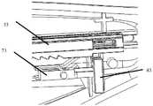
图3为本发明一实施例中吻合器的结构示意图(复位前状态并通过复位开关进行复位操 作);请参阅图3,在本发明的一实施例中,击发齿条组件3包括齿条33。复位机构包括复位 开关7、转动片71、转动片拉簧72。前端执行器4包括夹钳41,切割刀部件42,夹钳弹片 43;夹钳41上的钉仓411既可为固定式钉仓也可为拆卸替换式钉仓。限位组件8包括限位滑 块83、限位滑块扭簧84;转动片拉簧72连接转动片71,限位滑块扭簧84连接限位滑块83。FIG. 3 is a schematic diagram of the structure of the stapler in an embodiment of the present invention (the state before reset and the reset operation is performed by the reset switch); please refer to FIG. 3 , in an embodiment of the present invention, the
在本发明的一实施例中,通过复位开关7进行复位操作,吻合器各组件零件相互作用关 系如下:In an embodiment of the present invention, the reset operation is performed by the
如图3所示,图3中复位开关7为关闭状态,此时,夹钳41处于夹紧状态。当逆时针拨动复位开关7一定角度至复位开启位置,复位开关7与转动片71的左端连动,转动片71顺 时针转动一定角度,转动片71右端将限位滑块83压下后,让开齿条33上对应的限位台阶331,齿条33被施加一回力被拉至复位,中心推杆51也跟随齿条33一起后退,中心推杆51与切 割刀部件42连动,切割刀部件42退至夹钳41后方,切割刀部件42上的挡块结构421不再 压住夹钳41,夹钳41在夹钳弹片43的作用下张开。如图4所示,为复位开关7的启动状态, 夹钳41处于张开状态。其中转动片拉簧82和限位滑块扭簧84为限位组件8提供限位保持力。As shown in FIG. 3 , the
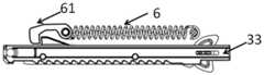
如图13所示,在一实施例中,所述手柄部分还包括回拉组件6。回拉组件6一端连接击 发齿条组件3,另一端固定在外壳相应结构上,能向所述击发组件施加第二方向的回拉力。结 合图3和图13,当逆时针拨动复位开关7一定角度至复位开启位置,转动片71右端将限位滑 块83下压后,让开齿条33上的限位台阶331,齿条33在齿条挡块61的作用下被拉至复位。As shown in FIG. 13 , in one embodiment, the handle portion further includes a pull-
图5为本发明一实施例中吻合器的结构示意图(复位前状态并通过复位帽进行复位操作); 请参阅图5,在本发明的另一实施例中,击发齿条组件3包括复位帽31、复位片32和齿条33, 可通过复位帽31进行复位操作,各组件零件相互作用关系如下:回拉复位帽31,带动复位片 32推开压下限位组件8中的限位滑块83,击发齿条组件3手动拉回复位。Fig. 5 is a schematic diagram of the structure of the stapler in an embodiment of the present invention (the state before reset and the reset operation is performed by the reset cap); please refer to Fig. 5, in another embodiment of the present invention, the
在一实施例中,所述传动件是滑动结构。In one embodiment, the transmission member is a sliding structure.
如图15所示,所述传动件例如为滑动结构73。滑动结构73一端连接复位开关,另一端 连接限位滑块83。拨动复位开关,滑动结构73可沿着预设轨迹滑动。所述滑动结构可以沿着 预设轨迹滑动,例如直线滑动或者曲线滑动。当滑动结构73将限位滑块83向预设方向移动 后,让开齿条33上的限位台阶331,限位滑块83解除对击发组件的限位。As shown in FIG. 15 , the transmission member is, for example, a sliding
在本发明的一实施例中,所述限位组件包括限位滑块、第一弹性件、第一复位开关弹性 件;所述复位机构包括复位开关;所述第一弹性件的第一端连接复位开关,第二端连接限位 滑块,使得第一弹性件能与复位开关、限位滑块双向作用;第一复位开关弹性件一端压在复 位开关上,另一端固定在外壳相应结构上;当拨动复位开关至复位开启位置,复位开关与第 一弹性件的第一端连动,第一弹性件转动设定角度,第一弹性件的第二端将限位滑块向预设 方向拨动,所述限位滑块解除对击发组件的限位。第一复位开关弹性件为复位开关停留于限 位位置提供保持力,第一弹性件还为复位开关停留于在限位位置提供保持力。In an embodiment of the present invention, the limit assembly includes a limit slider, a first elastic member, and a first reset switch elastic member; the reset mechanism includes a reset switch; the first end of the first elastic member The reset switch is connected to the reset switch, and the second end is connected to the limit slider, so that the first elastic member can act in both directions with the reset switch and the limit slider; one end of the elastic member of the first reset switch is pressed on the reset switch, and the other end is fixed on the corresponding structure of the casing When the reset switch is toggled to the reset open position, the reset switch is linked with the first end of the first elastic member, the first elastic member rotates to a set angle, and the second end of the first elastic member pushes the limit slider to the preset position. When the direction is toggled, the limit slider releases the limit on the firing assembly. The first reset switch elastic member provides a retention force for the reset switch to stay at the limit position, and the first elastic member also provides a retention force for the reset switch to stay at the limit position.
图6为本发明一实施例中吻合器限位组件的结构示意图(复位前状态),图7为本发明一 实施例中吻合器限位组件的结构示意图(复位后状态);请参阅图6、图7,在本发明的一实 施例中,限位组件8包括限位滑块83、第一弹性件85、第一复位开关弹性件86;其中第一弹 性件85的左端穿入复位开关7中,右端穿入限位滑块83中,使得第一弹性件85能与复位开 关7、限位滑块83双向作用。第一复位开关弹性件86一端压在复位开关7上,另一端固定在 外壳相应结构上。限位组件8中各组件零件相互作用关系如下:逆时针拨动复位开关7一定 角度至复位开启位置,复位开关7与第一弹性件85的左端连动,第一弹性件85顺时针转动 一定角度,第一弹性件85右端将限位滑块83向下拨动。其中,第一复位开关弹性件86为复 位开关7停留于限位位置提供保持力,第一弹性件85还为复位开关7停留于在限位位置提供 保持力。在一实施例中,第一弹性件85为扭簧,第一复位开关弹性件86为扭簧。FIG. 6 is a schematic structural diagram of the stapler limiting assembly in an embodiment of the present invention (the state before reset), and FIG. 7 is a schematic structural diagram of the stapler limiting assembly in an embodiment of the present invention (the state after resetting); please refer to FIG. 6 7, in an embodiment of the present invention, the
在本发明的一实施例中,所述限位组件包括至少一限位块,所述限位块设置在所述复位 机构上,所述复位机构包括复位开关、第二复位开关弹性件;所述击发组件包括齿条,齿条 设有限位台阶;第二复位开关弹性件的一端作用于复位开关上,另一端固定于外壳相应结构 上;所述限位块卡在齿条的限位台阶处;当拨动复位开关至复位开启位置,复位开关上的限 位块一同向预设方向移动至非限位处,所述限位滑块解除对击发组件的限位。第二复位开关 弹性件为复位开关停留于限位位置提供保持力。In an embodiment of the present invention, the limit assembly includes at least one limit block, and the limit block is disposed on the reset mechanism, and the reset mechanism includes a reset switch and a second reset switch elastic member; so The firing assembly includes a rack, and the rack is provided with a limit step; one end of the second reset switch elastic member acts on the reset switch, and the other end is fixed on the corresponding structure of the casing; the limit block is clamped on the limit step of the rack when the reset switch is toggled to the reset open position, the limit blocks on the reset switch move together in a preset direction to the non-limit position, and the limit slider releases the limit on the firing assembly. The elastic member of the second reset switch provides a holding force for the reset switch to stay at the limit position.
图8为本发明一实施例中吻合器限位组件的结构示意图(复位前状态),图9为本发明一 实施例中吻合器限位组件的结构示意图(复位后状态);FIG. 8 is a schematic structural diagram of the stapler limiting assembly in an embodiment of the present invention (state before reset), and FIG. 9 is a schematic structural diagram of the stapler limiting assembly in an embodiment of the present invention (state after reset);
限位组件为一限位块71,限位块71设置在复位机构上。限位块71与齿条33上限位台阶 331对应设置。复位机构包括复位开关7、第二复位开关弹性件87。第二复位开关弹性件87 一端作用于复位开关7上,另一端固定于外壳相应结构上。如图8所示,限位块71卡在齿条 33的限位台阶331处。向下拨动复位开关7一定距离至复位开启位置,限位结构71一同向下 移动至非限位处,如图9所示。第二复位开关弹性件87为复位开关7停留于限位位置提供保 持力。在一实施例中,第二复位开关弹性件87为压簧。The limit component is a
在本发明的一实施例中,所述限位组件包括至少一限位块,所述限位块设置在所述复位 机构上,所述复位机构包括复位开关、第三复位开关弹性件;所述击发组件包括齿条,齿条 设有限位台阶,限位台阶至少占据横向第一侧的一定宽度;所述限位块卡在齿条的限位台阶 处;当拨动复位开关至复位开启位置,复位开关上的限位块一同向第二侧平移,至完全让开 齿条上的限位台阶。第三复位开关弹性件为复位开关停留于限位位置提供保持力。In an embodiment of the present invention, the limit component includes at least one limit block, the limit block is arranged on the reset mechanism, and the reset mechanism includes a reset switch and a third reset switch elastic member; The firing assembly includes a rack, the rack is provided with a limit step, and the limit step occupies at least a certain width of the lateral first side; the limit block is stuck at the limit step of the rack; when the reset switch is toggled to reset and open position, the limit block on the reset switch moves to the second side together until the limit step on the rack is completely cleared. The third reset switch elastic member provides a holding force for the reset switch to stay at the limit position.
图10至图12为本发明一实施例中吻合器限位组件的结构示意图;请参阅图10至图12, 在本发明的一实施例中,限位组件为一限位块71,限位块71设置在复位机构上。复位机构包 括复位开关7、第三复位开关弹性件88(复位开关7也可以独立于限位组件8而存在);限位 块71与齿条33上限位台阶331对应设置。如图11所示,限位块71卡在齿条33的限位台阶 331处。按下复位开关7至复位开启位置,限位块71一同向右平移(对应上限位块一同向第 二侧平移),至完全让开齿条33上限位台阶331,限位台阶331占据横向左侧的一定宽度(对 应上述限位台阶占据横向第一侧一定宽度),如图12所示。第三复位开关弹性件88为复位开 关7停留于限位位置提供保持力。在一实施例中,第三复位开关弹性件88为压簧。10 to 12 are schematic structural diagrams of the stapler limiting assembly in an embodiment of the present invention; please refer to FIGS. 10 to 12 , in an embodiment of the present invention, the limiting assembly is a limiting
图14为本发明一实施例中吻合器的执行机构的结构示意图。请参阅图14,在本发明的一 实施例中,所述执行器4为再装载器(例如钉匣),可拆卸地与中间连接体5连接。在另一实 施例中,执行器为端部执行器,与中间连接体5连接(图未示)。在一实施例中,钉仓组件可 拆卸地安装于所述执行器的夹钳上。FIG. 14 is a schematic structural diagram of the actuator of the stapler in an embodiment of the present invention. Referring to FIG. 14 , in an embodiment of the present invention, the actuator 4 is a reloader (such as a magazine), which is detachably connected to the intermediate connecting
综上所述,本发明提出的医疗器械,可方便操作者在一只手在握住医疗器械(如吻合器) 的同时还能完成击发齿条的复位动作。To sum up, the medical device proposed by the present invention can facilitate the operator to complete the reset action of the firing rack while holding the medical device (eg, stapler) with one hand.
以上所述实施例的各技术特征可以进行任意的组合,为使描述简洁,未对上述实施例中 的各个技术特征所有可能的组合都进行描述,然而,只要这些技术特征的组合不存在矛盾, 都应当认为是本说明书记载的范围。The technical features of the above-described embodiments can be combined arbitrarily. For the sake of brevity, all possible combinations of the technical features in the above-described embodiments are not described. However, as long as there is no contradiction between the combinations of these technical features, All should be regarded as the scope described in this specification.
这里本发明的描述和应用是说明性的,并非想将本发明的范围限制在上述实施例中。这 里所披露的实施例的变形和改变是可能的,对于那些本领域的普通技术人员来说实施例的替 换和等效的各种部件是公知的。本领域技术人员应该清楚的是,在不脱离本发明的精神或本 质特征的情况下,本发明可以以其它形式、结构、布置、比例,以及用其它组件、材料和部 件来实现。在不脱离本发明范围和精神的情况下,可以对这里所披露的实施例进行其它变形 和改变。The description and application of the present invention herein is illustrative, and is not intended to limit the scope of the present invention to the above-described embodiments. Variations and variations of the embodiments disclosed herein are possible, and alternative and equivalent various components of the embodiments are known to those of ordinary skill in the art. It should be apparent to those skilled in the art that the present invention may be implemented in other forms, structures, arrangements, proportions, and with other components, materials and components without departing from the spirit or essential characteristics of the invention. Other modifications and changes of the embodiments disclosed herein may be made without departing from the scope and spirit of the invention.
Claims (19)
Translated fromChinesePriority Applications (3)
| Application Number | Priority Date | Filing Date | Title |
|---|---|---|---|
| CN201910390807.3ACN111904505A (en) | 2019-05-10 | 2019-05-10 | Medical instrument |
| PCT/CN2020/089155WO2020228600A1 (en) | 2019-05-10 | 2020-05-08 | Medical device |
| US17/609,973US12070209B2 (en) | 2019-05-10 | 2020-05-08 | Medical device |
Applications Claiming Priority (1)
| Application Number | Priority Date | Filing Date | Title |
|---|---|---|---|
| CN201910390807.3ACN111904505A (en) | 2019-05-10 | 2019-05-10 | Medical instrument |
Publications (1)
| Publication Number | Publication Date |
|---|---|
| CN111904505Atrue CN111904505A (en) | 2020-11-10 |
Family
ID=73242303
Family Applications (1)
| Application Number | Title | Priority Date | Filing Date |
|---|---|---|---|
| CN201910390807.3APendingCN111904505A (en) | 2019-05-10 | 2019-05-10 | Medical instrument |
Country Status (3)
| Country | Link |
|---|---|
| US (1) | US12070209B2 (en) |
| CN (1) | CN111904505A (en) |
| WO (1) | WO2020228600A1 (en) |
Cited By (4)
| Publication number | Priority date | Publication date | Assignee | Title |
|---|---|---|---|---|
| CN116262058A (en)* | 2021-12-14 | 2023-06-16 | 天臣国际医疗科技股份有限公司 | Driving mechanism and medical stapler |
| WO2023208235A1 (en)* | 2022-04-29 | 2023-11-02 | 江苏风和医疗器材股份有限公司 | Surgical instrument |
| WO2024017223A1 (en)* | 2022-07-18 | 2024-01-25 | 天臣国际医疗科技股份有限公司 | Firing and switching mechanism and medical stapler |
| CN118593236A (en)* | 2024-06-24 | 2024-09-06 | 昂泰微精医疗科技(上海)有限公司 | A method for zero-point calibration and control of needle insertion of an ophthalmic surgical robot |
Families Citing this family (6)
| Publication number | Priority date | Publication date | Assignee | Title |
|---|---|---|---|---|
| CN109730735B (en)* | 2019-02-21 | 2024-04-12 | 上海逸思医疗科技股份有限公司 | Reduction mechanism, stapler and medical device |
| CN113842184B (en)* | 2021-10-20 | 2022-12-27 | 常州威克医疗器械有限公司 | Triggering safety device for electric endoscope anastomat |
| CN115300024A (en)* | 2022-08-16 | 2022-11-08 | 江苏伟康洁婧医疗器械股份有限公司 | Single-handle pushing and returning mechanism of endoscope anastomat and endoscope anastomat |
| WO2024188140A1 (en)* | 2023-03-10 | 2024-09-19 | 天臣国际医疗科技股份有限公司 | Surgical instrument |
| USD1092737S1 (en)* | 2023-11-17 | 2025-09-09 | Alexis Delobaux | Surgical instrument |
| CN118750074B (en)* | 2024-09-06 | 2025-02-07 | 湖南华外医疗科技有限公司 | A nail pushing slider with self-adaptive nail pushing depth, a nail magazine, anastomosis device and a method |
Citations (9)
| Publication number | Priority date | Publication date | Assignee | Title |
|---|---|---|---|---|
| CN1939228A (en)* | 2005-09-29 | 2007-04-04 | 伊西康内外科公司 | Surgical stapling instrument having preloaded firing assistance mechanism |
| CN104352259A (en)* | 2014-11-07 | 2015-02-18 | 常州市康迪医用吻合器有限公司 | Cutting stapler reset by single hand |
| US9084600B1 (en)* | 2012-02-17 | 2015-07-21 | Cardica, Inc. | Anvil-side staple trap |
| CN105796146A (en)* | 2014-12-31 | 2016-07-27 | 苏州天臣国际医疗科技有限公司 | Nail head assembly and endoscope cutting stapling device with same |
| CN206061811U (en)* | 2016-03-17 | 2017-04-05 | 长兴万佳宠物用品有限公司 | House pet grain throwing peashooter |
| CN107714122A (en)* | 2017-11-23 | 2018-02-23 | 马博平 | Stapler with rotary handle and method of use thereof |
| CN207804298U (en)* | 2017-05-09 | 2018-09-04 | 苏州美东汇成精密部件有限公司 | A kind of laparoscope linear cutting anastomat resist-nailed seat deploying device |
| CN208339568U (en)* | 2017-08-08 | 2019-01-08 | 湖南瀚德微创医疗科技有限公司 | A kind of fast disassembly type endoscope minimally invasive operation pincers |
| CN210903169U (en)* | 2019-05-10 | 2020-07-03 | 上海逸思医疗科技有限公司 | Medical instrument |
Family Cites Families (8)
| Publication number | Priority date | Publication date | Assignee | Title |
|---|---|---|---|---|
| GB8800909D0 (en)* | 1988-01-15 | 1988-02-17 | Ethicon Inc | Gas powered surgical stapler |
| US5865361A (en) | 1997-09-23 | 1999-02-02 | United States Surgical Corporation | Surgical stapling apparatus |
| US7967179B2 (en)* | 2009-03-31 | 2011-06-28 | Tyco Healthcare Group Lp | Center cinch and release of buttress material |
| US8833632B2 (en)* | 2011-09-06 | 2014-09-16 | Ethicon Endo-Surgery, Inc. | Firing member displacement system for a stapling instrument |
| US9386984B2 (en)* | 2013-02-08 | 2016-07-12 | Ethicon Endo-Surgery, Llc | Staple cartridge comprising a releasable cover |
| CN204379348U (en) | 2014-12-30 | 2015-06-10 | 苏州天臣国际医疗科技有限公司 | Surgical operating instrument |
| CN105167814A (en) | 2015-08-14 | 2015-12-23 | 上海逸思医疗科技有限公司 | Surgery equipment with one-hand operated safety device and operation method thereof |
| CN208031243U (en)* | 2017-11-23 | 2018-11-02 | 常州市新能源吻合器总厂有限公司 | A kind of stapler with rotating handle |
- 2019
- 2019-05-10CNCN201910390807.3Apatent/CN111904505A/enactivePending
- 2020
- 2020-05-08USUS17/609,973patent/US12070209B2/enactiveActive
- 2020-05-08WOPCT/CN2020/089155patent/WO2020228600A1/ennot_activeCeased
Patent Citations (9)
| Publication number | Priority date | Publication date | Assignee | Title |
|---|---|---|---|---|
| CN1939228A (en)* | 2005-09-29 | 2007-04-04 | 伊西康内外科公司 | Surgical stapling instrument having preloaded firing assistance mechanism |
| US9084600B1 (en)* | 2012-02-17 | 2015-07-21 | Cardica, Inc. | Anvil-side staple trap |
| CN104352259A (en)* | 2014-11-07 | 2015-02-18 | 常州市康迪医用吻合器有限公司 | Cutting stapler reset by single hand |
| CN105796146A (en)* | 2014-12-31 | 2016-07-27 | 苏州天臣国际医疗科技有限公司 | Nail head assembly and endoscope cutting stapling device with same |
| CN206061811U (en)* | 2016-03-17 | 2017-04-05 | 长兴万佳宠物用品有限公司 | House pet grain throwing peashooter |
| CN207804298U (en)* | 2017-05-09 | 2018-09-04 | 苏州美东汇成精密部件有限公司 | A kind of laparoscope linear cutting anastomat resist-nailed seat deploying device |
| CN208339568U (en)* | 2017-08-08 | 2019-01-08 | 湖南瀚德微创医疗科技有限公司 | A kind of fast disassembly type endoscope minimally invasive operation pincers |
| CN107714122A (en)* | 2017-11-23 | 2018-02-23 | 马博平 | Stapler with rotary handle and method of use thereof |
| CN210903169U (en)* | 2019-05-10 | 2020-07-03 | 上海逸思医疗科技有限公司 | Medical instrument |
Cited By (4)
| Publication number | Priority date | Publication date | Assignee | Title |
|---|---|---|---|---|
| CN116262058A (en)* | 2021-12-14 | 2023-06-16 | 天臣国际医疗科技股份有限公司 | Driving mechanism and medical stapler |
| WO2023208235A1 (en)* | 2022-04-29 | 2023-11-02 | 江苏风和医疗器材股份有限公司 | Surgical instrument |
| WO2024017223A1 (en)* | 2022-07-18 | 2024-01-25 | 天臣国际医疗科技股份有限公司 | Firing and switching mechanism and medical stapler |
| CN118593236A (en)* | 2024-06-24 | 2024-09-06 | 昂泰微精医疗科技(上海)有限公司 | A method for zero-point calibration and control of needle insertion of an ophthalmic surgical robot |
Also Published As
| Publication number | Publication date |
|---|---|
| US20220218343A1 (en) | 2022-07-14 |
| US12070209B2 (en) | 2024-08-27 |
| WO2020228600A1 (en) | 2020-11-19 |
Similar Documents
| Publication | Publication Date | Title |
|---|---|---|
| CN111904505A (en) | Medical instrument | |
| US11882987B2 (en) | Articulating surgical stapling instrument incorporating a two-piece E-beam firing mechanism | |
| CN103767751B (en) | A kind of surgical instruments of one-hand operation | |
| JP5432583B2 (en) | Surgical instrument capable of continuous clamping and cutting | |
| US8096459B2 (en) | Surgical stapler with an end effector support | |
| CN104997541A (en) | One-hand operable surgical instrument and operation method thereof | |
| CN1957854B (en) | Lockout mechanism and surgical instruments including same | |
| CN105167814A (en) | Surgery equipment with one-hand operated safety device and operation method thereof | |
| CN103767752B (en) | A kind of surgical instruments of safety one-hand operation | |
| CN210903169U (en) | Medical instrument | |
| CN205307029U (en) | Surgical instrument capable of being operated by signal hand | |
| JP7441842B2 (en) | trigger mechanism and stapler | |
| CN116549039A (en) | surgical instruments | |
| CN103829987B (en) | Can the straight cuts closer of disposable closed intestinal tube under the mirror of chamber | |
| CN104434241B (en) | End effector, surgical operating instrument and purse-string forceps | |
| CN112089464B (en) | Jaw opening and closing device of laparoscopic stapler | |
| CN102138815B (en) | Suture device for surgical operation | |
| CN118267027B (en) | Drive structure for surgical stapling instrument and surgical stapling instrument | |
| CN102138814B (en) | Surgical stapling instrument | |
| CN118845133A (en) | Clip Applier | |
| CN119679469A (en) | Clip Applier |
Legal Events
| Date | Code | Title | Description |
|---|---|---|---|
| PB01 | Publication | ||
| PB01 | Publication | ||
| SE01 | Entry into force of request for substantive examination | ||
| SE01 | Entry into force of request for substantive examination | ||
| CB02 | Change of applicant information | Address after:Block A, 199 Lane 1, Tianxiong Road, Pudong New Area, Shanghai, 201318 Applicant after:Shanghai Yisi Medical Technology Co.,Ltd. Address before:Block A, 199 Lane 1, Tianxiong Road, Pudong New Area, Shanghai, 201318 Applicant before:SHANGHAI YISI MEDICAL TECHNOLOGY Co.,Ltd. | |
| CB02 | Change of applicant information |