CN111902203B - Zeolite membrane composite, method for producing zeolite membrane composite, and separation method - Google Patents
Zeolite membrane composite, method for producing zeolite membrane composite, and separation methodDownload PDFInfo
- Publication number
- CN111902203B CN111902203BCN201980006596.7ACN201980006596ACN111902203BCN 111902203 BCN111902203 BCN 111902203BCN 201980006596 ACN201980006596 ACN 201980006596ACN 111902203 BCN111902203 BCN 111902203B
- Authority
- CN
- China
- Prior art keywords
- zeolite
- zeolite membrane
- grain boundary
- boundary phase
- phase
- Prior art date
- Legal status (The legal status is an assumption and is not a legal conclusion. Google has not performed a legal analysis and makes no representation as to the accuracy of the status listed.)
- Active
Links
Images


Classifications
- B—PERFORMING OPERATIONS; TRANSPORTING
- B01—PHYSICAL OR CHEMICAL PROCESSES OR APPARATUS IN GENERAL
- B01D—SEPARATION
- B01D53/00—Separation of gases or vapours; Recovering vapours of volatile solvents from gases; Chemical or biological purification of waste gases, e.g. engine exhaust gases, smoke, fumes, flue gases, aerosols
- B01D53/22—Separation of gases or vapours; Recovering vapours of volatile solvents from gases; Chemical or biological purification of waste gases, e.g. engine exhaust gases, smoke, fumes, flue gases, aerosols by diffusion
- B01D53/228—Separation of gases or vapours; Recovering vapours of volatile solvents from gases; Chemical or biological purification of waste gases, e.g. engine exhaust gases, smoke, fumes, flue gases, aerosols by diffusion characterised by specific membranes
- B—PERFORMING OPERATIONS; TRANSPORTING
- B01—PHYSICAL OR CHEMICAL PROCESSES OR APPARATUS IN GENERAL
- B01D—SEPARATION
- B01D67/00—Processes specially adapted for manufacturing semi-permeable membranes for separation processes or apparatus
- B01D67/0039—Inorganic membrane manufacture
- B01D67/0051—Inorganic membrane manufacture by controlled crystallisation, e,.g. hydrothermal growth
- B—PERFORMING OPERATIONS; TRANSPORTING
- B01—PHYSICAL OR CHEMICAL PROCESSES OR APPARATUS IN GENERAL
- B01D—SEPARATION
- B01D69/00—Semi-permeable membranes for separation processes or apparatus characterised by their form, structure or properties; Manufacturing processes specially adapted therefor
- B01D69/02—Semi-permeable membranes for separation processes or apparatus characterised by their form, structure or properties; Manufacturing processes specially adapted therefor characterised by their properties
- B—PERFORMING OPERATIONS; TRANSPORTING
- B01—PHYSICAL OR CHEMICAL PROCESSES OR APPARATUS IN GENERAL
- B01D—SEPARATION
- B01D69/00—Semi-permeable membranes for separation processes or apparatus characterised by their form, structure or properties; Manufacturing processes specially adapted therefor
- B01D69/10—Supported membranes; Membrane supports
- B01D69/105—Support pretreatment
- B—PERFORMING OPERATIONS; TRANSPORTING
- B01—PHYSICAL OR CHEMICAL PROCESSES OR APPARATUS IN GENERAL
- B01D—SEPARATION
- B01D69/00—Semi-permeable membranes for separation processes or apparatus characterised by their form, structure or properties; Manufacturing processes specially adapted therefor
- B01D69/10—Supported membranes; Membrane supports
- B01D69/108—Inorganic support material
- B—PERFORMING OPERATIONS; TRANSPORTING
- B01—PHYSICAL OR CHEMICAL PROCESSES OR APPARATUS IN GENERAL
- B01D—SEPARATION
- B01D69/00—Semi-permeable membranes for separation processes or apparatus characterised by their form, structure or properties; Manufacturing processes specially adapted therefor
- B01D69/12—Composite membranes; Ultra-thin membranes
- B01D69/1218—Layers having the same chemical composition, but different properties, e.g. pore size, molecular weight or porosity
- B—PERFORMING OPERATIONS; TRANSPORTING
- B01—PHYSICAL OR CHEMICAL PROCESSES OR APPARATUS IN GENERAL
- B01D—SEPARATION
- B01D71/00—Semi-permeable membranes for separation processes or apparatus characterised by the material; Manufacturing processes specially adapted therefor
- B01D71/02—Inorganic material
- B01D71/028—Molecular sieves
- B01D71/0281—Zeolites
- C—CHEMISTRY; METALLURGY
- C01—INORGANIC CHEMISTRY
- C01B—NON-METALLIC ELEMENTS; COMPOUNDS THEREOF; METALLOIDS OR COMPOUNDS THEREOF NOT COVERED BY SUBCLASS C01C
- C01B39/00—Compounds having molecular sieve and base-exchange properties, e.g. crystalline zeolites; Their preparation; After-treatment, e.g. ion-exchange or dealumination
- C01B39/02—Crystalline aluminosilicate zeolites; Isomorphous compounds thereof; Direct preparation thereof; Preparation thereof starting from a reaction mixture containing a crystalline zeolite of another type, or from preformed reactants; After-treatment thereof
- C01B39/46—Other types characterised by their X-ray diffraction pattern and their defined composition
- C01B39/48—Other types characterised by their X-ray diffraction pattern and their defined composition using at least one organic template directing agent
- B—PERFORMING OPERATIONS; TRANSPORTING
- B01—PHYSICAL OR CHEMICAL PROCESSES OR APPARATUS IN GENERAL
- B01D—SEPARATION
- B01D2253/00—Adsorbents used in seperation treatment of gases and vapours
- B01D2253/10—Inorganic adsorbents
- B01D2253/106—Silica or silicates
- B01D2253/108—Zeolites
- B—PERFORMING OPERATIONS; TRANSPORTING
- B01—PHYSICAL OR CHEMICAL PROCESSES OR APPARATUS IN GENERAL
- B01D—SEPARATION
- B01D2323/00—Details relating to membrane preparation
- B01D2323/24—Use of template or surface directing agents [SDA]
- B—PERFORMING OPERATIONS; TRANSPORTING
- B01—PHYSICAL OR CHEMICAL PROCESSES OR APPARATUS IN GENERAL
- B01D—SEPARATION
- B01D2325/00—Details relating to properties of membranes
- B01D2325/02—Details relating to pores or porosity of the membranes
- B01D2325/022—Asymmetric membranes
- B—PERFORMING OPERATIONS; TRANSPORTING
- B01—PHYSICAL OR CHEMICAL PROCESSES OR APPARATUS IN GENERAL
- B01D—SEPARATION
- B01D2325/00—Details relating to properties of membranes
- B01D2325/02—Details relating to pores or porosity of the membranes
- B01D2325/022—Asymmetric membranes
- B01D2325/0233—Asymmetric membranes with clearly distinguishable layers
- B—PERFORMING OPERATIONS; TRANSPORTING
- B82—NANOTECHNOLOGY
- B82Y—SPECIFIC USES OR APPLICATIONS OF NANOSTRUCTURES; MEASUREMENT OR ANALYSIS OF NANOSTRUCTURES; MANUFACTURE OR TREATMENT OF NANOSTRUCTURES
- B82Y30/00—Nanotechnology for materials or surface science, e.g. nanocomposites
Landscapes
- Chemical & Material Sciences (AREA)
- Chemical Kinetics & Catalysis (AREA)
- Inorganic Chemistry (AREA)
- Engineering & Computer Science (AREA)
- Geology (AREA)
- Life Sciences & Earth Sciences (AREA)
- Analytical Chemistry (AREA)
- Manufacturing & Machinery (AREA)
- Crystallography & Structural Chemistry (AREA)
- General Chemical & Material Sciences (AREA)
- Oil, Petroleum & Natural Gas (AREA)
- General Life Sciences & Earth Sciences (AREA)
- Organic Chemistry (AREA)
- Materials Engineering (AREA)
- Separation Using Semi-Permeable Membranes (AREA)
- Silicates, Zeolites, And Molecular Sieves (AREA)
Abstract
Description
Translated fromChinese技术领域technical field
本发明涉及沸石膜复合体、沸石膜复合体的制造方法以及使用了沸石膜复合体的混合物质的分离方法。The present invention relates to a zeolite membrane composite, a method for producing the zeolite membrane composite, and a method for separating a mixed substance using the zeolite membrane composite.
背景技术Background technique
目前,对于在支撑体上形成沸石膜、制成沸石膜复合体、从而利用沸石的分子筛作用进行特定分子的分离及分子的吸附等用途,进行了各种研究及开发。At present, various researches and development have been carried out for applications such as forming a zeolite membrane on a support and forming a zeolite membrane complex, thereby utilizing the molecular sieve action of zeolite to perform separation of specific molecules and adsorption of molecules.
在日本特许第3922389号公报(文献1)中记载:关于沸石膜的沸石晶体间的晶界,为了使沸石膜显示出优异的分子筛作用,在晶界没有形成直径比沸石的细孔大的孔是非常重要的。该沸石膜的晶界为密度比沸石晶体的密度大的氧化物。In Japanese Patent No. 3922389 (Document 1), it is described that, regarding the grain boundaries between zeolite crystals in the zeolite membrane, in order for the zeolite membrane to exhibit an excellent molecular sieve effect, no pores larger in diameter than the pores of the zeolite are formed in the grain boundaries. is very important. The grain boundaries of the zeolite membrane are oxides whose density is higher than that of the zeolite crystals.
在日本特许第2981884号公报(文献2)中公开如下技术,即,将沸石膜的原料分为2种液体,将这些原料液从多孔质体的两侧向细孔内填充,在细孔内形成2种液体的界面,通过水热合成在细孔内形成沸石膜。在这种情况下,由于使沸石晶体在多孔质体的细孔内析出,所以,形成非常小的晶体即可,从而形成缺陷少的具有高分离性能的沸石膜。Japanese Patent No. 2981884 (Document 2) discloses a technique in which a raw material for a zeolite membrane is divided into two types of liquids, these raw material liquids are filled into pores from both sides of a porous body, and the pores are filled with liquids. An interface between two liquids is formed, and a zeolite membrane is formed in the pores by hydrothermal synthesis. In this case, since the zeolite crystals are precipitated in the pores of the porous body, it is sufficient to form very small crystals, thereby forming a zeolite membrane with few defects and high separation performance.
在日本特开2002-263457号公报(文献3)中公开如下技术,即,使偶联剂与沸石膜的一面接触,使水或水蒸汽与另一面接触,由此对沸石膜的晶界相的空隙、龟裂以及针孔选择性地进行补修。Japanese Patent Application Laid-Open No. 2002-263457 (Document 3) discloses a technique in which a coupling agent is brought into contact with one surface of a zeolite membrane, and water or steam is brought into contact with the other surface, whereby the grain boundary phase of the zeolite membrane is affected. The voids, cracks and pinholes are selectively repaired.
日本特开2002-348579号公报(文献4)的沸石膜具有沸石晶体固有的细孔,并且,在晶体晶界具有细孔。该晶体晶界的细孔径大于沸石晶体固有的细孔径,且为10nm以下。利用该沸石膜,将烃混合物效率良好地分离为富含直链烃的成分和富含支链烃的成分。The zeolite membrane of Japanese Patent Application Laid-Open No. 2002-348579 (Document 4) has pores inherent to zeolite crystals and has pores in crystal grain boundaries. The pore diameter of the crystal grain boundary is larger than the pore diameter inherent to the zeolite crystal, and is 10 nm or less. With this zeolite membrane, the hydrocarbon mixture is efficiently separated into a straight-chain hydrocarbon-rich component and a branched-chain hydrocarbon-rich component.
但是,在将沸石膜实际用于分子分离或分子吸附等的情况下,还要求具有高渗透性能及分离性能、以及使用环境下的高耐久性。然后,虽然研究了晶界相对沸石膜的暂时渗透性能的影响,但是,没有研究晶界相对沸石膜的耐久性的影响。However, when a zeolite membrane is actually used for molecular separation, molecular adsorption, or the like, it is also required to have high permeation performance and separation performance, and high durability in a use environment. Then, although the influence of the grain boundary on the temporary permeability of the zeolite membrane was studied, the influence of the grain boundary on the durability of the zeolite membrane was not studied.
发明内容SUMMARY OF THE INVENTION
本发明的目的在于,实现沸石膜的高渗透性能及分离性能、以及高耐久性。An object of the present invention is to achieve high permeation performance, separation performance, and high durability of a zeolite membrane.
本发明适用于沸石膜复合体。本发明的优选的一个方案所涉及的沸石膜复合体具备:多孔质的支撑体、以及形成在所述支撑体上的沸石膜。所述沸石膜具备:沸石晶相,该沸石晶相由多个沸石晶体构成;以及致密的晶界相,该晶界相为所述多个沸石晶体之间的区域。所述晶界相的至少一部分的密度小于所述沸石晶相的密度。所述晶界相的宽度为2nm以上且10nm以下。根据本发明,能够实现沸石膜的高渗透性能及分离性能、以及高耐久性。The present invention is applicable to zeolite membrane composites. The zeolite membrane complex according to a preferred aspect of the present invention includes a porous support and a zeolite membrane formed on the support. The zeolite membrane includes: a zeolite crystal phase composed of a plurality of zeolite crystals; and a dense grain boundary phase that is a region between the plurality of zeolite crystals. The density of at least a portion of the grain boundary phase is less than the density of the zeolite crystal phase. The width of the grain boundary phase is 2 nm or more and 10 nm or less. According to the present invention, high permeation performance and separation performance, and high durability of the zeolite membrane can be achieved.
优选为,所述晶界相的宽度为所述沸石晶相中包含的沸石晶体的细孔径的5倍以上且27倍以下。Preferably, the width of the grain boundary phase is 5 times or more and 27 times or less the pore diameter of the zeolite crystals contained in the zeolite crystal phase.
优选为,所述晶界相的宽度为所述沸石膜中的沸石粒子的平均粒径的0.005倍以上且0.12倍以下。Preferably, the width of the grain boundary phase is 0.005 times or more and 0.12 times or less the average particle diameter of the zeolite particles in the zeolite membrane.
优选为,所述晶界相由无机物形成。Preferably, the grain boundary phase is formed of an inorganic substance.
优选为,所述晶界相包含非晶质。Preferably, the grain boundary phase contains amorphous.
优选为,所述晶界相中密度比所述沸石晶相的密度小的部分的面积为所述晶界相整体的面积的10%以上。Preferably, the area of a portion of the grain boundary phase having a density smaller than that of the zeolite crystal phase is 10% or more of the entire area of the grain boundary phase.
本发明还适用于沸石膜复合体的制造方法。本发明的优选的一个方案所涉及的沸石膜复合体的制造方法包括以下工序:a)准备晶种的工序,b)使所述晶种附着于多孔质的支撑体上的工序,以及c)将所述支撑体浸渍于原料溶液中,通过水热合成使沸石自所述晶种生长而在所述支撑体上形成沸石膜的工序。所述沸石膜具备:沸石晶相,该沸石晶相由多个沸石晶体构成;以及致密的晶界相,该晶界相为所述多个沸石晶体之间的区域。所述晶界相的至少一部分的密度小于所述沸石晶相的密度。所述晶界相的宽度为2nm以上且10nm以下。根据本发明,能够实现沸石膜的高渗透性能及分离性能、以及高耐久性。The present invention is also applicable to a method for producing a zeolite membrane composite. A method for producing a zeolite membrane composite according to a preferred aspect of the present invention includes the following steps: a) a step of preparing a seed crystal, b) a step of attaching the seed crystal to a porous support, and c) A step in which the support is immersed in a raw material solution, and zeolite is grown from the seed crystal by hydrothermal synthesis to form a zeolite membrane on the support. The zeolite membrane includes: a zeolite crystal phase composed of a plurality of zeolite crystals; and a dense grain boundary phase that is a region between the plurality of zeolite crystals. The density of at least a portion of the grain boundary phase is less than the density of the zeolite crystal phase. The width of the grain boundary phase is 2 nm or more and 10 nm or less. According to the present invention, high permeation performance and separation performance, and high durability of the zeolite membrane can be achieved.
优选为,所述c)工序中,所述原料溶液的溶剂不含除了结构导向剂以外的胺。Preferably, in the step c), the solvent of the raw material solution does not contain amines other than the structure directing agent.
优选为,所述c)工序中,所述原料溶液的溶剂包含醇。Preferably, in the step c), the solvent of the raw material solution contains alcohol.
本发明还适用于分离方法。本发明的优选的一个方案所涉及的分离方法包括如下工序:a)准备上述沸石膜复合体的工序、以及b)向所述沸石膜复合体供给包含多种气体或液体的混合物质,使所述混合物质中的渗透性高的物质透过所述沸石膜复合体,由此使该物质从其他物质中分离出来的工序。The present invention is also applicable to separation methods. A separation method according to a preferred aspect of the present invention includes the steps of: a) preparing the zeolite membrane composite, and b) supplying a mixed substance containing a plurality of gases or liquids to the zeolite membrane composite, so that the zeolite membrane composite is A process in which a highly permeable substance in the mixed substance permeates the zeolite membrane complex, thereby separating the substance from other substances.
优选为,所述混合物质包含氢、氦、氮、氧、水、水蒸汽、一氧化碳、二氧化碳、氮氧化物、氨、硫氧化物、硫化氢、氟化硫、汞、胂、氰化氢、羰基硫、C1~C8的烃、有机酸、醇、硫醇类、酯、醚、酮以及醛中的1种以上的物质。Preferably, the mixed substance comprises hydrogen, helium, nitrogen, oxygen, water, water vapor, carbon monoxide, carbon dioxide, nitrogen oxides, ammonia, sulfur oxides, hydrogen sulfide, sulfur fluoride, mercury, arsine, hydrogen cyanide, One or more substances selected from carbonyl sulfide, C1-C8 hydrocarbons, organic acids, alcohols, thiols, esters, ethers, ketones and aldehydes.
上述的目的及其他目的、特征、方案以及优点通过以下参照附图进行的本发明的详细说明加以明确。The above-mentioned object and other objects, features, means, and advantages will be clarified by the following detailed description of the present invention with reference to the accompanying drawings.
附图说明Description of drawings
图1是沸石膜复合体的截面图。FIG. 1 is a cross-sectional view of a zeolite membrane composite.
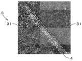
图2是沸石膜的放大图。Figure 2 is an enlarged view of the zeolite membrane.
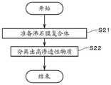
图3是表示沸石膜复合体的制造流程的图。FIG. 3 is a diagram showing a production flow of the zeolite membrane composite.
图4是表示分离装置的图。FIG. 4 is a diagram showing a separation device.
图5是表示混合物质的分离流程的图。FIG. 5 is a diagram showing a separation flow of a mixed substance.
具体实施方式Detailed ways
图1是本发明的一个实施方式所涉及的沸石膜复合体1的截面图。沸石膜复合体1具备:支撑体11、以及形成在支撑体11上的沸石膜12。图1所示的例子中,支撑体11是设置有分别在长度方向(即,图中的上下方向)上延伸的多个贯通孔111的大致圆柱状的整体型支撑体。各贯通孔111(即,隔室)的与长度方向垂直的截面为例如大致圆形。图1中,比实际大地描画贯通孔111的直径,比实际少地描画贯通孔111的数量。沸石膜12形成在贯通孔111的内侧面上,将贯通孔111的内侧面在大致整面上进行被覆。图1中,以粗线描画沸石膜12。FIG. 1 is a cross-sectional view of a
支撑体11的长度(即,图中的上下方向的长度)为例如10cm~200cm。支撑体11的外径为例如0.5cm~30cm。相邻的贯通孔111的中心轴间的距离为例如0.3mm~10mm。支撑体11的表面粗糙度(Ra)为例如0.1μm~5.0μm,优选为0.2μm~2.0μm。应予说明,支撑体11的形状可以为例如蜂窝状、平板状、管状、圆筒状、圆柱状或多棱柱状等。在支撑体11的形状为管状的情况下,支撑体11的厚度为例如0.1mm~10mm。The length of the support body 11 (that is, the length in the vertical direction in the figure) is, for example, 10 cm to 200 cm. The outer diameter of the
本实施方式中,支撑体11为气体或液体(即,流体)能够透过的多孔质,沸石膜12为利用分子筛作用从混有多种物质的混合流体中分离出特定物质的分子分离膜。例如,沸石膜12可以用作从包含多种气体的混合气体中分离出特定气体的气体分离膜。另外,沸石膜12可以用作从包含多种液体的混合液中分离出特定液体的液体分离膜。沸石膜12可以用作从气体和液体混合得到的混合流体中分离出特定物质的分离膜。或者,沸石膜12还可以用作渗透气化膜。沸石膜复合体1还可以用于其他用途。In the present embodiment, the
支撑体11的材料在将沸石膜12形成于表面的工序中具有化学稳定性即可,可以采用各种材料。作为支撑体11的材料,例如可以举出:陶瓷烧结体、金属、有机高分子、玻璃、碳等。作为陶瓷烧结体,可以举出:氧化铝、二氧化硅、多铝红柱石、二氧化锆、二氧化钛、三氧化二钇、氮化硅、碳化硅等。作为金属,可以举出:铝、铁、青铜、不锈钢等。作为有机高分子,可以举出:聚乙烯、聚丙烯、聚四氟乙烯、聚砜、聚酰亚胺等。本实施方式中,支撑体11包含氧化铝、二氧化硅以及多铝红柱石中的至少1种。The material of the
支撑体11可以包含无机粘结材料。作为无机粘结材料,可以使用二氧化钛、多铝红柱石、易烧结性氧化铝、二氧化硅、玻璃料、粘土矿物、易烧结性堇青石中的至少1种。The
在沸石膜12用作分离膜的情况下,优选为,形成沸石膜12的表面附近的支撑体11的平均细孔径小于其他部位的平均细孔径。为了实现上述结构,支撑体11具有多层结构。在支撑体11具有多层结构的情况下,各层的材料可以使用上述的材料,可以分别相同,也可以不同。支撑体11的平均细孔径可以通过压汞仪、细孔径分布测定器、纳米尺寸细孔径分布测定器等来测定。When the
支撑体11的平均细孔径为例如0.01μm~70μm,优选为0.05μm~25μm。形成沸石膜12的表面附近的支撑体11的平均细孔径为0.01μm~1μm,优选为0.05μm~0.5μm。平均细孔径可以通过例如压汞仪、孔径分析仪或纳米孔径分析仪来测定。关于支撑体11的包括表面及内部在内的整体的细孔径的分布,D5为例如0.01μm~50μm,D50为例如0.05μm~70μm,D95为例如0.1μm~2000μm。形成沸石膜12的表面附近的支撑体11的气孔率为例如20%~60%。The average pore diameter of the
支撑体11具有例如平均细孔径不同的多个层在厚度方向上层叠而成的多层结构。包括形成沸石膜12的表面在内的表面层中的平均细孔径及烧结粒径小于表面层以外的层中的平均细孔径及烧结粒径。支撑体11的表面层的平均细孔径为例如0.01μm~1μm,优选为0.05μm~0.5μm。在支撑体11具有多层结构的情况下,各层的材料可以使用上述的材料。形成多层结构的多个层的材料可以相同,也可以不同。The
沸石膜12的厚度为例如0.05μm~30μm,优选为0.1μm~20μm,更优选为0.5μm~10μm。如果沸石膜12变厚,则分离性能提高。如果沸石膜12变薄,则渗透速度增大。沸石膜12的表面粗糙度(Ra)为例如5μm以下,优选为2μm以下,更优选为1μm以下,进一步优选为0.5μm以下。The thickness of the
图2是利用透射型电子显微镜(TEM:Transmission Electron Microscope)观察将沸石膜12研磨而形成的研磨面得到的放大图。图2中图示沸石膜12的研磨面的一部分。如图2所示,沸石膜12具备:沸石晶相3,其由多个沸石晶体31构成;以及晶界相4,其为该多个沸石晶体31之间的区域。图2中,以虚线表示沸石晶体31与晶界相4之间的分界的大概位置。FIG. 2 is an enlarged view obtained by observing the polished surface formed by polishing the
沸石晶体31的种类没有特别限定,在沸石膜12用作分离膜的情况下,从渗透物质的渗透量及分离性能的观点考虑,优选沸石晶体31的环的最大员数为6或8。更优选沸石晶体31的环的最大员数为8。The type of the
沸石晶体31为例如DDR型的沸石。换言之,沸石晶体31为国际沸石学会规定的结构编码为“DDR”的沸石。沸石晶体31不限定于DDR型的沸石,可以为具有其他结构的沸石。沸石晶体31可以为例如AEI型、AEN型、AFN型、AFV型、AFX型、BEA型、CHA型、DDR型、ERI型、ETL型、FAU型(X型、Y型)、GIS型、LEV型、LTA型、MEL型、MFI型、MOR型、PAU型、RHO型、SAT型、SOD型等的沸石。更优选为例如AEI型、AFN型、AFV型、AFX型、CHA型、DDR型、ERI型、ETL型、GIS型、LEV型、LTA型、PAU型、RHO型、SAT型等的沸石。进一步优选为例如AEI型、AFN型、AFV型、AFX型、CHA型、DDR型、ERI型、ETL型、GIS型、LEV型、PAU型、RHO型、SAT型等的沸石。The
构成沸石膜12的沸石中,作为T原子,包含例如Al。作为构成沸石膜12的沸石,可以使用位于构成沸石的氧四面体(TO4)的中心的原子(T原子)包含硅(Si)和铝(Al)的沸石、T原子包含Al和磷(P)的AlPO型的沸石、T原子包含Si、Al及P的SAPO型的沸石、T原子包含镁(Mg)、Si、Al及P的MAPSO型的沸石、T原子包含锌(Zn)、Si、Al及P的ZnAPSO型的沸石等。T原子的一部分可以置换为其他元素。The zeolite constituting the
沸石膜12包含例如Si。沸石膜12可以包含例如Si、Al以及P中的任意2种以上。沸石膜12还可以包含碱金属。该碱金属为例如钠(Na)或钾(K)。在沸石膜12包含Si原子的情况下,沸石膜12中的Si/Al比为例如1以上且10万以下。该Si/Al比优选为5以上,更优选为20以上,进一步优选为100以上,越高越理想。可以通过调整后述原料溶液中的Si源与Al源的配合比例等来调整沸石膜12中的Si/Al比。The
沸石膜12中,沸石晶体31的固有细孔径为例如0.36nm×0.44nm,平均细孔径为0.40nm。沸石晶体31的固有细孔径小于支撑体11的细孔径。In the
晶界相4为包含非晶质(即,无定形)和/或沸石晶体31以外的晶体的相。优选为,晶界相4包含非晶质。更优选为,晶界相4包含10重量%以上的非晶质。另外,晶界相4优选由无机物形成。换言之,晶界相4优选仅由无机物形成,实质上不含有机物。实质上不含有机物是指:不含5重量%以上的有机物。The
晶界相4为致密的相。该致密的相是指:实质上不具有孔径大于沸石晶体31的细孔径的细孔的相。沸石晶体31的细孔径是指:沸石晶体31的固有细孔径的长径与短径的平均值。The
晶界相4的宽度为2nm~10nm,优选为2nm~8nm,更优选为2nm~6nm。晶界相4的宽度如下求解。首先,利用TEM观察沸石膜12的研磨面,注目于1个沸石晶体31。接下来,在所注目的沸石晶体31(以下称为“注目沸石晶体31”。)的周缘,测定注目沸石晶体31和与注目沸石晶体31相邻的沸石晶体31之间的距离(以下称为“晶体间距离”。)。晶体间距离是:注目沸石晶体31与相邻沸石晶体31之间的区域(图2中、沸石晶体31间的浓度低的区域)中宽度最大的部分的宽度。对于1个注目沸石晶体31,利用注目沸石晶体31的长轴和短轴将其周缘分为四份,对分割出的4个周缘分别测定1处晶体间距离,将该4个晶体间距离的平均值作为注目沸石晶体31的平均晶体间距离。例如,在TEM图像上的注目沸石晶体31为大致矩形的情况下,该4处分别位于注目沸石晶体31的4个边上。然后,取得将10个沸石晶体31分别作为注目沸石晶体31时的平均晶体间距离,将10个平均晶体间距离的平均值作为晶界相4的宽度。The width of the
晶界相4的宽度优选为沸石晶体31的上述细孔径(即,固有细孔径的长径与短径的平均值)的5倍~27倍。晶界相4的宽度更优选为沸石晶体31的细孔径的5倍~20倍,进一步优选为沸石晶体31的细孔径的5倍~15倍。The width of the
晶界相4的宽度优选为沸石膜12中的沸石粒子的平均粒径的0.005倍~0.12倍。晶界相4的宽度更优选为沸石粒子的平均粒径的0.005倍~0.045倍,进一步优选为0.005倍~0.02倍。沸石膜12中,沸石粒子的平均粒径为90nm~370nm。沸石粒子的平均粒径如下求解,即,利用TEM观察将沸石膜12研磨而形成的研磨面,对任意10个沸石粒子的粒径进行平均,由此求出平均粒径。各沸石粒子的粒径作为该沸石粒子的最大径与最小径的平均值来求解。The width of the
晶界相4的至少一部分的密度小于沸石晶相3的密度。晶界相4中密度比沸石晶相3的密度小的部分(以下称为“低密度部”。)的面积优选为晶界相4整体的面积的10%以上。如果将低密度部的面积相对于晶界相4整体的面积的比例称为“低密度比率”,则低密度比率更优选为20%以上,进一步优选为30%以上。晶界相4的低密度比率的上限没有特别限定,低密度比率典型的为100%以下,更典型的为95%以下。The density of at least a part of the
在沸石膜12的研磨面的TEM图像中,对晶界相4及沸石晶相3的浓淡进行比较,由此取得晶界相4的密度与沸石晶相3的密度之间的大小关系。具体而言,在TEM图像中晶界相4比沸石晶相3浓(即,浓度高)的情况下,晶界相4的密度大于沸石晶相3的密度。另一方面,在TEM图像中晶界相4比沸石晶相3淡(即,浓度低)的情况下,晶界相4的密度小于沸石晶相3的密度。In the TEM image of the polished surface of the
另外,低密度比率如下求解。首先,在沸石膜12的研磨面的TEM图像中,选择任意1个沸石晶体31,并选择包括与所选择的沸石晶体31相邻的所有沸石晶体31之间的晶界相4的区域,以规定的阈值对该区域进行二值化。阈值按能够识别出所选择的沸石晶体31和晶界相4的方式进行适当确定。接下来,基于二值化后的上述区域的图像,分别求出晶界相4中的、浓度小于该阈值的部分的面积和浓度为该阈值以上的部分的面积。即,分别求出晶界相4中的、密度小于沸石晶相3的密度的部分的面积和密度为沸石晶相3的密度以上的部分的面积。然后,采用上述面积,计算出该区域中的低密度比率。本实施方式中,将针对TEM图像上的10个区域分别求出的低密度比率的平均值作为沸石膜12的晶界相4的低密度比率。In addition, the low density ratio is solved as follows. First, in the TEM image of the polished surface of the
接下来,参照图3,对沸石膜复合体1的制造流程进行说明。首先,准备出沸石膜12制造用的晶种(步骤S11)。例如,利用水热合成生成DDR型的沸石的粉末,由该沸石的粉末取得晶种。可以将该沸石的粉末直接用作晶种,也可以通过粉碎等对该粉末进行加工来取得晶种。Next, the production flow of the
接下来,将多孔质的支撑体11浸渍于分散有晶种的溶液中,使晶种附着于支撑体11(步骤S12)。或者,使分散有晶种的溶液与支撑体11上的待形成沸石膜12的部分接触,由此使晶种附着于支撑体11。由此,制作附着有晶种的支撑体。晶种可以利用其他方法附着于支撑体11。Next, the
将附着有晶种的支撑体11浸渍于原料溶液中。使例如Si源、Al源以及结构导向剂(Structure-Directing Agent、以下也称为“SDA”。)等溶解于溶剂中,来制作原料溶液。原料溶液的溶剂优选包含乙醇等醇。另外,该溶剂优选实质上不含除了结构导向剂以外的胺(即,乙二胺等胺)。应予说明,“实质上不含除了结构导向剂以外的胺”是指:除了结构导向剂以外的胺在溶剂中的浓度为0.05mol%以下。原料溶液的组成为例如1.00SiO2:0Al2O3:0.015SDA:0.16CH3CH2OH。作为原料溶液中包含的SDA,例如可以使用1-金刚烷胺。The
然后,利用水热合成以该晶种为核使DDR型的沸石生长,由此在支撑体11上形成DDR型的沸石膜12(步骤S13)。水热合成时的温度优选为120~200℃,例如为160℃。水热合成时间优选为4~100小时,例如为30小时。此时,可以通过对原料溶液中的Si源与Al源之间的配合比例等进行调整来调整DDR型的沸石膜12的组成。Then, the DDR type zeolite is grown using the seed crystal as a nucleus by hydrothermal synthesis, whereby the DDR
当水热合成结束后,将支撑体11及沸石膜12用离子交换水进行清洗。将清洗后的支撑体11及沸石膜12于例如80℃进行干燥。当支撑体11及沸石膜12干燥后,对沸石膜12进行加热处理,由此,将SDA燃烧除去,使沸石膜12内的微细孔贯通(步骤S14)。沸石膜12的加热温度及加热时间为例如450℃及50小时。由此,得到上述的沸石膜复合体1。应予说明,在沸石膜12的制造中不使用SDA的情况下,省略步骤S14中的SDA的燃烧除去。After the hydrothermal synthesis is completed, the
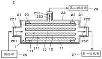
接下来,参照图4及图5,对利用了沸石膜复合体1的混合物质的分离进行说明。图4是表示分离装置2的图。图5是表示利用分离装置2将混合物质分离的分离流程的图。Next, with reference to FIGS. 4 and 5 , the separation of the mixed substances using the
分离装置2中,向沸石膜复合体1供给包含多种流体(即,气体或液体)的混合物质,使混合物质中的渗透性高的物质透过沸石膜复合体1,由此将该物质从其他物质中分离出来。分离装置2中的分离可以是出于例如将渗透性高的物质从混合物质中提取出来的目的而进行的,也可以是出于将渗透性低的物质浓缩的目的而进行的。In the
如上所述,该混合物质(即,混合流体)可以为包含多种气体的混合气体,也可以为包含多种液体的混合液,还可以为同时包含气体及液体的气液二相流体。As described above, the mixed substance (ie, mixed fluid) can be a mixed gas containing multiple gases, a mixed liquid containing multiple liquids, or a gas-liquid two-phase fluid containing both gas and liquid.
分离装置2中,20℃~400℃下的沸石膜复合体1的CO2的渗透量(Permeance)为例如100nmol/m2·s·Pa以上。另外,20℃~400℃下的沸石膜复合体1的CO2的渗透量/CH4泄漏量比(渗透量比,Permeance ratio)为例如100以上。该渗透量及渗透量比为沸石膜复合体1的供给侧与透过侧之间的CO2的分压差为1.5MPa的情况下的结果。In the
混合物质包含例如氢(H2)、氦(He)、氮(N2)、氧(O2)、水(H2O)、水蒸汽(H2O)、一氧化碳(CO)、二氧化碳(CO2)、氮氧化物、氨(NH3)、硫氧化物、硫化氢(H2S)、氟化硫、汞(Hg)、胂(AsH3)、氰化氢(HCN)、羰基硫(COS)、C1~C8的烃、有机酸、醇、硫醇类、酯、醚、酮以及醛中的1种以上的物质。Mixed substances include, for example, hydrogen (H2 ), helium (He), nitrogen (N2 ), oxygen (O2 ), water (H2 O), water vapor (H2 O), carbon monoxide (CO), carbon dioxide (CO)2 ), nitrogen oxides, ammonia (NH3 ), sulfur oxides, hydrogen sulfide (H2 S), sulfur fluoride, mercury (Hg), arsine (AsH3 ), hydrogen cyanide (HCN), carbonyl sulfide ( COS), C1-C8 hydrocarbons, organic acids, alcohols, mercaptans, esters, ethers, ketones, and one or more species of aldehydes.
氮氧化物为氮和氧的化合物。上述的氮氧化物为例如一氧化氮(NO)、二氧化氮(NO2)、氧化亚氮(也称为一氧化二氮。)(N2O)、三氧化二氮(N2O3)、四氧化二氮(N2O4)、五氧化二氮(N2O5)等称为NOX(NOX)的气体。Nitrogen oxides are compounds of nitrogen and oxygen. The above-mentioned nitrogen oxides are, for example, nitric oxide (NO), nitrogen dioxide (NO2 ), nitrous oxide (also referred to as nitrous oxide.) (N2 O), and dinitrogen trioxide (N2 O3 ). ), dinitrogen tetroxide (N2 O4 ), dinitrogen pentoxide (N2 O5 ) and other gases calledNOx (NOX).
硫氧化物为硫和氧的化合物。上述的硫氧化物为例如二氧化硫(SO2)、三氧化硫(SO3)等称为SOX(SOX)的气体。Sulfur oxides are compounds of sulfur and oxygen. The above-mentioned sulfur oxides are, for example, gases called SOX (SOX) such as sulfur dioxide (SO2 ) and sulfur trioxide (SO3 ).
氟化硫为氟和硫的化合物。上述的氟化硫为例如二氟化二硫(F-S-S-F,S=SF2)、二氟化硫(SF2)、四氟化硫(SF4)、六氟化硫(SF6)或十氟化二硫(S2F10)等。Sulfur fluoride is a compound of fluorine and sulfur. The above-mentioned sulfur fluoride is, for example, disulfide difluoride (F-S-S-F, S=SF2 ), sulfur difluoride (SF2 ), sulfur tetrafluoride (SF4 ), sulfur hexafluoride ( SF6 ) or disulfide decafluoride (S2 F10 ), etc.
C1~C8的烃是碳为1个以上且8个以下的烃。C3~C8的烃可以为直链化合物、支链化合物以及环式化合物中的任一者。另外,C3~C8的烃可以为饱和烃(即,分子中不存在双键及三键的烃)、不饱和烃(即,分子中存在双键和/或三键的烃)中的任一者。C1~C4的烃为例如甲烷(CH4)、乙烷(C2H6)、乙烯(C2H4)、丙烷(C3H8)、丙烯(C3H6)、正丁烷(CH3(CH2)2CH3)、异丁烷(CH(CH3)3)、1-丁烯(CH2=CHCH2CH3)、2-丁烯(CH3CH=CHCH3)或异丁烯(CH2=C(CH3)2)。The hydrocarbons of C1 to C8 are hydrocarbons having 1 or more and 8 or less carbons. The hydrocarbon of C3-C8 may be any of a straight chain compound, a branched chain compound, and a cyclic compound. In addition, C3-C8 hydrocarbons may be any of saturated hydrocarbons (that is, hydrocarbons without double bonds and triple bonds in the molecule) and unsaturated hydrocarbons (that is, hydrocarbons with double bonds and/or triple bonds in the molecules). By. C1-C4 hydrocarbons are, for example, methane (CH4 ), ethane (C2 H6 ), ethylene (C2 H4 ), propane (C3 H8 ), propylene (C3 H6 ), n-butane (CH3 (CH2 )2CH3 ), isobutane (CH(CH3 )3 ),1 -butene (CH2=CHCH2CH3 ),2 -butene (CH3CH= CHCH3) or Isobutylene (CH2 =C(CH3 )2 ).
上述的有机酸为羧酸或磺酸等。羧酸为例如甲酸(CH2O2)、乙酸(C2H4O2)、草酸(C2H2O4)、丙烯酸(C3H4O2)或苯甲酸(C6H5COOH)等。磺酸为例如乙磺酸(C2H6O3S)等。该有机酸可以为链式化合物,也可以为环式化合物。The above-mentioned organic acid is a carboxylic acid, a sulfonic acid, or the like. Carboxylic acids are, for example, formic acid (CH2 O2 ), acetic acid (C2 H4 O2 ), oxalic acid (C2 H2 O4 ), acrylic acid (C3 H4 O2 ) or benzoic acid (C6 H5 COOH) )Wait. The sulfonic acid is, for example, ethanesulfonic acid (C2 H6 O3 S) and the like. The organic acid may be a chain compound or a cyclic compound.
上述的醇为例如甲醇(CH3OH)、乙醇(C2H5OH)、异丙醇(2-丙醇)(CH3CH(OH)CH3)、乙二醇(CH2(OH)CH2(OH))或丁醇(C4H9OH)等。The above-mentioned alcohols are, for example, methanol (CH3 OH), ethanol (C2 H5 OH), isopropanol (2-propanol) (CH3 CH(OH)CH3 ), ethylene glycol (CH2 (OH) CH2 (OH)) or butanol (C4 H9 OH) and the like.
硫醇类为末端具有已氢化的硫(SH)的有机化合物,且是也称为硫醇(thiol)或硫代醇(thio alcohol)的物质。上述的硫醇类为例如甲基硫醇(CH3SH)、乙基硫醇(C2H5SH)或1-丙硫醇(C3H7SH)等。Thiols are organic compounds having hydrogenated sulfur (SH) at the terminal, and are also referred to as thiol or thio alcohol. The above-mentioned thiols are, for example, methyl mercaptan (CH3 SH), ethyl mercaptan (C2 H5 SH), 1-propanethiol (C3 H7 SH), and the like.
上述的酯为例如甲酸酯或乙酸酯等。The above-mentioned esters are, for example, formate or acetate.
上述的醚为例如二甲基醚((CH3)2O)、甲基乙基醚(C2H5OCH3)或二乙基醚((C2H5)2O)等。The above-mentioned ethers are, for example, dimethyl ether ((CH3 )2 O), methyl ethyl ether (C2 H5 OCH3 ), diethyl ether ((C2 H5 )2 O), and the like.
上述的酮为例如丙酮((CH3)2CO)、甲基乙基酮(C2H5COCH3)或二乙基酮((C2H5)2CO)等。The above-mentioned ketones are, for example, acetone ((CH3 )2 CO), methyl ethyl ketone (C2 H5 COCH3 ), diethyl ketone ((C2 H5 )2 CO), and the like.
上述的醛为例如乙醛(CH3CHO)、丙醛(C2H5CHO)或丁醛(Butanal)(C3H7CHO)等。The above-mentioned aldehydes are, for example, acetaldehyde (CH3 CHO), propionaldehyde (C2 H5 CHO), butanal (C3 H7 CHO) and the like.
在以下的说明中,以利用分离装置2进行分离的混合物质为包含多种液体的混合液、利用渗透气化法进行分离为例进行说明。In the following description, the mixed substance to be separated by the
分离装置2具备:沸石膜复合体1、密封部21、外筒22、密封部件23、供给部26、第一回收部27、以及第二回收部28。沸石膜复合体1、密封部21以及密封部件23收纳于外筒22内。供给部26、第一回收部27以及第二回收部28配置于外筒22的外部并与外筒22连接。The
密封部21是安装于沸石膜复合体1的支撑体11的长度方向两端部、将支撑体11的长度方向两端面被覆并密封的部件。密封部21防止液体从支撑体11的该两端面流入及流出。密封部21为例如由玻璃形成的板状部件。密封部21的材料及形状可以适当变更。应予说明,支撑体11的贯通孔111的长度方向两端没有利用密封部21进行被覆。因此,混合液能够从该两端流入并流出贯通孔111。The sealing
外筒22为大致圆筒状的筒状部件。沸石膜复合体1的长度方向(即,图中的左右方向)与外筒22的长度方向大致平行。在外筒22的长度方向的一个端部(即,图中的左侧的端部)设置有供给口221,在另一个端部设置有第一排出口222。在外筒22的侧面设置有第二排出口223。外筒22的内部空间为与外筒22的周围空间隔离开的密闭空间。The
在供给口221连接有供给部26。供给部26将混合液经由供给口221而向外筒22的内部空间进行供给。供给部26具备:例如朝向外筒22压送混合液的泵、以及能够对混合液进行加温的温度调节器。在第一排出口222连接有第一回收部27。在第二排出口223连接有第二回收部28。第二回收部28具备:例如将从外筒22导出的蒸气冷却而使其成为液体的冷却装置、以及用于贮存该液体的贮存容器。The
密封部件23在沸石膜复合体1的长度方向两端部附近整周地配置于沸石膜复合体1的外侧面(即,支撑体11的外侧面)与外筒22的内侧面之间。密封部件23为由液体及蒸气无法透过的材料形成的大致圆环状的部件。密封部件23为例如由具有挠性的树脂形成的O型环。密封部件23整周地与沸石膜复合体1的外侧面以及外筒22的内侧面密合。密封部件23与沸石膜复合体1的外侧面之间、以及、密封部件23与外筒22的内侧面之间被密封,使得液体及蒸气无法通过。The sealing
在进行混合液的分离时,通过准备上述的分离装置2来准备沸石膜复合体1(步骤S21)。接下来,利用供给部26,将包含针对沸石膜12的渗透性不同的多种液体的混合液向外筒22的内部空间进行供给。例如,混合液的主成分为水及乙醇。混合液中可以包含除了水及乙醇以外的液体。从供给部26向外筒22的内部空间供给的混合液的温度为例如40℃~160℃。另外,与第二回收部28连通一侧的外筒22的内部空间(即,比支撑体11的外侧面更靠径向外侧的空间)、以及、第二回收部28的内部空间被减压,这些内部空间的压力为例如10torr~200torr。When separation of the mixed liquid is performed, the
从供给部26供给至外筒22的混合液如箭头251所示从沸石膜复合体1的图中的左端向支撑体11的各贯通孔111内导入。混合液中的渗透性高的液体(例如水、以下称为“高渗透性物质”。)透过在各贯通孔111的内侧面上所设置的沸石膜12及支撑体11而以蒸气的形式从支撑体11的外侧面导出。由此,高渗透性物质从混合液中的渗透性低的液体(例如乙醇、以下称为“低渗透性物质”。)中分离出来(步骤S22)。从支撑体11的外侧面导出的蒸气(即,高渗透性物质)如箭头253所示经由第二排出口223而向第二回收部28导入,在第二回收部28中被冷却而以液体的形式被回收。The liquid mixture supplied from the
另外,混合液中的除了已透过沸石膜12及支撑体11的液体以外的液体(以下称为“不渗透物质”。)从图中的左侧向右侧通过支撑体11的各贯通孔111,如箭头252所示经由第一排出口222而被第一回收部27回收。不渗透物质中除了包含上述的低渗透性物质以外,还可以包含没有透过沸石膜12的高渗透性物质。In addition, the liquid (hereinafter referred to as "impermeable substance") other than the liquid that has permeated the
接下来,参照表1,对表示沸石膜12的分离性能的耐久性与沸石膜12的晶界相4之间的关系的实施例1~4以及比较例1~2进行说明。表1示出在支撑体11上形成DDR型的沸石膜12时(步骤S13)使用的原料溶液成分的摩尔分率。实施例1~4以及比较例1~2中,对各原料的摩尔分率进行变更。表2示出使用实施例1~4以及比较例1~2的原料溶液形成的沸石膜12的晶界相4的特性。表3示出沸石膜12的分离性能的耐久性。Next, with reference to Table 1, Examples 1 to 4 and Comparative Examples 1 to 2 showing the relationship between the durability of the separation performance of the
采用上述的分离装置2,利用渗透气化法实施表3中的分离性能的评价。该评价中,将水浓度/乙醇浓度=50重量%/50重量%的50℃的混合液从供给部26向外筒22供给(箭头251)。另外,将与第二回收部28连通一侧的外筒22的内部空间、以及、第二回收部28的内部空间减压至50torr。将从支撑体11的外侧面导出的蒸气(箭头253)在第二回收部28中冷却而以液体的形式回收。然后,分别测定在第二回收部28处回收的该液体中的水以及乙醇的浓度,取得水浓度/乙醇浓度作为分离性能。Using the above-described
通过将沸石膜复合体1浸渍于85℃的pH9缓冲液中,来进行耐久性的评价。该pH9缓冲液为硼酸(B(OH)3)约0.31重量%、氯化钾(KCl)约0.37重量%、氢氧化钠(NaOH)约0.09重量%的水溶液。该评价中,将沸石膜复合体1于pH9缓冲液中浸渍规定时间(表3中、200小时及400小时),然后,利用离子交换水进行清洗,于80℃进行12小时以上干燥。然后,采用分离装置2,再次利用渗透气化法测定分离性能,将浸渍后的分离性能相对于浸渍前的分离性能的降低率作为耐久性的指标。The durability was evaluated by immersing the
[表1][Table 1]

[表2][Table 2]

[表3][table 3]

实施例1~4中,原料溶液的溶剂中包含乙醇,但不含乙二胺。实施例1~4的晶界相的宽度在2nm~10nm的范围内。实施例1~4中,在pH9缓冲液中浸渍200小时后以及浸渍400小时后的分离性能降低率约为0%。另一方面,比较例1~2中,原料溶液的溶剂中包含乙二胺,但不含乙醇。比较例1~2的晶界相的宽度大于10nm。比较例1中,在pH9缓冲液中浸渍400小时后的分离性能降低率为5%以上。比较例2中,在pH9缓冲液中浸渍200小时后以及浸渍400小时后的分离性能降低率为15%以上。In Examples 1 to 4, the solvent of the raw material solution contained ethanol, but did not contain ethylenediamine. The widths of the grain boundary phases in Examples 1 to 4 were in the range of 2 nm to 10 nm. In Examples 1 to 4, the rate of decrease in separation performance after immersion in pH 9 buffer for 200 hours and after immersion for 400 hours was about 0%. On the other hand, in Comparative Examples 1 and 2, ethylenediamine was contained in the solvent of the raw material solution, but ethanol was not contained. The widths of the grain boundary phases of Comparative Examples 1 to 2 were larger than 10 nm. In Comparative Example 1, the rate of decrease in separation performance after immersion in pH 9 buffer for 400 hours was 5% or more. In Comparative Example 2, the rate of decrease in separation performance after immersion in pH 9 buffer for 200 hours and after immersion for 400 hours was 15% or more.
如以上所说明,沸石膜复合体1具备:多孔质的支撑体11以及形成在支撑体11上的沸石膜12。沸石膜12具备:沸石晶相3,其由多个沸石晶体31构成;以及致密的晶界相4,其为该多个沸石晶体31之间的区域。晶界相4的至少一部分的密度小于沸石晶相3的密度。另外,晶界相4的宽度为2nm以上且10nm以下。As described above, the
像这样,沸石膜复合体1中,通过使沸石膜12的晶界相4的宽度低至2nm以上且10nm以下,能够抑制透过沸石膜12的渗透物质与晶界相4接触。换言之,能够降低沸石膜12的渗透物质与晶界相4接触的接触量。由此,能够抑制晶界相4因与渗透物质之间的接触而受损,因此,能够提高沸石膜12的耐久性(例如、耐水性及耐有机溶剂性等耐腐蚀性)。沸石膜12中,通过使晶界相4致密,能够进一步抑制晶界相4因与渗透物质之间的接触而受损。因此,能够进一步提高沸石膜12的耐久性。In this way, in the
另外,沸石膜12中,致密的晶界相4的至少一部分的密度小于沸石晶体31的密度。由此,能够减小渗透物质透过沸石膜12时的阻力(即,渗透阻力)。结果,能够提高沸石膜12的渗透性能及分离性能。因此,沸石膜12中,能够实现高渗透性能及分离性能、以及高耐久性。In addition, in the
沸石膜12中,晶界相4中密度比沸石晶相3的密度小的部分(即,低密度部)的面积优选为晶界相4整体的面积的10%以上。由此,能够进一步降低沸石膜12的渗透阻力,进一步提高沸石膜12的渗透性能。In the
如上所述,晶界相4的宽度优选为沸石晶相3中包含的沸石晶体31的细孔径的5倍以上且27倍以下。由此,能够很好地抑制透过沸石膜12的渗透物质与晶界相4接触。结果,能够很好地提高沸石膜12的耐久性。As described above, the width of the
另外,晶界相4的宽度优选为沸石膜12中的沸石粒子的平均粒径的0.005倍以上且0.12倍以下。由此,能够很好地抑制透过沸石膜12的渗透物质与晶界相4接触。结果,能够很好地提高沸石膜12的耐久性。In addition, the width of the
如上所述,晶界相4优选由无机物形成。通常,与有机物相比,无机物的耐腐蚀性(例如、耐水性及耐有机溶剂性等)、耐压性以及耐热性等较高。因此,通过晶界相4实质上不含有机物,能够进一步提高沸石膜12的耐久性(例如、耐腐蚀性、耐压性以及耐热性等)。As described above, the
另外,晶界相4优选包含非晶质。由此,在沸石膜12被加热时(例如上述的步骤S14中的加热处理等时),能够降低由晶体取向不同的沸石晶体31间的热膨胀差所带来的应力,抑制沸石膜12中发生开裂等损伤。即,能够更进一步提高沸石膜12的耐久性。晶界相4中包含的非晶质优选为10重量%以上。In addition, the
如上所述,沸石膜复合体1的制造方法包括如下工序:准备出晶种的工序(步骤S11)、使晶种附着于多孔质的支撑体11上的工序(步骤S12)、以及将支撑体11浸渍于原料溶液中并利用水热合成自晶种生长沸石而在支撑体11上形成沸石膜12的工序(步骤S13)。沸石膜12具备:沸石晶相3,其由多个沸石晶体31构成;以及致密的晶界相4,其为该多个沸石晶体31之间的区域。晶界相4的至少一部分的密度小于沸石晶相3的密度。另外,晶界相4的宽度为2nm以上且10nm以下。由此,能够容易地制造具有高渗透性能及分离性能、以及高耐久性的沸石膜12。As described above, the method for producing the
沸石膜复合体1的制造中,在步骤S13中,原料溶液的溶剂优选不含除了结构导向剂以外的胺。由此,能够防止沸石的生长被溶剂中包含的该胺阻碍,使沸石在支撑体11上很好地生长。结果,能够减小沸石晶体31间的晶界相4,能够提高沸石膜12的耐久性。In the production of the
另外,沸石膜复合体1的制造中,在步骤S13中,原料溶液的溶剂优选包含醇。由此,在制作原料溶液时能够使原料很好地溶解,并且,在水热合成时能够使沸石很好地生长。结果,能够减小沸石晶体31间的晶界相4,能够提高沸石膜12的耐久性。In addition, in the production of the
上述的分离方法包括如下工序:准备出沸石膜复合体1的工序(步骤S21)、以及向沸石膜复合体1供给包含多种气体或液体的混合物质并使该混合物质中的渗透性高的物质透过沸石膜复合体1而将该物质从其他物质中分离出来的工序(步骤S22)。The above-mentioned separation method includes the steps of preparing the zeolite membrane composite 1 (step S21 ), and supplying a mixed substance containing a plurality of gases or liquids to the
如上所述,沸石膜12具有高渗透性能及分离性能、以及高耐久性,因此,利用该分离方法能够比较长时期且效率良好地分离混合物质。另外,该分离方法特别适合于包含氢、氦、氮、氧、水、水蒸汽、一氧化碳、二氧化碳、氮氧化物、氨、硫氧化物、硫化氢、氟化硫、汞、胂、氰化氢、羰基硫、C1~C8的烃、有机酸、醇、硫醇类、酯、醚、酮以及醛中的1种以上的物质的混合物质的分离。As described above, the
上述的沸石膜复合体1、沸石膜复合体1的制造方法、以及分离方法中,可以进行各种变更。Various modifications can be made to the above-described
例如,沸石膜复合体1的沸石膜12中,晶界相4的宽度为2nm以上且10nm以下即可,可以小于沸石晶体31的细孔径的5倍,也可以大于该细孔径的27倍。另外,晶界相4的宽度为2nm以上且10nm以下即可,可以小于沸石膜12中的沸石粒子的平均粒径的0.005倍,也可以大于该平均粒径的0.12倍。For example, in the
沸石膜12中,晶界相4中密度比沸石晶体31的密度小的部分的面积可以小于晶界相4整体的面积的10%。In the
晶界相4的成分可以进行各种变更。例如,晶界相4可以仅由非晶质形成。或者,晶界相4可以不含非晶质。晶界相4包含或不含沸石晶体31以外的晶体均可。另外,晶界相4不需要一定仅由无机物形成,可以包含有机物。The composition of the
沸石膜复合体1的制造中,原料溶液的溶剂可以进行各种变更。例如,该溶剂不需要一定包含醇。另外,该溶剂可以包含除了结构导向剂以外的胺。In the production of the
分离装置2以及分离方法中,可以将上述说明中例示的物质以外的物质从混合物质中分离出来。In the
上述实施方式以及各变形例中的构成只要不相互矛盾就可以适当组合。The configurations in the above-described embodiment and each modification example can be appropriately combined as long as they do not contradict each other.
虽然对发明详细地进行描述并说明,但是,上述的说明是例示性的,并不具有限定性。因此,可以说只要不脱离本发明的范围就可以采用多种变形及方案。Although the invention has been described and described in detail, the above description is illustrative and not restrictive. Therefore, it can be said that various modifications and aspects can be adopted without departing from the scope of the present invention.
产业上的可利用性Industrial Availability
本发明的沸石膜复合体可用作例如液体分离膜,进而,可以作为液体以外的分离膜或各种物质的吸附膜等而在利用沸石的各种领域中加以利用。The zeolite membrane composite of the present invention can be used, for example, as a liquid separation membrane, and further, as a separation membrane other than liquid, an adsorption membrane for various substances, and the like in various fields using zeolite.
符号说明Symbol Description
1 沸石膜复合体1 Zeolite membrane complex
3 沸石晶相3 Zeolite crystal phase
4 晶界相4 Grain boundary phase
11 支撑体11 Support body
12 沸石膜12 Zeolite Membrane
31 沸石晶体31 Zeolite crystals
S11~S14,S21~S22 步骤S11~S14, S21~S22 steps
Claims (11)
Translated fromChineseApplications Claiming Priority (3)
| Application Number | Priority Date | Filing Date | Title |
|---|---|---|---|
| JP2018-067396 | 2018-03-30 | ||
| JP2018067396 | 2018-03-30 | ||
| PCT/JP2019/003911WO2019187640A1 (en) | 2018-03-30 | 2019-02-04 | Zeolite membrane composite body, method for producing zeolite membrane composite body, and separation method |
Publications (2)
| Publication Number | Publication Date |
|---|---|
| CN111902203A CN111902203A (en) | 2020-11-06 |
| CN111902203Btrue CN111902203B (en) | 2022-07-15 |
Family
ID=68061163
Family Applications (1)
| Application Number | Title | Priority Date | Filing Date |
|---|---|---|---|
| CN201980006596.7AActiveCN111902203B (en) | 2018-03-30 | 2019-02-04 | Zeolite membrane composite, method for producing zeolite membrane composite, and separation method |
Country Status (6)
| Country | Link |
|---|---|
| US (1) | US11498035B2 (en) |
| JP (1) | JP6932841B2 (en) |
| CN (1) | CN111902203B (en) |
| DE (1) | DE112019001717T5 (en) |
| MY (1) | MY202882A (en) |
| WO (1) | WO2019187640A1 (en) |
Families Citing this family (5)
| Publication number | Priority date | Publication date | Assignee | Title |
|---|---|---|---|---|
| BR112022022067A2 (en)* | 2020-06-05 | 2023-03-07 | Ngk Insulators Ltd | SEPARATION MEMBRANE MODULE |
| JP7538325B2 (en)* | 2021-03-10 | 2024-08-21 | 日本碍子株式会社 | Zeolite membrane composite, separation device, membrane reaction device, and method for producing zeolite membrane composite |
| CN113996191B (en)* | 2021-08-18 | 2022-08-16 | 南京工业大学 | B-doped molecular sieve membrane, preparation method and application |
| WO2023162525A1 (en) | 2022-02-28 | 2023-08-31 | 日本碍子株式会社 | Zeolite membrane composite and separation method |
| WO2025177630A1 (en)* | 2024-02-22 | 2025-08-28 | 日本碍子株式会社 | Separation membrane composite, and method for producing separation membrane composite |
Citations (5)
| Publication number | Priority date | Publication date | Assignee | Title |
|---|---|---|---|---|
| CN102333584A (en)* | 2009-02-27 | 2012-01-25 | 三菱化学株式会社 | Inorganic porous support-zeolite membrane composite, its production method and separation method using it |
| CN102348494A (en)* | 2009-03-16 | 2012-02-08 | 日本碍子株式会社 | Structure provided with zeolite separation membrane, method for producing same, method for separating mixed fluids and device for separating mixed fluids |
| CN102639441A (en)* | 2009-12-10 | 2012-08-15 | 日本碍子株式会社 | Process for production of DDR-type zeolite |
| WO2012153770A1 (en)* | 2011-05-10 | 2012-11-15 | 日立造船株式会社 | Zeolite membrane for gas separation, production method therefor, zeolite membrane element for gas separation, and zeolite membrane module for gas separation |
| CN105073640A (en)* | 2013-03-29 | 2015-11-18 | 日本碍子株式会社 | Method for producing ddr-type zeolite crystals and method for producing ddr-type zeolite film |
Family Cites Families (23)
| Publication number | Priority date | Publication date | Assignee | Title |
|---|---|---|---|---|
| JP3135110B2 (en)* | 1995-11-29 | 2001-02-13 | 工業技術院長 | Porous ceramic film and method for producing the same |
| JP2981884B1 (en) | 1998-06-29 | 1999-11-22 | 工業技術院長 | Method for producing zeolite membrane |
| JP3757115B2 (en)* | 2000-12-28 | 2006-03-22 | 株式会社ノリタケカンパニーリミテド | Zeolite seed crystal and method for producing zeolite membrane using the seed crystal |
| JP2002263457A (en) | 2001-03-08 | 2002-09-17 | Toray Ind Inc | Method for treating zeolite film and separation method |
| KR20040008173A (en)* | 2001-05-11 | 2004-01-28 | 토마스 헤링 | Modification of drawn film |
| JP2002348579A (en) | 2001-05-23 | 2002-12-04 | Nard Inst Ltd | Method for separating hydrocarbon mixture using zeolite-based separation membrane and method for obtaining hydrocarbon by separation |
| JP2003026614A (en)* | 2001-07-13 | 2003-01-29 | Kobe Steel Ltd | Method for concentrating 2,6-dimethylnaphthalene |
| BRPI0413296A (en)* | 2003-08-06 | 2006-10-10 | Bussan Nanotech Res Inst Inc | process and apparatus for making a zeolite membrane, and zeolite tubular separation membrane |
| JP2005074382A (en)* | 2003-09-03 | 2005-03-24 | Mitsui Eng & Shipbuild Co Ltd | Mixture separation membrane, mixture separation method |
| JP4329707B2 (en)* | 2005-03-02 | 2009-09-09 | トヨタ自動車株式会社 | Hydrogen permeable membrane and method for producing hydrogen permeable membrane |
| BRPI1012601A2 (en)* | 2009-05-08 | 2016-03-22 | Hae-Kwon Jeong | molecular sieve membranes and heat treatment methods for their production |
| US8454732B2 (en)* | 2011-09-12 | 2013-06-04 | Southwest Research Institute | Composition and process for manufacture of a high temperature carbon-dioxide separation membrane |
| JP6237233B2 (en)* | 2012-06-27 | 2017-11-29 | 東レ株式会社 | Composite semipermeable membrane and composite semipermeable membrane element |
| CN103496786B (en)* | 2013-10-22 | 2015-06-17 | 南京大学 | Low-energy-consumption denitrification biological filter and treatment method thereof |
| WO2015132824A1 (en)* | 2014-03-07 | 2015-09-11 | パナソニック株式会社 | Moisture absorbing film, waterproof film and organic el device |
| EP3167953B1 (en)* | 2014-07-10 | 2020-09-02 | Hitachi Zosen Corporation | Zeolite membrane, production method therefor, and separation method using same |
| FR3024666B1 (en)* | 2014-08-05 | 2022-01-14 | Ifp Energies Now | ZEOLITHIC ADSORBENTS COMPRISING A ZEOLITH WITH HIERARCHIZED POROSITY |
| WO2016158582A1 (en)* | 2015-03-31 | 2016-10-06 | 日本碍子株式会社 | Zeolite film structure |
| US10858257B2 (en)* | 2017-02-20 | 2020-12-08 | Hk Investment Production Trading | Methods for producing small particles having super pore surface via nano engraving process |
| JP7161988B2 (en) | 2017-03-30 | 2022-10-27 | 日本碍子株式会社 | METHOD FOR MANUFACTURING ZEOLITE MEMBRANE STRUCTURE |
| US20180298157A1 (en)* | 2017-04-18 | 2018-10-18 | Hk Investment Production Trading | Water Soluble Engraved Graphene and its Applications |
| KR102033300B1 (en)* | 2017-11-16 | 2019-10-17 | 고려대학교 산학협력단 | Method of Fabricating Organic Template-Free CHA Zeolite Membranes and Membranes Prepared Thereby |
| WO2020179432A1 (en)* | 2019-03-04 | 2020-09-10 | 日本碍子株式会社 | Zeolite membrane composite body, zeolite membrane composite body production method, and separation method |
- 2019
- 2019-02-04CNCN201980006596.7Apatent/CN111902203B/enactiveActive
- 2019-02-04DEDE112019001717.9Tpatent/DE112019001717T5/enactivePending
- 2019-02-04WOPCT/JP2019/003911patent/WO2019187640A1/ennot_activeCeased
- 2019-02-04JPJP2020510342Apatent/JP6932841B2/enactiveActive
- 2019-02-04MYMYPI2020004671Apatent/MY202882A/enunknown
- 2020
- 2020-09-09USUS17/015,469patent/US11498035B2/enactiveActive
Patent Citations (5)
| Publication number | Priority date | Publication date | Assignee | Title |
|---|---|---|---|---|
| CN102333584A (en)* | 2009-02-27 | 2012-01-25 | 三菱化学株式会社 | Inorganic porous support-zeolite membrane composite, its production method and separation method using it |
| CN102348494A (en)* | 2009-03-16 | 2012-02-08 | 日本碍子株式会社 | Structure provided with zeolite separation membrane, method for producing same, method for separating mixed fluids and device for separating mixed fluids |
| CN102639441A (en)* | 2009-12-10 | 2012-08-15 | 日本碍子株式会社 | Process for production of DDR-type zeolite |
| WO2012153770A1 (en)* | 2011-05-10 | 2012-11-15 | 日立造船株式会社 | Zeolite membrane for gas separation, production method therefor, zeolite membrane element for gas separation, and zeolite membrane module for gas separation |
| CN105073640A (en)* | 2013-03-29 | 2015-11-18 | 日本碍子株式会社 | Method for producing ddr-type zeolite crystals and method for producing ddr-type zeolite film |
Also Published As
| Publication number | Publication date |
|---|---|
| CN111902203A (en) | 2020-11-06 |
| WO2019187640A1 (en) | 2019-10-03 |
| BR112020019285A2 (en) | 2021-01-05 |
| JPWO2019187640A1 (en) | 2021-02-25 |
| JP6932841B2 (en) | 2021-09-08 |
| DE112019001717T5 (en) | 2020-12-24 |
| US11498035B2 (en) | 2022-11-15 |
| MY202882A (en) | 2024-05-28 |
| US20200398228A1 (en) | 2020-12-24 |
Similar Documents
| Publication | Publication Date | Title |
|---|---|---|
| CN111902203B (en) | Zeolite membrane composite, method for producing zeolite membrane composite, and separation method | |
| JP7213977B2 (en) | Zeolite membrane composite, method for producing zeolite membrane composite, separation device, membrane reactor, and separation method | |
| JP7220087B2 (en) | Zeolite membrane composite, method for producing zeolite membrane composite, and separation method | |
| JP2019150823A (en) | Zeolite membrane composite, and manufacturing method of the zeolite membrane composite | |
| CN113613764B (en) | Zeolite membrane composite, method for producing zeolite membrane composite, method for treating zeolite membrane composite, and separation method | |
| CN112752603A (en) | Gas separation method and gas separation device | |
| CN111902202B (en) | Ceramic support, zeolite membrane composite, method for producing zeolite membrane composite, and separation method | |
| CN113490541B (en) | Zeolite membrane composite, method for producing zeolite membrane composite, and separation method | |
| JP2023153913A (en) | Support body, zeolite membrane composite body, production method of the same and separation method | |
| US20240382906A1 (en) | Zeolite membrane complex and separation method | |
| JP6979548B2 (en) | Zeolite Membrane Complex Manufacturing Method and Zeolite Membrane Complex | |
| WO2021240917A1 (en) | Separation membrane composite body, separation membrane composite body production method, and separation method | |
| WO2023085372A1 (en) | Zeolite membrane composite and membrane reactor | |
| JP7297475B2 (en) | Sol for zeolite synthesis, method for producing zeolite membrane, and method for producing zeolite powder | |
| WO2023085371A1 (en) | Zeolite membrane composite body, membrane reaction device, and method for producing zeolite membrane composite body | |
| CN116710195A (en) | Zeolite membrane composite and method for producing zeolite membrane composite | |
| CN116437998A (en) | Separation membrane complex, separation device, separation method, and method for producing separation membrane complex | |
| CN118785960A (en) | Zeolite membrane composite, method for producing zeolite membrane composite, and separation method | |
| US20240181399A1 (en) | Processing method of separation membrane complex and processing apparatus for separation membrane complex | |
| WO2025163983A1 (en) | Separation membrane composite and method for producing separation membrane composite | |
| WO2023162879A1 (en) | Ceramic substrate, ceramic support, and separation membrane complex | |
| BR112020019285B1 (en) | ZEOLITE MEMBRANE COMPLEX, METHOD FOR PRODUCING ZEOLITE MEMBRANE COMPLEX AND SEPARATION METHOD |
Legal Events
| Date | Code | Title | Description |
|---|---|---|---|
| PB01 | Publication | ||
| PB01 | Publication | ||
| SE01 | Entry into force of request for substantive examination | ||
| SE01 | Entry into force of request for substantive examination | ||
| GR01 | Patent grant | ||
| GR01 | Patent grant |