CN111902058A - Aerosol generating equipment, control method and procedure - Google Patents
Aerosol generating equipment, control method and procedureDownload PDFInfo
- Publication number
- CN111902058A CN111902058ACN201880091884.2ACN201880091884ACN111902058ACN 111902058 ACN111902058 ACN 111902058ACN 201880091884 ACN201880091884 ACN 201880091884ACN 111902058 ACN111902058 ACN 111902058A
- Authority
- CN
- China
- Prior art keywords
- load
- aerosol
- temperature
- value
- control
- Prior art date
- Legal status (The legal status is an assumption and is not a legal conclusion. Google has not performed a legal analysis and makes no representation as to the accuracy of the status listed.)
- Granted
Links
Images


Classifications
- A—HUMAN NECESSITIES
- A24—TOBACCO; CIGARS; CIGARETTES; SIMULATED SMOKING DEVICES; SMOKERS' REQUISITES
- A24F—SMOKERS' REQUISITES; MATCH BOXES; SIMULATED SMOKING DEVICES
- A24F40/00—Electrically operated smoking devices; Component parts thereof; Manufacture thereof; Maintenance or testing thereof; Charging means specially adapted therefor
- A24F40/50—Control or monitoring
- A24F40/53—Monitoring, e.g. fault detection
- A—HUMAN NECESSITIES
- A24—TOBACCO; CIGARS; CIGARETTES; SIMULATED SMOKING DEVICES; SMOKERS' REQUISITES
- A24F—SMOKERS' REQUISITES; MATCH BOXES; SIMULATED SMOKING DEVICES
- A24F40/00—Electrically operated smoking devices; Component parts thereof; Manufacture thereof; Maintenance or testing thereof; Charging means specially adapted therefor
- A24F40/50—Control or monitoring
- A24F40/57—Temperature control
- A—HUMAN NECESSITIES
- A61—MEDICAL OR VETERINARY SCIENCE; HYGIENE
- A61M—DEVICES FOR INTRODUCING MEDIA INTO, OR ONTO, THE BODY; DEVICES FOR TRANSDUCING BODY MEDIA OR FOR TAKING MEDIA FROM THE BODY; DEVICES FOR PRODUCING OR ENDING SLEEP OR STUPOR
- A61M11/00—Sprayers or atomisers specially adapted for therapeutic purposes
- A61M11/04—Sprayers or atomisers specially adapted for therapeutic purposes operated by the vapour pressure of the liquid to be sprayed or atomised
- A61M11/041—Sprayers or atomisers specially adapted for therapeutic purposes operated by the vapour pressure of the liquid to be sprayed or atomised using heaters
- A61M11/042—Sprayers or atomisers specially adapted for therapeutic purposes operated by the vapour pressure of the liquid to be sprayed or atomised using heaters electrical
- A—HUMAN NECESSITIES
- A61—MEDICAL OR VETERINARY SCIENCE; HYGIENE
- A61M—DEVICES FOR INTRODUCING MEDIA INTO, OR ONTO, THE BODY; DEVICES FOR TRANSDUCING BODY MEDIA OR FOR TAKING MEDIA FROM THE BODY; DEVICES FOR PRODUCING OR ENDING SLEEP OR STUPOR
- A61M15/00—Inhalators
- A61M15/06—Inhaling appliances shaped like cigars, cigarettes or pipes
- A—HUMAN NECESSITIES
- A24—TOBACCO; CIGARS; CIGARETTES; SIMULATED SMOKING DEVICES; SMOKERS' REQUISITES
- A24F—SMOKERS' REQUISITES; MATCH BOXES; SIMULATED SMOKING DEVICES
- A24F40/00—Electrically operated smoking devices; Component parts thereof; Manufacture thereof; Maintenance or testing thereof; Charging means specially adapted therefor
- A24F40/20—Devices using solid inhalable precursors
- A—HUMAN NECESSITIES
- A61—MEDICAL OR VETERINARY SCIENCE; HYGIENE
- A61M—DEVICES FOR INTRODUCING MEDIA INTO, OR ONTO, THE BODY; DEVICES FOR TRANSDUCING BODY MEDIA OR FOR TAKING MEDIA FROM THE BODY; DEVICES FOR PRODUCING OR ENDING SLEEP OR STUPOR
- A61M15/00—Inhalators
- A61M15/0065—Inhalators with dosage or measuring devices
- A61M15/0068—Indicating or counting the number of dispensed doses or of remaining doses
- A61M15/0083—Timers
- A—HUMAN NECESSITIES
- A61—MEDICAL OR VETERINARY SCIENCE; HYGIENE
- A61M—DEVICES FOR INTRODUCING MEDIA INTO, OR ONTO, THE BODY; DEVICES FOR TRANSDUCING BODY MEDIA OR FOR TAKING MEDIA FROM THE BODY; DEVICES FOR PRODUCING OR ENDING SLEEP OR STUPOR
- A61M2205/00—General characteristics of the apparatus
- A61M2205/33—Controlling, regulating or measuring
- A61M2205/3368—Temperature
- A—HUMAN NECESSITIES
- A61—MEDICAL OR VETERINARY SCIENCE; HYGIENE
- A61M—DEVICES FOR INTRODUCING MEDIA INTO, OR ONTO, THE BODY; DEVICES FOR TRANSDUCING BODY MEDIA OR FOR TAKING MEDIA FROM THE BODY; DEVICES FOR PRODUCING OR ENDING SLEEP OR STUPOR
- A61M2205/00—General characteristics of the apparatus
- A61M2205/50—General characteristics of the apparatus with microprocessors or computers
- A—HUMAN NECESSITIES
- A61—MEDICAL OR VETERINARY SCIENCE; HYGIENE
- A61M—DEVICES FOR INTRODUCING MEDIA INTO, OR ONTO, THE BODY; DEVICES FOR TRANSDUCING BODY MEDIA OR FOR TAKING MEDIA FROM THE BODY; DEVICES FOR PRODUCING OR ENDING SLEEP OR STUPOR
- A61M2205/00—General characteristics of the apparatus
- A61M2205/82—Internal energy supply devices
- A61M2205/8206—Internal energy supply devices battery-operated
- G—PHYSICS
- G05—CONTROLLING; REGULATING
- G05B—CONTROL OR REGULATING SYSTEMS IN GENERAL; FUNCTIONAL ELEMENTS OF SUCH SYSTEMS; MONITORING OR TESTING ARRANGEMENTS FOR SUCH SYSTEMS OR ELEMENTS
- G05B2219/00—Program-control systems
- G05B2219/20—Pc systems
- G05B2219/25—Pc structure of the system
- G05B2219/25409—Feedforward of control signal to compensate for delay in execution
Landscapes
- Health & Medical Sciences (AREA)
- Engineering & Computer Science (AREA)
- Life Sciences & Earth Sciences (AREA)
- Animal Behavior & Ethology (AREA)
- Anesthesiology (AREA)
- Biomedical Technology (AREA)
- Heart & Thoracic Surgery (AREA)
- Hematology (AREA)
- Veterinary Medicine (AREA)
- Public Health (AREA)
- General Health & Medical Sciences (AREA)
- Pulmonology (AREA)
- Bioinformatics & Cheminformatics (AREA)
- Charge And Discharge Circuits For Batteries Or The Like (AREA)
- Physics & Mathematics (AREA)
- General Physics & Mathematics (AREA)
- Automation & Control Theory (AREA)
Abstract
Description
Translated fromChinese技术领域technical field
本发明涉及一种气雾剂产生设备、控制方法和程序。The present invention relates to an aerosol generating device, a control method and a program.
背景技术Background technique
例如,使用被配置为通过诸如电加热器的电加热元件加热气雾剂产生物并产生气雾剂的气雾剂产生设备。For example, an aerosol-generating device is used that is configured to heat the aerosol-generating product and generate an aerosol by an electric heating element, such as an electric heater.
气雾剂产生设备包括电加热元件和控制单元,所述控制单元被配置为控制电加热元件本身或提供给电加热元件的功率。气雾剂产生设备安装有气雾剂产生物,诸如包括形成薄片或颗粒形状的香烟的棒或囊。通过电加热元件加热气雾剂产生物,从而产生气雾剂。The aerosol generating device includes an electrical heating element and a control unit configured to control the electrical heating element itself or power supplied to the electrical heating element. Aerosol-generating devices are fitted with an aerosol-generating product, such as a stick or pouch comprising cigarettes formed in the shape of flakes or granules. The aerosol generator is heated by an electrical heating element, thereby producing an aerosol.
作为气雾剂产生物的加热方法,例如有以下三种加热方法。As a heating method of the aerosol generator, there are the following three heating methods, for example.
在第一种加热方法中,将囊状电加热元件插入到气雾剂产生物中,并且插入到气雾剂产生物中的电加热元件加热气雾剂产生物。例如,日本专利第6,046,231、6,125,008和6,062,457号等公开了通过第一加热方法加热的控制技术。In a first heating method, a bladder-like electrical heating element is inserted into the aerosol generator, and the electrical heating element inserted into the aerosol generator heats the aerosol generator. For example, Japanese Patent Nos. 6,046,231, 6,125,008, and 6,062,457 and the like disclose control techniques for heating by the first heating method.
在第二种加热方法中,在气雾剂产生物的外周部分上设置有与气雾剂产生物同轴的环形电加热元件,电加热元件从气雾剂产生物的外周侧加热气雾剂产生物。In the second heating method, a ring-shaped electric heating element coaxial with the aerosol generator is provided on the outer peripheral portion of the aerosol generator, and the electric heating element heats the aerosol from the outer peripheral side of the aerosol generator produce.
在第三种加热方法中,将通过穿过金属件的磁场在其中产生的涡流产生热量的金属件(也称为“感受器(susceptor)”)预先插入到气雾剂产生物中。然后,将气雾剂产生物安装到具有线圈的气雾剂产生设备上,使AV(交流)电流流过线圈以产生磁场,并且使用感应加热(IH)现象加热安装到气雾剂产生设备上的气雾剂产生物中的金属件。In a third heating method, a metal piece (also called a "susceptor") that generates heat by eddy currents generated therein by a magnetic field passing through the metal piece is pre-inserted into the aerosol generator. Then, the aerosol-generating product is mounted on an aerosol-generating device having a coil, AV (alternating current) current is passed through the coil to generate a magnetic field, and the mounting on the aerosol-generating device is heated using an induction heating (IH) phenomenon metal parts in aerosol generators.
发明内容SUMMARY OF THE INVENTION
技术问题technical problem
例如,从气雾剂产生设备的便利性的观点来看,在气雾剂产生设备中从开始加热到用户可以吸入气雾剂的时间段短是优选的。此外,从气雾剂产生设备的质量的观点来看,在用户可以吸入气雾剂后到加热结束,稳定气雾剂的产生量是优选的,从而稳定提供给用户的风味和味道。For example, from the viewpoint of convenience of the aerosol generating device, it is preferable that the time period from the start of heating to when the user can inhale the aerosol is short in the aerosol generating device. Furthermore, from the viewpoint of the quality of the aerosol generating apparatus, after the user can inhale the aerosol until the end of heating, it is preferable to stabilize the generation amount of the aerosol, thereby stabilizing the flavor and taste provided to the user.
鉴于上述情况提出了本发明,本发明旨在提供一种气雾剂产生设备、控制方法和程序,其能够适当地加热气雾剂产生物,从而稳定气雾剂产生量。The present invention has been made in view of the above circumstances, and aims to provide an aerosol generating apparatus, a control method and a program which can appropriately heat an aerosol generating product, thereby stabilizing the aerosol generating amount.
问题的解决方法solution to the problem
第一示例的气雾剂产生设备包括负载和控制单元。负载被配置为通过使用从电源供应的功率来加热气雾剂产生物,所述气雾剂产生物包括气雾剂形成基板,所述气雾剂形成基板被配置为容纳或承载气雾剂源和风味源中的至少一个。控制单元被配置为控制从电源供应给负载的功率。当在非操作状态下开始向负载供电时,或者当负载处于其中负载不能从气雾剂产生物产生预定量或更多的气雾剂的准备状态时,控制单元被配置为通过前馈控制来控制从电源供应给负载的功率。The aerosol generating device of the first example includes a load and a control unit. The load is configured to heat the aerosol generator by using power supplied from the power source, the aerosol generator including the aerosol-forming substrate configured to contain or carry the aerosol source and at least one of the flavor source. The control unit is configured to control power supplied from the power source to the load. When power is supplied to the load in a non-operating state, or when the load is in a ready state in which the load cannot produce a predetermined amount or more of aerosol from the aerosol generator, the control unit is configured to, by feedforward control Controls the power supplied from the power source to the load.
第二示例的控制方法是从电源供应给负载的功率的控制方法,功率用于加热包括气雾剂形成基板的气雾剂产生物,所述气雾剂形成基板被配置为容纳或承载气雾剂源和风味源中的至少一个。所述控制方法包括开始从电源向负载供电,并且当负载处于其中负载不能从气雾剂产生物产生预定量或更多的气雾剂的准备状态时,通过前馈控制来控制从电源供应给负载的功率。A control method of a second example is a control method of power supplied from a power source to a load for heating an aerosol generator comprising an aerosol-forming substrate configured to contain or carry an aerosol at least one of an agent source and a flavor source. The control method includes starting the power supply from the power source to the load, and when the load is in a ready state in which the load cannot generate a predetermined amount or more of aerosol from the aerosol generator, controlling the supply from the power source to the load by feedforward control. load power.
发明的有利效果Advantageous Effects of Invention
根据本发明的实施例,可以适当加热气雾剂产生物,从而稳定气雾剂产生量。According to the embodiment of the present invention, the aerosol generator can be appropriately heated, thereby stabilizing the aerosol generation amount.
附图说明Description of drawings
图1是描绘根据实施例的气雾剂产生设备的基本配置的示例的框图。FIG. 1 is a block diagram depicting an example of a basic configuration of an aerosol generating apparatus according to an embodiment.
图2是描绘根据实施例的控制供应给负载的功率和负载的温度的变化的示例的图。FIG. 2 is a diagram depicting an example of controlling power supplied to a load and changes in temperature of the load, according to an embodiment.
图3是描绘根据实施例的由气雾剂产生设备的控制单元执行的控制的示例的控制框图。3 is a control block diagram depicting an example of control performed by a control unit of an aerosol-generating device according to an embodiment.
图4是描绘根据示例1A的由控制单元执行的控制的示例的控制框图。4 is a control block diagram depicting an example of control performed by a control unit according to Example 1A.
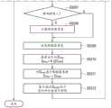
图5是描绘根据示例1A的控制单元在准备阶段的处理的示例的流程图。FIG. 5 is a flowchart depicting an example of processing by the control unit in the preparation phase according to Example 1A.
图6是描绘其中在准备阶段和使用阶段之间负载的温度不均匀的状态的示例的图。FIG. 6 is a diagram depicting an example of a state in which the temperature of the load is not uniform between the preparation stage and the use stage.
图7是描绘在第一子阶段中控制占空比的示例的图。FIG. 7 is a diagram depicting an example of controlling the duty cycle in the first subphase.
图8是描绘根据示例1B的控制单元在准备阶段的处理的示例的流程图。8 is a flowchart depicting an example of processing by the control unit in the preparation phase according to Example 1B.
图9描绘了从电源流向负载的电流与由电源施加到负载的电压之间的关系的示例。9 depicts an example of the relationship between the current flowing from the power supply to the load and the voltage applied by the power supply to the load.
图10是描绘在准备阶段的第一子阶段中的完全充电电压、放电结束电压、对应于完全充电电压的电流和对应于放电结束电压的电流的关系的示例的图。10 is a graph depicting an example of the relationship of the full charge voltage, the discharge end voltage, the current corresponding to the full charge voltage, and the current corresponding to the discharge end voltage in the first subphase of the preparation phase.
图11是描绘在占空比恒定的情况下,当电源的电压在第一子阶段开始时为完全充电电压时负载在准备阶段中的温度变化与当电源的电压在第一子阶段开始时接近于放电结束电压时负载在准备阶段中的温度变化之间的比较的示例的图。Figure 11 is a graph depicting the temperature change of the load during the preparatory phase when the voltage of the power supply is at the fully charged voltage at the beginning of the first sub-phase with a constant duty cycle as close to when the voltage of the power supply is at the beginning of the first sub-phase A graph of an example of a comparison between the temperature changes of the load in the preparation phase at the discharge end voltage.
图12是示例了由PWM控制实现的完全充电电压和放电结束电压之间的关系以及对应于完全充电电压的电流和对应于放电结束电压的电流之间的关系的图。FIG. 12 is a diagram illustrating the relationship between the full charge voltage and the discharge end voltage and the relationship between the current corresponding to the full charge voltage and the current corresponding to the discharge end voltage by PWM control.
图13是描绘根据示例1C的控制单元在准备阶段的处理的示例的流程图。FIG. 13 is a flowchart depicting an example of processing by the control unit in the preparation phase according to Example 1C.
图14是描绘根据示例1D的由控制单元执行的控制的示例的图。FIG. 14 is a diagram depicting an example of control performed by a control unit according to Example ID.
图15是描绘根据示例1D的由控制单元执行的控制的示例的控制框图。15 is a control block diagram depicting an example of the control performed by the control unit according to Example ID.
图16是描绘根据示例1D的控制单元在准备阶段的处理的示例的流程图。16 is a flowchart depicting an example of processing by the control unit in the preparation phase according to Example ID.
图17是描绘根据示例1E的控制单元在准备阶段的处理的示例的流程图。FIG. 17 is a flowchart depicting an example of processing by the control unit in the preparation phase according to Example 1E.
图18是描绘根据示例2A由控制单元执行的控制的示例的控制框图。18 is a control block diagram depicting an example of the control performed by the control unit according to Example 2A.
图19是描绘根据示例2A的控制单元在使用阶段的处理的示例的流程图。FIG. 19 is a flowchart depicting an example of processing of the control unit according to Example 2A in the use phase.
图20是描绘根据示例2B在限制器改变单元中改变限制器宽度的示例的控制框图。20 is a control block diagram depicting an example of changing the limiter width in the limiter changing unit according to Example 2B.
图21是描绘根据示例2B的控制单元8在使用阶段的处理的示例的流程图。FIG. 21 is a flowchart depicting an example of the processing of the control unit 8 in the use phase according to Example 2B.
图22是描绘在限制器单元中使用的限制器宽度的变化和负载的温度升高的状态的示例的图。FIG. 22 is a diagram depicting an example of a state in which the change in the limiter width and the temperature of the load are increased used in the limiter unit.
图23是描绘根据示例2C的限制器宽度的变化的示例的图。23 is a diagram depicting an example of a change in limiter width according to Example 2C.
图24是描绘根据示例2D由控制单元执行的控制的示例的控制框图。24 is a control block diagram depicting an example of the control performed by the control unit according to Example 2D.
图25是描绘根据示例2D的控制单元在使用阶段的处理的示例的流程图。25 is a flowchart depicting an example of processing of the control unit in the use phase according to Example 2D.
图26是描绘根据示例2E的控制单元的使用阶段的示例的流程图。26 is a flowchart depicting an example of a use phase of a control unit according to Example 2E.
图27是描绘根据第二实施例的使用阶段结束温度和根据现有技术的气雾剂产生设备的目标温度之间的比较的示例的图。27 is a diagram depicting an example of a comparison between the end-of-use temperature according to the second embodiment and the target temperature of the aerosol generating apparatus according to the related art.
图28是描绘根据第二实施例的使用阶段结束温度和测量温度值之间的差和根据现有技术的气雾剂产生设备的目标温度和测量温度值之间的差的比较的示例的图。28 is a diagram depicting an example of a comparison of the difference between the end-of-use temperature and the measured temperature value according to the second embodiment and the difference between the target temperature and the measured temperature value of the aerosol generating apparatus according to the related art .
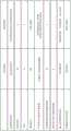
图29是示出根据第三实施例的由控制单元执行的准备阶段和使用阶段的比较的表。FIG. 29 is a table showing a comparison of the preparation phase and the use phase performed by the control unit according to the third embodiment.
图30是描绘根据示例4A的由控制单元执行的控制的示例的控制框图。30 is a control block diagram depicting an example of the control performed by the control unit according to Example 4A.
图31是描绘根据示例4A的控制单元在使用阶段的处理的示例的流程图。FIG. 31 is a flowchart depicting an example of processing of the control unit according to Example 4A in the use phase.
图32是描绘负载3产生温度过冲(overshoot)状态的示例的图。FIG. 32 is a diagram depicting an example in which the
图33是描绘根据示例4B的由控制单元执行的控制的示例的控制框图。33 is a control block diagram depicting an example of the control performed by the control unit according to Example 4B.
图34是描绘根据示例4B的控制单元在使用阶段的处理的示例的流程图。34 is a flowchart depicting an example of processing by the control unit in the use phase according to Example 4B.
图35是描绘根据示例4C的由控制单元执行的控制的示例的控制框图。35 is a control block diagram depicting an example of the control performed by the control unit according to Example 4C.
图36是描绘根据示例4C的控制单元在使用阶段的处理的示例的流程图。36 is a flowchart depicting an example of processing by the control unit in the use phase according to Example 4C.
图37是描绘根据示例4D的由控制单元执行的控制的示例的控制框图。37 is a control block diagram depicting an example of the control performed by the control unit according to Example 4D.
图38是描绘根据示例4D在过冲检测单元中的处理的示例的流程图。38 is a flowchart depicting an example of processing in an overshoot detection unit according to Example 4D.
图39是描绘根据示例4E的由控制单元执行的控制的示例的控制框图。39 is a control block diagram depicting an example of the control performed by the control unit according to Example 4E.
图40是描绘根据示例4E的控制单元在准备阶段的处理的示例的流程图。40 is a flowchart depicting an example of processing by the control unit in the preparation phase according to Example 4E.
图41是描绘根据示例4E的控制单元在使用阶段的处理的示例的流程图。41 is a flowchart depicting an example of processing by the control unit in the use phase according to Example 4E.
图42是描绘根据示例5A的由控制单元执行的控制的示例的控制框图。42 is a control block diagram depicting an example of the control performed by the control unit according to Example 5A.
图43是描绘根据示例5A的控制单元在使用阶段的处理的示例的流程图。43 is a flowchart depicting an example of processing by the control unit in the use phase according to Example 5A.
图44是描绘负载3的温度和限制器宽度的变化的示例的图。FIG. 44 is a graph depicting an example of changes in the temperature of the
图45描绘了根据示例5B的限制器改变单元的示例。45 depicts an example of a limiter changing unit according to Example 5B.
图46是描绘根据示例5B的控制单元在使用阶段的处理的示例的流程图。46 is a flowchart depicting an example of processing by the control unit in the use phase according to Example 5B.
图47是描绘根据示例5C的由控制单元执行的控制的示例的控制框图。47 is a control block diagram depicting an example of the control performed by the control unit according to Example 5C.
图48是描绘根据示例5C的控制单元在使用阶段的处理的示例的流程图。48 is a flowchart depicting an example of processing by the control unit in the use phase according to Example 5C.
图49是描绘根据示例5D的由控制单元执行的控制的示例的控制框图。49 is a control block diagram depicting an example of the control performed by the control unit according to Example 5D.
图50是描绘根据示例5D的控制单元在使用阶段的处理的示例的流程图。50 is a flowchart depicting an example of processing by the control unit in the use phase according to Example 5D.
图51是描绘根据示例5E的负载的温度和限制器宽度的变化的示例的图。51 is a graph depicting an example of changes in temperature of the load and limiter width according to Example 5E.
图52是描绘根据示例5E的控制单元在使用阶段的处理的示例的流程图。52 is a flowchart depicting an example of processing by the control unit in the use phase according to Example 5E.
具体实施方式Detailed ways
下面,将参考附图来描述本实施例。在下面的描述中,省略或基本相同的功能和构成要素用相同的参考符号表示,并且仅在必要时描述。Hereinafter, the present embodiment will be described with reference to the accompanying drawings. In the following description, functions and constituent elements that are omitted or substantially the same are denoted by the same reference numerals, and are described only when necessary.
本实施例的气雾剂产生设备以用于气雾剂产生物(固体加热)的气雾剂产生设备为例进行说明。然而,例如,本实施例的气雾剂产生设备也可以是另一类型或用途的气雾剂产生设备,诸如医用雾化器(喷雾设备)。The aerosol generating apparatus of the present embodiment will be described by taking an aerosol generating apparatus for an aerosol generator (solid heating) as an example. However, for example, the aerosol-generating device of the present embodiment may also be an aerosol-generating device of another type or use, such as a medical nebulizer (spraying device).
以使用通过使用插入到气雾剂产生物中的电加热元件从其内部加热气雾剂产生物的第一加热方法来产生气雾剂的情况为例,描述本实施例的气雾剂产生设备。然而,本实施例的气雾剂产生设备还可以使用另一种加热方法,诸如通过使用设置在气雾剂产生物的外周部分上的环形电加热元件从其外部加热气雾剂产生物的第二加热方法或通过使用感应加热现象从其内部加热气雾剂产生物的第三加热方法。The aerosol generating apparatus of the present embodiment will be described using the first heating method of heating the aerosol generator from the inside thereof by using an electric heating element inserted into the aerosol generator as an example, and the aerosol generating apparatus of the present embodiment will be described as an example. . However, the aerosol generating apparatus of the present embodiment may also use another heating method, such as a first heating element that heats the aerosol generating product from the outside thereof using a ring-shaped electric heating element provided on the outer peripheral portion of the aerosol generating product. A second heating method or a third heating method that heats the aerosol generator from its interior by using an induction heating phenomenon.
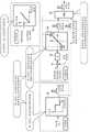
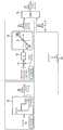
图1是描绘根据实施例的气雾剂产生设备1的基本配置的示例的框图。FIG. 1 is a block diagram depicting an example of a basic configuration of an aerosol generating apparatus 1 according to an embodiment.
气雾剂产生设备1包括安装单元2、负载3、电源4、定时器5、温度测量单元6、电源测量单元7和控制单元8。The aerosol generating device 1 includes a mounting
安装单元2被配置为可拆卸地支撑气雾剂产生物9。The mounting
例如,气雾剂产生物9包括被配置为容纳或承载气雾剂源和风味源中的至少一个的气雾剂形成基板9a。例如,气雾剂产生物9可以是吸烟物品,并且可以形成例如易于使用的诸如棒状形状的形状。For example, the
例如,气雾剂源可以是包括诸如甘油或丙二醇的多元醇的液体或固体。此外,例如,除多元醇之外,气雾剂源还可以包含尼古丁成分。For example, the aerosol source may be a liquid or solid comprising a polyol such as glycerol or propylene glycol. Furthermore, for example, in addition to polyols, the aerosol source may also contain a nicotine component.
例如,气雾剂形成基板9a是其中添加或承载气雾剂源的固体材料,并且可以是例如香烟片。For example, the aerosol-forming
例如,气雾剂形成基板9a可以是能够发出能够产生气雾剂的挥发性化合物使得该基板起到气雾剂源或风味源的作用的基板。挥发性化合物通过加热气雾剂形成基板9a而发出。在本实施例中,气雾剂形成基板9a是气雾剂产生物9的一部分。For example, the aerosol-forming
例如,负载3是电加热元件,并且被配置为在从电源4供电时产生热量,从而加热安装在安装单元2上的气雾剂产生物9。For example, the
电源4是电池或其中组合了电池、场发射晶体管(FET)、用于放电的FET、保护IC(集成电路)、监控设备等的电池组,并且被配置为向负载3供电。电源4是可充电的二次电池,例如可以是锂离子二次电池。电源4可以包括在气雾剂产生设备1中,或者可以与气雾剂产生设备1分开配置。The
定时器5被配置为向控制单元8输出定时器值t,该定时器值t指示在非操作状态下向负载3供电以来的时间。The
在此,非操作状态可以是其中电源4关闭的状态或者其中电源4打开但不等待向负载3供电的状态。非操作状态也可以是待机状态。Here, the non-operating state may be a state in which the
同时,定时器值还可以指示从气雾剂产生开始计算的时间、从负载3开始加热的时间或者从由气雾剂产生设备1的控制单元8开始控制的时间。At the same time, the timer value may also indicate the time counted from the start of aerosol generation, the time from the start of heating of the
例如,温度测量单元6被配置为测量负载3的温度(加热器温度),并将测量温度值输出到控制单元8。同时,具有正温度系数(PTC)特性(电阻值根据温度变化)的加热器可以用于负载3。在这种情况下,温度测量单元6可以被配置为测量负载3的电阻值,并从所测量的电阻值导出负载3的温度(加热器温度)。For example, the temperature measurement unit 6 is configured to measure the temperature (heater temperature) of the
电源测量单元7被配置为测量指示电源4的状态的电源状态值,诸如与电源4的剩余量相关的值、由电源4输出的电压值或从电源4放电的电流或电源4中充电的电流,并将电源状态值输出到控制单元8。The power supply measurement unit 7 is configured to measure a power supply state value indicative of the state of the
在此,例如,作为与电源4的剩余量相关的值,可以使用电源4的输出电压。替代地,可以使用电源4的充电状态(SOC)。可以通过使用开路电压(SOC-OCV)方法或对电源4的充电和放电电流进行积分的电流积分法(库仑计数法)从传感器测量的电压或电流来估计SOC。Here, for example, the output voltage of the
例如,控制单元8被配置为基于从定时器5输入的定时器值和从温度测量单元6输入的测量温度值来控制从电源4供应给负载3的功率。另外,例如,控制单元8可以被配置为通过使用从电源测量单元7输入的电源状态值来执行控制。例如,控制单元8包括计算机、控制器或处理器和存储器,并且计算机、控制器或处理器可以被配置为执行存储器中存储的程序以执行控制。For example, the control unit 8 is configured to control the power supplied from the
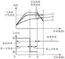
图2是描绘通过根据本实施例的控制供应给负载3的功率和负载3的温度的变化的示例的图。在图2中,横轴表示定时器值t,即时间,纵轴表示供应给负载3的功率和负载3的温度。FIG. 2 is a diagram depicting an example of changes in the power supplied to the
控制单元8被配置为主要在准备阶段和使用阶段之间转换控制。The control unit 8 is configured to switch control mainly between the preparation phase and the use phase.
例如,在准备阶段,其中负载3不能从气雾剂产生物9产生预定量或更多的气雾剂的状态被称为准备状态。例如,准备状态也可以是响应于接收到用户的输入而开始加热负载3之后到允许用户使用气雾剂产生设备1吸入(抽)气雾剂的状态。换句话说,在准备状态下,假设不允许用户使用气雾剂产生设备1吸入气雾剂。For example, in the preparation phase, the state in which the
例如,预定量对应于允许用户吸入气雾剂的气雾剂产生量。For example, the predetermined amount corresponds to an amount of aerosol generation that allows a user to inhale the aerosol.
更具体地,预定量可以是例如可以将有效量的气雾剂输送到用户口中的量。如本文所使用的,有效量可以是可以给予用户源于气雾剂产生物中包括的气雾剂源或风味源的风味和味道的量。预定量还可以是例如由负载3产生并且可以被输送到用户口中的气雾剂量。预定量还可以是例如当负载3的温度等于或高于气雾剂源的沸点时产生的气雾剂量。预定量还可以是例如当供应给负载3的功率等于或高于应当供应给负载3的功率以便从气雾剂产生物9产生气雾剂时从气雾剂产生物9产生的气雾剂量。在准备状态下,负载3可以不从气雾剂产生物9产生气雾剂,即,预定量可以为零。More specifically, the predetermined amount can be, for example, an amount that can deliver an effective amount of the aerosol into the user's mouth. As used herein, an effective amount can be an amount that can impart to a user flavor and taste derived from the aerosol source or flavor source included in the aerosol generator. The predetermined amount may also be, for example, an aerosol dose that is produced by the
当在非操作状态下开始向负载3供电或当负载3处于准备状态时,控制单元8可以通过前馈控制(F/F控制)来控制从电源4供应给负载3的功率。The control unit 8 can control the power supplied from the
当负载3从准备状态转换到使用状态时,控制单元8可以执行反馈控制(F/B控制)或执行反馈控制和前馈控制两者。When the
例如,在使用阶段,其中负载3可以从气雾剂产生物9产生预定量或更多的气雾剂的状态被称为使用状态。例如,使用状态还可以是允许用户吸入气雾剂到气雾剂产生结束的状态。For example, in the use phase, the state in which the
将在稍后描述的第一到第五实施例中具体描述由控制单元8执行的控制。The control performed by the control unit 8 will be specifically described in the first to fifth embodiments described later.
虚线L1表示其中向负载3供电的电源根据定时器值t变化的状态。例如,控制单元8可以通过图1中未示出的开关上的脉冲宽度调制(PWM)控制或脉冲频率调制(PFM)控制来控制从电源4供应给负载3的功率。替代地,控制单元8可以通过图1中未示出的DC/DC转换器升高或降低电源4的输出电压来控制从电源4供应给负载3的功率。在其中负载3处于准备状态的准备阶段中,从电源4向负载3供应高功率,然后降低从电源4供应给负载3的功率。当负载3从准备阶段转换到负载处于使用状态的使用阶段时,从电源4供应给负载3的功率随定时器值t的增加而逐步增加。然后,当负载3的使用状态的结束条件满足时,例如,当负载3的温度达到使用阶段结束温度或者当定时器值t是指示使用阶段结束的阈值或更大值时,停止向负载3供电。The broken line L1 representsa state in which the power supply to the
实线L2表示其中负载3的温度根据定时器值t变化的状态。在准备阶段,当从电源4向负载3供应高功率时,负载3的温度迅速升高。在准备阶段从电源4供应给负载3的功率降低后,负载3的温度保持或略有升高。当转换到使用阶段时,从电源4供应给负载3的功率随时间逐步增加,并且负载3的温度也逐渐升高。控制单元8基于从温度测量单元6输入的测量温度值执行反馈控制,使得负载3的温度在使用阶段结束时将是使用阶段结束温度。The solid line L2 represents a state in which the temperature of the
使用阶段结束温度是设置以便最终在反馈控制中收敛或达到的负载3的温度。本实施例的反馈控制,控制对负载3的供电,使得在使用阶段结束时使用阶段结束温度与测量温度值之间没有差异。The end-of-use temperature is the temperature of the
图3是描绘由本实施例的气雾剂产生设备1的控制单元8执行的控制的示例的控制框图。FIG. 3 is a control block diagram depicting an example of control performed by the control unit 8 of the aerosol generating apparatus 1 of the present embodiment.
控制单元8包括准备单元10、差分单元11、增益单元12、限制器改变(调节)单元13、限制器单元14和比较单元15。稍后将分别具体描述控制单元8的构成元件。The control unit 8 includes a
由控制单元8执行的控制主要具有第一到第五特征。从电源4供应给负载3的功率由控制单元8控制,使得可以缩短准备阶段的时间并在使用阶段稳定气雾剂产生量。The control performed by the control unit 8 mainly has the first to fifth features. The power supplied from the
控制单元8具有在准备阶段中执行前馈控制的第一特征。The control unit 8 has a first feature of performing feedforward control in the preparation phase.
控制单元8具有在使用阶段的反馈控制中扩展限制器单元14的限制器宽度的第二特征。The control unit 8 has a second feature of expanding the limiter width of the
控制单元8具有在准备阶段和使用阶段之间使用不同的控制模式的第三特征。The control unit 8 has a third feature of using different control modes between the preparation phase and the use phase.
控制单元8具有在从准备阶段转换到使用阶段时抑制负载3的温度降低的第四特征。The control unit 8 has a fourth feature of suppressing the temperature drop of the
控制单元8具有在使用阶段当用户吸入气雾剂时恢复温度下降的第五特征。The control unit 8 has a fifth feature that restores the temperature drop during the use phase when the user inhales the aerosol.
例如,本实施例的气雾剂产生设备1被配置为通过负载3加热气雾剂产生物9,从而从气雾剂产生物9产生气雾剂。控制单元8被配置为控制对负载3的供电,使得在负载3加热期间产生的气雾剂不会发生很大变化。For example, the aerosol generating apparatus 1 of the present embodiment is configured to heat the
为了在一个控制模式或一个控制阶段实现稳定的气雾剂产生,需要随时间改变诸如目标温度的控制参数,使得可能难以进行稳定控制。In order to achieve stable aerosol generation in one control mode or one control phase, control parameters such as target temperature need to be changed over time, making stable control potentially difficult.
相比之下,本实施例的控制单元8划分并使用多个不同的控制模式,具体地,用于加热负载3的前馈控制和反馈控制,从而能够稳定气雾剂产生。In contrast, the control unit 8 of the present embodiment divides and uses a plurality of different control modes, in particular, feedforward control and feedback control for the
在稍后描述的第一到第五实施例中,将具体描述第一特征到第五特征。In the first to fifth embodiments to be described later, the first to fifth features will be specifically described.
在本实施例和第一到第五实施例中,作为示例,前馈控制和反馈控制可以被配置为不同的控制模式。前馈控制可以是其中不基于控制目标的控制量来确定操作目标的操作量的控制。换句话说,前馈控制,例如,可以是其中不使用控制目标的控制量作为反馈分量的控制。作为另一示例,前馈控制还可以是其中仅基于预定算法或变量、或者基于预定算法或变量与在向操作目标输出与操作量相关的控制命令之前获取的任何物理量的组合来确定控制目标的控制量的控制。反馈控制,例如,可以是其中基于控制目标的控制量来确定操作目标的操作量的控制。换句话说,反馈控制,例如,可以是其中将控制目标的控制量用作反馈分量的控制。作为另一示例,反馈控制还可以是其中除了预定算法或变量之外,还基于在执行控制期间获取的任何物理量的组合来确定操作目标的操作量的控制。In the present embodiment and the first to fifth embodiments, as an example, the feedforward control and the feedback control may be configured as different control modes. The feedforward control may be control in which the operation amount of the operation target is not determined based on the control amount of the control target. In other words, the feedforward control, for example, may be a control in which the control amount of the control target is not used as a feedback component. As another example, the feedforward control may also be one in which the control target is determined only based on a predetermined algorithm or variable, or based on a combination of the predetermined algorithm or variable and any physical quantity acquired before outputting a control command related to the operation amount to the operation target control of the amount of control. The feedback control, for example, may be control in which the operation amount of the operation target is determined based on the control amount of the control target. In other words, the feedback control, for example, may be a control in which the control amount of the control target is used as the feedback component. As another example, the feedback control may also be a control in which the operation amount of the operation target is determined based on a combination of any physical quantities acquired during execution of the control in addition to a predetermined algorithm or variable.
在第一到第三实施例中,术语“过热”意指其中控制目标的温度略高于要控制的温度(例如,使用阶段结束温度或目标温度)的状态。也就是说,需要注意,其并不一定意味着控制目标处于过高的温度状态。In the first to third embodiments, the term "overheating" means a state in which the temperature of the control target is slightly higher than the temperature to be controlled (eg, the end-of-use temperature or the target temperature). That is, it should be noted that it does not necessarily mean that the control target is in an excessively high temperature state.
(第一实施例)(first embodiment)
在第一实施例中,描述了准备阶段中的前馈控制。In the first embodiment, the feedforward control in the preparation phase is described.
第一实施例的控制单元8当在非操作状态下开始向负载3供电时,或者当负载3处于其中负载3不能从气雾剂产生物产生预定量或更多的气雾剂的准备状态时,通过前馈控制来控制从电源4供应给负载3的功率。这样,通过前馈控制使处于准备状态的负载3的温度升高,使得可以加速负载3的温度升高直到负载处于使用状态。The control unit 8 of the first embodiment when power is supplied to the
控制单元8被配置为执行前馈控制,以便向负载3供应负载3从非操作状态或准备状态转换到使用状态所需的能量。这样,通过前馈控制将负载3的温度升高到使用状态,使得可以缩短负载3到处于使用状态所需的时间。The control unit 8 is configured to perform feedforward control in order to supply the
在此,具体描述控制单元8执行前馈控制以便缩短负载3到处于使用状态的时间。例如,当控制单元8执行反馈控制以将处于非操作状态或准备状态的负载3转换到使用状态时,控制量影响操作量的确定。因此,负载3到处于使用状态所需的时间可能会延长。具体地,在负载3通过反馈控制从准备阶段的相对早期阶段经历使用状态的方面,当增益(传递函数(transfer function))小时,负载3的升温速率慢,而当增益大时,负载3难以收敛到使用状态。此外,在准备阶段中通过反馈控制随时间逐渐升高负载3的目标温度的方面,当负载3的测量温度值逆向(reverse)目标温度时,可能会发生温度升高停滞。相比之下,当控制单元8在准备阶段执行前馈控制时,如上所述当在准备阶段中使用反馈控制时发生的问题不会发生。因此,可以缩短负载3到处于使用状态的时间。因此,对于由控制单元8执行以便将处于非操作状态或处于准备状态的负载3转换到使用状态的控制,可以说,前馈控制比反馈控制更优选。Here, it is specifically described that the control unit 8 performs the feedforward control in order to shorten the time until the
控制单元8可以被配置为在向负载3供应所需的能量之后,执行前馈控制以抑制从电源4供应给负载3的功率。在这种情况下,为了抑制功率,例如,可以抑制供应给负载3的功率以保持负载3的温度。这样,在向负载3供应必要的能量之后,抑制从电源4供应给负载3的功率,使得可以防止气雾剂产生设备1和气雾剂产生物9过热。同时,如果将气雾剂产生设备1置于过热状态,则可能降低气雾剂产生设备1的电源4、控制单元8、负载3、用于电连接电源4和负载3的电路等的寿命。另外,如果将气雾剂产生物9置于过热状态,则由气雾剂产生物9产生的气雾剂的风味和味道可能受损。The control unit 8 may be configured to perform feedforward control to suppress power supplied from the
控制单元8可以被配置为在向负载3供应所需的能量之后,通过反馈控制来控制从电源4供应给负载3的功率。这样,在向负载3供应所需的能量之后执行反馈控制,使得向负载3供应所需的能量之后可以通过稳定性优异的反馈控制改进控制准确度,从而稳定气雾剂产生。The control unit 8 may be configured to control the power supplied from the
由控制单元8执行的前馈控制被划分为第一子阶段和第二子阶段,并且在第一子阶段和第二子阶段中用于前馈控制的变量的值可以被设置为不同。在这种情况下,变量的不同值可以包括不同的控制变量、不同的常数和不同的阈值。这样,前馈控制被划分为第一子阶段和第二子阶段,并且使用不同的变量的值,使得与使用一个控制阶段的情况相比,可以改进控制准确度。同时,在第一子阶段和第二子阶段中用于前馈控制的函数或算法可以被设置为不同。稍后将参考图4到8详细描述第一子阶段和第二子阶段。The feedforward control performed by the control unit 8 is divided into a first subphase and a second subphase, and the values of the variables used for the feedforward control may be set to be different in the first subphase and the second subphase. In this case, the different values of the variables may include different control variables, different constants, and different thresholds. In this way, the feedforward control is divided into a first sub-stage and a second sub-stage, and different values of variables are used, so that the control accuracy can be improved compared to the case of using one control stage. Meanwhile, the function or algorithm for the feedforward control in the first sub-stage and the second sub-stage may be set to be different. The first sub-phase and the second sub-phase will be described in detail later with reference to FIGS. 4 to 8 .
例如,假设第一子阶段比第二子阶段更早地执行。For example, assume that the first subphase executes earlier than the second subphase.
在第一子阶段中供应给负载3的功率(W)或能量(W·h)可以设置为大于在第二子阶段中供应给负载3的功率(W)或能量(W·h)。从而,由于负载3的升温速率是平缓的或者负载3的温度升高在第二子阶段停止,所以可以在前馈控制结束后稳定负载3的温度。The power (W) or energy (W·h) supplied to the
第一子阶段的时间段可以设置得比第二子阶段的时间段长。这样,负载3的状态(温度)主要改变的第一子阶段的时间被设置为比第二子阶段长,结果使得可以缩短前馈控制的总时间段。换句话说,气雾剂产生设备1能够更快速地从气雾剂产生物9产生具有期望的风味和味道的气雾剂。The time period of the first subphase may be set to be longer than the time period of the second subphase. In this way, the time of the first sub-phase in which the state (temperature) of the
控制单元8可以被配置为执行前馈控制,使得负载3在第二子阶段结束时处于使用状态。从而,可以通过使用前馈控制直到第二子阶段结束来稳定地使负载3的温度达到在使用状态下所需的温度。另外,与其中负载3在第二子阶段结束之前处于使用状态的情况相比,由于由电源4放电的能量减少,因此除了改进电源4的比功率(specific power)消耗之外,还可以抑制电源4的劣化。The control unit 8 may be configured to perform feedforward control so that the
控制单元8可以被配置为在第二子阶段中执行前馈控制,以便供应所需的功率或能量,以使负载3处于其中可以产生气雾剂的使用状态并保持负载3的使用状态。这样,在第二子阶段中将保持使用状态所需的功率或能量供应给负载3,使得可以避免在第二子阶段中供应极低功率或极少能量。因此,可以抑制其中负载3不处于使用状态、气雾剂产生设备1不能在使用阶段从气雾剂产生物9产生具有期望的风味和味道的气雾剂的情况,并且降低了电源4的比功率消耗。The control unit 8 may be configured to perform a feedforward control in the second sub-phase in order to supply the required power or energy to bring the
控制单元8可以被配置为在第一子阶段改变为第二子阶段之前执行前馈控制,使得负载3处于使用状态。因此,可以在第一子阶段的早期阶段将负载3置于使用状态,并且通过在第二子阶段中调节负载3的温度来保持使用状态,这增加了控制稳定性。The control unit 8 may be configured to perform feed-forward control before the first sub-phase is changed to the second sub-phase, so that the
控制单元8可以被配置为在第二子阶段执行前馈控制,以便向处于使用状态的负载3供应保持使用状态所需的功率或能量。从而,可以抑制在第二子阶段中供应极低功率或极少能量并且负载3因此不处于使用状态的情况。因此,可以将负载3稳定在使用状态。此外,可以抑制第二子阶段结束时负载3的温度变化。The control unit 8 may be configured to perform feedforward control in the second sub-phase in order to supply the
例如,第二子阶段可以被设置为比第一子阶段更短,并且等于或长于由控制单元8实现(可以实现)的控制的单位时间。从而,执行第二子阶段适当的时间段,使得可以稳定负载3的温度。For example, the second sub-phase may be set to be shorter than the first sub-phase and equal to or longer than the unit time of the control (which can be achieved) by the control unit 8 . Thus, the second sub-phase is performed for an appropriate period of time so that the temperature of the
控制单元8可以被配置为基于初始状态来改变在前馈控制中使用的变量的值,初始状态为在执行负载3的前馈控制期间或之前的状态。在这种情况下,初始状态,例如,包括初始温度等。变量的值的改变包括控制变量的改变、常数的改变和阈值的改变。这样,基于初始状态改变反馈控制中使用的变量的值,使得可以在前馈控制的执行期间和/或结束时抑制可能是由于诸如产品误差、初始条件、大气温度等外部因素引起的负载3的温度变化。The control unit 8 may be configured to change the value of the variable used in the feedforward control based on an initial state, which is a state during or before the execution of the feedforward control of the
控制单元8可以被配置为改变变量的值,以便向负载3供应用于处于初始状态的负载3转换到使用状态所需的功率或能量。从而,可以在反馈控制结束时抑制可能是由于诸如产品误差、初始条件、大气温度等外部因素引起的使用状态下的负载3的温度变化。The control unit 8 may be configured to change the value of the variable in order to supply the
控制单元8可以被配置为获取与电源4的剩余量相关的值,并且在前馈控制执行期间或之前基于与剩余量相关的值来改变在前馈控制中使用的变量的值。从而,可以抑制可能是由于电源4的剩余量的差异引起的负载3的温度变化。The control unit 8 may be configured to acquire a value related to the remaining amount of the
控制单元8可以被配置为在与剩余量相关的值较小时增加从电源4供应给负载3的功率的占空比、电压和接通时间中的至少一个。例如,在使用DC/DC转换器的情况下,由于设置在DC/DC转换器的输出侧的平滑电容器的平滑动作,脉冲波可能不会被施加到负载3。因此,控制单元8可以基于与剩余量相关的值来控制向负载3供电的时间(接通时间)。从而,可以抑制由于电源4的剩余量的差异引起的负载3的温度变化。The control unit 8 may be configured to increase at least one of the duty ratio, the voltage and the on-time of the power supplied from the
控制单元8可以被配置为改变变量的值,使得基于与从电源4获取的第一剩余量相关的值从电源4供应给负载3的第一能量,与基于与从电源4获取的第二剩余量相关且不同于与第一剩余量相关的值的值从电源4供应给负载3的第二能量基本相同。从而,例如,可以执行PWM控制,使得向负载3供应恒定功率,而不考虑电源4的剩余量。结果,可以抑制由于电源4的剩余量的差异引起的负载3的温度变化。The control unit 8 may be configured to change the value of the variable such that the first energy supplied from the
控制单元8可以被配置为基于在执行前馈控制期间或之前的负载3的状态以及与剩余量相关的值来获取与电源4的剩余量相关的值,并改变在前馈控制中使用的变量的值。从而,可以在前馈控制执行期间和/或结束时抑制负载3的温度变化,该温度变化除了是由于电源4的剩余量的差异引起之外,还可能是由于诸如产品误差、初始条件、大气温度等外部因素引起的。The control unit 8 may be configured to acquire a value related to the residual amount of the
控制单元8可以被配置为当负载3更接近其中负载可以产生气雾剂的使用状态时,降低从电源4供应给负载3的功率的占空比、电压和接通时间中的至少一个,并且被配置为在与剩余量相关的值较大时基于负载3的状态降低功率的占空比、电压和接通时间中的至少一个。在这种情况下,例如,可以用电源4的剩余量校正从负载3的状态(诸如初始温度)获得的功率的占空比、电压和接通时间中的至少一个,使得可以在前馈控制执行期间和/或结束时抑制负载3的温度变化,该温度变化除了是由于诸如产品误差、初始条件、大气温度等外部因素引起之外,还可能是由于电源4的剩余量引起的。The control unit 8 may be configured to reduce at least one of a duty cycle, a voltage and an on-time of power supplied from the
控制单元8可以被配置为改变占空比、电压和接通时间,使得基于与从电源4获取的第一剩余量相关的值从电源4供应给负载3的第一能量与基于与从电源4获取的第二剩余量相关且不同于与第一剩余量相关的值的值从电源4供应给负载3的第二能量基本相同。在这种情况下,取决于负载3的状态,可以将第一能量和第二能量设置为不同。从而,例如,可以执行PWM控制,使得依据第一剩余量和第二剩余量向负载3供应相同的功率。结果,可以在前馈控制执行期间和/或结束时抑制负载3的温度变化,该温度变化除了是由于诸如产品误差、初始条件、大气温度等外部因素引起之外,还可能是由于电源4的剩余量引起的。The control unit 8 may be configured to vary the duty cycle, the voltage and the on-time so that the first energy supplied from the
控制单元8可以被配置为基于在执行前馈控制期间或之前负载3的电阻值或负载3的劣化状态来改变在前馈控制中使用的变量的值。在这种情况下,控制单元8可以被配置为,例如,基于负载3的使用次数或使用次数的累积值来获得劣化状态。从而,即使当负载3劣化并且因此室温下的电阻值等随气雾剂产生设备1的使用次数的增加而变化时,负载3的温度也可以稳定。此外,即使当使用具有正温度系数特性(PTC特性)的负载3,并且负载3劣化且其特性改变时,负载3的温度也可以稳定。The control unit 8 may be configured to change the value of the variable used in the feedforward control based on the resistance value of the
还可以在控制单元8执行程序时实现控制单元8进行的各种控制。Various controls performed by the control unit 8 can also be realized when the control unit 8 executes a program.
关于第一实施例,在下面的实施例1A到1E中进一步描述具体的控制的示例。Regarding the first embodiment, specific examples of control are further described in the following Embodiments 1A to 1E.
<示例1A><Example 1A>
图4是描绘根据示例1A由控制单元8执行的控制的示例的控制框图。FIG. 4 is a control block diagram depicting an example of the control performed by the control unit 8 according to Example 1A.
在准备阶段,控制单元8的准备单元10获取由定时器5输出的定时器值t,并获得与定时器值t相对应的占空比命令值(duty command value)。控制单元8根据获得的占空比命令值,切换设置在用于电连接负载3和电源4的电路中的开关25,如图9所示,从而基于占空比命令值控制供应给负载3的功率。In the preparation phase, the
在示例1A中,基于占空比命令值(更具体地,由占空比命令值指示的占空比)来切换负载3的加热状态。然而,当控制设置在用于电连接负载3和电源4的电路中的DC/DC转换器而不是开关25时,可以基于,例如,供应给负载3的电流、施加到负载3的电压或其命令值来切换负载3的加热状态,并且用于指示负载3的加热状态的值可以视情况改变。In Example 1A, the heating state of the
准备阶段还包括第一子阶段和第二子阶段。第一子阶段和第二子阶段还可以通过占空比命令值(更具体地,由占空比命令值指示的占空比)来区分。此外,第一子阶段和第二子阶段可以通过供应给负载3的电流、施加到负载3的电压或其命令值来区分。The preparation phase also includes a first subphase and a second subphase. The first subphase and the second subphase may also be distinguished by a duty cycle command value (more specifically, the duty cycle indicated by the duty cycle command value). Furthermore, the first sub-phase and the second sub-phase can be distinguished by the current supplied to the
第一子阶段的时间段Δt1是从向非操作状态的负载3供电开始到时间t1的时间段。The time period Δt1 of the first subphase is the time period from the start of supplying the
第二子阶段的时间段Δt2是从时间t1到准备阶段的结束时间t2的时间段。The time period Δt2 of the second sub-phase is the time period from time t1 to the end time t2 of the preparation phase.
第一子阶段的时间段Δt1比第二子阶段的时间段Δt2长。The time period Δt1 of the first subphase is longer than the time period Δt2 of the second subphase.
第一子阶段的占空比D1大于第二子阶段的占空比D2。在示例1A中,随着占空比的增加,从电源4供应给负载3的功率被设置为更大。因此,在第一子阶段中从电源4供应给负载3的功率大于在第二子阶段中从电源4供应给负载3的功率。The duty cycle D1 of the first sub-phase is greater than the duty cycle D2 of the second sub-phase. In Example 1A, as the duty ratio increases, the power supplied from the
在第一子阶段中,控制单元8基于指示大占空比的占空比命令值控制供应给负载3的功率,直到负载3(气雾剂产生物9)的温度达到气雾剂产生温度。从而,可以在从电源4向负载3供电(馈电)开始的早期阶段从气雾剂产生物9产生气雾剂。In the first subphase, the control unit 8 controls the power supplied to the
在第二子阶段,控制单元8基于指示小于第一子阶段的占空比的占空比的占空比命令来控制供应给负载3的功率,以便抑制负载3的温度变化,直到负载转换到使用阶段为止,并且保持负载3(气雾剂产生物9)的温度至气雾剂产生温度或更高。即使在第一子阶段结束时的温度略有变化,控制单元8也可以通过在第二子阶段中的控制抑制并吸收该变化。从而,在使用阶段中从气雾剂产生物9产生的气雾剂的风味和味道变得稳定。In the second subphase, the control unit 8 controls the power supplied to the
这样,在准备阶段,通过第一子阶段向负载3供应高功率以快速提高负载3的温度,并且通过第二子阶段向负载3供应用于保温的低功率,使得可以在准备阶段之后的使用阶段稳定气雾剂产生量及其风味和味道。In this way, during the preparation phase, the
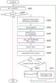
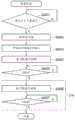
图5是描绘根据示例1A的控制单元8在准备阶段的处理的示例的流程图。FIG. 5 is a flowchart depicting an example of processing by the control unit 8 in the preparation stage according to Example 1A.
在步骤S501中,准备单元10确定是否存在产生气雾剂的请求。当确定不存在产生气雾剂的请求(步骤S501中的“否”)时,准备单元10重复步骤S501。作为第一示例,准备单元10可以在步骤S501中基于是否从用户发出用于开始加热负载3的输入来确定是否存在产生气雾剂的请求。更具体地,当从用户发出用于开始加热负载3的输入时,准备单元10可以确定存在气雾剂产生的请求。另一方面,当没有从用户发出用于开始加热负载3的输入时,准备单元10可以确定不存在产生气雾剂的请求。作为第二示例,气雾剂产生设备1具有用于检测用户吸入的传感器(图1中未示出),并且可以使用由传感器检测到的用户吸入作为用于开始加热负载3的输入。作为第三示例,气雾剂产生设备1具有按钮、开关、触摸面板和用户界面中的至少一个(图1中未示出),并且可以使用其上的操作作为用于开始加热负载3的输入。In step S501, the
在步骤S502中,当确定存在产生气雾剂的请求时,准备单元10激活定时器5。In step S502, when it is determined that there is a request to generate an aerosol, the
在步骤S503中,开始将定时器值t从定时器5输入到准备单元10。In step S503, the input of the timer value t from the
在步骤S504中,准备单元10基于在第一子阶段中指示占空比D1的占空比命令来切换在图9所示的设置在用于电连接负载3和电源4的电路中的开关25,从而控制供应给负载3的功率。In step S504, the
在步骤S505中,准备单元10确定定时器值t是第一子阶段的结束时间t1还是更长。当确定定时器值t不是第一子阶段的结束时间t1或更长(步骤S505中的确定结果为“否”)时,准备单元10重复步骤S505。In step S505, the
在步骤S506中,当确定定时器值t是第一子阶段的结束时间t1或更长(步骤S505中的确定结果为“是”)时,准备单元10基于指示第二子阶段的占空比D2的占空比命令值来控制供应给负载3的功率。In step S506, when it is determined that the timer value t is the end time t1 of thefirst subphase or longer (the determination result in step S505 is YES), the
在步骤S507中,准备单元10确定定时器值t是第二子阶段的结束时间t2还是更长。当确定定时器值t不是第二子阶段的结束时间t2或更长(步骤S507中的确定结果为“否”)时,准备单元10重复步骤S507。当确定定时器值t是第二子阶段的结束时间t2或更长(步骤S507中的确定结果为“是”)时,准备单元10结束准备阶段并转换到使用阶段。In step S507, the
如上所述,在示例1A中,控制单元8通过在准备阶段使用前馈控制来控制负载3的加热。因此,在请求产生气雾剂并且从电源4向负载3供电开始之后,可以增加负载3的升温速率。As described above, in Example 1A, the control unit 8 controls the heating of the
在示例1A中,在准备阶段,前馈控制将负载3的温度升高到可以吸入气雾剂的温度。因此,可以缩短请求产生气雾剂后到用户能够吸入气雾剂的时间。In Example 1A, during the preparation phase, the feedforward control raises the temperature of the
在示例1A中,由于在准备阶段的第一子阶段中供应给负载3的功率增加一次(once),然后在准备阶段的第二子阶段供应给负载3的功率降低,所以可以抑制负载3过热。In Example 1A, since the power supplied to the
控制单元8通过在准备阶段使用前馈控制来控制负载3的加热,使得可以在请求产生气雾剂并且从电源4向负载3供电开始之后增加负载3的升温速率,因而可以缩短请求产生气雾剂后到用户能够吸入气雾剂的时间,并且可以抑制负载3过热。在此,详细描述原因。例如,如果控制单元8在准备阶段中通过使用反馈控制来控制负载3的加热,则控制量影响操作量的决定,使得负载3的升温速率可能变慢。同样,由于类似的原因,在请求产生气雾剂后到用户能够吸入气雾剂的时间可能会延长。具体地,在负载3被加热到可以从准备阶段的相对早期阶段产生气雾剂的温度的方面,当增益小时,负载3的升温速率慢,而当增益大时,负载3的温度难以收敛到可以产生气雾剂的温度,因此负载3可能过热。此外,在负载3的目标温度随时间逐渐升高的方面,当负载3的测量温度值逆向目标温度时,温度升高可能发生停滞。然而,当控制单元8在准备阶段通过使用前馈控制来控制负载3的加热时,不会出现问题。因此,在请求产生气雾剂并且从电源4向负载3供电开始之后,可以增加负载3的升温速率。此外,可以缩短请求产生气雾剂后到用户可以吸入气雾剂的时间。除此之外,还可以抑制负载3过热,并缩短直到负载3处于使用状态的时间。因此,对于在准备阶段用于加热负载3的控制而言,可以说前馈控制比反馈控制更优选。The control unit 8 controls the heating of the
<示例1B><Example 1B>
在示例1B中,描述了基于指示负载3的温度的测量温度值在第一子阶段中控制供应给负载3的功率的变化。In Example IB, controlling the variation of the power supplied to the
图6是描绘其中在准备阶段和使用阶段之间负载的温度不均匀的状态的示例的图。图6是描绘定时器值t与负载3的温度之间的关系以及定时器值t与从电源4供应给负载3的功率之间的关系的示例的图。横轴表示定时器值t。纵轴表示负载3的温度或供应给负载3的功率的占空比。FIG. 6 is a diagram depicting an example of a state in which the temperature of the load is not uniform between the preparation stage and the use stage. FIG. 6 is a diagram depicting an example of the relationship between the timer value t and the temperature of the
即使准备阶段结束,当负载从准备阶段转换到使用阶段或在刚转换到使用阶段之后,负载3的温度可能从准备阶段结束温度快速变化。Even if the preparation phase ends, when the load is switched from the preparation phase to the use phase or just after the transition to the use phase, the temperature of the
当准备阶段结束温度不稳定于或接近气雾剂产生温度时,负载3的温度呈现急剧变化,使得负载3的温度至少在使用阶段的早期阶段可能不会达到气雾剂产生温度。When the temperature at the end of the preparation phase is not stable at or close to the aerosol generation temperature, the temperature of the
例如,当准备阶段结束时,作为导致负载3温度变化的因素,可以假设以下三个因素。For example, when the preparation phase ends, as factors causing the temperature change of the
第一因素是负载3的初始状态的变化(shift),例如,负载3的温度在负载3的温度开始升高时的变化。The first factor is a shift in the initial state of the
第二因素是电源4的输出电压的变化,这可能是由于剩余量的减少或电源4的劣化引起的。The second factor is a change in the output voltage of the
第三因素是气雾剂产生物9或气雾剂产生设备1的产品误差。The third factor is the product error of the
通过在第一子阶段中执行以下控制,可以至少放宽第一和第二因素。At least the first and second factors can be relaxed by performing the following controls in the first subphase.
通过第二子阶段中的保温控制可以至少放宽第三因素。At least the third factor can be relaxed by holding the control in the second sub-stage.
图7是描绘在第一子阶段中对占空比D1进行控制的示例的图。图7描绘了定时器值t与负载3的温度之间的关系,以及定时器值t与占空比之间的关系。横轴表示定时器值t。纵轴表示负载3的温度或供应给负载3的功率的占空比。FIG. 7 is a diagram depicting an example of controlling the duty cycle D1 in the first sub-phase. FIG. 7 depicts the relationship between the timer value t and the temperature of the
如果第一子阶段的占空比D1被设置为常数,并且第二子阶段的占空比D2被设置为常数,则当负载3在第一子阶段开始时的温度低或高时,在第二子阶段结束时,负载3的温度也低或高,并且负载3的温度在准备阶段结束时变化。If the duty cycle D1 of thefirst subphase is set to be constant, and the duty cycle D2 of thesecond subphase is set to be constant, then when the temperature of
与此相对,根据示例1B的控制单元8基于第一子阶段开始时的测量温度值改变第一子阶段的占空比D1,从而基于第一子阶段开始时负载3的温度的变化抑制负载3的温度在准备阶段结束时变化。In contrast to this, the control unit 8 according to Example 1B changes the duty cycle D1 of the first sub-phase based on the measured temperature value at the start of the first sub-phase, thereby suppressing the load based on the change in the temperature of the
更具体地,当第一子阶段开始时的测量温度值小时,控制单元8增加第一子阶段的占空比D1。与此相对,当第一子阶段开始时的测量温度值大时,控制单元8减小第一子阶段的占空比D1。More specifically, when the measured temperature value at the start of the first sub-phase is small, the control unit 8 increases the duty cycle D1 of the first sub-phase. In contrast to this, when the measured temperature value at the start of the first sub-phase is large, the control unit 8 reduces the duty cycle D1 of the first sub-phase.
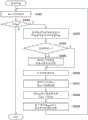
图8是描绘根据示例1B的控制单元8在准备阶段的处理的示例的流程图。FIG. 8 is a flowchart depicting an example of processing by the control unit 8 in the preparation stage according to Example 1B.
从步骤S801到步骤S803的处理与图5中从步骤S501到步骤S503的处理相同。The processing from step S801 to step S803 is the same as the processing from step S501 to step S503 in FIG. 5 .
在步骤S804中,将第一子阶段开始时的测量温度值Tstart作为初始状态从温度测量单元6输入到准备单元10。In step S804, the measured temperature value Tstart at the start of the first sub-phase is input from the temperature measurement unit 6 to the
在步骤S805中,准备单元10基于测量温度值Tstart获得第一子阶段的占空比D1(Tstart),并基于指示第一子阶段的占空比D1(Tstart)的占空比命令值,切换设置在用于电连接负载3和电源4的电路中的开关25(如图9所示),从而控制供应给负载3的功率。In step S805, the
从步骤S806到步骤S808的处理与图5中从步骤S505到步骤S507的处理相同。The processing from step S806 to step S808 is the same as the processing from step S505 to step S507 in FIG. 5 .
在如上所述的示例1B中,基于第一子阶段开始时负载3的温度的变化,可以抑制负载3的温度在准备阶段结束时变化,使得可以在准备阶段之后的使用阶段中稳定气雾剂的产生量及其风味和味道。In Example 1B as described above, based on the change in the temperature of the
在示例1B中,控制单元8基于在第一子阶段开始时的测量温度值Tstart改变第一子阶段的占空比命令值。然而,控制单元8可以基于测量温度值Tstart来改变第二子阶段的占空比命令值,或者可以基于测量温度值Tstart改变第一子阶段的占空比命令值和第二子阶段的占空比命令值两者。In Example 1B, the control unit 8 changes the duty cycle command value of the first sub-phase based on the measured temperature value Tstart at the start of the first sub-phase. However, the control unit 8 may change the duty command value of the second subphase based on the measured temperature valueTstart , or may change the duty command value of the first subphase and the second subphase based on the measured temperature valueTstart Duty cycle command value for both.
<示例1C><Example 1C>
在示例1C中,描述了基于作为与电源4的剩余量相关的值的示例的电源4的SOC改变第一子阶段中的功率的控制,或者即使当电源4的SOC改变时也使施加到负载3的电压恒定的PWM控制。In Example 1C, the control of changing the power in the first sub-phase based on the SOC of the
图9描绘了从电源4流向负载3的电流与由电源4施加到负载3的电压之间的关系的示例。电流表23输出从电源4流向负载3的电流A,电压表24输出从电源4施加到负载3的电压V。另外,控制单元8(图9中未示出)获取从电流表23输出的值和从电压表24输出的值。同时,作为电流表23和电压表24,可以使用每个都具有嵌入其中的已知电阻值的分流电阻器的电流表和电压表,或者可以使用霍尔元件。同时,从重量或体积的观点来看,使用其中嵌入分流电阻器的元件是有利的,并且从测量准确度或对测量目标影响较小的观点来看,使用霍尔元件是有利的。此外,电流表23或电压表24也可以将测量值输出为数字值或模拟值。当电流表23或电压表24输出模拟值时,控制单元8可通过A/D转换器将模拟值转换为数字值。FIG. 9 depicts an example of the relationship between the current flowing from the
此外,电源4和负载3通过电路电连接,使得当控制单元8打开/关闭(切换)设置在电路中的开关25时,控制从电源4到负载3的供电。作为示例,开关25可以包括开关、接触器和晶体管中的至少一个。同时,电路还可以具有DC/DC转换器,而不是开关25或除了开关25之外。在这种情况下,控制单元8控制DC/DC转换器,从而控制从电源4到负载3的供电。Further, the
在图9中,电压表24设置地比开关25更靠近负载3。然而,为了使用SOC-OCV方法以获取电源4的SOC,可以设置比开关25更靠近电源4的其他电压表。其他电压表能够输出电源4的开路电压(OCV)。In FIG. 9 , the
图10是描绘在准备阶段的第一子阶段中对应于电源4的剩余量的输出电压和输出电流之间的关系的示例的图。在图10中,横轴表示定时器值t,并且应当注意,省略了时间t1之后的第二子阶段。纵轴表示从电源4输出的电压或电流。另外,在图10中,虚线表示当电源4的剩余量为100%时的电压和电流。实线表示当由于电源4的剩余量处于或接近0%而输出放电结束电压或接近放电结束电压的电压时的电压和电流。在图10中,Vfull-charged和VE.O.D分别表示电源4的完全充电电压和放电结束电压。FIG. 10 is a diagram depicting an example of the relationship between the output voltage and the output current corresponding to the remaining amount of the
在图10中,假设第一子阶段的占空比D1为100%。In FIG. 10, it is assumed that the duty cycle D1 of thefirst sub-phase is 100%.
为简化起见,当假设用于电连接负载3和电源4的电路的电阻为可忽略的小并且该电路不是与负载3同时被电源4供电的目标时,通过将电源4的输出电压除以负载3的电阻值R获得对应于电源4的剩余量的输出电流。For simplicity, when it is assumed that the resistance of the circuit used to electrically connect
当使用上述简化模型时,通过完全充电电压/负载3的电阻(Vfull-charged/R)获得当电源4的输出电压为完全充电电压时输出的完全充电电流Ifull-charged。When using the above simplified model, the fully charged current Ifull-charged output when the output voltage of the
当使用上述简化模型时,通过放电结束电压/负载3的电阻(VE.O.D/R)获得当电源4的输出电压为放电结束电压时输出的电流IE.O.D/R。When the above simplified model is used, the output current IEOD /R when the output voltage of the
在准备阶段的第一子阶段,当电源4的输出电压为完全充电电压Vfull-charged时输出的电流Vfull-charged/R大于当电源4的输出电压为放电结束电压VE.O.D时输出的电流VE.O.D/R。In the first sub-stage of the preparation stage, when the output voltage of the
图11是描绘在占空比恒定的情况下,当电源4的电压在第一子阶段开始时是完全充电电压时负载3在准备阶段中的温度变化,与当电源4的电压在第一子阶段开始时接近放电结束电压时负载4在准备阶段中的温度变化之间的比较的示例的图。在图11中横轴表示定时器值t。纵轴表示温度或供应给负载3的功率的占空比。如上所述,与电源4处于完全充电电压的情况相比,当电源4接近放电结束电压时从电源4供应给负载3的电流和施加的电压更小。因此,当电源4处于完全充电电压时负载3在准备阶段的温度变化大于当电源4接近放电结束电压时负载3在准备阶段的温度变化。FIG. 11 is a graph depicting the temperature change of
同时,当电源4处于完全充电电压时,在第一子阶段从电源4供应给负载3的功率由以下等式表示。Meanwhile, when the
W=(Vfull-charged·D)2/RW=(Vfull-charged ·D)2 /R
另一方面,当电源4接近放电结束电压时,在第一子阶段从电源4供应给负载3的功率由以下等式表示。On the other hand, when the
W=(VE.O.D·D)2/RW=(VEOD ·D)2 /R
在这两个等式中,D表示供应给负载3的功率的占空比。In both equations, D represents the duty cycle of the power supplied to the
获得两个等式之间的差。当电源4处于完全充电电压时在第一子阶段中从电源4供应给负载3的功率与当电源4接近放电结束电压时在第一子阶段中从电源4供应给负载3的功率之间的差用以下等式表示。Get the difference between the two equations. The difference between the power supplied from the
ΔW={(Vfull-charged·D)2-(VE.O.D·D)2}/RΔW={(Vfull-charged ·D)2 -(VEOD ·D)2 }/R
例如,当完全充电电压Vfull-charged为4.2V,放电结束电压VE.O.D为3.2V,负载3的电阻值R为1.0Ω,占空比D为100%时,功率差ΔW为7.4W时。For example, when the fully charged voltage Vfull-charged is 4.2V, the discharge end voltage VEOD is 3.2V, the resistance value R of the
因此,即使当诸如与负载3和气雾剂产生物9之间的热传递相关的条件(例如,接触面积等)、负载3的初始温度、气雾剂产生物9的热容等的各种条件是相同的,准备阶段结束时负载3的温度也根据电源4的剩余量而变化。Therefore, even when various conditions such as conditions related to heat transfer between the
因此,在示例1C中,控制单元8基于电源4的输出电压改变第一子阶段的功率,即占空比,从而抑制负载3的温度在准备阶段结束时变化。Therefore, in Example 1C, the control unit 8 changes the power of the first sub-phase, ie, the duty cycle, based on the output voltage of the
此外,在示例1C中,控制单元8可以执行使施加到负载3的电压恒定的PWM控制,以便排除电源4的输出电压的影响。在PWM控制中,改变脉冲电压波形,使得有效电压波形的面积相同。这里,可以从“施加的电压×占空比”获得有效电压。在另一实例中,可以从均方根(RMS)获得有效电压。Furthermore, in Example 1C, the control unit 8 may perform PWM control to make the voltage applied to the
图12是例示当根据电源4的剩余量执行PWM控制时电源4的输出电压和输出电流之间的关系的图。在图12中,横轴指示定时器值t,并且应当注意,省略了时间t1之后的第二子阶段。纵轴指示从电源4输出的电压或电流。FIG. 12 is a diagram illustrating the relationship between the output voltage and the output current of the
在准备阶段,控制单元8执行控制,使得对应于完全充电电压Vfull-charged的脉冲电压波形的面积与对应于放电结束电压VE.O.D的电压波形的面积相同。In the preparation stage, the control unit 8 performs control such that the area of the pulse voltage waveform corresponding to the fully charged voltageVfull-charged is the same as the area of the voltage waveform corresponding to the discharge end voltageVEOD .
等式(1)表示与完全充电电压Vfull-charged对应的占空比Dfull-charged、完全充电电压Vfull-charged、放电结束电压VE.O.D和与放电结束电压VE.O.D对应的占空比DE.O.D之间的关系。Equation (1) expresses the duty ratio Dfull-charged corresponding to the full charge voltage V full-charged , the full charge voltage Vfull-charged , the discharge end voltageVEOD , and the duty cycle D corresponding to the discharge end voltageVEOD relationship betweenEODs .
[等式1][Equation 1]

在式(1)中,当与放电结束电压VE.O.D对应的占空比DE.O.D被设置为100%时,与完全充电电压Vfull-charged对应的占空比Dfull-charged为76%。In Equation (1), when the duty ratio DEOD corresponding to the discharge end voltage VEOD is set to 100%, the duty ratio D full-charged corresponding to the fully charged voltage V full-charged is 76%.
这样,控制单元8可以通过基于电源4在包括在准备阶段中的第一子阶段的输出电压的占空比来抑制负载3的温度在准备阶段结束时变化。In this way, the control unit 8 can suppress the temperature of the
图13是描绘根据示例1C的控制单元8在准备阶段的处理的示例的流程图。FIG. 13 is a flowchart depicting an example of processing by the control unit 8 in the preparation stage according to Example 1C.
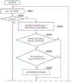
从步骤S1301到步骤S1303的处理与图5中从步骤S501到步骤S503的处理相同。The processing from step S1301 to step S1303 is the same as the processing from step S501 to step S503 in FIG. 5 .
在步骤S1304中,电源测量单元7测量电源4的输出电压(电池电压)VBatt。In step S1304, the power supply measuring unit 7 measures the output voltage (battery voltage) VBatt of the
在步骤S1305中,准备单元10获得占空比D1=(VE.O.D·DE.O.D)/VBatt。In step S1305, the
在步骤S1306中,准备单元10基于指示占空比D1的占空比命令切换设置在用于电连接负载3和电源4的电路中的开关25(如图9所示),从而控制供应给负载3的功率。In step S1306, the
从步骤S1307到步骤S1309的处理与图5中从步骤S505到步骤S507的处理相同。The processing from step S1307 to step S1309 is the same as the processing from step S505 to step S507 in FIG. 5 .
在如上所述的示例1C中,根据作为与电源4的剩余量相关的值的示例的电源4的输出电压来改变包括在准备阶段中的第一子阶段的占空比D1,使得可以抑制负载的温度在准备阶段结束时变化。因此,可以在准备阶段之后的使用阶段中稳定气雾剂产生量和风味和味道。In Example 1C as described above, the duty ratio D1 of the first sub-phase included in the preparation phase is changed according to the output voltage of the
在示例1C中,已经描述了将电源4的输出电压用作与电源4的剩余量相关的值的示例的方面。替代地,可以根据作为与电源4的剩余量相关的值的另一示例的电源4的SOC改变包括在准备阶段中的第一子阶段的占空比D1。In Example 1C, the aspect of the example in which the output voltage of the
众所周知,在SOC用作与电源4的剩余量相关的值的情况下,当电源4的电压为完全充电电压时,SOC被定义为100%。另一方面,当电源4的电压为放电结束电压时,SOC被定义为0%。此外,SOC根据电源4的剩余量从100%持续变化到0%。例如,当使用锂离子二次电池作为电源4时,完全充电电压和放电结束电压分别为4.2V和3.2V。然而,电源4的完全充电电压和放电结束电压不限于此。如上所述,控制单元8可以通过SOC-OCV方法、电流积分法(库仑计数法)等获得电源4的SOC。As is well known, in the case where the SOC is used as a value related to the remaining amount of the
<示例1D><Example 1D>
为了以更高的准确度控制负载3在准备阶段结束时的温度,优选地基于多个初始条件执行控制,例如,与负载3的温度和电源4的剩余量相关的两个值。In order to control the temperature of the
在示例1D中,执行基于测量温度值THTR获得与放电结束电压VE.O.D相对应的占空比DE.O.D(THTR),基于放电结束电压VE.O.D、占空比DE.O.D(THTR)和电池电压VBatt获得第一子阶段的占空比D1,以及通过使用占空比D1来切换设置在图9所示的用于电连接负载3和电源4的电路中的开关25的前馈控制。In Example ID, it is performed to obtain the duty ratio DEOD (THTR ) corresponding to the discharge end voltageVEOD based on the measured temperature value THTR , based on the discharge end voltageVEOD , the duty cycle DEOD (THTR ) and the battery The voltage VBatt obtains the duty cycle D1 of the first sub-phase, and by using the duty cycle D1 to switch the feedforward of the
图14是描绘根据示例1D的由控制单元8执行的控制的示例的图。在图14中,横轴表示定时器值t。纵轴表示温度或供应给负载3的功率的占空比。FIG. 14 is a diagram depicting an example of control performed by the control unit 8 according to Example ID. In FIG. 14, the horizontal axis represents the timer value t. The vertical axis represents the temperature or the duty ratio of the power supplied to the
图14的左图绘示了占空比与负载3的温度变化之间的关系。在图14的左图中,只改变了第一子阶段的占空比D1和第二子阶段的占空比D2。例如,当占空比D1被设置为用粗实线所示的大占空比时,负载3的温度如图14左上图中的实线所示而变化。另一方面,例如,当占空比D1被设置为用细实线所示的小占空比时,负载3的温度如图14左上图中的虚线所示而变化。如图14的左图所示,负载3的温度在第一子阶段根据占空比D1的级别(高度)变化,即,负载3的温度在每个定时器值t处不同。The left graph of FIG. 14 shows the relationship between the duty ratio and the temperature change of the
也就是说,即使诸如与负载3的温度和电源4的剩余量相关的值的初始条件不同,当第一子阶段的占空比D1被调节时,也可以进一步高度地控制负载3在准备阶段结束时的温度。That is, even if the initial conditions such as the values related to the temperature of the
因此,根据示例1D的控制单元8执行控制,使得负载3在第一子阶段开始时的温度越高(初始温度),第一子阶段的占空比D1就越小,并且负载3在第一子阶段开始时的温度越低,则第一子阶段的占空比D1就越大,如图14的右图所示。Therefore, the control unit 8 according to Example 1D performs control such that the higher the temperature of the
同时,除了第一子阶段开始时的负载3的温度外,根据示例1D的控制单元8还可以基于与电源4的剩余量相关的值(例如,电源4的输出电压)来改变占空比D1。这样,如图14的右图所示,即使诸如与负载3的温度和电源4的剩余量相关的值的初始条件不同,也可以进一步高度控制负载3在准备阶段结束时的温度并使其接近特定值。Meanwhile, in addition to the temperature of the
图15是描绘根据示例1D由控制单元8执行的控制的示例的控制框图。FIG. 15 is a control block diagram depicting an example of the control performed by the control unit 8 according to Example ID.
在示例1D中,控制单元8包括初始设置单元16和准备单元10。In Example ID, the control unit 8 includes an
初始设置单元16具有负载3的温度和对应于放电结束电压VE.O.D的占空比DE.O.D之间的关系。The
初始设置单元16从温度测量单元6接收第一子阶段开始时的测量温度值THTR,并基于温度和占空比之间的关系以及测量温度值THTR,获得与放电结束电压VE.O.D相对应的占空比DE.O.D(THTR)。The
此外,初始设置单元16从电源测量单元7输入电压VBatt,获得占空比D1=VE.O.D·DE.O.D(THTR)/VBatt,并将指示占空比D1的占空比命令值输出到准备单元10。Further, the
当定时器值t从定时器5输入到准备单元10时,准备单元10确定定时器值t是处于第一子阶段还是第二子阶段,基于指示第一子阶段的占空比D1的占空比命令值来控制供应给负载3的功率,并基于指示第二子阶段的占空比D2的占空比命令值来控制供应给负载3的功率。When the timer value t is input from the
图16是描绘根据示例1D的控制单元8在准备阶段的处理的示例的流程图。FIG. 16 is a flowchart depicting an example of processing by the control unit 8 in the preparation stage according to Example ID.
从步骤S1601到步骤S1603的处理与图5中从步骤S501到步骤S503的处理相同。The processing from step S1601 to step S1603 is the same as the processing from step S501 to step S503 in FIG. 5 .
在步骤S1604中,从温度测量单元6向初始设置单元16输入第一子阶段开始时的测量温度值Tstart。In step S1604 , the measured temperature value Tstart at the start of the first sub-phase is input from the temperature measurement unit 6 to the
在步骤S1605中,从电源测量单元7向初始设置单元16输入电源4的输出电压VBatt。In step S1605 , the output voltage VBatt of the
在步骤S1606中,初始设置单元16基于温度和占空比之间的关系以及步骤S1604中输入的测量温度值Tstart,获得与放电结束电压VE.O.D相对应的占空比DE.O.D(Tstart),并基于电压VBatt和占空比DE.O.D(Tstart),获得占空比D1=VE.O.D·DE.O.D(Tstart)/VBatt。In step S1606, the
在步骤S1607中,准备单元10基于占空比D1切换设置在图9所示的用于电连接负载3和电源4的电路中的开关25,从而控制供应给负载3的功率。In step S1607, the preparation unit10 switches the
从步骤S1608到步骤S1610的处理与图5中从步骤S505到步骤S507的处理相同。The processing from step S1608 to step S1610 is the same as the processing from step S505 to step S507 in FIG. 5 .
如上所述,根据示例1D的控制单元8基于与负载3的初始温度和电源4的剩余量相关的值来改变第一子阶段的占空比D1。更具体地,初始设置单元16基于温度和占空比之间的关系以及测量温度值Tstart,获得与放电结束电压VE.O.D相对应的占空比DE.O.D(Tstart),并基于放电结束电压VE.O.D、占空比DE.O.D(Tstart)和电压VBatt获得对应于第一子阶段的占空比D1。从而,即使通过前馈控制(其中不使用控制目标的控制量作为用于确定操作量的反馈分量),也可以进一步高度控制负载3在准备阶段结束时的温度。As described above, the control unit 8 according to Example ID changes the duty cycle D1 of the first sub-phase based on the values related to the initial temperature of the
<示例1E><Example 1E>
在示例1E中,描述了在准备阶段中基于负载3的劣化改变前馈控制。In Example 1E, it is described that the feedforward control is changed based on the deterioration of the
当负载3的总使用次数Nsum增加时,会发生损害、氧化现象等,使得负载3劣化。当负载3劣化时,负载3的电阻值RHTR往往会增大。即,指示负载3的劣化状态的总使用次数Nsum与负载3的电阻值RHTR之间存在相关性。When the total number of times Nsum of use of the
因此,在示例1E中,即使当电阻值RHTR由于负载3的劣化而增加时,也向负载3供电使得负载3的温度稳定。在下文中,详细描述了向负载3供电,使得无论负载3的劣化状态如何,负载3的温度都稳定的方法。Therefore, in Example 1E, even when the resistance value RHTR increases due to the deterioration of the
当流过负载3的电流表示为IHTR时,施加到负载3的电压表示为VHTR,供应给负载3的功率表示为PHTR,负载的电阻表示为RHTR,电源4的输出电压表示为V,供应给负载3的功率的占空比表示为D,获得等式(2)和(3)。同时,应注意VHTR是电压的有效值。When the current flowing through the
[等式2][Equation 2]

[等式3][Equation 3]

这里,当负载3是新的(没有劣化)时,功率表示为PHTR_new;当负载3是新的时,电阻表示为RHTR_new;当负载3是新的时,占空比表示为Dnew。Here, when the
此外,当负载3是旧的(劣化的)时,功率表示为使用的PHTR_used;负载3是旧的时,电阻表示为使用的RHTR_used;当负载3是旧的时,占空比表示为Dused。Also, when
当负载3是新的时的功率PHTR优选与当负载3是旧的时的功率PHTR_used相同。The power PHTR when the
因此,获得以下等式(4)。Therefore, the following equation (4) is obtained.
[等式4][Equation 4]

当指示负载3的劣化状态的总使用次数Nsum与负载3的电阻值RHTR之间的相关性为线性或可以线性近似时,等式(4)可以改写为以下等式(5)。When the correlation between the total number of uses Nsum indicating the deterioration state of the
[等式5][Equation 5]

因此,在指示负载3的劣化状态的总使用次数Nsum与负载3的电阻值RHTR之间的相关性为线性或可以是线性近似的情况下,当获取了负载3的总使用次数Nsum时,控制单元8可以基于等式(5)获得对应于劣化的负载3的占空比Dused。Therefore, in the case where the correlation between the total number of times of use Nsum indicating the degraded state of the
另一方面,在指示负载3的劣化状态的总使用次数Nsum与负载3的电阻值RHTR之间的相关性是非线性的情况下,当负载3的电阻值RHTR由负载3的总使用次数Nsum的函数表示时,等式(4)可以改写为以下等式(6)。On the other hand, in the case where the correlation between the total number of uses Nsum indicating the degraded state of the
[等式6][Equation 6]

因此,在指示负载3的劣化状态的总使用次数Nsum和负载3的电阻值RHTR之间的相关性是非线性的情况下,当获取了负载3的总使用次数Nsum时,控制单元8可以基于总使用次数Nsum为零的负载3(负载3是新的)的电阻R(0)、总使用次数为Nsum的负载3的电阻R(Nsum)以及当负载3是新的时的占空比Dnew,使用等式(6)来获得对应于劣化的负载3的占空比Dused。Therefore, in the case where the correlation between the total number of times of use Nsum indicating the degraded state of the
图17是描绘根据示例1E的控制单元8在准备阶段的处理的示例的流程图。FIG. 17 is a flowchart depicting an example of the processing of the control unit 8 in the preparation stage according to Example 1E.
从步骤S1701到步骤S1703的处理与图5中从步骤S501到步骤S503的处理相同。The processing from step S1701 to step S1703 is the same as the processing from step S501 to step S503 in FIG. 5 .
在步骤S1704中,从电源测量单元7向准备单元10输入负载3是劣化的时的电阻值RHTR_used。In step S1704, the resistance value RHTR_used when the
在步骤S1705中,当指示负载3的劣化状态的总使用次数Nsum与负载3的电阻值RHTR之间的相关性为线性或可以线性近似时,准备单元10基于获取的负载3的总使用次数Nsum和等式(5)获得对应于劣化的负载3的占空比Dused。另一方面,当指示负载3的劣化状态的总使用次数Nsum与负载3的电阻值RHTR之间的相关性为非线性时,准备单元10基于负载3的总使用次数Nsum、负载3在总使用次数Nsum为零(负载3是新的)时的电阻R(0)、负载3在总使用次数为Nsum时的电阻R(Nsum)、负载3是新的时的占空比Dnew,使用等式(6)来获得对应于劣化的负载3的占空比Dused。In step S1705, when the correlation between the total number of uses Nsum indicating the degraded state of the
在步骤S1706中,准备单元10基于指示第一子阶段的占空比Dused的占空比命令值,切换在如图9所示的用于电连接负载3和电源4的电路中的开关25,从而控制供应给负载3的功率。In step S1706, the
从步骤S1707到步骤S1709的处理与图5中从步骤S505到步骤S507的处理相同。The processing from step S1707 to step S1709 is the same as the processing from step S505 to step S507 in FIG. 5 .
在如上所述的示例1E中,即使负载3由于诸如负载3的总使用次数Nsum增加的因素而劣化,也可以向负载3供电以使负载3的温度稳定。In Example 1E as described above, even if the
在本示例中,负载3的总使用次数Nsum被用作指示负载3的劣化状态的物理量。然而,也可以使用,例如,负载3的集成操作时间、负载3的集成功耗、负载3的气雾剂产生的集成量、负载3在诸如室温的预定温度下的电阻值等等,来代替总使用次数Nsum。In this example, the total number of times of use Nsum of the
(第二实施例)(Second Embodiment)
在第二实施例中,描述了在使用阶段执行的反馈控制中改变增益单元12的增益和限制器单元14中使用的限制器宽度(范围)中的至少一个的控制。In the second embodiment, the control of changing at least one of the gain of the
在被配置为加热气雾剂产生物9的气雾剂产生设备1中,为了随时间稳定从气雾剂产生物9产生的气雾剂,需要通过逐渐增加负载3或气雾剂产生物9的温度来将气雾剂产生物9的气雾剂产生位置从负载3的附近逐渐移向远处。原因在于当开始加热气雾剂产生物9时,考虑到热从负载3传递到气雾剂产生物9,在气雾剂产生物9中更靠近负载3的位置更早产生气雾剂。也就是说,当气雾剂产生物9中靠近负载3的位置处的气雾剂源被完全雾化并且气雾剂产生完成时,需要雾化远离负载3的气雾剂源,以便从气雾剂产生物9持续产生气雾剂。也就是说,需要将气雾剂产生位置从气雾剂产生物9的靠近负载3的位置移动到气雾剂产生物9的远离负载3的位置,在气雾剂产生物9的远离负载3的位置中,气雾源没有完全雾化,因为从负载3的热传递效率降低。In the aerosol generating device 1 configured to heat the
如上所述,从热传递的角度来看,气雾剂产生物9的远离负载3的位置不如气雾剂产生物9的靠近负载3的位置。因此,与在气雾剂产生物9的靠近负载3的位置产生气雾剂的情况相比,当打算在气雾剂产生物9的远离负载3的位置产生气雾剂时,负载3需要向气雾剂产生物9传递大量的热。换句话说,与在气雾剂产生物9的靠近负载3的位置产生气雾剂的情况相比,当打算在气雾剂产生物9的远离负载3的位置产生气雾剂时,需要提高负载3的温度。As mentioned above, the location of the
在第二实施例中,描述了通过将气雾剂产生物9的气雾剂产生位置从靠近负载3的位置移动到远离负载的位置来随时间稳定从气雾剂产生物9产生的气雾剂量的控制。In the second embodiment, it is described that the aerosol generated from the
例如,当使用负载3从其内部加热气雾剂产生物9的第一加热方法时,气雾剂产生物9的中心部分是气雾剂产生物9靠近负载3的位置。此外,气雾剂产生物9的外周部分是气雾剂产生物9远离负载3的位置。For example, when using the first heating method in which the
例如,当使用其中负载3从其外部加热气雾剂产生物9的第二加热方法时,气雾剂产生物9的外周部分是气雾剂产生物9靠近负载3的位置。此外,气雾剂产生件9的中心部分是气雾剂产生件9的远离负载3的位置。For example, when using the second heating method in which the
例如,当使用其中负载3通过感应加热(IH)加热气雾剂产生物9的第三种加热方法时,气雾剂产生物9的与感受器接触或靠近感受器的位置是气雾剂产生物9的靠近负载3的位置。另外,气雾剂产生物9的不接触或远离感受器的位置是气雾剂产生物9的远离负载3的位置。For example, when using a third heating method in which the
然而,当打算通过逐渐增加反馈控制中的目标温度来逐渐升高负载3或气雾剂产生物9的温度时,如果测量温度值临时超过目标温度,则此时的温度升高是停滞的,使得吸入气雾剂的用户可能会感到不舒服。However, when it is intended to gradually increase the temperature of the
因此,在第二实施例中,在使用阶段,增益单元12的增益和限制器单元14的限制器宽度中的至少一个逐渐增大,以便无延迟地平滑地升高负载3或气雾剂产生物9的温度,从而产生稳定的气雾剂。同时,增益单元12的增益的增加可能意味着调节增益单元12的输出值和输入值之间的相关性,使得在增益增加之后输出值与输入到增益单元12的输入值之比的绝对值大于在增益增加之前输出值与输入到增益的输入值之比的绝对值。另外,限制器单元14的限制器宽度的增加可能意味着增加可以作为从限制器单元14输出的输出值的绝对值的最大值。Therefore, in the second embodiment, at least one of the gain of the
比较根据第二实施例的控制单元8的控制和现有技术的气雾剂产生设备的控制,根据第二实施例的控制单元8的控制具有执行控制同时设置使用阶段结束温度常数的特征,而不是控制升高、降低和再次升高反馈控制中使用的目标温度。也就是说,在第二实施例中,由于负载3的温度低于反馈控制中使用的使用阶段结束温度,因此在大多数使用阶段中,负载3或气雾剂产生物9的温度在整个使用阶段中被无延迟地平滑地升高,从而稳定地产生气雾剂。Comparing the control of the control unit 8 according to the second embodiment with the control of the related art aerosol generating apparatus, the control of the control unit 8 according to the second embodiment has the feature of performing the control while setting the use stage end temperature constant, while Instead of controlling raising, lowering and raising again the target temperature used in feedback control. That is, in the second embodiment, since the temperature of the
根据第二实施例的控制单元8的控制具有不是基于定时器值t缩小限制器单元14的限制器宽度的控制的特征。此外,根据第二实施例的控制单元8的控制具有不是在将限制器单元14的限制器宽度设置为常数时基于定时器值t来升高目标温度的控制的特征。换句话说,在根据第二实施例的控制单元8的控制中,限制器宽度不断地扩展或逐步地缩小而不随使用阶段的进展而被缩小。The control of the control unit 8 according to the second embodiment has a feature that is not the control of reducing the limiter width of the
例如,当负载3在使用阶段的温度等于或高于可以从气雾剂产生物9产生预定量或更多的气雾剂的值时,根据第二实施例的控制单元8可以获取负载3的温度和使用阶段的进度,执行反馈控制,使得负载3的温度收敛到预定温度,并且随着反馈控制中的进度的进展,增加反馈控制中的增益或从电源4供应给负载3的功率的上限值。从而,可以无延迟地逐渐稳定地增加负载3的温度。也就是说,可以在整个使用阶段稳定从气雾剂产生物9产生的气雾剂量。For example, the control unit 8 according to the second embodiment can acquire the temperature of the
在此,控制单元8可以通过改变PID(比例积分微分)控制的比例(P)控制、积分(I)控制和微分(D)控制的任何元素来增加反馈控制中的增益。另外,控制单元8可以增加比例控制、积分控制和微分控制的一个增益或者可以增加多个增益。此外,控制单元8还可以增加供应给负载3的功率的上限值和增益两者。Here, the control unit 8 may increase the gain in the feedback control by changing any element of proportional (P) control, integral (I) control and derivative (D) control of PID (Proportional Integral Derivative) control. In addition, the control unit 8 may add one gain of proportional control, integral control and derivative control or may add a plurality of gains. Furthermore, the control unit 8 can also increase both the upper limit value and the gain of the power supplied to the
控制单元8可以被配置为随进度的进展而增加增益或上限值,使得负载3的温度不会从使用阶段的开始降低。因此,可以抑制气雾剂产生量的减少。The control unit 8 may be configured to increase the gain or upper limit value as the schedule progresses so that the temperature of the
增益或上限值的增加宽度与进度的进展宽度之比可以设置为常数。从而,可以改进反馈控制的稳定性。The ratio of the increase width of the gain or upper limit value to the progress width of the progress can be set as a constant. Thus, the stability of the feedback control can be improved.
控制单元8可以被配置为改变增益或上限值与进度的进展宽度之比的增加速率。从而,可以根据进度产生适当量的气雾剂。The control unit 8 may be configured to change the rate of increase of the gain or the ratio of the upper limit value to the progress width of the progress. Thus, an appropriate amount of aerosol can be generated according to the schedule.
控制单元8可以被配置为随进度的进展而增大增加速率。从而,可以抑制气雾剂产生量的减少。另外,可以缩短负载3处于高温的时间段,使得可以抑制负载3和气雾剂产生设备1过热,从而改进负载3和气雾剂产生设备1的耐久性。此外,由于负载3处于高温的时间段短,因此可以简化气雾剂产生设备1的绝热结构。具体地,当气雾剂产生设备1采用第二加热方法时,可以简化绝热结构。The control unit 8 may be configured to increase the rate of increase as the schedule progresses. Thus, the reduction in the amount of aerosol generation can be suppressed. In addition, the period of time during which the
控制单元8可以被配置为随进度的进展而减小增加速率。从而,可以延长负载3处于高温的时间段,使得可以抑制气雾剂产生量的减少。由于可以延长负载3处于高温的时间段,因此可以增加从一个气雾剂产生物9产生的气雾剂量。另外,由于增益或上限值增加的时间段长,因此可以迅速恢复由于用户吸入气雾剂而引起的温度降低(例如,温度下降),从而补偿负载3的温度。也就是说,可以在整个使用阶段稳定从一个气雾剂产生物9产生的气雾剂量。The control unit 8 may be configured to decrease the rate of increase as the schedule progresses. Thus, the period of time during which the
控制单元8可以被配置为基于增益或上限值随进度的进展而增加的第一关系(相关性)来确定与进度相对应的增益或上限值,并基于进度的时间序列变化(time-series)来改变第一关系。从而,可以根据进度的进展程度改变增益或上限值的增加程度,并根据实际进度向负载3供应适当的能量,使得可以稳定气雾剂产生量。The control unit 8 may be configured to determine the gain or upper limit value corresponding to the progress based on a first relationship (correlation) in which the gain or upper limit value increases with the progress of the progress, and based on a time-series change of the progress (time- series) to change the first relationship. Thereby, it is possible to change the gain or the degree of increase of the upper limit value according to the progress degree of the progress, and supply appropriate energy to the
控制单元8可以被配置为改变第一关系,使得增益或上限值随进度的进展而增加。在这种情况下,由于增益或上限值没有减小,因此可以抑制气雾剂产生量的减少。The control unit 8 may be configured to change the first relationship such that the gain or upper limit value increases as the progress progresses. In this case, since the gain or the upper limit value is not reduced, the reduction in the amount of aerosol generation can be suppressed.
当进度相较于预定的进度延迟时,控制单元8可以改变第一关系,使得与进度的进展宽度相对应的增益或上限值的增加宽度增加,并且可以将负载的温度3设置为进度。从而,由于负载3的温度升高被进一步延迟,可以容易地升高负载3的温度,使得可以抑制气雾剂产生量的减少。When the progress is delayed compared to the predetermined progress, the control unit 8 may change the first relationship such that the gain corresponding to the progress width of the progress or the increasing width of the upper limit value increases, and may set the
当进度相较于预定的进度进一步进展时,控制单元8可以改变第一关系,使得与进度的进展宽度相对应的增益或上限值的增加宽度减小,并且可以将负载的温度3设置为进度。从而,随着负载3的温度的增加进一步进展,可以使负载3的温度难以增加,使得可以抑制气雾剂的产生量的增加。When the progress progresses further than the predetermined progress, the control unit 8 may change the first relationship such that the gain corresponding to the progress width of the progress or the increasing width of the upper limit value decreases, and the
当进度相较于预定的进度延迟时,控制单元8可以改变第一关系,使得与进度的进展宽度相对应的增益或上限值的增加宽度减小,并且可以将进度设置为包括气雾剂吸入次数、气雾剂吸入量、气雾剂产生量中的至少一个。例如,当气雾剂吸入相较于预定的进度延迟时,认为负载3附近的气雾剂源没有耗尽。在这种情况下,当增益或上限值的增加宽度减小时,可以有效地使用气雾剂产生物9中的气雾剂源。When the progress is delayed compared to the predetermined progress, the control unit 8 may change the first relationship such that the gain corresponding to the progress width of the progress or the increasing width of the upper limit value decreases, and may set the progress to include the aerosol At least one of the number of inhalations, the amount of aerosol inhaled, and the amount of aerosol generated. For example, a source of aerosol near
当进度相较于预定的进度进一步进展时,控制单元8可以改变第一关系,使得与进度的进展宽度相对应的增益或上限值的增加宽度增加,并且可以将进度设置为包括气雾剂吸入次数、气雾剂吸入量和气雾剂产生量中的至少一个。例如,当进度相较于预定的进度进一步进展时,认为气雾剂产生物9的气雾剂产生位置移动到比预期远离负载3的位置。即使在这种情况下,当增益或上限值的增加宽度增加时,也可以从远离负载3的气雾剂产生位置明确地(positively)产生气雾剂。When the progress progresses further than the predetermined progress, the control unit 8 may change the first relationship such that the gain corresponding to the progress width of the progress or the increasing width of the upper limit value increases, and may set the progress to include the aerosol At least one of the number of inhalations, the amount of aerosol inhaled, and the amount of aerosol produced. For example, it is considered that the aerosol generating position of the
控制单元8可以被配置为临时地改变第一关系或者改变第一关系的一部分。在这种情况下,由于增益或上限值的增加宽度被临时改变并且随后返回到原始增加宽度,因此可以改进控制的稳定性。The control unit 8 may be configured to temporarily change the first relationship or to change a part of the first relationship. In this case, since the increased width of the gain or the upper limit value is temporarily changed and then returned to the original increased width, the stability of the control can be improved.
控制单元8可以被配置为在控制单元8获取了最新进度之后改变第一关系的整个部分。在这种情况下,由于增益或上限值的增加宽度被完全改变,所以可以减少需要再次执行改变的可能性。The control unit 8 may be configured to change the entire part of the first relationship after the control unit 8 has acquired the latest progress. In this case, since the increase width of the gain or the upper limit value is completely changed, the possibility that the change needs to be performed again can be reduced.
同时,控制单元8可以被配置为改变整个第一关系,包括比最新进度更过去(morepast)的进度。At the same time, the control unit 8 may be configured to change the entire first relationship, including the progress that is more past than the latest progress.
控制单元8可以被配置为在控制单元8获取了最新进度之后改变第一关系的一部分,并且可以将进度和在使用阶段结束时的增益或上限值之间的关系设置为在第一关系改变之前和之后相同。在这种情况下,由于增益或上限值在使用阶段结束时不改变,因此可以抑制供应给负载3的能量的大幅度变化,从而改进控制的稳定性。The control unit 8 may be configured to change a part of the first relationship after the control unit 8 acquires the latest progress, and may set the relationship between the progress and the gain or upper limit value at the end of the use phase to change in the first relationship. Same before and after. In this case, since the gain or the upper limit value does not change at the end of the use period, it is possible to suppress a large change in the energy supplied to the
预定温度可以是从包括在安装的气雾剂产生物9中的、并且位于离负载3最远的位置的气雾剂源或气雾剂形成基板9a产生气雾剂所需的负载3的温度。从而,可以有效地从气雾剂产生物9产生气雾剂。The predetermined temperature may be the temperature of the
当负载3的温度达到预定温度时,控制单元8可以结束使用阶段。从而,可以抑制气雾剂产生物9过热。When the temperature of the
当负载3的温度达到预定温度或当进度达到预定阈值时,控制单元8可以结束使用阶段。从而,可以更平安、更安全地结束反馈控制。The control unit 8 may end the use phase when the temperature of the
当负载3的温度达到预定温度并且进度达到预定阈值时,控制单元8可以结束使用阶段。从而,可以在严格地将结束条件设置在适当范围内的同时,从气雾剂产生物9产生更多的气雾剂。When the temperature of the
控制单元8可以被配置为增加增益或上限值,使得在使用阶段,负载3的温度低于预定温度的时间段长于负载3的温度等于或高于预定温度的时间段。在这种情况下,由于负载3的温度不接近预定温度的时间段长于负载3的温度接近预定温度的时间段,因此可以抑制气雾剂产生量的增加。The control unit 8 may be configured to increase the gain or the upper limit value such that the time period during which the temperature of the
随着进度,可以根据控制单元8的控制来使用使用阶段的经过(elapse)时间、吸入气雾剂的次数、吸入气雾剂的量、产生气雾剂的量或负载3的温度。With progress, the elapse time of the use phase, the number of inhaled aerosols, the amount of inhaled aerosols, the amount of generated aerosols or the temperature of the
根据第二实施例的控制单元8被配置为增加反馈控制中的增益或从电源4供应给负载的功率的上限值,使得负载3的温度从第一温度(在第一温度下,可以从包括在气雾剂产生物9中并且位于最靠近负载3的位置处的气雾剂源或气雾剂形成基板9a产生预定量或更多的气雾剂)逐渐接近第二温度(在第二温度下,可以从包括在气雾剂产生物9中并且位于离负载3最远的位置的气雾剂源或气雾剂形成基板9a产生预定量或更多的气雾剂)。从而,控制单元8可以通过反馈控制在从气雾剂产生物9的靠近负载3的位置到远离负载3的位置的整个范围内有效地执行气雾剂产生。The control unit 8 according to the second embodiment is configured to increase the gain in the feedback control or the upper limit value of the power supplied from the
例如,在负载3的温度等于或大于可以从气雾剂产生物9产生预定量或更多的气雾剂的值的情况下,根据第二实施例的控制单元8可以获取负载3的温度和使用阶段的进度,基于负载3的温度和预定温度之间的差来确定从电源4供应给负载3的功率,并且执行反馈控制,使得随使用阶段的进展的功率供应量的变化速率大于随使用阶段的进展的预定温度的变化速率。同时,变化速率还可以包括变化速率为零的状态,即没有变化。从而,可以无延迟地逐渐稳定地增加负载3的温度。For example, the control unit 8 according to the second embodiment may acquire the temperature of the
例如,在负载3的温度等于或大于可以从气雾剂产生物9产生预定量或更多的气雾剂的值的情况下,根据第二实施例的控制单元8可以获取负载3的温度和使用阶段的进度,基于负载3的温度和预定温度之间的差来确定从电源4供应给负载3的功率,并且执行反馈控制,使得随使用阶段的进展通过从预定温度减去负载3的温度而获得的值降低,并且随使用阶段的进展从电源4供应给负载3的功率供应量增加。从而,可以无延迟地逐渐稳定地增加负载3的温度。For example, the control unit 8 according to the second embodiment may acquire the temperature of the
当控制单元8执行程序时,也可以实现由控制单元8进行的各种控制。Various controls performed by the control unit 8 can also be realized when the control unit 8 executes the program.
关于第二实施例,在下面的实施例2A到2F中进一步描述具体的控制的示例。Regarding the second embodiment, specific control examples are further described in the following Embodiments 2A to 2F.
<示例2A><Example 2A>
图18是描绘根据示例2A由控制单元8执行的控制的示例的控制框图。FIG. 18 is a control block diagram depicting an example of the control performed by the control unit 8 according to Example 2A.
控制单元8的限制器改变单元13保持第一关系(其中包括定时器值t、负载3的测量温度值和吸入曲线(puff profile)中的至少一个的输入参数和限制器单元14的限制器宽度相互关联)。定时器值t、负载3的测量温度值和吸入曲线是指示使用阶段的进度的值的示例。替代地,还可以使用根据使用阶段的进度而趋向于增加的其他物理量或变量。The
在示例2A中,描述了定时器值t、测量温度值和吸入曲线用作输入参数的情况。然而,定时器值t、测量温度值和吸入曲线的一部分也可以用作输入参数。In Example 2A, the case where the timer value t, the measured temperature value and the inhalation curve are used as input parameters is described. However, the timer value t, the measured temperature value and a part of the inhalation curve can also be used as input parameters.
输入参数和限制器宽度之间的关联可以由表或数据结构(诸如列表结构)来管理,并且可以使用与输入参数和限制器宽度相关的函数。这同样适用于后面描述的各种关联。The association between input parameters and limiter widths can be managed by a table or data structure, such as a list structure, and functions related to input parameters and limiter widths can be used. The same applies to the various associations described later.
在使用阶段中,控制单元8从定时器5输入定时器值t,并从温度测量单元6输入指示负载3的温度的测量温度值。In the use phase, the control unit 8 inputs the timer value t from the
例如,控制单元8基于被配置为检测随用户的吸入而变化的物理量的传感器(诸如设置在气雾剂产生设备1中的流率传感器、流速传感器和压力传感器)的输出值来检测用户的吸入,并产生表示吸入状态(诸如用户的时间序列吸入次数或吸入量)的吸入曲线。For example, the control unit 8 detects the user's inhalation based on output values of sensors configured to detect physical quantities that vary with the user's inhalation, such as a flow rate sensor, a flow rate sensor, and a pressure sensor provided in the aerosol generating apparatus 1 . , and generate an inhalation curve representing the inhalation state, such as the user's time-series inhalation times or inhalation volume.
控制单元8包括限制器改变单元13、差分单元11、增益单元12和限制器单元14。The control unit 8 includes a
限制器改变单元13基于输入参数确定限制器单元14中使用的限制器宽度的增加宽度,并且随使用阶段的进展逐渐扩展限制器宽度。The
例如,在示例2A中,限制器改变单元13可以不缩小限制器宽度。换句话说,当改变限制器宽度时,限制器改变单元13可以只扩展限制器宽度。在下面,同样在第二实施例的示例2B到2F中,可以不缩小在限制器改变单元13中使用的限制器宽度。For example, in Example 2A, the
更具体地,限制器改变单元13改变限制器单元14的限制器宽度,使得限制器最大值和限制器最小值之间的宽度随定时器值t的增加而扩展。More specifically, the
差分单元11获得由温度测量单元6测量的测量温度值与使用阶段结束温度之间的差。在示例2A中,例如,假设使用阶段结束温度是固定值,并且是负载3的温度应通过反馈控制在使用阶段结束时达到的值。The
增益单元12基于测量温度值与使用阶段结束温度之间的差,获得消除或减小该差的占空比。换句话说,增益单元12向限制器单元14输出具有测量温度值与使用阶段结束温度之间的差和占空比的相关性的占空比,并且该占空比与输入的测量温度值和使用阶段结束温度之间的差相对应。The
限制器单元14进行控制,使得由增益单元12获得的占空比包括在限制器宽度中。具体地,当由增益单元12获得的占空比超过由限制器改变单元13获得的限制器宽度的最大值时,限制器单元14将占空比设置为限制器宽度的最大值,并且当获得的占空比降到由限制器改变单元13获得的限制器宽度的最小值以下时,限制器单元14将占空比限制为限制器宽度的最小值。例如,作为限制器处理的结果,限制器单元14向图3所示的比较单元15输出指示包括在限制器宽度中的占空比的占空比操作值(duty operation value)。占空比操作值是通过控制单元8的反馈控制而获得的值。The
图19是描绘根据示例2A的控制单元8在使用阶段的处理的示例的流程图。FIG. 19 is a flowchart depicting an example of processing by the control unit 8 in the use phase according to Example 2A.
在步骤S1901中,控制单元8从定时器5输入定时器值t。In step S1901 , the control unit 8 inputs the timer value t from the
在步骤S1902中,控制单元8确定定时器值t是否等于或大于表示使用阶段结束的时间tthre。In step S1902, the control unit 8 determines whether the timer value t is equal to or greater than the time tthre indicating the end of the use phase.
当确定定时器值t等于或大于时间tthre(步骤S1902中的确定结果是肯定的)时,控制单元8停止向负载3供电,并结束使用阶段。When it is determined that the timer value t is equal to or greater than the time tthre (the determination result in step S1902 is affirmative), the control unit 8 stops power supply to the
在步骤S1903中,当确定定时器值t不等于或大于时间tthre(步骤S1902中的确定结果是否定的)时,控制单元8的差分单元11获得负载3的使用阶段结束温度与从温度测量单元6输入的测量温度值之间的差ΔTHTR。In step S1903, when it is determined that the timer value t is not equal to or greater than the time tthre (the determination result in step S1902 is negative), the
在步骤S1904中,控制单元8的限制器改变单元13基于定时器值t、测量温度值和吸入曲线中的至少一个来确定在限制器单元14中使用的限制器宽度的增加宽度,并且改变限制器宽度。In step S1904, the
在步骤S1905中,控制单元8的增益单元12基于差ΔTHTR获得占空比(占空比操作值)Dcmd。当增益单元12中的输入值和输出值之间的相关性被表示为函数K时,增益单元12的处理可以用Dcmd=K(ΔTHTR)来表示。具体地,在增益单元12中的输入值和输出值之间的相关性是线性的情况下,当作为相关性的梯度的增益系数被表示为K时,增益单元12的处理可以用Dcmd=K×ΔTHTR来表示。In step S1905, the
在步骤S1906中,控制单元8的限制器单元14执行限制器处理,使得由增益单元12获得的占空比Dcmd落在限制器单元14的限制器宽度中,从而获得限制器处理的占空比Dcmdd。In step S1906, the
在步骤S1907中,控制单元8基于指示占空比Dcmdd的占空比命令值来控制供应给负载3的功率,然后处理返回到步骤S1901。同时,占空比Dcmdd也可应用于设置在电源4和负载3之间的开关25或设置在电源4和负载3之间的DC/DC转换器。In step S1907, the control unit 8 controls the power supplied to the
在上述处理中,步骤S1904和步骤S1905的顺序可以互换。In the above process, the order of step S1904 and step S1905 may be interchanged.
在根据示例2A由控制单元8执行的控制中,限制器单元14中使用的限制器宽度随使用阶段的进展而改变为逐渐扩展,并且基于限制器宽度中的占空比Dcmdd来控制负载3的温度。从而,可以无延迟地平滑地升高负载3或气雾剂产生物9的温度,使得可以稳定地产生气雾剂。In the control performed by the control unit 8 according to Example 2A, the limiter width used in the
<示例2B><Example 2B>
在示例2B中,描述了其中限制器改变单元13基于对气雾剂产生物9的热容是否随使用阶段的时间序列进展而大于预期的热容的确定来确定限制器宽度的增加宽度,并且改变限制器宽度的控制。In Example 2B, it is described in which the
在示例2B中,也可以严格地从气雾剂产生物9的质量和比热中获得气雾剂产生物9的热容。作为另一实例,可以将气雾剂产生物9的热容视为取决于气雾剂形成基板9a的成分或结构、在气雾剂产生物9中提供的风味源和气雾剂源,并且由于气雾剂产生物9、风味源和气雾剂源的剩余量较大,所以显示出较大的值的物理量。也就是说,当用负载3加热气雾剂产生物9时,至少消耗部分气雾剂形成基板9a和风味源或气雾剂源,使得气雾剂产生物9的热容趋于随使用阶段的进展而减小。换句话说,假设气雾剂产生物9的热容指示可以由气雾剂产生物9产生的气雾剂量、可以由气雾剂产生设备1的用户吸入的气雾剂的剩余量、剩余吸入次数或可以由气雾剂产生设备1施加于气雾剂产生物9的热量。同时,应注意的是,即使气雾剂产生物9可产生的气雾剂量、可以由气雾剂产生设备1的用户吸入的气雾剂的剩余量或剩余吸入的次数为零,气雾剂产生物9的热容也不为零。In Example 2B, the heat capacity of the
根据示例2B的控制单元8和/或限制器改变单元13可以基于测量温度值或吸入曲线,确定气雾剂产生物9的热容是否大于随使用阶段的时间序列的进展而预期的热容。作为示例,根据示例2B的控制单元8和/或限制器改变单元13预先存储关于负载3或气雾剂产生物9在使用阶段中的温度、在使用阶段中气雾剂产生设备1的用户的吸入次数或吸入量的积分值的理想时间序列数据。通过比较理想时间序列数据与测量温度值或吸入曲线,可以确定气雾剂产生物9的热容是否大于随使用阶段的时间序列进展而预期的热容。The control unit 8 and/or the
具体地,当测量温度值相对于理想的时间序列数据延迟时,控制单元8和/或限制器改变单元13可以确定气雾剂产生物9的热容大于预期。另一方面,当测量温度值相对于理想的时间序列数据进展时,控制单元8和/或限制器改变单元13可以确定气雾剂产生物9的热容小于预期。In particular, the control unit 8 and/or the
换句话说,在气雾剂产生物9的热容大的状态下,估计测量温度值小。另一方面,在气雾剂产生物9的热容不大(小)的状态下,估计测量温度值大。In other words, in a state where the heat capacity of the
当测量温度值小时,限制器改变单元13扩展限制器宽度的增加宽度。When the measured temperature value is small, the
当测量温度值大时,限制器改变单元13缩小限制器宽度的增加宽度。When the measured temperature value is large, the
同时,当吸入曲线相对于理想的时间序列数据延迟时,控制单元8和/或限制器改变单元13可以确定气雾剂产生物9的热容大于预期。在这种情况下,正如从吸入曲线的延迟中可以清楚地看到的那样,用户不会比预期更多地吸入气雾剂产生设备1。因此,应当注意的是,扩展限制器宽度的增加宽度,以便通过扩展限制器宽度的增加宽度来增加或保持从气雾剂产生物9产生的气雾剂的量不是必须的(less necessary)。At the same time, the control unit 8 and/or the
此外,当吸入曲线相对于理想的时间序列数据进展时,控制单元8和/或限制器改变单元13可以确定气雾剂产生物9的热容小于预期。在这种情况下,正如从吸入曲线的进展中可以清楚地看到的那样,用户比预期更多地吸入气雾剂产生设备1。因此,应当注意的是,需要明确地扩展限制器宽度的增加宽度,以便通过扩展限制器宽度的增加宽度来增加或保持从气雾剂产生物9产生的气雾剂量。Furthermore, the control unit 8 and/or the
当吸入曲线延迟时,限制器改变单元13缩小限制器宽度的增加宽度。When the suction curve is delayed, the
当吸入曲线进展时,限制器改变单元13扩展限制器宽度的增加宽度。As the suction curve progresses, the
同时,如上所述,在示例2B中,即使测量温度值和吸入曲线中的任何用于使用阶段的进度时,限制器改变单元13也不会随使用阶段的进展而缩小限制器宽度。Meanwhile, as described above, in Example 2B, the
图20描绘了根据示例2B改变限制器改变单元13中的限制器宽度的示例。在图20中,向上倾斜的虚线表示改变之前限制器宽度的增加宽度。在图20中虚线所示的限制器宽度的第一改变示例中,限制器改变单元13基于输入参数临时地扩展或缩小限制器宽度的增加宽度,然后将限制器宽度的增加宽度返回到改变之前的状态,如图20中的向上倾斜的虚线所示。同时,应当注意,在应用了限制器宽度的第一个改变示例中用虚线所示的限制器宽度的区域中,限制器改变单元13不会输出改变之前用虚线所示的限制器宽度的增加宽度。FIG. 20 depicts an example of changing the limiter width in the
在图20中实线所示的限制器宽度的第二改变示例中,限制器改变单元13基于输入参数扩展或缩小限制器宽度的增加宽度,然后通过增加宽度保持限制器宽度的变化。换句话说,在第二改变示例中,包括限制器宽度和输入参数的函数的截距(intercept)被一致地改变。In the second change example of the limiter width shown by the solid line in FIG. 20 , the
在图20中用虚线所示的限制器宽度的第三改变示例中,限制器改变单元13基于输入参数扩展或缩小限制器宽度的增加宽度,然后改变限制器宽度的增加宽度,以便成为使用阶段结束时预期的限制器宽度。In the third change example of the limiter width shown by the dotted line in FIG. 20, the
图21是描绘根据示例2B的控制单元8在使用阶段的处理的示例的流程图。在图21中,例示了基于吸入曲线或测量温度值确定限制器宽度的增加宽度并且基于所确定的增加宽度改变限制器宽度的情况。FIG. 21 is a flowchart depicting an example of the processing of the control unit 8 in the use phase according to Example 2B. In FIG. 21 , the case where the increase width of the restrictor width is determined based on the suction curve or the measured temperature value and the restrictor width is changed based on the determined increase width is exemplified.
步骤S2101和步骤S2102的处理与图19中的步骤S1901和步骤S1902的处理相同。The processing of steps S2101 and S2102 is the same as the processing of steps S1901 and S1902 in FIG. 19 .
例如,当在步骤S2102中确定定时器值t不等于或大于时间tthre(确定结果是否定的)时,在步骤S2103中,向限制器改变单元13输入吸入曲线或测量温度值。For example, when it is determined in step S2102 that the timer value t is not equal to or greater than the time tthre (determination result is negative), in step S2103, the intake curve or the measured temperature value is input to the
在步骤S2104中,限制器改变单元13确定输入的吸入曲线或测量温度值是否在假设范围内(在预定范围内)。同时,“输入的吸入曲线或测量温度值在假设范围内”的描述表示理想时间序列数据与输入的吸入曲线或测量温度值之间不存在偏差或略有偏差。In step S2104, the
当确定吸入曲线或测量温度值在假设范围内(步骤S2104中的确定结果是肯定的)时,处理前进到步骤S2106。When it is determined that the suction curve or the measured temperature value is within the assumed range (the determination result in step S2104 is affirmative), the process proceeds to step S2106.
当确定吸入曲线或测量温度值不在假设范围内(步骤S2104中的确定结果是否定的)时,在步骤S2105中,限制器改变单元13改变限制器宽度的增加宽度,并且处理前进到步骤S2106。When it is determined that the suction curve or the measured temperature value is not within the assumed range (the determination result in step S2104 is negative), in step S2105, the
从步骤S2106到步骤S2110的处理与图19中从步骤S1903到步骤S1907的处理相同。The processing from step S2106 to step S2110 is the same as the processing from step S1903 to step S1907 in FIG. 19 .
描述上述示例2B的操作效果。The operational effects of the above-mentioned Example 2B are described.
气雾剂产生设备1的用户的气雾剂吸入速度因用户而异。此外,在气雾剂产生设备1和/或气雾剂产生物9之间存在不可避免的产品误差。在示例2B中,为了基于用户的气雾剂吸入速度和产品误差来解决/吸收误差,基于使用阶段的进度改变在限制器单元14中使用的限制器宽度的增加宽度。从而,可以稳定对气雾剂产生的控制。The aerosol inhalation speed of the user of the aerosol generating device 1 varies from user to user. Furthermore, there are inevitable product errors between the aerosol-generating device 1 and/or the aerosol-generating
<示例2C><Example 2C>
例如,可以通过抑制负载3处于高温的时间段来抑制气雾剂产生物9过热。For example, overheating of the
同时,通过延长负载3处于高温的时间段,可以促进气雾剂产生物9的远离负载3的位置中的气雾剂产生。At the same time, by prolonging the time period during which the
因此,在示例2C中,描述了扩展或缩小限制器宽度的增加宽度,并且控制负载3的温度,以便抑制气雾剂产生物9过热,或者促进气雾剂产生。Thus, in Example 2C, an increased width that expands or contracts the width of the restrictor is described, and the temperature of the
为了在整个使用阶段稳定地产生气雾剂,需要从气雾剂产生物9的远离负载3的位置,从气雾剂产生开始,随时间产生气雾剂。In order to generate the aerosol stably throughout the period of use, it is necessary to generate the aerosol over time from a position of the
如上所述,当气雾剂产生物9的远离负载3的位置受到适合于产生气雾剂的温度时,需要将负载3置于比开始产生气雾剂时的温度高的温度下。As mentioned above, when the location of the
控制单元8执行控制,使得负载3在使用阶段结束时处于使用阶段结束温度。然而,由于负载保持在使用阶段结束温度的时间段较短,因此可以抑制负载3过热。The control unit 8 performs control such that the
同时,存在这样一种情况,其中负载3优选长时间处于高温,以便即使在远离负载3的位置中也能产生足够量的气雾剂。Meanwhile, there is a case in which the
图22是描绘在限制器单元14中使用的限制器宽度的变化和负载3的温度升高的状态的示例的图。在图22中,横轴表示定时器值t。纵轴表示温度或限制器宽度。FIG. 22 is a diagram depicting an example of a change in the limiter width used in the
线L28A表示定时器值(时间)t越小,限制器宽度的增加宽度越小,定时器值t越大,限制器宽度的增加宽度越大。与线L28A相对应的温度变化为线L28B。线L28B示出负载3的温度升高缓慢,并且负载3的温度在接近使用阶段结束时升高。限制器改变单元13可以通过改变限制器宽度的增加宽度以跟随线L28A和线L28B而防止负载3的过热状态。Line L28A indicates that the smaller the timer value (time) t, the smaller the increase width of the limiter width, and the larger the timer value t, the larger the increase width of the limiter width. The temperature change corresponding to line L28A is line L28B . Line L28B shows that the temperature of
同时,线L28C表示定时器值(时间)t越小,限制器宽度的增加宽度越大,定时器值t越大,限制器宽度的增加宽度越小。与L28C线相对应的温度变化为线L28D。线L28D示出负载3的温度升高快,负载3的温度保持在使用阶段结束温度附近的时间段延长。限制器改变单元13可以通过改变限制器宽度的增加宽度以跟随线L28C和线L28D,从气雾剂产生物9的远离负载3的位置产生足够量的气雾剂。Meanwhile, the line L28C indicates that the smaller the timer value (time) t, the larger the increase width of the limiter width, and the larger the timer value t, the smaller the increase width of the limiter width. The temperature change corresponding to line L28C is line L28D . Line L28D shows that the temperature of
图23是描绘根据示例2C的限制器宽度改变的示例的图。23 is a diagram depicting an example of a limiter width change according to Example 2C.
例如,限制器改变单元13原则上基于定时器值t改变限制器宽度,并且基于吸入曲线和测量温度值中的至少一个来确定在改变限制器宽度时限制器宽度的增加宽度。For example, the
线L29A表示限制器宽度增加宽度的扩展状态,线L29B表示限制器宽度增加宽度的缩小状态。Line L29A represents an expanded state in which the limiter width increases in width, and line L29B represents a reduced state in which the limiter width increases in width.
在上述示例2C中,限制器宽度的增加宽度根据进度改变,从而抑制负载3过热。In the above-described example 2C, the increase width of the limiter width is changed according to the progress, thereby suppressing the overheating of the
此外,在示例2C中,可以在气雾剂产生物9的远离负载3的位置有效地产生气雾剂。Furthermore, in Example 2C, the aerosol can be effectively generated at a location of the
<示例2D><Example 2D>
在示例2A到示例2C中,限制器改变单元13改变限制器单元14中使用的限制器宽度。In Examples 2A to 2C, the
与此相对,在示例2D中,基于包括定时器值t、负载3的温度和吸入曲线中的至少一个的输入参数改变增益单元12的增益。In contrast, in Example 2D, the gain of the
图24是描绘根据示例2D由控制单元8执行的控制的示例的控制框图。FIG. 24 is a control block diagram depicting an example of the control performed by the control unit 8 according to Example 2D.
根据示例2D设置在控制单元8中提供的增益改变单元17基于包括定时器值t、测量温度值和吸入曲线中的至少一个的输入参数改变在增益单元12中使用的增益。例如,增益的改变包括控制特性的改变、增益函数的改变和增益函数中包括的值的改变。例如,增益函数具有第二关系,其中使用阶段结束温度和测量温度值之间的差与对应于该差的占空比彼此关联。The gain changing unit 17 provided in the control unit 8 according to the example 2D arrangement changes the gain used in the
当增益改变单元17基于输入参数改变增益单元12中使用的增益时,可以改变基于从差分单元11输入的差而获得的占空比。When the gain changing unit 17 changes the gain used in the
图25是描绘根据示例2D的控制单元8在使用阶段的处理的示例的流程图。FIG. 25 is a flowchart depicting an example of the processing of the control unit 8 in the use phase according to Example 2D.
从步骤S2501到步骤S2503的处理与图19中从步骤S1901到步骤S1903的处理相同。The processing from step S2501 to step S2503 is the same as the processing from step S1901 to step S1903 in FIG. 19 .
在步骤S2504中,控制单元8的增益改变单元17基于输入参数改变增益单元12的增益。In step S2504, the gain changing unit 17 of the control unit 8 changes the gain of the
从步骤S2505到步骤S2507的处理与图19中从步骤S1905到步骤S1907的处理相同。The processing from step S2505 to step S2507 is the same as the processing from step S1905 to step S1907 in FIG. 19 .
在如上所述的示例2D中,除了限制器单元14的限制器宽度之外,还改变增益单元12的增益以稳定对气雾剂产生的控制。In Example 2D as described above, in addition to the limiter width of the
<示例2E><Example 2E>
在示例2E中,使用阶段的结束条件是测量温度值等于或大于预定温度,并且描述了当测量温度值等于或大于预定温度时结束使用阶段的控制。在此,例如,预定温度可以等于或高于负载3的使用阶段结束温度。例如,预定温度可以是从包括在气雾剂产生物9中的、并且位于离负载3最远的位置的气雾剂源或气雾剂形成基板9a产生气雾剂所需的负载3的温度,如上所述。In Example 2E, the end condition of the use phase is that the measured temperature value is equal to or greater than the predetermined temperature, and the control to end the use phase when the measured temperature value is equal to or greater than the predetermined temperature is described. Here, for example, the predetermined temperature may be equal to or higher than the end-of-use temperature of the
图26是描绘根据示例2E的控制单元8在使用阶段的处理的示例的流程图。FIG. 26 is a flowchart depicting an example of the processing of the control unit 8 in the use phase according to Example 2E.
从步骤S2601到步骤S2607的处理与图19中从步骤S1901到步骤S1907的处理相同。The processing from step S2601 to step S2607 is the same as the processing from step S1901 to step S1907 in FIG. 19 .
当在步骤S2602中确定定时器值t等于或大于时间tthre(判定结果是肯定的)时,控制单元8在步骤S2608中确定测量温度值是否等于或大于预定温度。When it is determined in step S2602 that the timer value t is equal to or larger than the time tthre (the result of the determination is affirmative), the control unit 8 determines in step S2608 whether the measured temperature value is equal to or larger than the predetermined temperature.
当确定测量温度值等于或大于预定温度(步骤S2608中的确定结果是肯定的)时,控制单元8停止向负载3供电并结束使用阶段。When it is determined that the measured temperature value is equal to or greater than the predetermined temperature (the determination result in step S2608 is affirmative), the control unit 8 stops power supply to the
当确定测量温度值不等于或大于预定温度(步骤S2608中的确定结果是否定的)时,控制单元8重复步骤S2608。When it is determined that the measured temperature value is not equal to or greater than the predetermined temperature (the determination result in step S2608 is negative), the control unit 8 repeats step S2608.
在如上所述的示例2E中,当测量温度值等于或大于预定温度时,结束使用阶段。In Example 2E as described above, when the measured temperature value is equal to or greater than the predetermined temperature, the use phase is ended.
具体地,在示例2E中,使用定时器值t等于或大于时间tthre并且测量温度值等于或大于预定温度的条件作为使用阶段的结束条件。Specifically, in Example 2E, the condition that the timer value t is equal to or greater than the time tthre and the measured temperature value is equal to or greater than the predetermined temperature is used as the end condition of the use phase.
因此,严格设置结束条件,使得可以从气雾剂产生物9产生更多的气雾剂,同时抑制气雾剂产生物9过热。Therefore, the end conditions are set strictly so that more aerosol can be generated from the
同时,也可以使用定时器值t等于或大于时间tthre的条件作为使用阶段的结束条件,如示例2A到2C所述。Meanwhile, the condition that the timer value t is equal to or greater than the time tthre can also be used as the end condition of the use phase, as described in Examples 2A to 2C.
此外,也可以使用定时器值t等于或大于时间tthre的条件和测量温度值等于或大于预定温度的条件中的任何一个作为使用阶段的结束条件。因此,可以平安地且安全地结束使用阶段,从而抑制气雾剂产生物9过热。In addition, any one of the condition that the timer value t is equal to or greater than the time tthre and the condition that the measured temperature value is equal to or greater than the predetermined temperature can also be used as the end condition of the use phase. Therefore, the use phase can be ended safely and safely, thereby suppressing overheating of the
<示例2F><Example 2F>
在示例2F中,描述了在第二实施例中由控制单元8在使用阶段进行的控制的特征。In Example 2F, the features of the control performed by the control unit 8 in the use phase in the second embodiment are described.
图27是描绘根据第二实施例的使用阶段结束温度与根据现有技术的气雾剂产生设备的目标温度之间的比较的示例的图。在图27中,横轴表示定时器值t。纵轴表示温度或功率。例如,功率也可以由占空比表示。27 is a diagram depicting an example of a comparison between the end-of-use temperature according to the second embodiment and the target temperature of the aerosol generating apparatus according to the related art. In FIG. 27, the horizontal axis represents the timer value t. The vertical axis represents temperature or power. For example, power can also be represented by a duty cycle.
例如,在现有技术的气雾剂产生设备中,如线L33A所示,执行随时间增加负载3和/或气雾剂产生物9的目标温度的控制。For example, in a prior art aerosol generating device, control is performed to increase the target temperature of the
与此相对,在由第二实施例的控制单元8执行的控制中,如线L33B所示,使用阶段结束温度是恒定的,即不变化。在第二实施例中,供应给负载3的功率的增加宽度逐步增加,如线L33C所示。In contrast to this, in the control performed by the control unit 8 of the second embodiment, as shown by the line L33B , the use stage end temperature is constant, that is, does not vary. In the second embodiment, the increasing width of the power supplied to the
换句话说,在由第二实施例的控制单元8执行的控制中,随使用阶段的进展而供应给负载3的功率的变化速率大于随使用阶段的进展使用阶段结束温度的变化速率。In other words, in the control performed by the control unit 8 of the second embodiment, the rate of change of the power supplied to the
图28是描绘根据第二实施例的使用阶段结束温度和测量温度值之间的差和根据现有技术的气雾剂产生设备的目标温度和测量温度值之间的差的比较的示例的图。在图28中,横轴表示定时器值t。纵轴表示差或功率。28 is a diagram depicting an example of a comparison of the difference between the end-of-use temperature and the measured temperature value according to the second embodiment and the difference between the target temperature and the measured temperature value of the aerosol generating apparatus according to the related art . In FIG. 28, the horizontal axis represents the timer value t. The vertical axis represents difference or power.
例如,在现有技术的气雾剂产生设备中,如线L34A所示,负载3的温度被立即控制,使得通过从目标温度减去测量温度值而获得的值减小。For example, in a prior art aerosol-generating device, as indicated by line L34A , the temperature of the
与此相对,在由第二实施例的控制单元8执行的控制中,如线L34B所示,通过从使用阶段结束温度减去测量温度值而获得的值随定时器值t的增加(即,随时间)而减小。In contrast to this, in the control performed by the control unit 8 of the second embodiment, as shown by the line L34B , the value obtained by subtracting the measured temperature value from the use phase end temperature increases with the timer value t (ie, , decreases with time).
这样,在由第二实施例的控制单元8执行的控制中,通过从使用阶段结束温度减去测量温度值而获得的值随使用阶段的进展而减小,同时从电源4供应给负载3的功率随使用阶段的进展而增加。In this way, in the control performed by the control unit 8 of the second embodiment, the value obtained by subtracting the measured temperature value from the use phase end temperature decreases as the use phase progresses, while the power supplied from the
(第三实施例)(third embodiment)
在第三实施例中,描述了气雾剂产生设备1在多个阶段中执行不同的控制并且多个阶段包括第一执行的第一阶段和晚于第一阶段执行的第二阶段的情况。In the third embodiment, the case where the aerosol generating apparatus 1 performs different controls in a plurality of stages and the plurality of stages includes a first stage executed first and a second stage executed later than the first stage is described.
根据第三实施例的气雾剂产生设备1包括被配置为通过使用从电源4供应的功率来加热气雾剂产生物9的负载3,以及被配置为控制在多个阶段(其中执行不同的控制模式)中从电源4供应给负载3的功率的控制单元8。在与气雾剂产生物9的加热相关的多个阶段中,控制模式不同,使得可以使用具有适合于阶段的特性的控制模式,并且可以进一步高度控制负载3和由负载3加热的气雾剂产生物9的温度。因此,即使气雾剂产生物9具有复杂的结构,也可以高度控制要产生的气雾剂。The aerosol-generating apparatus 1 according to the third embodiment includes a
如在第一和第二实施例中所述,例如,控制单元8可以被配置为在第一阶段执行第一前馈控制,并且在第二阶段至少执行第二前馈控制和反馈控制的反馈控制。这样,控制单元8的控制从前馈控制转换到反馈控制,使得可以通过前馈控制实现负载3和气雾剂产生物9的高速升温,同时通过反馈控制实现稳定的气雾剂产生,这是相互冲突的结果。As described in the first and second embodiments, for example, the control unit 8 may be configured to perform the first feedforward control in the first stage, and to perform at least the second feedforward control and the feedback of the feedback control in the second stage control. In this way, the control of the control unit 8 is switched from feedforward control to feedback control, so that high-speed heating of the
在第二阶段中使用的控制模式的数量可以大于在第一阶段中使用的控制模式的数量。从而,在从第一阶段转换到第二阶段之后,可以通过使用多个控制模式来实现稳定的气雾剂产生。The number of control modes used in the second stage may be greater than the number of control modes used in the first stage. Thus, after switching from the first stage to the second stage, stable aerosol generation can be achieved by using multiple control modes.
第一阶段的执行时间可以短于第二阶段(其中负载3的温度升高速率低于第一阶段)的执行时间。从而,在负载3和气雾剂产生物9的温度升高较快的阶段缩短了执行时间,使得可以提早产生气雾剂。The execution time of the first stage may be shorter than the execution time of the second stage (in which the rate of temperature rise of the
第一阶段的执行时间可以短于第二阶段(其中负载的温度或负载的平均温度高于第一阶段)的执行时间。从而,在负载3和气雾剂产生物9的温度或负载3和气雾剂产生物9的平均温度较低的阶段缩短了执行时间,使得可以提早产生气雾剂。The execution time of the first stage may be shorter than the execution time of the second stage (in which the temperature of the load or the average temperature of the load is higher than that of the first stage). Thereby, the execution time is shortened at a stage where the temperatures of the
在第一阶段从电源4供应给负载3的能量可以小于在第二阶段(其中负载3的温度升高速率低于第一阶段)从电源4供应给负载3的能量。从而,在负载3和气雾剂产生物9的升温速率较高的阶段中减少要消耗的能量,使得可以改进用于气雾剂产生的电源4的使用效率。The energy supplied from the
在第一阶段从电源4供应给负载3的能量可以小于在第二阶段(其中负载的温度或负载的平均温度高于第一阶段)从电源4供应给负载3的能量。从而,在负载3和气雾剂产生物9的温度或负载3和气雾剂产生物9的平均温度较低的阶段中减少要消耗的能量,使得可以改进用于气雾剂产生的电源4的使用效率。The energy supplied from the
在第一阶段从电源4供应给负载3的功率可以大于在第二阶段(其中负载3的温度升高速率低于第一阶段)从电源4供应给负载3的功率。这样,在第一阶段消耗的功率大于在第二阶段消耗的功率,使得可以在第一阶段快速产生气雾剂,在第二阶段稳定地产生优选量的气雾剂,并且抑制在第二阶段消耗的功率。The power supplied from the
在第一阶段从电源4供应给负载3的功率可以大于在第二阶段(其中负载的温度或负载的平均温度高于第一阶段)从电源4供应给负载3的功率。这样,在第一阶段消耗的功率大于在第二阶段消耗的功率,使得可以在第一阶段快速产生气雾剂,在第二阶段稳定地产生优选量的气雾剂,并且抑制在第二阶段消耗的功率。The power supplied from the
第二阶段中负载3的升温速率可以低于第一阶段中负载3的升温速率,并且满足结束第二阶段的条件的数量可以大于满足结束第一阶段的条件的数量。从而,可以稳定地结束气雾剂产生。The heating rate of the
第二阶段中负载3的升温速率可以低于第一阶段中负载3的升温速率,并且为了结束第二阶段而应当满足的结束条件的数量可以大于为了结束第一阶段而应当满足的结束条件的数量。从而,由于第二阶段的结束被更仔细地确定,所以可以充分地保证执行第二阶段的时间,从而从气雾剂产生物9产生更多的气雾剂。The heating rate of
第二阶段中负载3的温度或平均温度可以高于第一阶段中负载3的温度或平均温度,并且满足结束第二阶段的条件的数量可以大于满足结束第一阶段的条件的数量。从而,可以稳定地结束气雾剂产生。The temperature or average temperature of
第二阶段中负载3的温度或平均温度可以高于第一阶段中负载3的温度或平均温度,并且为了结束第二阶段而应当满足的结束条件的数量可以大于为了结束第一阶段而应当满足的结束条件的数量。从而,由于第二阶段的结束被更仔细地确定,所以可以充分地保证执行第二阶段的时间,从而从气雾剂产生物9产生更多的气雾剂。The temperature or average temperature of
多个阶段包括第一阶段和第二阶段(其中负载3的升温速率低于第一阶段),并且由控制单元8在执行第一阶段之前或在第一阶段中负载3的温度升高之前获取并在对第一阶段中从电源4供应给负载3的功率的控制中使用的变量的数量可以大于由控制单元8在执行第二阶段之前或在第二阶段中负载3的温度升高之前获取并在对第二阶段中从电源4供应给负载3的功率的控制中使用的变量的数量。从而,在升温速率较高的阶段中,阶段开始时的环境设置增加,使得可以更稳定和更快地升高负载3和气雾剂产生物9的温度。The plurality of stages includes a first stage and a second stage (in which the heating rate of the
多个阶段包括负载3的升温速率最低的阶段,并且控制单元8可以在执行最低阶段之前或者在最低阶段中负载3的温度升高之前,不获取在对最低阶段中从电源4供应给负载3的功率的控制中使用的变量,或者可以不基于在执行最低阶段之前或在最低阶段中负载3温度升高之前获取的变量执行对最低阶段中从电源4供应给负载3的功率的控制。从而,由于可以省略对升温速率最低的阶段的变量的获取,因此可以立即执行升温速率最低的阶段。此外,还可以简化对升温速率最低的阶段的控制。The plurality of stages include a stage in which the rate of temperature rise of the
多个阶段包括第一阶段和第二阶段(其中负载3的温度或平均温度高于第一阶段),并且由控制单元8在执行第一阶段之前或在第一阶段中负载3的温度升高之前获取并在对第一阶段中从电源4供应给负载3的功率的控制中使用的变量的数量可以大于由控制单元8在执行第二阶段之前或在第二阶段中负载3的温度升高之前获取并在对第二阶段中从电源4供应给负载3的功率的控制中使用的变量的数量。从而,在升温速率较高的阶段中,阶段开始时的环境设置增加,使得可以更稳定和更快地升高负载3和气雾剂产生物9的温度。The plurality of stages includes a first stage and a second stage (in which the temperature or average temperature of the
多个阶段包括负载3的温度或平均温度最高的阶段,并且控制单元8可以在执行最高阶段之前或者在最高阶段中负载3的温度升高之前,不获取在对最高阶段中从电源4供应给负载3的功率的控制中使用的变量,或者可以不基于在执行最高阶段之前或在最高阶段中负载3温度升高之前获取的变量执行对最高阶段中从电源4供应给负载3的功率的控制。从而,由于可以省略对温度或平均温度最高的阶段的变量的获取,所以可以立即执行温度或平均温度最高的阶段。此外,还可以简化对温度或平均温度最高的阶段的控制。The plurality of stages include the stage in which the temperature of the
第二阶段中负载3的升温速率可以低于第一阶段中负载3的升温速率,并且在第二阶段的控制执行期间对第二阶段的控制中使用的变量和/或算法的改变的次数可以大于在第一阶段的控制执行期间对第一阶段的控制中使用的变量和/或算法的改变的次数。从而,在负载3的升温速率较低的阶段中,该阶段期间的改变的次数增加,使得可以进一步高度控制负载3和气雾剂产生物9的温度以稳定地产生气雾剂。The ramp rate of
在此,控制中使用的变量的改变包括,例如,将一个变量改变为另一个变量以及改变存储在变量中的值。Here, the changing of variables used in the control includes, for example, changing one variable to another variable and changing the value stored in the variable.
算法的改变包括将一个算法更改为另一个算法,例如,更改算法中使用的函数、处理和变量,更改函数的一部分和更改处理的一部分。Algorithm changes include changing one algorithm to another, for example, changing the functions, processes and variables used in the algorithm, changing part of the function and changing part of the process.
控制单元8可以被配置为在最高阶段的控制执行期间,不改变多个阶段中的负载3的升温速率最高的阶段的控制中使用的变量和/或算法。从而,可以省略对升温速率最高的阶段的变量的获取,并简化对升温速率最高的阶段的控制。The control unit 8 may be configured to not change the variables and/or algorithms used in the control of the stage in which the heating rate of the
第二阶段中负载3的温度或平均温度可以高于第一阶段中负载3的温度或平均温度,并且,在第二阶段的控制执行期间对第二阶段的控制中使用的变量和/或算法的改变的次数可以大于在第一阶段的控制执行期间对第一阶段的控制中使用的变量和/或算法的改变的次数。从而,在负载3的温度或平均温度较高的阶段中,在该阶段期间的改变的次数增加,使得可以进一步高度控制负载3和气雾剂产生物9的温度以稳定地产生气雾剂。The temperature or average temperature of
控制单元8可以被配置为在最低阶段的控制执行期间,不改变多个阶段中的负载3的温度或平均温度最低的阶段的控制中使用的变量和/或算法,其中。从而,由于可以省略对温度或平均温度最低的阶段的变量的获取,因此可以立即执行温度或平均温度最低的阶段。此外,还可以简化对温度或平均温度最低的阶段的控制。The control unit 8 may be configured to not change the temperature of the
第二阶段中的负载3的升温速率可以低于第一阶段中的负载3的升温速率,控制单元8可以被配置为检测从气雾剂产生物9产生的气雾剂的吸入,并且根据在第二阶段中检测到的吸入从电源4供应给负载3的功率的增加宽度可以被设置为大于根据在第一阶段检测到的吸入从电源4供应给负载3的功率的增加宽度。从而,对于在负载3的升温速率较低的阶段中由于吸入而引起的温度降低,可以以较大的增加宽度来恢复温度,使得可以抑制气雾剂的产生量和负载3的温度由于吸入而降低。The rate of temperature rise of the
第二阶段中负载3的温度或平均温度可以高于第一阶段中负载3的温度或平均温度,控制单元8可以被配置为检测从气雾剂产生物9产生的气雾剂的吸入,并且根据在第二阶段中检测到的吸入从电源4供应给负载3的功率的增加宽度可以被设置为大于根据在第一阶段检测到的吸入从电源4供应给负载3的功率的增加宽度。从而,对于在负载3的温度或平均温度较高的阶段中由于吸入而引起的温度降低,可以以较大的增加宽度来恢复温度,使得可以抑制气雾剂的产生量和负载3的温度由于吸入而降低。The temperature or average temperature of the
控制单元8可以被配置为基于不同的变量来获得多个阶段中的每一个的进度。这样,针对每个阶段改变与进度相对应的变量,使得可以更适当地识别阶段的进展。The control unit 8 may be configured to obtain the progress of each of the plurality of stages based on different variables. In this way, the variable corresponding to the progress is changed for each stage, so that the progress of the stage can be more appropriately identified.
控制单元8可以被配置为基于时间获得多个阶段中的负载3的升温速率最高的阶段的进度。这样,可以通过临时确定升温速率高的阶段的进度来抑制负载3过热。The control unit 8 may be configured to obtain the progress of the stage in which the heating rate of the
控制单元8可以被配置为基于时间获得多个阶段中的负载3的温度或平均温度最低的阶段的进度。这样,可以通过临时确定负载3的温度或平均温度最低的阶段的进度来抑制负载3过热。The control unit 8 may be configured to obtain the temperature of the
控制单元8可以被配置为检测从气雾剂产生物9产生的气雾剂的吸入,并且基于负载3的温度或吸入获得多个阶段中的负载3的温度升高速率最低的阶段的进度。这样,基于负载3的温度或吸入来确定进度,使得可以基于气雾剂产生物9的气雾剂产生的结果来确定阶段的进度。因此,可以从气雾剂产生物9产生更多的气雾剂。The control unit 8 may be configured to detect the inhalation of aerosol generated from the
控制单元8可以被配置为检测从气雾剂产生物9产生的气雾剂的吸入,并且基于负载3的温度或吸入获得多个阶段中的负载3的温度或平均温度最高的阶段的进度。这样,在温度或平均温度最高的阶段中基于负载3的温度或吸入来确定进度,使得可以基于从气雾剂产生物9的气雾剂产生的结果来确定阶段的进度。因此,可以从气雾剂产生物9产生更多的气雾剂。The control unit 8 may be configured to detect the inhalation of aerosol generated from the
控制单元8可以被配置为在目标温度不同的多个阶段中执行反馈控制,并且将反馈控制中的增益和从电源4供应给负载3的功率的上限值中的至少一个在多个阶段的每个中设置的不同。与加热相关的多个阶段中的控制模式不同,使得可以使用具有适合于阶段的特性的控制模式,并且可以进一步高度控制负载3和由负载3加热的气雾剂产生物9的温度。因此,即使气雾剂产生物9具有复杂的结构,也可以高度控制要产生的气雾剂。The control unit 8 may be configured to perform feedback control in a plurality of stages in which the target temperature is different, and at least one of a gain in the feedback control and an upper limit value of the power supplied from the
在第三实施例中,使用阶段可以进一步划分为多个阶段,并且多个阶段可以包括第一阶段和第二阶段。In the third embodiment, the usage phase may be further divided into multiple phases, and the multiple phases may include a first phase and a second phase.
在这种情况下,第一阶段的目标温度可以低于第二阶段的目标温度,并且由控制单元8在第一阶段使用的增益和上限值中的至少一个可以被设置为大于在由控制单元8在第二阶段使用的增益和上限值中的至少一个。从而,在目标温度较低的阶段中,增益和上限值中的至少一个可以增加。此外,在第一阶段中,可以通过反馈控制(而不是前馈控制)根据目标温度来高度控制负载3的升温速率。In this case, the target temperature of the first stage may be lower than the target temperature of the second stage, and at least one of the gain and the upper limit value used by the control unit 8 in the first stage may be set greater than that in the first stage by the control unit 8 At least one of a gain and an upper limit value used by the unit 8 in the second stage. Thus, in a stage where the target temperature is low, at least one of the gain and the upper limit value can be increased. Furthermore, in the first stage, the rate of temperature increase of the
第一阶段中负载3的温度变化宽度可以大于第二阶段中负载3的温度变化宽度,并且由控制单元8在第一阶段使用的增益和上限值中的至少一个可以被设置为大于由控制单元8在第二阶段使用的增益和上限值中的至少一个。从而,在负载3的温度变化宽度较大的阶段中,可以增加增益和上限值中的至少一个。此外,在第一阶段中,可以通过反馈控制(而不是前馈控制)根据目标温度来高度控制负载3的升温速率。The temperature change width of the
第二阶段的目标温度可以高于第一阶段的目标温度,并且由控制单元8在第一阶段使用的增益和上限值中的至少一个的变化宽度可以被设置为小于由控制单元8在第二阶段使用的增益和上限值中的至少一个的变化宽度。从而,在目标温度较高的阶段中,增益和上限值中的至少一个的变化宽度可以增大。此外,在第一阶段中,可以通过反馈控制(而不是前馈控制)根据目标温度来高度控制负载3的升温速率。The target temperature of the second stage may be higher than the target temperature of the first stage, and the variation width of at least one of the gain and the upper limit value used by the control unit 8 in the first stage may be set to be smaller than that used by the control unit 8 in the first stage The variation width of at least one of the gain and the upper limit value used in the second stage. Thus, in a stage where the target temperature is high, the variation width of at least one of the gain and the upper limit value can be increased. Furthermore, in the first stage, the rate of temperature increase of the
第二阶段中负载3的温度变化宽度可以小于第一阶段中负载3的温度变化宽度,并且由控制单元8在第一阶段使用的增益和上限值中的至少一个的变化宽度可以被设置为小于由控制单元8在第二阶段使用的增益和上限值中的至少一个。从而,在负载3的温度变化宽度较小的阶段中,可以增加增益和上限值中的至少一个的变化宽度。此外,在第一阶段中,可以通过反馈控制(而不是前馈控制)根据目标温度来高度控制负载3的升温速率。The temperature change width of the
控制单元8可以被配置为基于第一阶段的进度来改变第二阶段的目标温度、增益和功率的上限值中的至少一个。从而,可以基于前一阶段的进度来改变后一阶段的变量值。因此,从前一阶段到后一阶段的平稳转换是可能的。The control unit 8 may be configured to change at least one of the target temperature, the gain and the upper limit value of the power for the second stage based on the progress of the first stage. Thus, the variable value of the latter stage can be changed based on the progress of the former stage. Therefore, a smooth transition from the previous stage to the later stage is possible.
控制单元8可以被配置为在多个阶段中执行反馈控制,并且在多个阶段中的每个阶段中设置反馈控制中的不同增益。从而,可以通过反馈控制在每个阶段执行适当的控制。The control unit 8 may be configured to perform feedback control in a plurality of stages, and to set different gains in the feedback control in each of the plurality of stages. Thus, appropriate control can be performed at each stage through feedback control.
还可以在控制单元8执行程序时实现控制单元8进行的各种控制。Various controls performed by the control unit 8 can also be realized when the control unit 8 executes a program.
图29是示出根据第三实施例的由控制单元执行的准备阶段和使用阶段的比较的表。如上所述,准备阶段是与准备状态(例如,负载3不能从气雾剂产生物9产生预定量或更多的气雾剂)相对应的阶段。另外,使用阶段是与使用状态(例如,负载3可以从气雾剂产生物9产生预定量或更多的气雾剂)相对应的阶段。因此,为了从气雾剂产生物9产生气雾剂,控制单元8需要将要执行的阶段从准备阶段转换到使用阶段。FIG. 29 is a table showing a comparison of the preparation phase and the use phase performed by the control unit according to the third embodiment. As mentioned above, the preparation phase is a phase corresponding to a preparation state (eg, the
如第一实施例所述,在准备阶段使用的控制模式是前馈控制。例如,准备阶段的结束条件是从准备阶段开始以来经过预定时间。As described in the first embodiment, the control mode used in the preparation phase is feedforward control. For example, the end condition of the preparation phase is that a predetermined time has elapsed since the start of the preparation phase.
在准备阶段,将准备状态下的负载3转换到使用状态,并且从气雾剂产生物9快速产生气雾剂。因此,准备阶段的执行时间比使用阶段的执行时间短。In the preparation phase, the
提供准备阶段,以便将准备状态的负载3转换到使用状态。在准备阶段,不需要气雾剂产生,并且准备阶段中每单位时间的功耗大于使用阶段中每单位时间的功耗。同时,由于优选地只执行短时间的准备阶段,因此整个准备阶段的总功耗小于整个使用阶段的总功耗。A preparation phase is provided in order to transfer the
在准备阶段使用的前馈控制中,难以在控制执行期间在控制中反映控制目标的状态。因此,在准备阶段中,如上所述,可以基于准备阶段开始时的测量温度值、电源4的充电速率等来执行改变控制特性的环境设置。通过环境设置,可以使负载3和/或气雾剂产生物9在准备阶段结束时的状态统一。In the feedforward control used in the preparation stage, it is difficult to reflect the state of the control target in the control during the execution of the control. Therefore, in the preparation phase, as described above, the environment setting for changing the control characteristics can be performed based on the measured temperature value at the start of the preparation phase, the charging rate of the
在准备阶段,控制变量(控制参数)或控制函数可以在执行阶段之前从预定值或函数改变,也可以不改变。In the preparation phase, the control variable (control parameter) or control function may or may not be changed from a predetermined value or function before the execution phase.
提供准备阶段,以便将准备状态的负载3转换到使用状态。在准备阶段中,不需要气雾剂产生,并且在准备阶段不假设气雾剂产生设备1的用户吸入。因此,在准备阶段中,不执行由于用户吸入而引起的温度降低的恢复。A preparation phase is provided in order to transfer the
为达到此目的,优选仅在短时间内执行准备阶段。因此,作为在准备阶段中执行的前馈控制的输入参数,使用定时器值t,即操作时间。使用随时间安全(securely)增加的操作时间作为输入参数,使得可以安全地进展准备阶段,以尽可能缩短操作时间。For this purpose, the preparation phase is preferably carried out only for a short time. Therefore, as an input parameter of the feedforward control performed in the preparation phase, the timer value t, that is, the operation time, is used. Using an operation time that securely increases over time as an input parameter makes it possible to safely progress the preparation phase to keep the operation time as short as possible.
在准备阶段中测量温度值(温度曲线)的变化呈现出更线性的增长趋势,因为其在尽可能短的时间内将负载3从准备状态转换到备用状态。The change in the measured temperature value (temperature profile) during the preparation phase exhibits a more linear increasing trend, since it switches the
与此相对,如第二实施例所述,在使用阶段中使用的控制模式是反馈控制,并且还可以部分使用前馈控制。In contrast to this, as described in the second embodiment, the control mode used in the use phase is feedback control, and feedforward control may also be partially used.
由于使用阶段的目的之一是从气雾剂产生物9产生更多的气雾剂,因此需要更仔细地设计是否结束使用阶段的条件。因此,作为使用阶段的结束条件,例如,使用经过预定时间、达到预定温度或经过预定时间并达到预定温度。Since one of the purposes of the use phase is to generate more aerosol from the
使用使用阶段以便从气雾剂产生物9产生更多的气雾剂。因此,使用阶段的执行时间段比准备阶段的执行时间段长。A use stage is used in order to generate more aerosol from the
在执行使用阶段时,负载3已经处于使用状态。因此,与准备阶段相比,由于在使用阶段不需要大幅提高负载3的温度,因此在使用阶段中使用的能量小于在准备阶段中使用的能量并且在使用阶段中的功耗小于准备阶段中的功耗。同时,由于需要在使用阶段从气雾剂产生物9产生许多气雾剂,因此整个使用阶段的总能量大于准备阶段的总能量。由于反馈控制主要在使用阶段执行,因此可能不需要使用阶段开始时的环境设置,或者可以使用准备阶段结束时的测量温度值作为环境温度。When the use phase is executed,
在使用阶段中,例如,诸如增益的控制变量可以被改变以高度控制负载3的温度和/或气雾剂产生物9的温度。During the use phase, for example, control variables such as gain may be changed to highly control the temperature of the
在使用阶段中,由于需要稳定从气雾剂产生物9产生的气雾剂,因此执行由于吸入而降低的温度的恢复。During the use phase, since the aerosol generated from the
当在使用阶段执行前馈控制时,在使用阶段中的前馈控制的输入参数可以是,例如,定时器值t、测量温度值和吸入曲线中的任何一个或它们的组合。由于在使用阶段需要从气雾剂产生物9产生更多的气雾剂,因此需要进一步高度控制负载3和气雾剂产生物9的温度。因此,需要注意的是,只在阶段的进展中才增加的吸入曲线或测量温度值可以用作前馈控制的输入参数。When the feedforward control is performed in the use phase, the input parameters of the feedforward control in the use phase may be, for example, any one of the timer value t, the measured temperature value and the suction curve, or a combination thereof. Since more aerosol needs to be produced from the
由于负载3的温度在使用阶段被控制,使得气雾剂产生物9的气雾剂产生位置随时间而变化,负载3的温度在使用阶段中以曲线变化。Since the temperature of the
在如上所述的第三实施例中,在准备阶段执行前馈控制,并且在使用阶段执行反馈控制,从而产生气雾剂。因此,例如,与仅使用反馈控制的情况相比,可以改进吸入气雾剂的用户的便利性、改进功率效率以及稳定地产生气雾剂。In the third embodiment as described above, the feedforward control is performed in the preparation phase, and the feedback control is performed in the use phase, thereby generating an aerosol. Therefore, for example, it is possible to improve the convenience of the user who inhales the aerosol, improve the power efficiency, and stably generate the aerosol, compared with the case where only the feedback control is used.
(第四实施例)(Fourth Embodiment)
在第四实施例中,描述了使用在使用阶段中作为反馈控制的结果而获得的操作值和预定值中的较大值来控制供应给负载3的功率的情况。通过控制,例如,可以抑制在从准备阶段转换到使用阶段时发生的负载3的温度降低。In the fourth embodiment, the case where the power supplied to the
根据第四实施例的控制单元8被配置为基于,例如,在反馈控制中获得的操作值与预定值之间的比较来确定从电源4供应给负载3的功率。例如,预定值可以是最小保证值。从而,与没有最小保证值的情况相比,可以抑制负载3和气雾剂产生物9的温度急剧下降。The control unit 8 according to the fourth embodiment is configured to determine the power supplied from the
控制单元8还可以被配置为基于操作值和预定值的较大值来确定从电源4供应给负载3的功率。从而,可以防止基于小于预定值的值来控制供应给负载3的功率并且因此负载3和气雾剂产生物9的温度急剧下降的情况。The control unit 8 may also be configured to determine the power supplied from the
控制单元8可以被配置为在多个阶段中控制从电源4供应给负载3的功率,多个阶段可以包括第一阶段,以及在第一阶段之后执行的第二阶段,并且可以基于在第一阶段从电源4供应给负载3的功率来确定在第二阶段中使用的预定值。这样,基于在第一阶段中使用的功率来确定在第二阶段中使用的预定值,使得可以在从第一阶段转换到第二阶段时抑制负载3和气雾剂产生物9的温度降低。The control unit 8 may be configured to control the power supplied from the
还可以基于在第一阶段中最终确定的与功率相关的值来确定在第二阶段中使用的预定值。这样,基于在第一阶段中最终确定的与功率相关的值来确定在第二阶段中使用的预定值,使得可以在从第一阶段转换到第二阶段时有效地抑制负载3和气雾剂产生物9的温度降低。The predetermined value used in the second stage may also be determined based on the power-related value finalized in the first stage. In this way, the predetermined value used in the second stage is determined based on the power-related value finally determined in the first stage, so that the
控制单元8可以被配置为执行反馈控制,使得负载3的温度逐渐升高,并且预定值可以随负载3的温度的升高而改变。在这种情况下,由于最小保证值随阶段的进展而改变,因此可以使用与阶段的进展相对应的适当的最小保证值。因此,即使在阶段的进展时,也可以抑制负载3的温度急剧下降。The control unit 8 may be configured to perform feedback control such that the temperature of the
控制单元8还可以被配置为执行反馈控制,使得操作值逐渐增加,并且预定值可以随负载3的温度的升高而改变。从而,即使在阶段的进展并且负载3的温度升高时,也可以通过使用与阶段的进展相对应的适当的最小保证值来抑制负载3的温度急剧下降。The control unit 8 may also be configured to perform feedback control such that the operation value is gradually increased, and the predetermined value may be changed as the temperature of the
控制单元8还可以被配置为逐渐增加反馈控制中的增益。从而,可以随阶段的进展而增加操作值。因此,由于可以根据阶段的进展来升高负载3和/或气雾剂产生物9的温度,所以可以在整个使用阶段从气雾剂产生物9稳定地产生气雾剂,如第二实施例中所述。The control unit 8 may also be configured to gradually increase the gain in the feedback control. Thus, the operation value can be increased as the stage progresses. Therefore, since the temperature of the
控制单元8还可以被配置为在反馈控制中逐渐增加从电源4供应给负载3的功率的上限。从而,可以随阶段的进展而增加操作值。因此,由于可以根据阶段的进展来升高负载3和/或气雾剂产生物9的温度,所以可以在整个使用阶段中从气雾剂产生物9稳定地产生气雾剂,如第二实施例中所述。The control unit 8 may also be configured to gradually increase the upper limit of the power supplied from the
预定值可以逐渐减小。在这种情况下,可以随阶段的进展降低最小保证值。具体地,当提供最小保证值以抑制在从准备阶段转换到使用阶段时发生的负载3的温度降低时,提供最小保证值的必要性随阶段的进展而减小。因此,可以随阶段的进展减小最小保证值对控制的影响。The predetermined value may be gradually decreased. In this case, the minimum guaranteed value can be lowered as the stage progresses. Specifically, when the minimum guaranteed value is provided to suppress the temperature drop of the
控制单元8可以被配置为在执行反馈控制期间将预定值改变为零。在这种情况下,可以抑制最小保证值对控制的影响,随阶段的进展这是不需要的,如上文所述。The control unit 8 may be configured to change the predetermined value to zero during execution of the feedback control. In this case, the effect of the minimum guarantee value on the control can be suppressed, which is not required as the stage progresses, as described above.
在此,预定值改变为零包括将预定值临时改变为零。Here, changing the predetermined value to zero includes temporarily changing the predetermined value to zero.
当检测到过冲时,在过冲中负载3的温度每预定时间改变阈值或更大,控制单元8可以减小预定值。这样,当检测到负载3的温度过冲时,减小最小保证值以减少最小保证值对由控制单元8执行的反馈控制获得的操作值的影响。因此,可以及早解决过冲。When an overshoot is detected, in which the temperature of the
当过冲获得解决时,控制单元8可以将预定值返回到检测到过冲之前的值。从而,基于过冲的解决,可以返回最小保证值,并且抑制负载3和气雾剂产生物9的温度在过冲解决之后急剧下降。When the overshoot is resolved, the control unit 8 may return the predetermined value to the value before the overshoot was detected. Thus, based on the resolution of the overshoot, it is possible to return to the minimum guaranteed value, and suppress the temperature of the
预定值可以被确定为保持负载3的温度所需的值或更大值。从而,确定最小保证值,使得负载3的温度不降低,使得可以抑制负载3和气雾剂产生物9的温度降低。The predetermined value may be determined as a value or more required to maintain the temperature of the
控制单元8还可以被配置为基于负载3的温度来确定或校正预定值。从而,由于基于负载3的温度来确定或校正最小保证值,因此与未确定或校正最小保证值的情况相比,最小保证值成为反映负载3的状态的值。因此,可以抑制负载3的温度降低。The control unit 8 may also be configured to determine or correct the predetermined value based on the temperature of the
控制单元8还可以被配置为确定或校正预定值,使得负载3的温度和预定温度之间的差的绝对值不增加。从而,由于确定或校正最小保证值,使得预定温度和负载3的温度之间的差不增加,因此与不确定或校正最小保证值的情况相比,最小保证值成为反映使用阶段的进展的值。因此,可以抑制负载3的温度降低。The control unit 8 may also be configured to determine or correct the predetermined value such that the absolute value of the difference between the temperature of the
控制单元8还可以被配置为获取负载3的温度,以基于负载3的温度和预定温度之间的差来控制通过反馈控制从电源4供应给负载3的功率,以及校正在反馈控制中获得的操作值,以便抑制负载3的温度降低。从而,将操作值校正为反映负载3的温度的值,该值是由控制单元8执行的反馈控制的控制值。因此,即使在反馈控制中获得小的操作值,也可以有效地抑制负载3的温度急剧下降。The control unit 8 may also be configured to acquire the temperature of the
还可以在控制单元8执行程序时实现控制单元8进行的各种控制。Various controls performed by the control unit 8 can also be realized when the control unit 8 executes a program.
<示例4A><Example 4A>
图30是描绘根据示例4A由控制单元8执行的控制的示例的控制框图。FIG. 30 is a control block diagram depicting an example of the control performed by the control unit 8 according to Example 4A.
在根据示例4A的控制单元8中提供的比较单元15在使用阶段将作为反馈控制的结果获得的操作值与预定值进行比较,并输出较大的值。The
例如,预定值是指示与供应给负载3的功率相关的占空比的占空比命令值的最小保证值。例如,作为预定值,准备阶段结束时的占空比可以用作与准备阶段中的功率相关的值。For example, the predetermined value is a minimum guaranteed value of a duty cycle command value indicating a duty cycle related to the power supplied to the
更具体地描述比较单元15。在使用阶段,将来自限制器单元14的占空比操作值和最小保证值输入比较单元15。比较单元15将占空比操作值与最小保证值进行比较,获得较大的值作为占空比命令值。控制单元8基于占空比命令值控制供应给负载3的功率。同时,占空比命令值可以应用于设置在电源4和负载3之间的开关25,或者可以应用于设置在电源4和负载3之间的DC/DC转换器。The
图31是描绘根据示例4A的控制单元8在使用阶段的处理的示例的流程图。FIG. 31 is a flowchart depicting an example of the processing of the control unit 8 in the use phase according to Example 4A.
从步骤S3101到步骤S3106的处理与图19中从步骤S1901到步骤S1906的处理相同。The processing from step S3101 to step S3106 is the same as the processing from step S1901 to step S1906 in FIG. 19 .
在步骤S3107中,控制单元8的比较单元15确定由从限制器单元14输入的占空比操作值指示的占空比Dcmdd是否等于或大于最小保证值。In step S3107, the
当确定占空比Dcmdd等于或大于最小保证值(步骤S3107中的确定结果是肯定的)时,控制单元8在步骤S3108中基于指示占空比Dcmdd的占空比命令值来控制供应给负载3的功率,然后,处理返回到步骤S3101。When it is determined that the duty ratio Dcmdd is equal to or greater than the minimum guaranteed value (the determination result in step S3107 is affirmative), the control unit 8 controls the supply to the duty ratio command value indicating the duty ratio Dcmdd in step S3108 the power of the
当确定占空比Dcmdd不等于或大于最小保证值(步骤S3107中的确定结果是否定的)时,在步骤S3109中,控制单元8基于最小保证值控制供应给负载3的功率,然后处理返回到步骤S3101。When it is determined that the duty ratio Dcmdd is not equal to or greater than the minimum guaranteed value (the result of the determination in step S3107 is negative), in step S3109, the control unit 8 controls the power supplied to the
描述上述示例4A的操作效果。The operational effects of the above-described Example 4A are described.
例如,为了防止用户感到不舒服,被配置为加热用于产生气雾剂的气雾剂产生物9的气雾剂产生设备1控制供应给负载3的功率,使得通过加热产生的气雾剂不会发生很大变化。如上所述,例如,优选地在诸如准备阶段和使用阶段的多个阶段中执行对供应给负载3的功率的控制。作为示例,如在第一实施例和第二实施例中所描述的,控制单元8在准备阶段之后执行使用阶段,使得可以通过气雾剂产生设备1实现提早的气雾剂产生和此后的稳定的气雾剂产生。For example, in order to prevent discomfort to the user, the aerosol generating device 1 configured to heat the
此外,在用于从一个阶段到另一个阶段的转换的控制中,优选地抑制负载3的温度在阶段转换时急剧变化。具体地,当在转换之前和之后使用的控制区别较大时,从一个阶段到另一个阶段的转换时间成为控制的过渡时段。因此,可以说,作为共同控制量的负载3的温度可能在多个阶段中变化。Furthermore, in the control for switching from one stage to another, it is preferable to suppress the temperature of the
在示例4A中,在阶段转换时,在转换之前的阶段中使用的控制参数被用作最小保证值。因此,与不使用最小保证值的情况相比,可以抑制负载3和气雾剂产生物9的温度在阶段转换时急剧变化。In Example 4A, at the stage transition, the control parameter used in the stage before the transition is used as the minimum guaranteed value. Therefore, compared to the case where the minimum guaranteed value is not used, the temperature of the
<示例4B><Example 4B>
在示例4B中,描述了即使在过冲(即,负载3的温度急剧升高)时也适当抑制过冲的控制。In Example 4B, the control to appropriately suppress the overshoot even when the overshoot occurs (ie, the temperature of the
图32是描绘负载3产生温度过冲状态的示例的图。在图32中,假设最小保证值是常数。FIG. 32 is a diagram depicting an example in which the
负载3的温度随定时器值t(即,随时间)逐渐升高,定时器值t是指示使用阶段中的阶段的进度的指数(index)的示例。The temperature of the
限制器宽度随定时器值t的增加而逐步增加。The limiter width gradually increases as the timer value t increases.
增益单元12基于测量温度值和使用阶段结束温度之间的差获得占空比。The
限制器单元14基于由增益单元12获得的占空比,获得限制器宽度范围内的占空比,并获得指示限制器宽度范围内的占空比的占空比操作值。由于限制器宽度逐步增加,因此占空比操作值指示的占空比也可能逐步增加。The
当在使用阶段中负载3的温度发生过冲时,控制单元8减小占空比命令值以抑制过冲。例如,当在反馈控制中,负载3的温度瞬间超过使用阶段结束温度时,控制单元8通过降低作为操作值的占空比来降低作为控制值的负载3的温度。然而,由于占空比命令值指示的占空比不低于最小保证值,因此负载3的温度可能无法充分恢复。When an overshoot occurs in the temperature of the
因此,在示例4B中,基于包括定时器值t、负载3的温度和吸入曲线中的至少一个的输入参数,根据使用阶段的进度逐渐减小最小保证值,使得即使当负载3的温度发生过冲,也可以适当地恢复负载3的温度。提供最小保证值以便抑制在从准备阶段转换到使用阶段时可能产生的负载3和气雾剂产生物9的温度急剧变化。即,当控制单元8执行一次(once)使用阶段时,提供最小保证值的必要性降低。因此,即使当根据使用阶段的进度逐渐减小最小保证值时,控制单元8也可以高度控制负载3和气雾剂产生物9的温度。Therefore, in Example 4B, based on input parameters including at least one of the timer value t, the temperature of the
图33是描绘根据示例4B由控制单元8执行的控制的示例的控制框图。FIG. 33 is a control block diagram depicting an example of the control performed by the control unit 8 according to Example 4B.
在根据示例4B的控制单元8中提供的逐渐减小单元18基于由包括,例如,定时器值t、测量温度值和吸入曲线中的至少一个的输入参数指示的使用阶段的进度,逐渐减小指示在准备阶段结束时的占空比的最小保证值。同时,逐渐减小单元18指示使用阶段的进度时使用的定时器值t、测量温度值和吸入曲线中的一个可以与限制器改变单元13和/或增益改变单元17指示使用阶段的进度时使用的那些相同或不同。The
比较单元15将限制器单元14进行限制器处理后的占空比Dcmdd与逐渐减小单元18逐渐减小的最小保证值进行比较,并作为比较的结果,获得指示较大值的值,作为占空比命令值。The
图34是描绘根据示例4B的控制单元8在使用阶段的处理的示例的流程图。FIG. 34 is a flowchart depicting an example of the processing of the control unit 8 in the use phase according to Example 4B.
从步骤S3401到步骤S3406的处理与图19中从步骤S1901到步骤S1906的处理相同。The processing from step S3401 to step S3406 is the same as the processing from step S1901 to step S1906 in FIG. 19 .
在步骤S3407中,控制单元8获取输入参数。In step S3407, the control unit 8 acquires input parameters.
在步骤S3408中,控制单元8的逐渐减小单元18,例如,基于输入参数获得逐渐减小的最小保证值。例如,当输入参数是定时器值t时,确定定时器值t越大,使用阶段进展得越深入,并且减小最小保证值。同时,逐渐减小单元18可以基于测量温度值和吸入曲线中的至少一个来逐渐减小最小保证值,而不是基于定时器值t,或者与定时器值t一起。In step S3408, the gradually decreasing
在步骤S3409中,控制单元8的比较单元15确定限制器处理后的占空比Dcmdd是否等于或大于逐渐减小的最小保证值。In step S3409, the
当确定占空比Dcmdd等于或大于逐渐减小的最小保证值(步骤S3409中的确定结果是肯定的)时,在步骤S3410中,控制单元8基于指示占空比Dcmdd的占空比命令值来控制供应给负载3的功率,然后处理返回到步骤S3401。When it is determined that the duty ratio Dcmdd is equal to or larger than the gradually decreasing minimum guaranteed value (the determination result in step S3409 is affirmative), in step S3410 , the control unit 8 based on the duty command indicating the duty ratio Dcmdd value to control the power supplied to the
在步骤S3411中,当确定占空比Dcmdd不等于或大于逐渐减小的最小保证值(步骤S3409中的确定结果是否定的)时,控制单元8基于逐渐减小的最小保证值来控制供应给负载3的功率,然后,处理返回到步骤S3401。In step S3411, when it is determined that the duty ratio Dcmdd is not equal to or greater than the gradually decreasing minimum guaranteed value (the result of the determination in step S3409 is negative), the control unit 8 controls the supply based on the gradually decreasing minimum guaranteed value power to the
在如上所述的示例4B中,基于包括定时器值t、负载3的温度和吸入曲线中的至少一个的输入参数来确定使用阶段的进度,并且随使用阶段的进度的进展,逐渐减小最小保证值。因此,当在负载3中发生过冲时,可以充分地抑制供应给负载3的功率,使得可以迅速且适当地解决过冲。In Example 4B as described above, the progress of the use phase is determined based on input parameters including at least one of the timer value t, the temperature of the
<示例4C><Example 4C>
示例4C是示例4B的修改示例。在示例4C中,当使用阶段的进展时,执行控制,使得将占空比操作值用作占空比命令值。换句话说,在示例4C的控制中,基于输入参数使最小保证值无效或归零,或者取消比较单元15的基于最小保证值的处理。Example 4C is a modified example of Example 4B. In Example 4C, when the use phase progresses, control is performed so that the duty operation value is used as the duty command value. In other words, in the control of Example 4C, the minimum guaranteed value is invalidated or zeroed based on the input parameter, or the processing based on the minimum guaranteed value of the
图35是描绘根据示例4C由控制单元8执行的控制的示例的控制框图。FIG. 35 is a control block diagram depicting an example of the control performed by the control unit 8 according to Example 4C.
当包括,例如,定时器值t、测量温度值和吸入曲线中的至少一个的输入参数指示预定的进度时,在根据示例4C的控制单元8中提供的改变单元19将最小保证值转换为零或使其无效。The changing
当改变单元19将最小保证值转换为零时,比较单元15将从限制器单元14输入的占空比操作值设置为占空比命令值。When the changing
控制单元8基于与占空比操作值相对应的占空比命令值来控制供应给负载3的功率。The control unit 8 controls the power supplied to the
图36是描绘根据示例4C的控制单元8在使用阶段的处理的示例的流程图。在图36中,例示了使用定时器值t作为输入参数来确定使用阶段的进度的情况。然而,还可以使用测量温度值或吸入曲线来确定使用阶段的进度。FIG. 36 is a flowchart depicting an example of the processing of the control unit 8 in the use phase according to Example 4C. In FIG. 36, the case where the progress of the usage phase is determined using the timer value t as an input parameter is exemplified. However, it is also possible to use measured temperature values or suction curves to determine the progress of the use phase.
从步骤S3601到步骤S3606的处理与图19中从步骤S1901到步骤S1906的处理相同。The processing from step S3601 to step S3606 is the same as the processing from step S1901 to step S1906 in FIG. 19 .
在步骤S3607中,例如,控制单元8的改变单元19,确定定时器值t是否小于预定时间tthre2。In step S3607, for example, the changing
在步骤S3608中,当确定定时器值t小于预定时间tthre2(步骤S3607中的确定结果是肯定的)时,控制单元8的比较单元15确定限制器处理后的占空比Dcmdd是否等于或大于最小保证值。In step S3608, when it is determined that the timer value t is smaller than the predetermined time tthre2 (the determination result in step S3607 is affirmative), the
当改变单元19确定定时器值t不小于预定时间tthre2(步骤S3607中的确定结果是否定的)时,或者当比较单元15确定占空比Dcmdd等于或大于最小保证值(步骤S3608中的确定结果是肯定的)时,在步骤S3609中,控制单元8基于指示占空比Dcmdd的占空比命令值控制供应给负载3的功率,然后处理返回到步骤S3601。When the changing
当比较单元15确定占空比Dcmdd不等于或大于最小保证值(步骤S3608中的确定结果是否定的)时,在步骤S3610中,控制单元8基于最小保证值控制供应给负载3的功率,然后,处理返回到步骤S3601。When the
在如上所述在示例4C中,基于输入参数确定使用阶段的进展是否等于或大于预定值,并且当确定使用阶段的进展等于或大于预定值时,控制转换到其中不使用最小保证值的控制。从而,当在负载3的温度行为中发生扰动(诸如温度的过冲)时,反馈控制用于输出大的操作量,使得可以高度控制供应给负载3的功率。因此,可以迅速且适当地解决或收敛负载3的温度行为中的扰动。In Example 4C as described above, it is determined whether the progress of the use phase is equal to or greater than the predetermined value based on the input parameter, and when it is determined that the progress of the use phase is equal to or greater than the predetermined value, control transitions to control in which the minimum guaranteed value is not used. Thus, when a disturbance such as an overshoot of temperature occurs in the temperature behavior of the
<示例4D><Example 4D>
示例4D是示例4C的修改示例,在示例4D中,当检测到温度过冲时,控制单元8使最小保证值无效、将最小保证值设置为零或取消比较单元15的基于最小保证值的处理。Example 4D is a modified example of Example 4C in which, when temperature overshoot is detected, the control unit 8 invalidates the minimum guaranteed value, sets the minimum guaranteed value to zero, or cancels the processing based on the minimum guaranteed value by the
图37是描绘根据示例4D由控制单元8执行的控制的示例的控制框图。FIG. 37 is a control block diagram depicting an example of the control performed by the control unit 8 according to Example 4D.
在根据示例4D的控制单元中提供的过冲检测单元20,例如,在检测到温度的过冲时使最小保证值无效或减小最小保证值,并且在温度的过冲被解决时再次使最小保证值有效或增加最小保证值。The
图38是描绘根据示例4D在过冲检测单元20中的处理示例的流程图。FIG. 38 is a flowchart depicting an example of processing in the
在步骤S3801中,过冲检测单元20执行对温度的过冲的检测,并确定是否检测到过冲。In step S3801, the
当确定没有检测到过冲(步骤S3801中的确定结果是否定的)时,重复步骤S3801的处理。When it is determined that no overshoot has been detected (the result of the determination in step S3801 is negative), the processing of step S3801 is repeated.
当确定检测到过冲(步骤S3801中的确定结果是肯定的)时,在步骤S3802中,过冲检测单元20使最小保证值无效或减小最小保证值。When it is determined that overshoot is detected (the determination result in step S3801 is affirmative), in step S3802, the
在步骤S3803中,过冲检测单元20确定是否已解决过冲。In step S3803, the
当确定过冲未被解决(步骤S3803中的确定结果是否定的)时,重复步骤S3803的处理。When it is determined that the overshoot is not resolved (the determination result in step S3803 is negative), the process of step S3803 is repeated.
当确定过冲已被解决时,在步骤S3804中,过冲检测单元20返回最小保证值。When it is determined that the overshoot has been resolved, in step S3804, the
在如上所述的示例4D中,当检测到温度的过冲时,使最小保证值无效或减小最小保证值,使得可以及时且适当地解决温度的过冲。In Example 4D as described above, when an overshoot of temperature is detected, the minimum guaranteed value is invalidated or reduced so that the overshoot of temperature can be promptly and properly addressed.
<示例4E><Example 4E>
在示例4E中,控制单元8:基于指示使用阶段的进度的输入参数,获得具有保持负载3的温度所需的占空比的最小保证值;将由增益单元12获得的占空比操作值和最小保证值中的较大值设置为占空比命令值;以及基于占空比命令值控制供应给负载3的功率。In Example 4E, the control unit 8: obtains the minimum guaranteed value with the duty cycle required to maintain the temperature of the
在示例4E中,将测量温度值用作指示使用阶段的进度的输入参数的情况作为示例来描述。然而,定时器值t或吸入曲线也可用作输入参数。In Example 4E, the case where the measured temperature value is used as the input parameter indicating the progress of the usage phase is described as an example. However, the timer value t or the inhalation curve can also be used as input parameter.
图39是描绘根据示例4E由控制单元8执行的控制的示例的控制框图。FIG. 39 is a control block diagram depicting an example of the control performed by the control unit 8 according to Example 4E.
根据示例4E在控制单元8中提供的保温控制单元21基于,例如,测量温度值获得保持负载3的温度所需的占空比的最小保证值,并将保温所需的最小保证值输出到比较第15单元。例如,测量温度值和对应于测量温度值的负载3的保温所需的占空比的最小保证值是分析地或实验地。然后,例如,保温控制单元21还可以使用与测量温度值和从分析结果或实验结果导出的最小保证值之间的相关性相关的模型公式或表格。同时,保温控制单元21还可以使用另一输入参数(诸如指示使用阶段的进度的定时器值t或吸入曲线)与最小保证值之间的相关性。The keep
这样,保持负载3的温度所需的占空比被用作最小保证值,使得准备阶段中包括的第二子阶段可以被并入使用阶段。从而,可以从准备阶段省略第二子阶段。因此,在示例4E中,可以缩短准备阶段的时间段,并且可以抑制负载3的温度降低,因为根据最小保证值保持负载3的温度。In this way, the duty cycle required to maintain the temperature of the
图40是描绘根据示例4E的控制单元8在准备阶段的处理的示例的流程图。FIG. 40 is a flowchart depicting an example of processing by the control unit 8 in the preparation phase according to Example 4E.
图40中从步骤S4001到步骤S4005的处理与图5中从步骤S501到步骤S505的处理相同。The processing from step S4001 to step S4005 in FIG. 40 is the same as the processing from step S501 to step S505 in FIG. 5 .
在图40的处理中,应当注意,从图5的处理中省略了与步骤S506和步骤S507相对应的步骤S4006和步骤S4007的处理。In the process of FIG. 40 , it should be noted that the processes of steps S4006 and S4007 corresponding to steps S506 and S507 are omitted from the process of FIG. 5 .
图41是描绘根据示例4E的控制单元8在使用阶段的处理的示例的流程图。FIG. 41 is a flowchart depicting an example of processing by the control unit 8 in the use phase according to Example 4E.
在步骤S4101中,控制单元8的保温控制单元21从温度测量单元6输入测量温度值THTR。In step S4101 , the temperature
在步骤S4102中,保温控制单元21获得保持由测量温度值THTR指示的温度所需的占空比,并且向比较单元15输出指示保温所需占空比的最小保证值Dlim(THTR)。作为示例,当保温控制单元21具有输入参数和最小保证值之间的相关性时,作为模型公式,Dlim(THTR)是函数。作为示例,当保温控制单元21具有输入参数和最小保证值之间的相关性时,作为表,Dlim(THTR)是对该表的查询。In step S4102, the keep
从步骤S41031到步骤S4111的处理与从步骤S3101到步骤S3109相同。同时,在步骤S4110和步骤S4111之后,处理可以返回到步骤S4103或步骤S4101。The processing from step S41031 to step S4111 is the same as that from step S3101 to step S3109. Meanwhile, after steps S4110 and S4111, the process may return to step S4103 or step S4101.
在如上所述的示例4E中,可以适当地解决诸如过冲的温度变化,同时确保负载3的保温。此外,在示例4E中,可以从准备阶段中省略第二子阶段,从而缩短准备阶段。In Example 4E as described above, temperature changes such as overshoot can be appropriately addressed while ensuring the thermal insulation of the
(第五实施例)(Fifth Embodiment)
在电子香烟或加热型香烟中,为了即使当负载3的温度被反馈控制并且负载3的温度由于用户的吸入而降低时,也不损害从气雾剂产生物9产生的气雾剂的量、风味和味道,优选迅速恢复温度下降并补偿负载3的温度。In an electronic cigarette or a heated cigarette, in order not to impair the amount of aerosol generated from the
然而,例如,当通过反馈控制获得的操作量小时,没有向温度降低的负载3供应足够的功率,使得可能需要恢复负载3的温度降低。However, for example, when the operation amount obtained by the feedback control is small, sufficient power is not supplied to the
因此,在第五实施例中,当检测到用户的吸入时,通过反馈控制获得的操作量临时增加以迅速恢复由于吸入而引起的负载3的温度降低。更具体地,当在使用阶段中由于气雾剂吸入而引起温度降低时,例如,与温度降低发生之前的限制器宽度相比,第五实施例的控制单元8执行扩展反馈控制中使用的限制器单元14的限制器宽度的控制。从而,在第五实施例中,迅速恢复吸入时负载3的温度降低以补偿负载3的温度。因此,即使当执行用户的吸入时,也可以抑制从气雾剂产生物9产生的气雾剂的量、风味和味道上的损害。Therefore, in the fifth embodiment, when the user's inhalation is detected, the operation amount obtained by the feedback control is temporarily increased to quickly recover the temperature decrease of the
当在执行反馈控制期间检测到负载3的温度下降时,第五实施例的控制单元8可以改变反馈控制中使用的变量的值,以便增加从电源4供应给负载3的功率。从而,与在反馈控制中使用的变量的值没有改变的情况相比,可以迅速恢复负载3的温度。在此,控制中使用的变量的改变包括,例如,将一个变量改变为另一个变量以及改变存储在变量中的值。When a drop in temperature of the
当检测到下降时,控制单元8可以增加反馈控制中使用的增益和从电源4供应给负载3的功率的上限值中的至少一个。从而,与功率的上限值和增益两者都不增加的情况相比,可以迅速恢复负载3的温度。When the drop is detected, the control unit 8 may increase at least one of the gain used in the feedback control and the upper limit value of the power supplied from the
当检测到下降时,控制单元8可以提高反馈控制中使用的目标温度。从而,与目标温度没有升高的情况相比,可以迅速恢复负载3的温度。When a drop is detected, the control unit 8 may increase the target temperature used in the feedback control. Thereby, the temperature of the
控制单元8可以被配置为执行反馈控制,使得负载3的温度逐渐升高,并且可以在解决下降时,将变量改变为与基于检测到下降进行改变之前的值不同的值。从而,例如,可以向负载3提供比检测到下降之前更多的功率。如在第二实施例中所述,为了稳定从气雾剂产生物9产生的气雾剂的量,需要随时间增加负载3的温度和由负载3加热的气雾剂产生物9的温度。因此,向负载3提供比检测到下降之前更多的功率,使得可以抑制下降之前和之后气雾剂产生量的减少。The control unit 8 may be configured to perform feedback control such that the temperature of the
控制单元8可以被配置为执行反馈控制,使得从电源4供应给负载3的功率逐渐增加,并且可以在解决下降时,将变量改变为与基于检测到下降进行改变之前的值不同的值。从而,例如,可以向负载3提供比检测到下降之前更多的功率。如上所述,向负载3提供比检测到下降之前更多的功率,使得可以抑制下降之前和之后气雾剂产生量的减少。The control unit 8 may be configured to perform feedback control such that the power supplied from the
控制单元8可以被配置为随反馈控制的进展逐渐增加反馈控制中使用的增益和从电源4供应给负载3的功率的上限值中的至少一个;当检测到下降时,可以将增益和上限值中的至少一个增加与反馈控制的进展相对应的增量或更多;并且可以在解决下降时,将增益和上限值中的至少一个改变为与基于检测到下降进行增加之前的值不同的值。从而,例如,可以向负载3提供比检测到下降之前更多的功率。因此,可以抑制下降之前和之后气雾剂产生量的减少。The control unit 8 may be configured to gradually increase at least one of the gain used in the feedback control and the upper limit value of the power supplied from the
控制单元8可以改变增益和上限值中的至少一个,以便在检测到下降或解决下降时不会减小。从而,可以抑制负载3的温度停滞。因此,气雾剂的产生量难以随时间减少。The control unit 8 may change at least one of the gain and the upper limit value so as not to decrease when a dip is detected or resolved. Therefore, the temperature stagnation of the
控制单元8可以改变增益和上限值中的至少一个,以便在检测到下降或在解决下降时增加。从而,可以抑制气雾剂产生量的减少。The control unit 8 may change at least one of the gain and the upper limit value to increase when a dip is detected or when the dip is resolved. Thus, the reduction in the amount of aerosol generation can be suppressed.
在解决下降时,控制单元8可以将增益和上限值中的至少一个增加与反馈控制的进展相对应的增量。从而,由于可以在解决了下降之后,根据与检测到下降之前的控制相同的控制来升高负载3的温度,所以可以稳定地产生气雾剂而不受吸入状态的影响。因此,在整个使用阶段,气雾剂产生设备1的用户对于从气雾剂产生物9产生的气雾剂的量、风味和味道不会感到不舒服。因此,可以改进气雾剂产生设备1的质量。When solving the drop, the control unit 8 may increase at least one of the gain and the upper limit value by an increment corresponding to the progress of the feedback control. Thus, since the temperature of the
在解决下降时,控制单元8可以,将增益和上限值中的至少一个改变为与基于检测到下降进行增加之前的值不同的值,使得从电源4向负载3供应比检测到下降之前更高的功率。从而,可以抑制气雾剂产生量的减少。When solving the dip, the control unit 8 may change at least one of the gain and the upper limit value to a value different from the value before the increase based on the detection of the dip, so that the supply from the
控制单元8可以被配置为随反馈控制的进展减少变量的变化量。从而,反馈控制用作随阶段的进展而输出大的操作量,使得可以抑制重要度降低的变量的变化影响控制。The control unit 8 may be configured to reduce the amount of change in the variable as the feedback control progresses. Thereby, the feedback control functions to output a large operation amount as the stage progresses, so that it is possible to suppress the change of the variable whose importance is reduced from affecting the control.
当反馈控制进展预定进度或更大并且检测到下降时,控制单元8可以将变量的变化量设置为零。从而,即使在阶段进展到一定程度之后发生下降,变量也可能不会改变。同时,在阶段进展到一定程度后,通过能够输出大的操作量的反馈控制,可以立即解决下降问题。因此,抑制气雾剂产生量减少。When the feedback control progresses by a predetermined progress or more and a drop is detected, the control unit 8 may set the change amount of the variable to zero. Thus, the variable may not change even if the drop occurs after the stage has progressed to a certain extent. At the same time, after the stage has progressed to a certain level, the problem of descent can be solved immediately by feedback control capable of outputting a large amount of operation. Therefore, the reduction in the amount of aerosol generation is suppressed.
控制单元8可以被配置为随反馈控制的进展而减少增益和上限值中的至少一个的增加量。从而,反馈控制用作随阶段的进展而输出大的操作量,使得当增益和上限值中的至少一个的变化重要性降低时,可以抑制增益和上限值中的至少一个的变化影响控制。The control unit 8 may be configured to decrease the increase amount of at least one of the gain and the upper limit value as the feedback control progresses. Thus, the feedback control functions to output a large operation amount with the progress of the stage, so that when the importance of the change of at least one of the gain and the upper limit value decreases, the change of at least one of the gain and the upper limit value can be suppressed from affecting the control .
当反馈控制进展预定进度或更大并且检测到下降时,控制单元8可以将增益和上限值中的至少一个的变化量设置为零。从而,反馈控制通常用于随阶段的进展输出大的操作量,使得当不需要改变增益和上限值中的至少一个时,可以抑制增益和上限值中的至少一个的变化。When the feedback control progresses by a predetermined progress or more and a drop is detected, the control unit 8 may set the change amount of at least one of the gain and the upper limit value to zero. Thus, feedback control is generally used to output a large operation amount as the stage progresses, so that when at least one of the gain and the upper limit value does not need to be changed, the change of at least one of the gain and the upper limit value can be suppressed.
控制单元8可以被配置为执行反馈控制,使得负载3的温度恒定,并且可以在解决了下降时,将改变的变量改变为基于检测到下降进行改变之前的值。从而,可以迅速地解决下降,并将控制状态返回到检测到该下降之前的状态。The control unit 8 may be configured to perform feedback control such that the temperature of the
控制单元8可以被配置为将检测到负载3的温度降低了第一阈值或更大或者从电源4供应给负载3的功率增加了第二阈值或更大作为下降,第一阈值可以是通过其可以区分从气雾剂产生物9吸入气雾剂时负载3的温度降低与在未吸入气雾剂时负载3的温度降低的值,第二阈值可以是通过其可以区分在从气雾剂产生物9吸入气雾剂时从电源4供应给负载3的功率的增加与在不吸入气雾剂时从电源4供应给负载3的功率的增加的值。从而,当由于吸入气雾剂而引起下降时,可以迅速抑制气雾剂产生量的减少。The control unit 8 may be configured to detect that the temperature of the
当在执行反馈控制期间检测到负载3的温度下降时,控制单元8可以使反馈控制中使用的并且从电源4供应给负载3的功率的上限值无效。从而,可以基于下降检测,增加供应给负载3的功率,使得可以迅速抑制气雾剂产生量由于下降而引起的减少。When the temperature drop of the
还可以在控制单元8执行程序时实现控制单元8进行的各种控制。Various controls performed by the control unit 8 can also be realized when the control unit 8 executes a program.
<示例5A><Example 5A>
图42是描绘根据示例5A由控制单元8执行的控制的示例的控制框图。FIG. 42 is a control block diagram depicting an example of the control performed by the control unit 8 according to Example 5A.
控制单元8的限制器改变单元13基于输入参数,通过前馈控制来控制限制器宽度的增加宽度。The
当用户吸入气雾剂时,在气雾剂产生设备1中产生的气流通过负载3的附近,使得负载3的温度临时降低。当检测到气雾剂吸入时,示例5A的限制器改变单元13临时扩展限制器宽度的增加宽度,从而迅速恢复由于吸入而引起的负载3的温度降低。When the user inhales the aerosol, the airflow generated in the aerosol generating device 1 passes in the vicinity of the
图43是描绘根据示例5A的控制单元8在使用阶段的处理的示例的流程图。FIG. 43 is a flowchart depicting an example of processing by the control unit 8 in the use phase according to Example 5A.
从步骤S4301到步骤S4303的处理与图19中从步骤S1901到步骤S1903的处理相同。The processing from step S4301 to step S4303 is the same as the processing from step S1901 to step S1903 in FIG. 19 .
在步骤S4304中,控制单元8确定是否检测到吸入。基于传感器的输出值来检测吸入,传感器被配置为检测随用户的吸入而变化的物理量,诸如设置在气雾剂产生设备1中的流率传感器、流速传感器和压力传感器。In step S4304, the control unit 8 determines whether inhalation is detected. Inhalation is detected based on an output value of a sensor configured to detect physical quantities that vary with inhalation by a user, such as a flow rate sensor, a flow rate sensor, and a pressure sensor provided in the aerosol generating device 1 .
当确定未检测到吸入(步骤S4304中的确定结果是否定的)时,处理前进到步骤S4306。When it is determined that inhalation is not detected (the determination result in step S4304 is negative), the process proceeds to step S4306.
当确定检测到吸入(步骤S4304中的确定结果是肯定的)时,在步骤S4305中,限制器改变单元13改变限制器宽度改变的相关性,使得在限制器单元14中使用的限制器宽度的增加宽度相对于输入曲线是大的,并前进到步骤S4306。When it is determined that inhalation is detected (the result of the determination in step S4304 is affirmative), in step S4305, the
从步骤S4306到步骤S4309的处理与图19中从步骤S1904到步骤S1907的处理相同。The processing from step S4306 to step S4309 is the same as the processing from step S1904 to step S1907 in FIG. 19 .
在如上所述的示例5A中,当检测到吸入时,在限制器单元14中使用的限制器宽度的增加宽度被扩展,以增加由反馈控制获得的占空比操作值,使得可以迅速恢复因吸入而引起的负载3温度下降。因此,即使当用户执行吸入时,也可以抑制从气雾剂产生物9产生的气雾剂的量、风味和味道的损害。In Example 5A as described above, when inhalation is detected, the increase width of the limiter width used in the
<示例5B><Example 5B>
在示例5B中,描述了与未检测到吸入时的限制器宽度的增加宽度相比,在检测到吸入时进一步增加限制器宽度的增加宽度的控制。In Example 5B, control is described that further increases the increased width of the restrictor width when inhalation is detected, compared to the increased width of the restrictor width when inhalation is not detected.
图44是描绘负载3的温度和限制器宽度的变化的示例的图。在图44中,横轴表示定时器值t,纵轴表示温度或限制器宽度。FIG. 44 is a graph depicting an example of changes in the temperature of the
控制单元8的限制器改变单元13控制限制器宽度的增加宽度,以便在检测到吸入后比检测到吸入前更大地增加负载3的温度。The
当未检测到吸入时,限制器改变单元13随定时器值t的增加(即,随时间)而增加限制器宽度,如线L50A所示。When no inhalation is detected, the
当检测到吸入时,限制器改变单元13改变限制器宽度,以便在负载3的温度恢复后大于线L50A的变化,如线L50B所示。When inhalation is detected, the
同时,如线L50C所示,在温度恢复结束后,限制器改变单元13可以改变限制器宽度,以便在解决由于吸入而引起的温度降低时小于限制器宽度。在这种情况下,限制器改变单元13可以在温度恢复结束后将限制器宽度设置为大于检测到吸入之前的限制器宽度。此外,限制器改变单元13可以在温度恢复结束后将限制器宽度返回到检测到吸入之前的状态。Meanwhile, as shown by the line L50C , after the temperature recovery ends, the
作为示例,当控制单元8通过负载3的温度来评估使用阶段的进度时,如果由于吸入而引起温度下降,则使用阶段的进度是停滞的。在负载3的温度恢复之后,当限制器宽度如线L50A所示改变时,与未检测到吸入的情况相比,使用阶段的进度被延迟,因为线L50A指示当未检测到吸入时的增加宽度。因此,当检测到吸入时,限制器改变单元13改变限制器宽度,以便在负载3的温度恢复之后大于线L50A的变化,如线L50B所示。从而,可以恢复由于吸入而引起的使用阶段的进度的延迟。As an example, when the control unit 8 evaluates the progress of the use phase by the temperature of the
同时,限制器改变单元13可以改变限制器的宽度,以便在检测到吸入时大于未检测到吸入时的变化,如线L50B所示。从而,即使当气雾剂产生设备1的用户以任何吸入曲线执行吸入时,都可以使使用阶段的进度统一。因此,无论吸入曲线如何,都可以使从气雾剂产生物9产生的气雾剂的风味和味道稳定,使得可以改进气雾剂产生设备的质量。Meanwhile, the
图45描绘了根据示例5B的限制器改变单元13的示例。FIG. 45 depicts an example of the
根据示例5B的限制器改变单元13基于包括定时器值t、测量温度值和吸入曲线中的至少一个的输入参数来确定限制器宽度的增加宽度。The
例如,当从负载3的温度降低或吸入曲线检测到吸入时,限制器改变单元13扩展限制器宽度。限制器宽度的增加宽度(扩展程度)越大,越有可能促进负载3的温度恢复。也就是说,在图45所示的限制器宽度的增加宽度扩展小的情况和扩展大的情况之间,负载3的温度恢复的程度是不同的,对应于作为差异的区域A51。因此,负载3的温度降低程度越大、或者恢复负载3温度的必要性越大,由向上倾斜的虚线显示的未检测到吸入时的限制器宽度的增加宽度和由虚线显示的扩展增加宽度定义的区域优选地就越大。For example, when inhalation is detected from the temperature drop of the
图46是描绘根据示例5B的控制单元8在使用阶段的处理的示例的流程图。FIG. 46 is a flowchart depicting an example of the processing of the control unit 8 in the use phase according to Example 5B.
从步骤S4601到步骤S4603的处理与图43中从步骤S4301到步骤S4303的处理相同。The processing from step S4601 to step S4603 is the same as the processing from step S4301 to step S4303 in FIG. 43 .
在步骤S4604中,例如,控制单元8的限制器改变单元13确定是否已经改变了输入参数和限制器宽度的第三关系(以下称为限制器宽度的变化的相关性)。这里,限制器宽度的变化的相关性还可以用相关数据或相关性函数来表示。In step S4604, for example, the
当确定限制器宽度的变化的相关性尚未改变(步骤S4604中的确定结果是否定的)时,处理前进到步骤S4607。When it is determined that the correlation of the change in the limiter width has not changed (the determination result in step S4604 is negative), the process proceeds to step S4607.
当确定限制器宽度的变化的相关性已经改变(步骤S4604中的确定结果是肯定的)时,在步骤S4605中,限制器改变单元13确定负载3的温度降低是否已经恢复,例如,从负载3的温度降低以来是否已经经过预定时间。When it is determined that the correlation of the change in the limiter width has changed (the result of the determination in step S4604 is affirmative), in step S4605, the
当确定没有恢复负载3的温度降低(步骤S4605中的确定结果是否定的)时,处理前进到步骤S4607。When it is determined that the temperature drop of the
当确定负载3的温度降低已经恢复(步骤S4605中的确定结果是肯定的)时,在步骤S4606中,限制器改变单元13将限制器宽度的变化的相关性返回到检测到吸入之前的原始状态,并且处理前进到步骤S4607。When it is determined that the temperature drop of the
从步骤S4607到步骤S4612的处理与图43中从步骤S4304到步骤S4309的处理相同。The processing from step S4607 to step S4612 is the same as the processing from step S4304 to step S4309 in FIG. 43 .
在如上所述的示例5B中,当检测到吸入时,可以扩展限制器宽度,并且负载3的温度可以在吸入之后比由于吸入而降低负载3的温度之前进一步升高。从而,可以在负载3的温度恢复后恢复加热的延迟,并优化负载3的加热。In Example 5B as described above, when inhalation is detected, the restrictor width can be expanded, and the temperature of the
此外,在示例5B中,在恢复温度降低之后,限制器宽度的变化的相关性恢复到温度降低之前的状态,使得可以实现稳定的气雾剂产生。Furthermore, in Example 5B, after the temperature reduction was restored, the correlation of the change in the restrictor width was restored to the state before the temperature reduction, so that stable aerosol generation could be achieved.
<示例5C><Example 5C>
在示例5C中,在使用阶段,控制单元8通过在限制器宽度扩展到一定程度时减小改变限制器宽度的前馈控制的影响,通过反馈控制稳定地控制负载3的温度。In Example 5C, in the use stage, the control unit 8 stably controls the temperature of the
图47是描绘根据示例5C由控制单元8执行的控制的示例的控制框图。FIG. 47 is a control block diagram depicting an example of the control performed by the control unit 8 according to Example 5C.
控制单元8从被配置为检测随用户的吸入而变化的物理量的传感器的输出值检测吸入,诸如设置在气雾剂产生设备1中的流率传感器、流速传感器和压力传感器。The control unit 8 detects inhalation from output values of sensors configured to detect physical quantities that vary with the user's inhalation, such as a flow rate sensor, a flow rate sensor, and a pressure sensor provided in the aerosol generating apparatus 1 .
在使用阶段中,限制器改变单元13基于输入参数通过前馈控制逐渐扩展限制器宽度。当检测到吸入时,限制器改变单元13扩展限制器宽度的增加宽度以恢复负载3的温度。In the use phase, the
当限制器宽度增加到一定程度时,设置在控制单元8中的限制器宽度控制单元22在检测到吸入时抑制限制器宽度的扩展。When the limiter width is increased to a certain degree, the limiter
更具体地,例如,限制器宽度控制单元22具有第四关系(以下称为补偿关系),其中限制器宽度和对应于限制器宽度的补偿系数彼此关联。补偿系数表示在检测到吸入时,扩展限制器宽度以恢复温度的程度。例如,在补偿关系中,限制器宽度和补偿系数具有负相关关系。即,在补偿关系中,例如,限制器宽度越小,补偿系数越大,限制器宽度越大,补偿系数越小。补偿系数越小,在检测到吸入时改变的限制器宽度的增加宽度被进一步抑制。结果,补偿系数越大,针对检测到吸入进一步敏感地扩展限制器宽度,并且补偿系数越小,针对检测到吸入进一步限制限制器宽度扩展。More specifically, for example, the limiter
作为示例,如图47所示,在第四关系中,当限制器宽度增加到阈值或更大时,相对应的补偿系数可以为零。作为示例,如图47所示,在第四关系中,补偿系数可以具有上限。As an example, as shown in FIG. 47, in the fourth relationship, when the limiter width is increased to a threshold value or more, the corresponding compensation coefficient may be zero. As an example, as shown in FIG. 47, in the fourth relationship, the compensation coefficient may have an upper limit.
在示例5C中,随着限制器宽度扩展,在检测到吸入时通过限制器宽度的扩展从温度降低中恢复的影响减小,并且在检测到吸入时通过反馈控制从温度降低中恢复的影响增加。更具体地,当限制器宽度被扩展时,从增益单元12输出的占空比将成为占空比操作值的可能性增大。作为示例,从增益单元12输出的占空比取决于使用阶段结束温度和测量温度值之间的差。因此,当不存在限制器单元14的影响时,通过反馈控制有效地解决了温度降低。从而,可以稳定地执行控制。In Example 5C, as the restrictor width expands, the effect of recovering from the temperature decrease by the expansion of the restrictor width when inhalation is detected decreases, and the effect of recovering from the temperature decrease by feedback control when inhalation is detected increases . More specifically, when the limiter width is expanded, the possibility that the duty cycle output from the
图48是描绘根据实施例5C由控制单元8在使用阶段的处理的示例的流程图。在图48中,基于定时器值t是否小于阈值tthre3来确定在检测到吸入时是否改变限制器宽度。然而,还可以基于测量温度值和吸入曲线中的至少一个来确定在检测到吸入时是否改变限制器宽度,而不是基于定时器值t,或者与定时器值t一起。FIG. 48 is a flowchart depicting an example of processing by the control unit 8 in the use phase according to Embodiment 5C. In FIG. 48 , whether to change the limiter width when inhalation is detected is determined based on whether the timer value t is smaller than the threshold value tthre3 . However, it is also possible to determine whether to change the limiter width upon detection of inhalation based on at least one of the measured temperature value and the inhalation profile, instead of, or together with, the timer value t.
从步骤S4801到步骤S4803的处理与图43中从步骤S4301到步骤S4303的处理相同。The processing from step S4801 to step S4803 is the same as the processing from step S4301 to step S4303 in FIG. 43 .
在步骤S4804中,限制器宽度控制单元22确定定时器值t是否小于指示使用阶段的进展状态的阈值tthre3。In step S4804, the limiter
当确定定时器值t不小于阈值tthre3(步骤S4804中的确定结果是否定的)时,限制器宽度控制单元22不改变限制器宽度的变化的相关性,并且处理前进到步骤S4807。When it is determined that the timer value t is not smaller than the threshold value tthre3 (the determination result in step S4804 is negative), the limiter
当确定定时器值t小于阈值tthre3时,在步骤S4805中,限制器改变单元13确定是否检测到吸入。When it is determined that the timer value t is smaller than the
当确定未检测到吸入(步骤S4805中的确定结果是否定的)时,处理前进到步骤S4807。When it is determined that inhalation is not detected (the result of the determination in step S4805 is negative), the process proceeds to step S4807.
当确定检测到吸入时,在步骤S4806中,限制器改变单元13基于定时器值t改变在限制器改变单元13中使用的限制器宽度的变化的相关性,并且处理前进到步骤S4807。When it is determined that inhalation is detected, in step S4806, the
从步骤S4807到步骤S4810的处理与图43中从步骤S4306到步骤S4309的处理相同。The processing from step S4807 to step S4810 is the same as the processing from step S4306 to step S4309 in FIG. 43 .
描述上述示例5C的操作效果。The operational effects of the above-described Example 5C are described.
当使用阶段进展时,限制器宽度被扩展并且对由限制器单元14获得的占空比操作值的大小的限制被放宽。这样,当限制器单元14中使用的限制器宽度被充分扩展时,反馈控制很可能有效地发挥作用,使得即使限制器宽度没有随吸入而扩展,也可以在吸入时通过反馈控制恢复负载3的温度降低。在这种情况下,当限制器宽度被扩展时,在使用阶段执行的控制可能相当复杂。As the use phase progresses, the limiter width is expanded and the restriction on the magnitude of the duty cycle operation value obtained by the
在示例5C中,为了恢复在吸入时发生的负载3的温度降低,随吸入而扩展限制器宽度的程度逐渐减小,使得可以通过使用具有可以输出的大的操作量的反馈控制确保负载3的温度稳定。In Example 5C, in order to recover the temperature decrease of the
<示例5D><Example 5D>
在示例5D中,描述了通过改变增益单元12的增益来在检测到吸入时恢复负载3的温度降低的控制。在此,增益的改变例如包括改变增益函数、改变包括在增益函数中的值等。In Example 5D, the control to restore the temperature reduction of the
图49是描绘根据示例5D由控制单元8执行的控制的示例的控制框图。FIG. 49 is a control block diagram depicting an example of the control performed by the control unit 8 according to Example 5D.
例如,当检测到吸入时,根据示例5D设置在控制单元8中的增益改变单元17改变增益单元12中使用的增益。更具体地,当检测到吸入时,增益改变单元17基于从差分单元11输入的差来改变增益单元12的增益,更具体地,增加增益单元12的增益以便获得比未检测到吸入时更大的占空比。For example, the gain changing unit 17 provided in the control unit 8 according to Example 5D changes the gain used in the
因此,可以在吸入时恢复负载3的温度降低。Therefore, the temperature reduction of the
图50是描绘根据示例5D的控制单元8在使用阶段的处理的示例的流程图。FIG. 50 is a flowchart depicting an example of the processing of the control unit 8 in the use phase according to Example 5D.
从步骤S5001到步骤S5004的处理与图43中从步骤S4301到步骤S4304的处理相同。The processing from step S5001 to step S5004 is the same as the processing from step S4301 to step S4304 in FIG. 43 .
当在步骤S5004中确定未检测到吸入(确定结果是否定的)时,处理前进到步骤S5006。When it is determined in step S5004 that inhalation is not detected (the determination result is negative), the process proceeds to step S5006.
当在步骤S5004中确定检测到吸入(确定结果是肯定的)时,在步骤S5005中,增益改变单元17改变指示增益与输入参数之间的相关性的增益变化的相关性,并且处理前进到步骤S5006。When it is determined in step S5004 that inhalation is detected (the determination result is affirmative), in step S5005, the gain changing unit 17 changes the correlation of the gain change indicating the correlation between the gain and the input parameter, and the process proceeds to step S5005 S5006.
在步骤S5006中,增益改变单元17基于输入参数改变增益单元12的增益。In step S5006, the gain changing unit 17 changes the gain of the
从步骤S5007到步骤S5009的处理与图43中从步骤S4307到步骤S4309的处理相同。The processing from step S5007 to step S5009 is the same as the processing from step S4307 to step S4309 in FIG. 43 .
在如上所述的示例5D中,当发生吸入时,增益单元12的增益被改变以提早恢复负载3的温度降低。In Example 5D as described above, when suction occurs, the gain of the
同时,当检测到吸入时,控制单元8可以改变使用阶段结束温度,以便增加由反馈控制获得的占空比操作值,而不是在限制器单元14中使用的限制器宽度的增加宽度或增益单元12的增益,或者与限制器宽度的增加宽度或增益一起。当使用阶段结束温度升高时,从差分单元11输出的差增大,使得增益单元12输出的占空比增大。结果,可以增加由反馈控制输出的占空比操作值。At the same time, when inhalation is detected, the control unit 8 may change the end-of-use temperature so as to increase the duty cycle operating value obtained by the feedback control instead of the increase of the limiter width or gain unit used in the limiter unit 14 A gain of 12, or with an increased width or gain of the limiter width. When the temperature at the end of the use period increases, the difference output from the
<示例5E><Example 5E>
在示例5E中,描述了在检测到吸入时扩展限制器宽度并且在恢复由于吸入而引起的负载3的温度降低之后将限制器宽度返回到检测到吸入之前的值的控制。In Example 5E, control is described that expands the limiter width when inhalation is detected and returns the limiter width to the value before inhalation is detected after recovering the temperature decrease of the
图51是描绘根据示例5E的负载3的温度和限制器宽度的变化的示例的图。在该图中,横轴表示定时器值t,纵轴表示负载3的温度和限制器宽度。51 is a graph depicting an example of changes in temperature and limiter width of
如上所述,在吸入时负载3的温度降低。当检测到吸入时,控制单元8的限制器改变单元13扩展限制器宽度,使得控制单元8恢复负载3的降低的温度。As described above, the temperature of the
例如,当负载3的温度返回到检测到吸入之前的状态或者当从检测到吸入以来经过预定时间时,限制器改变单元13检测到负载3的温度恢复。然后,限制器改变单元13将限制器宽度返回到检测到吸入之前的值。For example, the
示例5E的控制也可应用于负载3的温度保持恒定的情况。The control of Example 5E can also be applied where the temperature of
图52是描绘根据示例5E的控制单元8在使用阶段的处理的示例的流程图。FIG. 52 is a flowchart depicting an example of processing by the control unit 8 in the use phase according to Example 5E.
从步骤S5201到步骤S5205的处理与图46中从步骤S4601到步骤S4605的处理相同。The processing from step S5201 to step S5205 is the same as the processing from step S4601 to step S4605 in FIG. 46 .
在步骤S5204中,当确定限制器宽度的变化的相关性尚未改变(确定结果是否定的)时,处理前进到步骤S5207。In step S5204, when it is determined that the correlation of the change in the limiter width has not changed (the determination result is negative), the process proceeds to step S5207.
当还在步骤S5205中确定负载3的温度降低尚未恢复(确定结果是否定的)时,处理前进到步骤S5207。When it is also determined in step S5205 that the temperature drop of the
当在步骤S5205中确定负载3的温度降低已经恢复(确定结果是肯定的)时,在步骤S5206中,限制器改变单元13将限制器宽度返回到原始状态,并且处理前进到步骤S5207。When it is determined in step S5205 that the temperature reduction of the
在步骤S5207中,控制单元8确定是否检测到吸入。In step S5207, the control unit 8 determines whether inhalation is detected.
当确定未检测到吸入(步骤S5207中的确定结果是否定的)时,处理前进到步骤S5209。When it is determined that inhalation has not been detected (the result of the determination in step S5207 is negative), the process proceeds to step S5209.
当确定检测到吸入(步骤S5207中的确定结果是肯定的)时,在步骤S5208中,限制器改变单元13扩展在限制器单元14中使用的限制器宽度,并且处理前进到步骤S5209。When it is determined that inhalation is detected (the determination result in step S5207 is affirmative), in step S5208, the
从步骤S5209到步骤S5212的处理与图46中从步骤S4609到步骤S4612的处理相同。The processing from step S5209 to step S5212 is the same as the processing from step S4609 to step S4612 in FIG. 46 .
在如上所述的示例5E中,当检测到吸入时,可以及时且适当地恢复负载3的温度,并且在负载3的温度恢复之后,在限制器单元14中使用的限制器宽度可以再次返回到检测到吸入之前的值。从而,可以稳定负载3的温度。In Example 5E as described above, when inhalation is detected, the temperature of the
上述实施例可以自由组合。实施例是示例性的,并不意图限制本发明的范围。实施例可以以其他不同形式实现,并且可以在不脱离本发明的要旨的情况下被不同地省略、替换和改变。权利要求及其等效范围以及本发明的范围和要点中包括了其实施例和修改。The above-described embodiments can be freely combined. The examples are illustrative and not intended to limit the scope of the invention. The embodiments may be implemented in other different forms, and may be variously omitted, replaced and changed without departing from the gist of the present invention. Embodiments and modifications thereof are included in the claims and their equivalents and the scope and gist of the present invention.
Claims (29)
Applications Claiming Priority (1)
| Application Number | Priority Date | Filing Date | Title |
|---|---|---|---|
| PCT/JP2018/012242WO2019186666A1 (en) | 2018-03-26 | 2018-03-26 | Aerosol generation device, control method, and program |
Publications (2)
| Publication Number | Publication Date |
|---|---|
| CN111902058Atrue CN111902058A (en) | 2020-11-06 |
| CN111902058B CN111902058B (en) | 2023-08-01 |
Family
ID=68062588
Family Applications (1)
| Application Number | Title | Priority Date | Filing Date |
|---|---|---|---|
| CN201880091884.2AActiveCN111902058B (en) | 2018-03-26 | 2018-03-26 | Aerosol generating apparatus, control method, and program |
Country Status (6)
| Country | Link |
|---|---|
| US (1) | US11969022B2 (en) |
| EP (1) | EP3777574B1 (en) |
| JP (1) | JP6870151B2 (en) |
| CN (1) | CN111902058B (en) |
| PL (1) | PL3777574T3 (en) |
| WO (1) | WO2019186666A1 (en) |
Families Citing this family (9)
| Publication number | Priority date | Publication date | Assignee | Title |
|---|---|---|---|---|
| KR102184703B1 (en)* | 2018-08-01 | 2020-11-30 | 주식회사 케이티앤지 | Method for controlling heater temperature and aerosol generating device thereof |
| GB201903249D0 (en)* | 2019-03-11 | 2019-04-24 | Nicoventures Trading Ltd | Aerosol provision device |
| GB201917467D0 (en)* | 2019-11-29 | 2020-01-15 | Nicoventures Trading Ltd | Electronic aerosol provision system |
| WO2022079751A1 (en)* | 2020-10-12 | 2022-04-21 | 日本たばこ産業株式会社 | Inhalation device, control method, and program |
| JP7641984B2 (en)* | 2020-10-12 | 2025-03-07 | 日本たばこ産業株式会社 | Suction device, control method, and program |
| WO2022079752A1 (en)* | 2020-10-12 | 2022-04-21 | 日本たばこ産業株式会社 | Inhalation device, control method, and program |
| EP4226794A4 (en)* | 2020-10-12 | 2024-07-17 | Japan Tobacco Inc. | Inhalation device, control method, and program |
| JP7637695B2 (en)* | 2020-10-12 | 2025-02-28 | 日本たばこ産業株式会社 | Suction device, control method, and program |
| JPWO2023105668A1 (en)* | 2021-12-08 | 2023-06-15 |
Citations (5)
| Publication number | Priority date | Publication date | Assignee | Title |
|---|---|---|---|---|
| US20140332016A1 (en)* | 2011-10-28 | 2014-11-13 | Evolv, Llc | Electronic vaporizer that simulates smoking with power control |
| CN203986127U (en)* | 2014-07-18 | 2014-12-10 | 云南中烟工业有限责任公司 | A kind of electric heating type cigarette smoking set of accurate temperature controlling |
| CN104470386A (en)* | 2012-12-28 | 2015-03-25 | 菲利普莫里斯生产公司 | Heated aerosol generating device and method for generating an aerosol with consistent properties |
| JP2016030092A (en)* | 2014-07-29 | 2016-03-07 | ニプロ株式会社 | Blood vessel treatment device |
| CN106343617A (en)* | 2016-11-30 | 2017-01-25 | 广州周立功单片机科技有限公司 | Electronic cigarette control method, electronic cigarette control device and electronic cigarette |
Family Cites Families (18)
| Publication number | Priority date | Publication date | Assignee | Title |
|---|---|---|---|---|
| US6040560A (en)* | 1996-10-22 | 2000-03-21 | Philip Morris Incorporated | Power controller and method of operating an electrical smoking system |
| US6234167B1 (en)* | 1998-10-14 | 2001-05-22 | Chrysalis Technologies, Incorporated | Aerosol generator and methods of making and using an aerosol generator |
| US6423949B1 (en)* | 1999-05-19 | 2002-07-23 | Applied Materials, Inc. | Multi-zone resistive heater |
| US6617553B2 (en) | 1999-05-19 | 2003-09-09 | Applied Materials, Inc. | Multi-zone resistive heater |
| WO2006099337A2 (en)* | 2005-03-10 | 2006-09-21 | Aircuity, Inc. | Multipoint air sampling system having common sensors to provide blended air quality parameter information for monitoring and building control |
| EP2100525A1 (en)* | 2008-03-14 | 2009-09-16 | Philip Morris Products S.A. | Electrically heated aerosol generating system and method |
| EP2609820A1 (en) | 2011-12-30 | 2013-07-03 | Philip Morris Products S.A. | Detection of aerosol-forming substrate in an aerosol generating device |
| BR112014012734B1 (en) | 2011-12-30 | 2021-03-02 | Philip Morris Products S.A. | aerosol generation system and method for providing aerosol delivery data to an end user |
| JP6062457B2 (en) | 2011-12-30 | 2017-01-18 | フィリップ・モーリス・プロダクツ・ソシエテ・アノニム | Aerosol generator with airflow detection |
| US10004259B2 (en)* | 2012-06-28 | 2018-06-26 | Rai Strategic Holdings, Inc. | Reservoir and heater system for controllable delivery of multiple aerosolizable materials in an electronic smoking article |
| PL3002657T3 (en) | 2012-09-11 | 2017-07-31 | Philip Morris Products S.A. | Device and method for controlling an electrical heater to limit temperature |
| US10966460B2 (en)* | 2015-07-17 | 2021-04-06 | Rai Strategic Holdings, Inc. | Load-based detection of an aerosol delivery device in an assembled arrangement |
| GB201515087D0 (en)* | 2015-08-25 | 2015-10-07 | Nicoventures Holdings Ltd | Electronic vapour provision system |
| KR102451855B1 (en)* | 2018-03-26 | 2022-10-07 | 니뽄 다바코 산교 가부시키가이샤 | Aerosol generating device and control method and storage medium |
| EP3777578A4 (en)* | 2018-03-26 | 2021-07-28 | Japan Tobacco Inc. | Aerosol generation device, control method and program |
| PL3777577T3 (en)* | 2018-03-26 | 2024-09-09 | Japan Tobacco Inc. | AEROSOL GENERATING DEVICE, CONTROL METHOD AND PROGRAM |
| EP3777576B1 (en)* | 2018-03-26 | 2023-12-06 | Japan Tobacco Inc. | Aerosol generation device, control method and program |
| WO2020090374A1 (en)* | 2018-10-30 | 2020-05-07 | 日本たばこ産業株式会社 | Power supply unit of aerosol generation device, control method of power supply unit of aerosol generation device, and program for power supply unit of aerosol generation device |
- 2018
- 2018-03-26CNCN201880091884.2Apatent/CN111902058B/enactiveActive
- 2018-03-26EPEP18911694.0Apatent/EP3777574B1/enactiveActive
- 2018-03-26JPJP2020510210Apatent/JP6870151B2/enactiveActive
- 2018-03-26WOPCT/JP2018/012242patent/WO2019186666A1/ennot_activeCeased
- 2018-03-26PLPL18911694.0Tpatent/PL3777574T3/enunknown
- 2020
- 2020-09-25USUS17/031,922patent/US11969022B2/enactiveActive
Patent Citations (5)
| Publication number | Priority date | Publication date | Assignee | Title |
|---|---|---|---|---|
| US20140332016A1 (en)* | 2011-10-28 | 2014-11-13 | Evolv, Llc | Electronic vaporizer that simulates smoking with power control |
| CN104470386A (en)* | 2012-12-28 | 2015-03-25 | 菲利普莫里斯生产公司 | Heated aerosol generating device and method for generating an aerosol with consistent properties |
| CN203986127U (en)* | 2014-07-18 | 2014-12-10 | 云南中烟工业有限责任公司 | A kind of electric heating type cigarette smoking set of accurate temperature controlling |
| JP2016030092A (en)* | 2014-07-29 | 2016-03-07 | ニプロ株式会社 | Blood vessel treatment device |
| CN106343617A (en)* | 2016-11-30 | 2017-01-25 | 广州周立功单片机科技有限公司 | Electronic cigarette control method, electronic cigarette control device and electronic cigarette |
Also Published As
| Publication number | Publication date |
|---|---|
| CN111902058B (en) | 2023-08-01 |
| EP3777574A1 (en) | 2021-02-17 |
| US11969022B2 (en) | 2024-04-30 |
| EP3777574A4 (en) | 2021-03-31 |
| EP3777574B1 (en) | 2023-12-27 |
| JPWO2019186666A1 (en) | 2020-12-10 |
| US20210007408A1 (en) | 2021-01-14 |
| PL3777574T3 (en) | 2024-04-15 |
| JP6870151B2 (en) | 2021-05-12 |
| WO2019186666A1 (en) | 2019-10-03 |
Similar Documents
| Publication | Publication Date | Title |
|---|---|---|
| CN111902057B (en) | Aerosol generating apparatus, control method, and program | |
| CN111936001B (en) | Aerosol generating apparatus, control method, and program | |
| CN111902058B (en) | Aerosol generating apparatus, control method, and program | |
| JP7159401B2 (en) | aerosol generator | |
| JP6870152B2 (en) | Aerosol generator and control method and program | |
| TWI742269B (en) | Aerosol generating device, control method and computer program product | |
| TW201941702A (en) | Aerosol generating device, control method, and program | |
| TW201941701A (en) | Aerosol generating device, control method, and program | |
| TW201941698A (en) | Aerosol generating device, control method, and program | |
| TW201941699A (en) | Aerosol generating device, control method, and program |
Legal Events
| Date | Code | Title | Description |
|---|---|---|---|
| PB01 | Publication | ||
| PB01 | Publication | ||
| SE01 | Entry into force of request for substantive examination | ||
| SE01 | Entry into force of request for substantive examination | ||
| GR01 | Patent grant | ||
| GR01 | Patent grant |