CN111890951A - Intelligent electric vehicle trajectory tracking and motion control method - Google Patents
Intelligent electric vehicle trajectory tracking and motion control methodDownload PDFInfo
- Publication number
- CN111890951A CN111890951ACN202010787928.4ACN202010787928ACN111890951ACN 111890951 ACN111890951 ACN 111890951ACN 202010787928 ACN202010787928 ACN 202010787928ACN 111890951 ACN111890951 ACN 111890951A
- Authority
- CN
- China
- Prior art keywords
- vehicle
- control
- trajectory tracking
- trajectory
- model
- Prior art date
- Legal status (The legal status is an assumption and is not a legal conclusion. Google has not performed a legal analysis and makes no representation as to the accuracy of the status listed.)
- Granted
Links
- 238000000034methodMethods0.000titleclaimsabstractdescription26
- 238000013461designMethods0.000claimsabstractdescription26
- 230000006641stabilisationEffects0.000claimsabstractdescription19
- 238000011105stabilizationMethods0.000claimsabstractdescription19
- 238000005457optimizationMethods0.000claimsdescription17
- 238000005070samplingMethods0.000claimsdescription13
- 238000012549trainingMethods0.000claimsdescription9
- 238000012360testing methodMethods0.000claimsdescription6
- 239000011159matrix materialSubstances0.000claimsdescription4
- 238000005265energy consumptionMethods0.000claimsdescription3
- 230000001133accelerationEffects0.000description5
- 238000010586diagramMethods0.000description5
- 238000011161developmentMethods0.000description3
- 238000011160researchMethods0.000description3
- 230000008878couplingEffects0.000description2
- 238000010168coupling processMethods0.000description2
- 238000005859coupling reactionMethods0.000description2
- 238000006073displacement reactionMethods0.000description2
- 230000009977dual effectEffects0.000description2
- NAWXUBYGYWOOIX-SFHVURJKSA-N(2s)-2-[[4-[2-(2,4-diaminoquinazolin-6-yl)ethyl]benzoyl]amino]-4-methylidenepentanedioic acidChemical compoundC1=CC2=NC(N)=NC(N)=C2C=C1CCC1=CC=C(C(=O)N[C@@H](CC(=C)C(O)=O)C(O)=O)C=C1NAWXUBYGYWOOIX-SFHVURJKSA-N0.000description1
- 230000009286beneficial effectEffects0.000description1
- 229910052799carbonInorganic materials0.000description1
- 238000006243chemical reactionMethods0.000description1
- 238000013480data collectionMethods0.000description1
- 230000007812deficiencyEffects0.000description1
- 230000001419dependent effectEffects0.000description1
- 230000000694effectsEffects0.000description1
- 238000003912environmental pollutionMethods0.000description1
- 230000005484gravityEffects0.000description1
- 238000005096rolling processMethods0.000description1
Images


Classifications
- B—PERFORMING OPERATIONS; TRANSPORTING
- B60—VEHICLES IN GENERAL
- B60L—PROPULSION OF ELECTRICALLY-PROPELLED VEHICLES; SUPPLYING ELECTRIC POWER FOR AUXILIARY EQUIPMENT OF ELECTRICALLY-PROPELLED VEHICLES; ELECTRODYNAMIC BRAKE SYSTEMS FOR VEHICLES IN GENERAL; MAGNETIC SUSPENSION OR LEVITATION FOR VEHICLES; MONITORING OPERATING VARIABLES OF ELECTRICALLY-PROPELLED VEHICLES; ELECTRIC SAFETY DEVICES FOR ELECTRICALLY-PROPELLED VEHICLES
- B60L15/00—Methods, circuits, or devices for controlling the traction-motor speed of electrically-propelled vehicles
- B60L15/20—Methods, circuits, or devices for controlling the traction-motor speed of electrically-propelled vehicles for control of the vehicle or its driving motor to achieve a desired performance, e.g. speed, torque, programmed variation of speed
- B—PERFORMING OPERATIONS; TRANSPORTING
- B60—VEHICLES IN GENERAL
- B60W—CONJOINT CONTROL OF VEHICLE SUB-UNITS OF DIFFERENT TYPE OR DIFFERENT FUNCTION; CONTROL SYSTEMS SPECIALLY ADAPTED FOR HYBRID VEHICLES; ROAD VEHICLE DRIVE CONTROL SYSTEMS FOR PURPOSES NOT RELATED TO THE CONTROL OF A PARTICULAR SUB-UNIT
- B60W50/00—Details of control systems for road vehicle drive control not related to the control of a particular sub-unit, e.g. process diagnostic or vehicle driver interfaces
- B—PERFORMING OPERATIONS; TRANSPORTING
- B60—VEHICLES IN GENERAL
- B60L—PROPULSION OF ELECTRICALLY-PROPELLED VEHICLES; SUPPLYING ELECTRIC POWER FOR AUXILIARY EQUIPMENT OF ELECTRICALLY-PROPELLED VEHICLES; ELECTRODYNAMIC BRAKE SYSTEMS FOR VEHICLES IN GENERAL; MAGNETIC SUSPENSION OR LEVITATION FOR VEHICLES; MONITORING OPERATING VARIABLES OF ELECTRICALLY-PROPELLED VEHICLES; ELECTRIC SAFETY DEVICES FOR ELECTRICALLY-PROPELLED VEHICLES
- B60L2240/00—Control parameters of input or output; Target parameters
- B60L2240/10—Vehicle control parameters
- B60L2240/12—Speed
- B—PERFORMING OPERATIONS; TRANSPORTING
- B60—VEHICLES IN GENERAL
- B60L—PROPULSION OF ELECTRICALLY-PROPELLED VEHICLES; SUPPLYING ELECTRIC POWER FOR AUXILIARY EQUIPMENT OF ELECTRICALLY-PROPELLED VEHICLES; ELECTRODYNAMIC BRAKE SYSTEMS FOR VEHICLES IN GENERAL; MAGNETIC SUSPENSION OR LEVITATION FOR VEHICLES; MONITORING OPERATING VARIABLES OF ELECTRICALLY-PROPELLED VEHICLES; ELECTRIC SAFETY DEVICES FOR ELECTRICALLY-PROPELLED VEHICLES
- B60L2240/00—Control parameters of input or output; Target parameters
- B60L2240/10—Vehicle control parameters
- B60L2240/24—Steering angle
- B—PERFORMING OPERATIONS; TRANSPORTING
- B60—VEHICLES IN GENERAL
- B60L—PROPULSION OF ELECTRICALLY-PROPELLED VEHICLES; SUPPLYING ELECTRIC POWER FOR AUXILIARY EQUIPMENT OF ELECTRICALLY-PROPELLED VEHICLES; ELECTRODYNAMIC BRAKE SYSTEMS FOR VEHICLES IN GENERAL; MAGNETIC SUSPENSION OR LEVITATION FOR VEHICLES; MONITORING OPERATING VARIABLES OF ELECTRICALLY-PROPELLED VEHICLES; ELECTRIC SAFETY DEVICES FOR ELECTRICALLY-PROPELLED VEHICLES
- B60L2240/00—Control parameters of input or output; Target parameters
- B60L2240/10—Vehicle control parameters
- B60L2240/32—Driving direction
- B—PERFORMING OPERATIONS; TRANSPORTING
- B60—VEHICLES IN GENERAL
- B60L—PROPULSION OF ELECTRICALLY-PROPELLED VEHICLES; SUPPLYING ELECTRIC POWER FOR AUXILIARY EQUIPMENT OF ELECTRICALLY-PROPELLED VEHICLES; ELECTRODYNAMIC BRAKE SYSTEMS FOR VEHICLES IN GENERAL; MAGNETIC SUSPENSION OR LEVITATION FOR VEHICLES; MONITORING OPERATING VARIABLES OF ELECTRICALLY-PROPELLED VEHICLES; ELECTRIC SAFETY DEVICES FOR ELECTRICALLY-PROPELLED VEHICLES
- B60L2240/00—Control parameters of input or output; Target parameters
- B60L2240/40—Drive Train control parameters
- B60L2240/42—Drive Train control parameters related to electric machines
- B60L2240/423—Torque
- B—PERFORMING OPERATIONS; TRANSPORTING
- B60—VEHICLES IN GENERAL
- B60L—PROPULSION OF ELECTRICALLY-PROPELLED VEHICLES; SUPPLYING ELECTRIC POWER FOR AUXILIARY EQUIPMENT OF ELECTRICALLY-PROPELLED VEHICLES; ELECTRODYNAMIC BRAKE SYSTEMS FOR VEHICLES IN GENERAL; MAGNETIC SUSPENSION OR LEVITATION FOR VEHICLES; MONITORING OPERATING VARIABLES OF ELECTRICALLY-PROPELLED VEHICLES; ELECTRIC SAFETY DEVICES FOR ELECTRICALLY-PROPELLED VEHICLES
- B60L2240/00—Control parameters of input or output; Target parameters
- B60L2240/60—Navigation input
- B60L2240/64—Road conditions
- B—PERFORMING OPERATIONS; TRANSPORTING
- B60—VEHICLES IN GENERAL
- B60W—CONJOINT CONTROL OF VEHICLE SUB-UNITS OF DIFFERENT TYPE OR DIFFERENT FUNCTION; CONTROL SYSTEMS SPECIALLY ADAPTED FOR HYBRID VEHICLES; ROAD VEHICLE DRIVE CONTROL SYSTEMS FOR PURPOSES NOT RELATED TO THE CONTROL OF A PARTICULAR SUB-UNIT
- B60W50/00—Details of control systems for road vehicle drive control not related to the control of a particular sub-unit, e.g. process diagnostic or vehicle driver interfaces
- B60W2050/0001—Details of the control system
- B60W2050/0019—Control system elements or transfer functions
- B60W2050/0028—Mathematical models, e.g. for simulation
- B60W2050/0031—Mathematical model of the vehicle
- B60W2050/0034—Multiple-track, 2D vehicle model, e.g. four-wheel model
- Y—GENERAL TAGGING OF NEW TECHNOLOGICAL DEVELOPMENTS; GENERAL TAGGING OF CROSS-SECTIONAL TECHNOLOGIES SPANNING OVER SEVERAL SECTIONS OF THE IPC; TECHNICAL SUBJECTS COVERED BY FORMER USPC CROSS-REFERENCE ART COLLECTIONS [XRACs] AND DIGESTS
- Y02—TECHNOLOGIES OR APPLICATIONS FOR MITIGATION OR ADAPTATION AGAINST CLIMATE CHANGE
- Y02T—CLIMATE CHANGE MITIGATION TECHNOLOGIES RELATED TO TRANSPORTATION
- Y02T10/00—Road transport of goods or passengers
- Y02T10/60—Other road transportation technologies with climate change mitigation effect
- Y02T10/72—Electric energy management in electromobility
Landscapes
- Engineering & Computer Science (AREA)
- Transportation (AREA)
- Mechanical Engineering (AREA)
- Automation & Control Theory (AREA)
- Human Computer Interaction (AREA)
- Power Engineering (AREA)
- Steering Control In Accordance With Driving Conditions (AREA)
Abstract
Translated fromChinese
Description
Translated fromChinese技术领域technical field
本发明涉及一种属于四轮轮毂驱动电动汽车底盘优化控制领域的控制方法,更具体地说,本发明涉及一种基于切换控制的智能车轨迹跟踪与稳定性控制方法,涉及到车辆的运动学与动力学控制,可以改善车辆的操纵性、稳定性及舒适性。The invention relates to a control method belonging to the field of optimal control of the chassis of a four-wheel hub-driven electric vehicle, more particularly, the invention relates to a track tracking and stability control method for an intelligent vehicle based on switching control, and relates to the kinematics of the vehicle With dynamic control, the handling, stability and comfort of the vehicle can be improved.
背景技术Background technique
随着社会对车辆智能化、低碳化和轻量化的需求,发展智能电动汽车成为了提高车辆安全性,减小环境污染节约能源的重要途径,传统的主动安全控制系统已经无法满足目前复杂的交通环境,因此对智能电动汽车的电控系统的开发尤为重要。传统的控制方法主要是将车辆的运动学上的跟踪控制与动力学上的车辆稳定性控制分开考虑。智能车的轨迹跟踪研究方法通常是,根据车辆的状态信息和周边环境信息,规划处理想的参考轨迹,然后再通过对智能汽车的横向和纵向控制对理想的参考轨迹进行跟踪。车辆的稳定性控制主要集中在车辆的横摆力矩控制上,采用分层的控制方法,先集成控制后控制分配的策略,提高车辆的稳定性和舒适性。With the society's demand for intelligent, low-carbon and lightweight vehicles, the development of intelligent electric vehicles has become an important way to improve vehicle safety, reduce environmental pollution and save energy. Traditional active safety control systems have been unable to meet the current complex traffic conditions. Therefore, the development of the electronic control system of smart electric vehicles is particularly important. The traditional control method mainly considers the tracking control of the vehicle kinematics and the vehicle stability control of the dynamics separately. The research method of trajectory tracking of smart cars is usually to plan and process the desired reference trajectory according to the state information of the vehicle and the surrounding environment information, and then track the ideal reference trajectory through the lateral and vertical control of the smart car. The vehicle stability control mainly focuses on the vehicle yaw moment control, adopts the layered control method, first integrates the control and then the control distribution strategy, improves the vehicle stability and comfort.
然而,当前针对智能电动汽车轨迹跟踪与动力学控制研究,仍然存在着明显的不足,包括:However, there are still obvious deficiencies in the current research on trajectory tracking and dynamic control of smart electric vehicles, including:
1、现阶段的轨迹跟踪控制器和运动控制器,在特定条件下都能较好的跟踪期望轨迹保证车辆的稳定性,但综合附着条件、车辆速度这些影响因素进去的研究较少,在高速复杂路面下很难保证车辆的稳定性和乘坐舒适性。1. The current trajectory tracking controller and motion controller can better track the desired trajectory under certain conditions to ensure the stability of the vehicle, but there are few studies that comprehensively affect factors such as adhesion conditions and vehicle speed. It is difficult to ensure the stability and ride comfort of the vehicle under complex road surfaces.
2、当前对于智能车轨迹跟踪与动力学控制的研究大多采用轨迹跟踪控制器与车辆横摆稳定控制器分开设计的方案,而两个控制器有共同的执行机构(例如转向电机和驱动电机),会造成控制冲突,尤其在复杂路况或高速行驶时,会降低车辆的行驶安全性。2. The current research on trajectory tracking and dynamic control of intelligent vehicles mostly adopts the scheme of separate design of trajectory tracking controller and vehicle yaw stability controller, and the two controllers have common actuators (such as steering motor and drive motor) , which will cause control conflicts, especially in complex road conditions or high-speed driving, which will reduce the driving safety of the vehicle.
3、现阶段的轨迹跟踪控制与车辆动力学控制主要停留在基于模型进行的控制器设计,对环境和参数选择依赖程度高,即当环境突变的情况下不能很好的适应新状态条件下的轨迹跟踪。3. The current trajectory tracking control and vehicle dynamics control are mainly based on the model-based controller design, which is highly dependent on the environment and parameter selection, that is, when the environment changes suddenly, it cannot adapt to the new state conditions. Tracking.
4、目前对于车辆轨迹跟踪主要是在简单工况和复杂工况下分别研究,针对简单工况:低自由度动力学模型采用线性化解耦控制;针对复杂工况:高自由度动力学模型采用非线性强耦合控制算法。而在实际生活中不能保证车辆单纯的工作在简单工况或者复杂工况,显然,现阶段的轨迹跟踪控制器不能满足全工况下的车辆轨迹跟踪。4. At present, vehicle trajectory tracking is mainly studied under simple conditions and complex conditions. For simple conditions: the low-degree-of-freedom dynamic model adopts linearized decoupling control; for complex conditions: high-degree-of-freedom dynamic model The nonlinear strong coupling control algorithm is adopted. However, in real life, it cannot be guaranteed that the vehicle simply works in simple or complex conditions. Obviously, the current trajectory tracking controller cannot meet the vehicle trajectory tracking under all operating conditions.
发明内容SUMMARY OF THE INVENTION
为了解决现有技术存在的上述问题,最大程度地保证车辆轨迹跟踪的效果和车辆的安全性,本发明旨在提出一种智能电动汽车轨迹跟踪与运动控制方法,更具体地说是根据车辆是否工作在侧向动力学稳定范围来划分工况,在侧向动力学稳定范围内,进行双闭环的轨迹跟踪控制与稳定性控制;超出侧向动力学稳定范围,基于漂移算法设计轨迹跟踪控制。In order to solve the above problems existing in the prior art and ensure the effect of vehicle trajectory tracking and the safety of the vehicle to the greatest extent, the present invention aims to propose a trajectory tracking and motion control method for an intelligent electric vehicle, more specifically, according to whether the vehicle is It works in the lateral dynamic stability range to divide the working conditions. Within the lateral dynamic stability range, the dual closed-loop trajectory tracking control and stability control are performed; beyond the lateral dynamic stability range, the trajectory tracking control is designed based on the drift algorithm.
为实现上述目的,本发明采用技术方案如下:To achieve the above object, the present invention adopts the technical scheme as follows:
一种智能电动汽车轨迹跟踪与运动控制方法,包括以下步骤:A method for trajectory tracking and motion control of an intelligent electric vehicle, comprising the following steps:
步骤1、根据给定目标轨迹以及当前路况,判断车辆是否能够工作在侧向稳定范围内;若工作在稳定区域内,执行步骤2;若超出侧向稳定范围,执行步骤3;Step 1. According to the given target trajectory and the current road conditions, determine whether the vehicle can work within the lateral stability range; if it works within the stability range, go to Step 2; if it exceeds the lateral stability range, go to
步骤2、执行工作模式1,采用车辆轨迹跟踪与横摆稳定双闭环控制进行车辆轨迹跟踪与稳定性控制:根据期望行驶轨迹以及车辆运动学模型,解算出车辆的期望航向角;建立三自由度车辆动力学模型,设计轨迹跟踪控制器,将车辆的期望航向角与上一时刻的航向角差值输入到轨迹跟踪控制器,求解得到前轮转角和纵向速度;采用模型预测控制算法设计横摆稳定控制器,并将轨迹跟踪控制器求解得到的前轮转角与纵向速度作为横摆稳定控制器的状态输入,再进行力矩分配,实现对智能车的控制;Step 2. Execute working mode 1, using vehicle trajectory tracking and yaw stabilization double closed-loop control to perform vehicle trajectory tracking and stability control: According to the expected driving trajectory and the vehicle kinematics model, the desired heading angle of the vehicle is calculated; three degrees of freedom are established. Vehicle dynamics model, design a trajectory tracking controller, input the difference between the expected heading angle of the vehicle and the heading angle at the previous moment into the trajectory tracking controller, and obtain the front wheel rotation angle and longitudinal speed; use the model predictive control algorithm to design the yaw Stabilize the controller, and use the front wheel angle and longitudinal speed obtained by the trajectory tracking controller as the state input of the yaw stabilization controller, and then perform torque distribution to realize the control of the smart car;
步骤3、执行工作模式2,进行对车辆轨迹跟踪的漂移控制:计算在漂移状态下车辆质心位置变化,建立用于对车辆轨迹进行跟踪的漂移控制车辆动力学模型,并设计轨迹跟踪控制器进行漂移控制。
进一步地,所述步骤2中,建立上自由度车辆动力学模型包括以下步骤:Further, in the step 2, establishing a vehicle dynamics model with an upper degree of freedom includes the following steps:
建立三自由度车辆动力学方程:Establish the three-degree-of-freedom vehicle dynamics equation:


式中:vx、vy分别表示车辆的纵向速度和侧向速度;Flf、Flr分别表示为车辆前、后轮与轮胎的纵向刚度、滑移率有关的纵向力;Fcf、Fcr分别表示为车辆前、后轮与轮胎的侧偏刚度、侧偏角有关的侧向力;γ为车辆横摆角速度;a、b分别为车辆质心到前、后轴的距离;δf为前轮转角;Iz为转动惯量;In the formula: vx and vy represent the longitudinal and lateral speeds of the vehicle, respectively; Flf , Flr represent the longitudinal forces related to the longitudinal stiffness and slip rate of the front and rear wheels of the vehicle and the tires, respectively; Fcf , Fcr is the lateral force related to the cornering stiffness and side-slip angle of the front and rear wheels and tires of the vehicle, respectively; γ is the yaw rate of the vehicle; a and b are the distances from the center of mass of the vehicle to the front and rear axles, respectively; δf is Front wheel rotation angle; Iz is moment of inertia;
轮胎力表示为:The tire force is expressed as:
Flf=ClfsfFlf =Clf sf
Flr=ClrsrFlr =Clr sr


式中:Clf、Clr分别表示为车辆前、后轮胎的纵向刚度;Ccf、Ccr分别表示为车辆前、后轮胎的侧向刚度;sf、sr分别表示为车辆前、后轮胎的纵向滑移率。where Clf and Clr are the longitudinal stiffnesses of the front and rear tires of the vehicle, respectively; Ccf , Ccr are the lateral stiffnesses of the front and rear tires of the vehicle, respectively; sf , sr are the front and rear tires of the vehicle, respectively Longitudinal slip of the tire.
进一步地,所述步骤2中,设计轨迹跟踪控制器并获得包括以下步骤:Further, in the step 2, designing and obtaining the trajectory tracking controller includes the following steps:
面向轨迹跟踪控制器设计的控制模型为:The control model designed for the trajectory tracking controller is:

状态变量为

离散化后的状态空间模型描述为:The discretized state space model is described as:

定义预测时域为p,控制时域为m,p>m;Define the prediction time domain as p, the control time domain as m, and p>m;
在k+p时刻,车辆状态为x(k+p)=F(x(k),u(k),u(k+1),…,u(k+m),…,u(k+p-1));At time k+p, the vehicle state is x(k+p)=F(x(k), u(k), u(k+1),…,u(k+m),…,u(k+ p-1));
当采样时间大于控制时域时,保持控制输入不变直到预测时域u(k+m-1)=u(k+m)=u(k+m+1)=…u(k+p-1);When the sampling time is greater than the control time domain, keep the control input unchanged until the prediction time domain u(k+m-1)=u(k+m)=u(k+m+1)=…u(k+p- 1);
因此定义k时刻的最优控制输入:So define the optimal control input at time k:

相应的k时刻的预测输出:The corresponding predicted output at time k:

系统的参考输入序列为:The reference input sequence for the system is:

在第k个采样时刻,y(k)作为控制系统预测的初始值,即y(k|k)=y(k);At the kth sampling time, y(k) is used as the initial value predicted by the control system, that is, y(k|k)=y(k);
目标函数为:The objective function is:
J=ΓQ||Y(k+1|k)-R(k+1)||2+ΓR||U(k)||2J=ΓQ ||Y(k+1|k)-R(k+1)||2 +ΓR ||U(k)||2
其中,ΓQ=diag(τQ1,τQ2,…,τQp)为控制车辆姿态的权重系数;ΓR=diag(τR1,τR2,…,τRp)为控制输入的权重系数。Among them, ΓQ =diag(τQ1 ,τQ2 ,...,τQp ) is the weight coefficient for controlling the attitude of the vehicle; ΓR =diag(τR1 ,τR2 ,...,τRp ) is the weight coefficient for the control input.
进一步地,所述步骤2中,采用模型预测控制算法设计横摆稳定控制器包括以下步骤:Further, in the step 2, using the model predictive control algorithm to design the yaw stabilization controller includes the following steps:
1)搭建二自由度车辆动力学模型:1) Build a two-degree-of-freedom vehicle dynamics model:


其中,β是质心侧偏角;γ是车身的横摆率;Fyf,Fyr分别代表二自由度车辆模型前轮侧向力和后轮侧向力;m代表整车质量;V代表纵向车速;Lf,Lr分别代表车辆质心到前轴的距离和质心到后轴的距离;Mz是车辆横摆力矩;FZ代表轮胎的垂向力负载;IZ为转动惯量;Among them, β is the side-slip angle of the center of mass; γ is the yaw rate of the vehicle body; Fyf , Fyr represent the lateral force of the front wheel and the lateral force of the rear wheel of the two-degree-of-freedom vehicle model, respectively; m represents the mass of the whole vehicle; V represents the longitudinal direction Vehicle speed; Lf , Lr represent the distance from the center of mass of the vehicle to the front axle and the distance from the center of mass to the rear axle respectively; Mz is the yaw moment of the vehicle; FZ represents the vertical force load of the tire; IZ is the moment of inertia;
2)基于二自由度车辆动力学模型对横摆稳定控制器进行设计。2) The yaw stabilization controller is designed based on the two-degree-of-freedom vehicle dynamics model.
进一步地,所述步骤2)基于二自由度车辆动力学模型对横摆稳定控制器进行设计包括以下过程:Further, the step 2) designing the yaw stabilization controller based on the two-degree-of-freedom vehicle dynamics model includes the following process:
将二自由度车辆动力学模型进行整理,得到系统的状态空间模型:After sorting out the two-degree-of-freedom vehicle dynamics model, the state space model of the system is obtained:


将横摆角速度γ、质心侧偏角β作为系统的状态变量x=[β,γ]T,控制量为u=[δf,Tfl,Tfr,Trl,Trr]T分别为前轮转向角、四个车轮驱动电机的转矩命令,系统输出y=[β,γ]T;Take the yaw rate γ and the center of mass slip angle β as the state variables of the system x=[β, γ]T , and the control variables are u=[δf , Tfl , Tfr , Trl , Trr ]T are the front Wheel steering angle, torque command of four wheel drive motors, system output y=[β,γ]T ;
利用欧拉公式进行离散化,得到的离散时间系统模型为:Using Euler's formula for discretization, the obtained discrete-time system model is:
x(k+1)=f(x(k),u(k))·Ts+x(k),x(k+1)=f(x(k),u(k)) Ts +x(k),
y(k)=C·x(k),y(k)=C·x(k),
其中,k表示采样时刻,Ts为采样时间,矩阵
推导出p步预测状态和预测输出:Derive the p-step predicted state and predicted output:


y(k+1|k)=C·x(k)y(k+1|k)=C·x(k)
进一步地,所述横摆稳定控制器的优化目标包括:Further, the optimization objectives of the yaw stabilization controller include:
(a)主要的优化目标为:(a) The main optimization objectives are:

式中,Q1,Q2是优化目标中的加权系数;In the formula, Q1 , Q2 are the weighting coefficients in the optimization objective;
(b)电机转矩越大意味着从电池处消耗的能量就越大,减小消耗能量,控制量的平方和尽量小:(b) The greater the motor torque, the greater the energy consumed from the battery. To reduce the energy consumption, the sum of the squares of the control quantities should be as small as possible:

式中,R1,R2是优化目标中的加权系数;In the formula, R1 , R2 are the weighting coefficients in the optimization objective;
(c)为了减小控制动作的变化,保持平滑的转向和电机驱动行为,减小控制量的变化:(c) In order to reduce the variation of the control action, maintain smooth steering and motor drive behavior, and reduce the variation of the control quantity:

式中,S1,S2是优化目标中的加权系数;In the formula, S1 , S2 are the weighting coefficients in the optimization objective;
(d)电机饱和约束:(d) Motor saturation constraint:
-Temax≤Ti(k+j|k)≤Temax,-Temax ≤Ti (k+j|k)≤Temax ,
i=fl,fr,rl,rr,j=1,2,...,m-1.i=fl,fr,rl,rr,j=1,2,...,m-1.
进一步地,所述步骤3执行工作模式2包括以下步骤:Further, the
3.1)数据训练:通过驾驶模拟器与车辆动力学仿真软件结合的测试平台进行漂移操作,并记录车辆状态参数和轮胎系数,构建训练数据集;3.1) Data training: Drift operation is carried out through the test platform combining driving simulator and vehicle dynamics simulation software, and vehicle state parameters and tire coefficients are recorded to construct a training data set;
3.2)通过车辆状态参数和轮胎系数计算在漂移状态下车辆质心位置变化,建立用于对车辆轨迹进行跟踪的漂移控制车辆动力学模型,并设计基于模型预测控制的轨迹跟踪控制器,将车辆的期望航向角与上一时刻的航向角差值输入到轨迹跟踪控制器,求解得到前轮转角和纵向速度。3.2) Calculate the change of the position of the center of mass of the vehicle in the drift state through the vehicle state parameters and tire coefficients, establish a drift control vehicle dynamics model for tracking the vehicle trajectory, and design a trajectory tracking controller based on model predictive control. The difference between the desired heading angle and the heading angle at the previous moment is input to the trajectory tracking controller, and the front wheel rotation angle and longitudinal speed are obtained by solving.
与现有技术相比,本发明的有益效果是:Compared with the prior art, the beneficial effects of the present invention are:
1.基于切换控制思想将控制器所能处理的工况由简单的工况过渡到复杂工况,提出了一种全工况条件下的车辆轨迹跟踪与稳定性控制器。能够保证车辆在正常行驶和紧急工况时,车辆的轨迹跟踪性能和车辆自身的稳定性。具体体现在提升了车辆的道路跟踪性能、安全性、操纵性、稳定性以及舒适性。1. Based on the idea of switching control, the working conditions that the controller can handle are transitioned from simple working conditions to complex working conditions, and a vehicle trajectory tracking and stability controller under all working conditions is proposed. It can ensure the track tracking performance of the vehicle and the stability of the vehicle itself when the vehicle is in normal driving and emergency conditions. Specifically, it improves the road tracking performance, safety, handling, stability and comfort of the vehicle.
2.行驶在侧向稳定性范围内时,采用的是轨迹跟踪控制与稳定性控制双闭环控制器,不同于以往采用轨迹跟踪控制器与车辆横摆稳定控制器分开设计的方案,双闭环控制器的设计会从整体上综合考虑车辆的跟踪性能、安全性能、操纵性能和稳定性,避免了分开设计造成执行器冲突的发生,保证车辆的行驶安全性。2. When driving within the lateral stability range, the dual closed-loop controller of trajectory tracking control and stability control is used, which is different from the previous scheme that the trajectory tracking controller and the vehicle yaw stability controller are designed separately. Double closed-loop control The design of the actuator will comprehensively consider the tracking performance, safety performance, handling performance and stability of the vehicle as a whole, avoiding the occurrence of actuator conflicts caused by separate design, and ensuring the driving safety of the vehicle.
3.智能车的漂移控制是数据驱动与模型相结合的方式,避免了单纯基于模型进行设计而造成的对环境和参数选择依赖程度高的问题,能够使车辆在危险工况或紧急工况下保证车辆的安全性。3. The drift control of the smart car is a combination of data drive and model, which avoids the problem of high dependence on environment and parameter selection caused by purely model-based design, and enables the vehicle to operate under dangerous or emergency conditions. Ensure the safety of the vehicle.
4.本发明在进行车辆稳定控制时,进行了力矩再分配,考虑轮胎负荷,电机负荷,节约能量等多种因素,使得智能车能够在保证安全性的同时,提高执行器寿命,节约能源。4. The present invention performs torque redistribution during vehicle stability control, considering various factors such as tire load, motor load, energy saving, etc., so that the smart car can ensure safety, while improving the life of the actuator and saving energy.
附图说明Description of drawings
下面结合附图对本发明的具体实施方式作进一步的说明,本发明的这些说明将更清晰明白。其中:The specific embodiments of the present invention will be further described below with reference to the accompanying drawings, and these descriptions of the present invention will be more clearly understood. in:
图1是本发明智能电动汽车轨迹跟踪与运动控制方法流程图;Fig. 1 is the flow chart of the track tracking and motion control method of intelligent electric vehicle of the present invention;
图2是轨迹跟踪与横摆稳定控制双闭环控制原理框图;Figure 2 is a block diagram of the double closed-loop control principle of trajectory tracking and yaw stability control;
图3是线性二自由度车辆模型示意图;Figure 3 is a schematic diagram of a linear two-degree-of-freedom vehicle model;
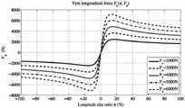
图4是轮胎纵向力与滑移率的关系图;Fig. 4 is the relation diagram of tire longitudinal force and slip ratio;
图5是轮胎纵向力与垂向力的关系图;Fig. 5 is the relation diagram of tire longitudinal force and vertical force;
图6是漂移控制系统开发流程示意图。Figure 6 is a schematic diagram of the development process of the drift control system.
具体实施方式Detailed ways
为详细说明本发明的技术内容、构造特点、实现目的等,下面结合附图对本发明进行全面解释。In order to describe in detail the technical content, structural features, realization purpose, etc. of the present invention, the present invention will be fully explained below with reference to the accompanying drawings.
本发明的总体工作框架是采用切换控制的思想,如图1所示,一种智能电动汽车轨迹跟踪与运动控制方法,遵循以下步骤:The overall working framework of the present invention adopts the idea of switching control, as shown in FIG. 1 , a method for trajectory tracking and motion control of an intelligent electric vehicle, which follows the following steps:
步骤1:根据给定目标轨迹以及当前路况,判断车辆是否能够工作在侧向稳定范围内;若工作在稳定区域内,执行步骤2;若超出侧向稳定范围,执行步骤3;Step 1: According to the given target trajectory and the current road conditions, determine whether the vehicle can work within the lateral stability range; if it works within the stability range, go to Step 2; if it exceeds the lateral stability range, go to
步骤2:执行工作模式1,采用车辆轨迹跟踪与横摆稳定双闭环控制器进行车辆轨迹跟踪与稳定性控制,如图2所示:根据期望行驶轨迹以及车辆运动学模型,解算出车辆的期望航向角;建立三自由度车辆动力学模型,设计轨迹跟踪控制器,将车辆的期望航向角与上一时刻的航向角差值输入到轨迹跟踪控制器,求解得到前轮转角和纵向速度;采用模型预测控制算法设计横摆稳定控制器,并将轨迹跟踪控制器求解得到的前轮转角与纵向速度作为横摆稳定控制器的状态输入,再进行力矩分配,实现对智能车的控制。Step 2: Execute working mode 1, use vehicle trajectory tracking and yaw stabilization double closed-loop controller to perform vehicle trajectory tracking and stability control, as shown in Figure 2: Calculate the expected vehicle according to the expected driving trajectory and the vehicle kinematics model Heading angle; establish a three-degree-of-freedom vehicle dynamics model, design a trajectory tracking controller, input the difference between the expected heading angle of the vehicle and the heading angle at the previous moment into the trajectory tracking controller, and solve to obtain the front wheel rotation angle and longitudinal speed; use The model predictive control algorithm designs the yaw stabilization controller, and uses the front wheel angle and longitudinal speed obtained by the trajectory tracking controller as the state input of the yaw stabilization controller, and then performs torque distribution to realize the control of the smart car.
具体执行如下:The specific implementation is as follows:
步骤2.1:建立三自由度车辆动力学模型,设计轨迹跟踪控制器,将车辆的期望航向角与上一时刻的航向角差值输入到轨迹跟踪控制器,求解得到前轮转角和纵向速度。Step 2.1: Establish a three-degree-of-freedom vehicle dynamics model, design a trajectory tracking controller, input the difference between the desired heading angle of the vehicle and the heading angle at the previous moment into the trajectory tracking controller, and solve to obtain the front wheel angle and longitudinal speed.
①建立三自由度车辆动力学模型:① Establish a three-degree-of-freedom vehicle dynamics model:
在进行轨迹跟踪的过程中,期望的轨迹是以大地坐标系作为参考的,为了得到车辆在大地坐标系下的绝对位置,考虑车身坐标系与大地坐标系的转换关系,得到如下运动学方程:In the process of trajectory tracking, the desired trajectory is based on the geodetic coordinate system. In order to obtain the absolute position of the vehicle in the geodetic coordinate system, considering the conversion relationship between the body coordinate system and the geodetic coordinate system, the following kinematics equations are obtained:


式中:X为质心在大地坐标系下的横坐标,Y为质心在大地坐标系下的纵坐标,
建立三自由度车辆动力学方程:Establish the three-degree-of-freedom vehicle dynamics equation:

式中:vx、vy分别表示车辆的纵向速度和侧向速度;Flf、Flr分别表示为车辆前、后轮与轮胎的纵向刚度、滑移率有关的纵向力;Fcf、Fcr分别表示为车辆前、后轮与轮胎的侧偏刚度、侧偏角有关的侧向力;γ为车辆横摆角速度;a、b分别为车辆质心到前、后轴的距离;δf为前轮转角;Iz为转动惯量。In the formula: vx and vy represent the longitudinal and lateral speeds of the vehicle, respectively; Flf , Flr represent the longitudinal forces related to the longitudinal stiffness and slip rate of the front and rear wheels of the vehicle and the tires, respectively; Fcf , Fcr is the lateral force related to the cornering stiffness and side-slip angle of the front and rear wheels and tires of the vehicle, respectively; γ is the yaw rate of the vehicle; a and b are the distances from the center of mass of the vehicle to the front and rear axles, respectively; δf is Front wheel rotation angle; Iz is the moment of inertia.
轮胎的侧偏角:Slip angle of tires:


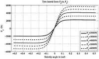
因此简化的轮胎力可以表示为公式(7),拟合曲线如图4,5所示:Therefore, the simplified tire force can be expressed as Equation (7), and the fitted curve is shown in Figures 4 and 5:

式中:Clf、Clr分别表示为车辆前、后轮胎的纵向刚度;Ccf、Ccr分别表示为车辆前、后轮胎的侧向刚度;sf、sr分别表示为车辆前、后轮胎的纵向滑移率。where Clf and Clr are the longitudinal stiffnesses of the front and rear tires of the vehicle, respectively; Ccf , Ccr are the lateral stiffnesses of the front and rear tires of the vehicle, respectively; sf , sr are the front and rear tires of the vehicle, respectively Longitudinal slip of the tire.
②设计轨迹跟踪控制器:②Design trajectory tracking controller:
得到面向轨迹跟踪控制器设计的控制模型:The control model for the trajectory tracking controller design is obtained:

在这里状态变量为

将式(8)整理得到预测模型的连续时间状态空间方程表达式如(9)所示:Arranging Equation (8) to obtain the continuous-time state space equation expression of the prediction model is shown in (9):

为了后续控制器的设计,将连续的状态空间模型离散化,选择采样时间为Ts=0.02s,离散化后的状态空间模型描述为式(10):For the subsequent controller design, the continuous state space model is discretized, the sampling time is selected as Ts =0.02s, and the state space model after discretization is described as formula (10):

本发明中定义预测时域为p,控制时域为m,p>m。车辆在[k+1,k+p]预测时域内动态可以基于车辆当前状态和预测模型得到。即在k+p时刻,车辆状态为:In the present invention, the prediction time domain is defined as p, and the control time domain is defined as m, where p>m. The vehicle dynamics in the [k+1,k+p] prediction time domain can be obtained based on the current state of the vehicle and the prediction model. That is, at time k+p, the vehicle state is:
x(k+p)=F(x(k),u(k),u(k+1),…,u(k+m),…,u(k+p-1))。当采样时间大于控制时域时,保持控制输入不变直到预测时域u(k+m-1)=u(k+m)=u(k+m+1)=…u(k+p-1)。x(k+p)=F(x(k),u(k),u(k+1),…,u(k+m),…,u(k+p-1)). When the sampling time is greater than the control time domain, keep the control input unchanged until the prediction time domain u(k+m-1)=u(k+m)=u(k+m+1)=…u(k+p- 1).
因此定义k时刻的最优控制输入:So define the optimal control input at time k:

相应的k时刻的预测输出The corresponding predicted output at time k

系统的参考输入序列定义如式(13)所示:The reference input sequence of the system is defined as equation (13):

在第k个采样时刻,y(k)作为控制系统预测的初始值,即y(k|k)=y(k)。被控系统的状态变量和输入会根据当前时刻的状态变量值和系统输入计算更新,将得出的控制序列的第一项作为系统输入作用于下一个时刻,并结合下一时刻被控系统的输出进行优化问题求解,如此反复就实现了控制序列的滚动优化,并对未来的时刻的状态进行了求解。At the kth sampling time, y(k) is used as the initial value predicted by the control system, that is, y(k|k)=y(k). The state variable and input of the controlled system will be calculated and updated according to the state variable value and system input at the current moment, and the first item of the obtained control sequence will be used as the system input to act on the next moment, and combined with the controlled system at the next moment. The output is used to solve the optimization problem. In this way, the rolling optimization of the control sequence is realized, and the state of the future time is solved.
②获得车辆的期望航向角:② Obtain the desired heading angle of the vehicle:
为了更好地跟踪轨迹,需要让纵向速度侧向速度,横摆角速度以及当前车辆位置跟踪上期望值,同时,控制动作不宜太大,得到车身控制器的目标函数如下式所示:In order to better track the trajectory, it is necessary to make the longitudinal velocity, lateral velocity, yaw angular velocity and the current vehicle position track the expected values. At the same time, the control action should not be too large. The objective function of the body controller is obtained as follows:
J=ΓQ||Y(k+1|k)-R(k+1)||2+ΓR||U(k)||2 (14)J=ΓQ ||Y(k+1|k)-R(k+1)||2 +ΓR ||U(k)||2 (14)
在这里ΓQ=diag(τQ1,τQ2,…,τQp)为控制车辆姿态的权重系数,ΓR=diag(τR1,τR2,…,τRp)为控制输入的权重系数。当ΓQ权重系数大的时候,系统侧重于考虑车辆的跟踪性能;ΓR相对较大时,系统侧重于考虑车辆的能量。Here ΓQ =diag(τQ1 ,τQ2 ,...,τQp ) is a weight coefficient for controlling vehicle attitude, and ΓR =diag(τR1 ,τR2 ,...,τRp ) is a weight coefficient for control input. When the weight coefficient of ΓQ is large, the system focuses on considering the tracking performance of the vehicle; when ΓR is relatively large, the system focuses on considering the energy of the vehicle.
步骤2.2:采用模型预测控制算法设计横摆稳定控制器,并将轨迹跟踪控制器求解得到的前轮转角与纵向速度作为横摆稳定控制器的状态输入,再进行力矩分配,实现对智能车的控制。Step 2.2: The yaw stabilization controller is designed by using the model predictive control algorithm, and the front wheel angle and longitudinal speed obtained by the trajectory tracking controller are used as the state input of the yaw stabilization controller, and then the torque is distributed to realize the intelligent vehicle. control.
本发明此部分主要基于车辆的横摆动力学进行研究,主要考虑车辆侧倾以及横摆两个自由度的运动。因此,在这里假定车速为定值,将车辆简化成为二自由度自行车模型,如图5所示。This part of the present invention is mainly based on the yaw dynamics of the vehicle, and mainly considers the motion of the two degrees of freedom of the vehicle roll and yaw. Therefore, the vehicle speed is assumed to be a fixed value here, and the vehicle is simplified to a two-degree-of-freedom bicycle model, as shown in Figure 5.
①二自由度车辆动力学模型搭建①Construction of two-degree-of-freedom vehicle dynamics model
如图3所示,车辆质心侧偏角和横摆角速度作为状态变量,四轮的驱动转矩和前轮转角作为输入,得到控制器模型。As shown in Figure 3, the vehicle mass center slip angle and yaw rate are used as state variables, and the four-wheel driving torque and front wheel angle are used as inputs to obtain the controller model.

其中,β是质心侧偏角,代表车辆纵轴与车速矢量方向之间的角度,γ是车身的横摆率。β和γ代表简化二自由度车辆动力学模型的两个自由度。Fyf,Fyr分别代表二自由度车辆模型前轮侧向力和后轮侧向力,m代表整车质量,V代表纵向车速,Lf,Lr分别代表车辆质心到前轴的距离和质心到后轴的距离。Mz是车辆横摆力矩,表达如下。where β is the center of mass slip angle, representing the angle between the longitudinal axis of the vehicle and the direction of the vehicle speed vector, and γ is the yaw rate of the vehicle body. β and γ represent the two degrees of freedom of the simplified two-degree-of-freedom vehicle dynamics model. Fyf , Fyr represent the front wheel lateral force and rear wheel lateral force of the two-degree-of-freedom vehicle model, m represents the vehicle mass, V represents the longitudinal vehicle speed, Lf , Lr represent the distance from the vehicle center of mass to the front axle and The distance from the center of mass to the rear axle. Mz is the vehicle yaw moment, expressed as follows.

其中,d代表单轴左右侧轮距,Fxij,i=f,r;j=l,r.代表左前轮、左后轮、右前轮和右后轮的纵向力。Among them, d represents the left and right wheel track of the single axle, Fxij , i=f,r; j=l,r. Represents the longitudinal force of the left front wheel, the left rear wheel, the right front wheel and the right rear wheel.
由于受纵向加速度、侧向加速度、侧倾以及俯仰等的影响,轮胎的垂向力负载可以描述为:Due to the influence of longitudinal acceleration, lateral acceleration, roll and pitch, etc., the vertical load of the tire can be described as:


其中,hcg代表车辆质心高度,g代表重力加速度,ax代表纵向加速,ay代表纵向加速度。Among them, hcg represents the height of the center of mass of the vehicle, g represents the acceleration of gravity, ax represents the longitudinal acceleration, and ay represents the longitudinal acceleration.
整理得到系统模型为:The system model after finishing is:

其中,FZ代表轮胎的垂向力负载,由公式(17)至(20)计算。where FZ represents the vertical force load of the tire, calculated from equations (17) to (20).
②基于公式(21)对横摆稳定控制器进行设计:②Design the yaw stabilization controller based on formula (21):
将公式(21)进行整理得到系统的状态空间模型:Arrange the formula (21) to get the state space model of the system:

将横摆角速度γ、质心侧偏角β作为系统的状态变量x=[β,γ]T,控制量为u=[δf,Tfl,Tfr,Trl,Trr]T分别为前轮转向角、四个车轮驱动电机的转矩命令,系统输出y=[β,γ]T。Take the yaw rate γ and the center of mass slip angle β as the state variables of the system x=[β, γ]T , and the control variables are u=[δf , Tfl , Tfr , Trl , Trr ]T are the front The steering angle of the wheel, the torque command of the four wheel drive motors, the system output y=[β,γ]T .
利用欧拉公式进行离散化,得到的离散时间系统模型如下:Using Euler's formula for discretization, the obtained discrete-time system model is as follows:

其中,k表示采样时刻,Ts为采样时间,矩阵
根据模型预测控制的基本原则和相关理论,可以推导出p步预测状态和预测输出:According to the basic principles of model predictive control and related theories, the p-step predicted state and predicted output can be deduced:


y(k+1|k)=C·x(k)y(k+1|k)=C·x(k)
(24)(twenty four)
MPC控制算法可以有效的解决多目标多约束问题,并且可将其表示为具有加权矩阵的多目标方程,并得到包括前轮转向角、四轮驱动力矩等多维优化变量。The MPC control algorithm can effectively solve the multi-objective and multi-constraint problem, and it can be expressed as a multi-objective equation with a weighted matrix, and the multi-dimensional optimization variables including front wheel steering angle and four-wheel drive torque can be obtained.
优化目标:optimize the target:
(a)为了保持车辆稳定和良好的操纵性,需要使得系统输出跟踪上期望模型,因此,主要的优化目标为(a) In order to maintain vehicle stability and good maneuverability, it is necessary to make the system output follow the desired model. Therefore, the main optimization objective is

式中Q1,Q2是优化目标中的加权系数。where Q1 , Q2 are the weighting coefficients in the optimization objective.
(b)电机转矩越大意味着从电池处消耗的能量就越大,减小消耗能量,控制量的平方和尽量小,(b) The greater the motor torque means, the greater the energy consumed from the battery. To reduce the energy consumption, the sum of the squares of the control quantities should be as small as possible.

式中R1,R2是优化目标中的加权系数。where R1 , R2 are the weighting coefficients in the optimization objective.
(c)为了减小控制动作的变化,保持平滑的转向和电机驱动行为,减小控制量的变化,(c) In order to reduce the change of control action, maintain smooth steering and motor drive behavior, reduce the change of control amount,

式中S1,S2是优化目标中的加权系数。where S1 , S2 are the weighting coefficients in the optimization objective.
电机饱和约束:Motor saturation constraints:

步骤3:执行工作模式2,采用双闭环控制结构进行对车辆轨迹跟踪的漂移控制:Step 3: Execute working mode 2, and use a double closed-loop control structure to perform drift control for vehicle trajectory tracking:
由于路面湿滑等因素,车辆以高速状态下进行急转弯时,不能保证侧向动力学的稳定,此时,车辆会产生强输入耦合和横摆/侧滑不稳定性,考虑侧向稳定的方法进行轨迹跟踪不可行。因此,在此工况下不再考虑车辆自身姿态,而是关注于对车辆轨迹的跟踪。尽管是完全在车辆稳定性极限范围外操纵的,漂移控制也可以同时实现对车辆侧滑和行驶路径两者的精确控制。自动驾驶漂移控制算法可以将车辆可用状态空间扩展到极限范围外,从而实现对车辆轨迹的跟踪。因此在此种工况下只考虑对轨迹的跟踪而不再追求车辆自身稳定性。Due to factors such as slippery road surface, when the vehicle makes sharp turns at high speed, the stability of lateral dynamics cannot be guaranteed. At this time, the vehicle will have strong input coupling and yaw/sideslip instability. Considering the stability of lateral stability method for trajectory tracking is not feasible. Therefore, in this working condition, the attitude of the vehicle itself is no longer considered, but the tracking of the vehicle trajectory is focused. Drift control enables precise control of both the vehicle's sideslip and travel path at the same time, despite being maneuvered entirely outside the vehicle's stability limits. The autonomous driving drift control algorithm can extend the available state space of the vehicle beyond the limit range, so as to realize the tracking of the vehicle trajectory. Therefore, only the tracking of the trajectory is considered in this working condition, and the stability of the vehicle itself is no longer pursued.
步骤3.1:测试工程师通过驾驶模拟器与车辆动力学仿真软件结合的测试平台,在不同路面附着系数、不同半径的圆形道路上进行漂移操作。在执行这些操作期间,记录车辆的轮胎数据以及前轮转角数据等车辆状态信息,并用于构建训练数据集。这些被后处理用于训练漂移控制下的车辆动力学模型和轮胎模型。Step 3.1: The test engineer conducts drifting operations on circular roads with different road adhesion coefficients and different radii through the test platform combining the driving simulator and the vehicle dynamics simulation software. During these operations, vehicle status information such as tire data and front wheel angle data are recorded and used to construct a training dataset. These are post-processed to train vehicle dynamics models and tire models under drift control.
本发明以一种路面附着系数(冰雪路面)为例,给出训练数据过程,训练数据集是通过直接串联在上述虚拟测试环境运行生成的。漂移状态(|β|≈30–40度)在几秒钟后达到,并在其余测试期间保持不变。首先,在不同半径的圆中进行漂移操作,R=[10:10:100]。此后,为了便于将所提出的系统推广到其他质心侧偏角范围的漂移控制,针对另外两组质心侧偏角范围重复了这些测试:中度漂移|β|≈15-25度,轻度漂移|β|≈10-15度。完成数据的采集及训练。The present invention takes a road surface adhesion coefficient (ice and snow road surface) as an example to give a training data process, and the training data set is generated by running in the above-mentioned virtual test environment directly in series. The drift state (|β| ≈ 30–40 degrees) was reached after a few seconds and remained unchanged for the rest of the test period. First, the drift operation is performed in circles of different radii, R=[10:10:100]. Thereafter, to facilitate generalization of the proposed system to drift control for other centroid sideslip ranges, these tests were repeated for two additional sets of centroid sideslip ranges: moderate drift |β|≈15-25 degrees, mild drift |β|≈10-15 degrees. Complete data collection and training.
步骤3.2:在完成数据训练后,对轮胎参数以及轮胎-道路摩擦系数进行拟合,计算在漂移状态下车辆质心位置变化,基于此建立新的用于对车辆轨迹进行跟踪的三自由度漂移控制动力学模型,设计轨迹跟踪控制器,将车辆的期望航向角与上一时刻的航向角差值输入到轨迹跟踪控制器,求解得到前轮转角和纵向速度,然后执行步骤2.2,对内环横摆稳定控制器的设计,实现车辆自身动力学的稳定性。Step 3.2: After completing the data training, fit the tire parameters and tire-road friction coefficient, calculate the position change of the center of mass of the vehicle in the drift state, and establish a new three-degree-of-freedom drift control for tracking the vehicle trajectory based on this Dynamic model, design a trajectory tracking controller, input the difference between the expected heading angle of the vehicle and the heading angle at the previous moment into the trajectory tracking controller, and solve to obtain the front wheel rotation angle and longitudinal speed, and then perform step 2. The design of the pendulum stability controller realizes the stability of the vehicle's own dynamics.
其中,利用转向角和后轴驱动力矩跟踪给定路径和期望质心侧偏角;选择了侧向位移误差和质心侧偏角作为控制变量,基于侧向位移误差和质心侧偏角的动力学分析,得到期望的航向角速度和综合的横摆角速度。Among them, the steering angle and the rear axle driving torque are used to track the given path and the expected center of mass slip angle; the lateral displacement error and the center of mass slip angle are selected as control variables, and the dynamic analysis based on the lateral displacement error and the center of mass slip angle is carried out. , to obtain the desired heading angular velocity and the integrated yaw angular velocity.
步骤3执行完毕后返回执行步骤1,依次循环,完成智能电动汽车轨迹跟踪与运动控制。After the execution of
Claims (7)
Translated fromChinese


Priority Applications (1)
| Application Number | Priority Date | Filing Date | Title |
|---|---|---|---|
| CN202010787928.4ACN111890951B (en) | 2020-08-07 | 2020-08-07 | Intelligent electric vehicle trajectory tracking and motion control method |
Applications Claiming Priority (1)
| Application Number | Priority Date | Filing Date | Title |
|---|---|---|---|
| CN202010787928.4ACN111890951B (en) | 2020-08-07 | 2020-08-07 | Intelligent electric vehicle trajectory tracking and motion control method |
Publications (2)
| Publication Number | Publication Date |
|---|---|
| CN111890951Atrue CN111890951A (en) | 2020-11-06 |
| CN111890951B CN111890951B (en) | 2022-08-05 |
Family
ID=73247182
Family Applications (1)
| Application Number | Title | Priority Date | Filing Date |
|---|---|---|---|
| CN202010787928.4AActiveCN111890951B (en) | 2020-08-07 | 2020-08-07 | Intelligent electric vehicle trajectory tracking and motion control method |
Country Status (1)
| Country | Link |
|---|---|
| CN (1) | CN111890951B (en) |
Cited By (34)
| Publication number | Priority date | Publication date | Assignee | Title |
|---|---|---|---|---|
| CN112578672A (en)* | 2020-12-16 | 2021-03-30 | 吉林大学青岛汽车研究院 | Unmanned vehicle trajectory control system based on chassis nonlinearity and trajectory control method thereof |
| CN112590774A (en)* | 2020-12-22 | 2021-04-02 | 同济大学 | Intelligent electric automobile drifting and warehousing control method based on deep reinforcement learning |
| CN112687121A (en)* | 2020-12-21 | 2021-04-20 | 苏州挚途科技有限公司 | Method and device for predicting driving track and automatic driving vehicle |
| CN112918490A (en)* | 2021-03-19 | 2021-06-08 | 吉林大学 | Trajectory tracking control strategy of distributed driving vehicle |
| CN112937571A (en)* | 2021-03-12 | 2021-06-11 | 北京理工大学 | Intelligent automobile track tracking control method and system |
| CN112937588A (en)* | 2021-04-01 | 2021-06-11 | 吉林大学 | Vehicle stability analysis method for ice and snow track road condition |
| CN113050651A (en)* | 2021-03-24 | 2021-06-29 | 无锡航者智能科技有限公司 | Time lag control method and system for tracking autonomous driving path of intelligent vehicle |
| CN113076596A (en)* | 2021-03-31 | 2021-07-06 | 同济大学 | Track following parallel prediction method fusing vehicle model and tire force curve |
| CN113076641A (en)* | 2021-03-31 | 2021-07-06 | 同济大学 | Intelligent vehicle-to-vehicle and computer-to-vehicle cooperative steering control parallel computing method based on risk assessment |
| CN113359457A (en)* | 2021-06-21 | 2021-09-07 | 清华大学 | High-dimensional dynamic model resolving device and method for intelligent vehicle chassis area controller |
| CN113386781A (en)* | 2021-05-24 | 2021-09-14 | 江苏大学 | Intelligent vehicle trajectory tracking control method based on data-driven vehicle dynamics model |
| CN113467470A (en)* | 2021-07-23 | 2021-10-01 | 西安理工大学 | Trajectory tracking control method of unmanned autonomous trolley |
| CN113671950A (en)* | 2021-07-28 | 2021-11-19 | 长安大学 | Vehicle trajectory tracking control method based on pose convergence algorithm |
| CN113867330A (en)* | 2021-05-11 | 2021-12-31 | 吉林大学 | A control method for vehicle drift under arbitrary paths based on a multi-degree-of-freedom prediction model |
| CN113928311A (en)* | 2021-10-29 | 2022-01-14 | 吉林大学 | A closed-loop switching control method for vehicle steady-state drift |
| CN113985868A (en)* | 2021-10-09 | 2022-01-28 | 北京科技大学 | Method for realizing hierarchical path tracking control of wheeled mobile robot |
| CN114148411A (en)* | 2021-12-16 | 2022-03-08 | 北京理工大学 | Drift control method of a wheeled unmanned platform |
| CN114261399A (en)* | 2021-11-24 | 2022-04-01 | 吉林大学 | Decision planning method for intelligent driving of automobile under ice and snow road surface |
| CN114379583A (en)* | 2021-12-10 | 2022-04-22 | 江苏大学 | A system and method for trajectory tracking of autonomous vehicles based on neural network dynamics model |
| CN114475584A (en)* | 2022-02-28 | 2022-05-13 | 中国第一汽车股份有限公司 | Obstacle avoidance control method and device for vehicle, vehicle and storage medium |
| CN114506327A (en)* | 2022-01-29 | 2022-05-17 | 重庆长安汽车股份有限公司 | Driver intention judgment system and method for vehicle drift control |
| CN114572191A (en)* | 2021-12-23 | 2022-06-03 | 桂林航天工业学院 | Independently-driven electric automobile trajectory tracking and stability integrated control method |
| CN114802200A (en)* | 2022-04-08 | 2022-07-29 | 合肥工业大学 | Method for tracking and controlling stability of tracks of intelligent automobile under extreme working conditions |
| CN115525054A (en)* | 2022-09-20 | 2022-12-27 | 武汉理工大学 | Large-scale industrial park unmanned sweeper edge path tracking control method and system |
| CN116461596A (en)* | 2023-04-12 | 2023-07-21 | 东风悦享科技有限公司 | Track tracking method, system and medium of multi-mode four-wheel independent steering system |
| CN116552550A (en)* | 2023-04-28 | 2023-08-08 | 贵州师范大学 | Vehicle track tracking control system based on parameter uncertainty and yaw stability |
| CN117389276A (en)* | 2023-11-05 | 2024-01-12 | 理工雷科智途(北京)科技有限公司 | Unmanned vehicle driving path tracking control method based on driving risk prediction |
| CN117622125A (en)* | 2024-01-12 | 2024-03-01 | 杭州世宝汽车方向机有限公司 | Path tracking control method based on differential steering |
| CN117863899A (en)* | 2024-01-25 | 2024-04-12 | 北京航空航天大学 | A vehicle control method for a distributed independent wheel angle drive-by-wire system |
| WO2024120066A1 (en)* | 2022-12-08 | 2024-06-13 | 广州导远电子科技有限公司 | Vehicle navigation method and device, electronic apparatus and readable storage medium |
| CN118605225A (en)* | 2024-08-08 | 2024-09-06 | 理工雷科智途(泰安)汽车科技有限公司 | A simulation test method based on vehicle position and state |
| CN118940497A (en)* | 2024-07-22 | 2024-11-12 | 南京林业大学 | Trajectory tracking method and system for three-degree-of-freedom vehicle model based on strong winds |
| CN119189988A (en)* | 2024-11-21 | 2024-12-27 | 华东交通大学 | A coordinated control method for path tracking and stability of electric vehicles |
| CN119898201A (en)* | 2024-12-23 | 2025-04-29 | 华南农业大学 | A method for controlling wheel transmission instability power redistribution in automobiles |
Citations (24)
| Publication number | Priority date | Publication date | Assignee | Title |
|---|---|---|---|---|
| ITMI952399A0 (en)* | 1995-11-21 | 1995-11-21 | ||
| JP2001134320A (en)* | 1999-11-01 | 2001-05-18 | Honda Motor Co Ltd | Lane tracking controller |
| EP2581258A1 (en)* | 2011-10-13 | 2013-04-17 | Siemens Aktiengesellschaft | Motor vehicle with at least one electric drive motor and method for operating a control device of a motor vehicle |
| DE102011089101A1 (en)* | 2011-12-20 | 2013-06-20 | Continental Automotive Gmbh | Method for detecting fault in drive train of machine of vehicle, involves impressing torque in drive train, where temporal course of actual-rotation angle of section of drive train is determined |
| DE102012217672A1 (en)* | 2012-09-27 | 2014-06-26 | Bayerische Motoren Werke Aktiengesellschaft | Method for adjusting yaw damping on two-lane two-axle motor vehicle, involves creating single-track model or model diagram for explaining steady state and transient lateral dynamics of double-track vehicle by accessing model parameters |
| CN104859650A (en)* | 2015-05-28 | 2015-08-26 | 吉林大学 | Multi-time scale rolling optimization control method for stability of vehicle yaw |
| US20160023654A1 (en)* | 2014-07-23 | 2016-01-28 | Mazda Motor Corporation | Driving-torque distribution control apparatus of four-wheel drive vehicle |
| US20160236679A1 (en)* | 2015-02-18 | 2016-08-18 | Toyota Jidosha Kabushiki Kaisha | Vehicle driving support control device |
| JP2017065322A (en)* | 2015-09-28 | 2017-04-06 | 本田技研工業株式会社 | Steering device for vehicle |
| CN107139917A (en)* | 2017-04-27 | 2017-09-08 | 江苏大学 | It is a kind of based on mix theory pilotless automobile crosswise joint system and method |
| US20180194349A1 (en)* | 2017-01-06 | 2018-07-12 | Toyota Research Institute, Inc. | Systems and methods for dynamically adjusting a vehicle trajectory according to deviations of a driver from expected inputs |
| CN108454623A (en)* | 2018-01-22 | 2018-08-28 | 大连理工大学 | A four-wheel independent drive unmanned electric vehicle trajectory tracking control method |
| US20180257631A1 (en)* | 2017-03-13 | 2018-09-13 | Ford Global Technologies, Llc | Methods and system providing vehicle drift |
| CN108909703A (en)* | 2018-06-27 | 2018-11-30 | 聊城大学 | A kind of determination method of the unstability controllable domain of automatic Pilot Emergency avoidance |
| CN108973769A (en)* | 2018-06-15 | 2018-12-11 | 吉林大学 | A kind of all fronts control electric car path tracking control method |
| CN109017760A (en)* | 2018-07-31 | 2018-12-18 | 大连民族大学 | Vehicle desired trajectory tracking, device and rolling time horizon optimization algorithm |
| CN109606352A (en)* | 2018-11-22 | 2019-04-12 | 江苏大学 | A Coordinated Control Method for Vehicle Path Tracking and Stability |
| CN109795502A (en)* | 2018-09-27 | 2019-05-24 | 吉林大学 | Path-following model predictive control method for smart electric vehicles |
| CN109976159A (en)* | 2019-04-09 | 2019-07-05 | 台州学院 | Intelligent vehicle crosswise joint method based on safely controllable domain |
| CN109969183A (en)* | 2019-04-09 | 2019-07-05 | 台州学院 | Curve following control method based on safety controllable domain |
| CN110395120A (en)* | 2019-08-14 | 2019-11-01 | 厦门金龙联合汽车工业有限公司 | A kind of weaving control method of four-wheel distribution driving car |
| CN110531750A (en)* | 2018-05-23 | 2019-12-03 | 百度(美国)有限责任公司 | The embedded LQR of PID for automatic driving vehicle |
| CN110605973A (en)* | 2019-09-18 | 2019-12-24 | 北京理工大学 | A multi-axis distributed electric drive vehicle handling stability control method based on layered structure |
| CN111391822A (en)* | 2020-03-27 | 2020-07-10 | 吉林大学 | A collaborative control method for vehicle lateral and longitudinal stability under extreme working conditions |
- 2020
- 2020-08-07CNCN202010787928.4Apatent/CN111890951B/enactiveActive
Patent Citations (24)
| Publication number | Priority date | Publication date | Assignee | Title |
|---|---|---|---|---|
| ITMI952399A0 (en)* | 1995-11-21 | 1995-11-21 | ||
| JP2001134320A (en)* | 1999-11-01 | 2001-05-18 | Honda Motor Co Ltd | Lane tracking controller |
| EP2581258A1 (en)* | 2011-10-13 | 2013-04-17 | Siemens Aktiengesellschaft | Motor vehicle with at least one electric drive motor and method for operating a control device of a motor vehicle |
| DE102011089101A1 (en)* | 2011-12-20 | 2013-06-20 | Continental Automotive Gmbh | Method for detecting fault in drive train of machine of vehicle, involves impressing torque in drive train, where temporal course of actual-rotation angle of section of drive train is determined |
| DE102012217672A1 (en)* | 2012-09-27 | 2014-06-26 | Bayerische Motoren Werke Aktiengesellschaft | Method for adjusting yaw damping on two-lane two-axle motor vehicle, involves creating single-track model or model diagram for explaining steady state and transient lateral dynamics of double-track vehicle by accessing model parameters |
| US20160023654A1 (en)* | 2014-07-23 | 2016-01-28 | Mazda Motor Corporation | Driving-torque distribution control apparatus of four-wheel drive vehicle |
| US20160236679A1 (en)* | 2015-02-18 | 2016-08-18 | Toyota Jidosha Kabushiki Kaisha | Vehicle driving support control device |
| CN104859650A (en)* | 2015-05-28 | 2015-08-26 | 吉林大学 | Multi-time scale rolling optimization control method for stability of vehicle yaw |
| JP2017065322A (en)* | 2015-09-28 | 2017-04-06 | 本田技研工業株式会社 | Steering device for vehicle |
| US20180194349A1 (en)* | 2017-01-06 | 2018-07-12 | Toyota Research Institute, Inc. | Systems and methods for dynamically adjusting a vehicle trajectory according to deviations of a driver from expected inputs |
| US20180257631A1 (en)* | 2017-03-13 | 2018-09-13 | Ford Global Technologies, Llc | Methods and system providing vehicle drift |
| CN107139917A (en)* | 2017-04-27 | 2017-09-08 | 江苏大学 | It is a kind of based on mix theory pilotless automobile crosswise joint system and method |
| CN108454623A (en)* | 2018-01-22 | 2018-08-28 | 大连理工大学 | A four-wheel independent drive unmanned electric vehicle trajectory tracking control method |
| CN110531750A (en)* | 2018-05-23 | 2019-12-03 | 百度(美国)有限责任公司 | The embedded LQR of PID for automatic driving vehicle |
| CN108973769A (en)* | 2018-06-15 | 2018-12-11 | 吉林大学 | A kind of all fronts control electric car path tracking control method |
| CN108909703A (en)* | 2018-06-27 | 2018-11-30 | 聊城大学 | A kind of determination method of the unstability controllable domain of automatic Pilot Emergency avoidance |
| CN109017760A (en)* | 2018-07-31 | 2018-12-18 | 大连民族大学 | Vehicle desired trajectory tracking, device and rolling time horizon optimization algorithm |
| CN109795502A (en)* | 2018-09-27 | 2019-05-24 | 吉林大学 | Path-following model predictive control method for smart electric vehicles |
| CN109606352A (en)* | 2018-11-22 | 2019-04-12 | 江苏大学 | A Coordinated Control Method for Vehicle Path Tracking and Stability |
| CN109976159A (en)* | 2019-04-09 | 2019-07-05 | 台州学院 | Intelligent vehicle crosswise joint method based on safely controllable domain |
| CN109969183A (en)* | 2019-04-09 | 2019-07-05 | 台州学院 | Curve following control method based on safety controllable domain |
| CN110395120A (en)* | 2019-08-14 | 2019-11-01 | 厦门金龙联合汽车工业有限公司 | A kind of weaving control method of four-wheel distribution driving car |
| CN110605973A (en)* | 2019-09-18 | 2019-12-24 | 北京理工大学 | A multi-axis distributed electric drive vehicle handling stability control method based on layered structure |
| CN111391822A (en)* | 2020-03-27 | 2020-07-10 | 吉林大学 | A collaborative control method for vehicle lateral and longitudinal stability under extreme working conditions |
Non-Patent Citations (3)
| Title |
|---|
| 倪兰青等: "基于预瞄的智能车辆路径跟踪控制研究", 《重庆理工大学学报(自然科学)》* |
| 李军等: "融合稳定性的高速无人驾驶车辆纵横向协调控制方法", 《交通运输工程学报》* |
| 柴瑞强等: "智能车辆轨迹跟踪控制器设计", 《软件导刊》* |
Cited By (51)
| Publication number | Priority date | Publication date | Assignee | Title |
|---|---|---|---|---|
| CN112578672B (en)* | 2020-12-16 | 2022-12-09 | 吉林大学青岛汽车研究院 | Unmanned vehicle trajectory control system and trajectory control method based on chassis nonlinearity |
| CN112578672A (en)* | 2020-12-16 | 2021-03-30 | 吉林大学青岛汽车研究院 | Unmanned vehicle trajectory control system based on chassis nonlinearity and trajectory control method thereof |
| CN112687121A (en)* | 2020-12-21 | 2021-04-20 | 苏州挚途科技有限公司 | Method and device for predicting driving track and automatic driving vehicle |
| CN112590774A (en)* | 2020-12-22 | 2021-04-02 | 同济大学 | Intelligent electric automobile drifting and warehousing control method based on deep reinforcement learning |
| CN112590774B (en)* | 2020-12-22 | 2022-02-18 | 同济大学 | A deep reinforcement learning-based drift storage control method for smart electric vehicles |
| CN112937571A (en)* | 2021-03-12 | 2021-06-11 | 北京理工大学 | Intelligent automobile track tracking control method and system |
| CN112918490A (en)* | 2021-03-19 | 2021-06-08 | 吉林大学 | Trajectory tracking control strategy of distributed driving vehicle |
| CN113050651A (en)* | 2021-03-24 | 2021-06-29 | 无锡航者智能科技有限公司 | Time lag control method and system for tracking autonomous driving path of intelligent vehicle |
| CN113076596A (en)* | 2021-03-31 | 2021-07-06 | 同济大学 | Track following parallel prediction method fusing vehicle model and tire force curve |
| CN113076641A (en)* | 2021-03-31 | 2021-07-06 | 同济大学 | Intelligent vehicle-to-vehicle and computer-to-vehicle cooperative steering control parallel computing method based on risk assessment |
| CN113076641B (en)* | 2021-03-31 | 2022-09-20 | 同济大学 | Intelligent vehicle-to-vehicle and computer-to-vehicle cooperative steering control parallel computing method based on risk assessment |
| CN112937588A (en)* | 2021-04-01 | 2021-06-11 | 吉林大学 | Vehicle stability analysis method for ice and snow track road condition |
| CN112937588B (en)* | 2021-04-01 | 2022-03-25 | 吉林大学 | Vehicle stability analysis method for ice and snow track road condition |
| CN113867330A (en)* | 2021-05-11 | 2021-12-31 | 吉林大学 | A control method for vehicle drift under arbitrary paths based on a multi-degree-of-freedom prediction model |
| CN113386781B (en)* | 2021-05-24 | 2024-05-24 | 江苏大学 | Intelligent vehicle track tracking control method based on data-driven vehicle dynamics model |
| CN113386781A (en)* | 2021-05-24 | 2021-09-14 | 江苏大学 | Intelligent vehicle trajectory tracking control method based on data-driven vehicle dynamics model |
| CN113359457A (en)* | 2021-06-21 | 2021-09-07 | 清华大学 | High-dimensional dynamic model resolving device and method for intelligent vehicle chassis area controller |
| CN113467470A (en)* | 2021-07-23 | 2021-10-01 | 西安理工大学 | Trajectory tracking control method of unmanned autonomous trolley |
| CN113467470B (en)* | 2021-07-23 | 2023-03-03 | 西安理工大学 | Trajectory tracking control method of unmanned autonomous trolley |
| CN113671950B (en)* | 2021-07-28 | 2024-02-02 | 长安大学 | A vehicle trajectory tracking control method based on pose convergence algorithm |
| CN113671950A (en)* | 2021-07-28 | 2021-11-19 | 长安大学 | Vehicle trajectory tracking control method based on pose convergence algorithm |
| CN113985868B (en)* | 2021-10-09 | 2023-08-08 | 北京科技大学 | Layered path tracking control implementation method for wheeled mobile robot |
| CN113985868A (en)* | 2021-10-09 | 2022-01-28 | 北京科技大学 | Method for realizing hierarchical path tracking control of wheeled mobile robot |
| CN113928311B (en)* | 2021-10-29 | 2024-04-19 | 吉林大学 | Closed-loop switching control method for steady-state drift of vehicle |
| CN113928311A (en)* | 2021-10-29 | 2022-01-14 | 吉林大学 | A closed-loop switching control method for vehicle steady-state drift |
| CN114261399A (en)* | 2021-11-24 | 2022-04-01 | 吉林大学 | Decision planning method for intelligent driving of automobile under ice and snow road surface |
| CN114261399B (en)* | 2021-11-24 | 2023-11-07 | 吉林大学 | Decision planning method for intelligent driving automobile under ice and snow road surface |
| CN114379583B (en)* | 2021-12-10 | 2024-05-14 | 江苏大学 | Automatic driving vehicle track tracking system and method based on neural network dynamics model |
| CN114379583A (en)* | 2021-12-10 | 2022-04-22 | 江苏大学 | A system and method for trajectory tracking of autonomous vehicles based on neural network dynamics model |
| CN114148411A (en)* | 2021-12-16 | 2022-03-08 | 北京理工大学 | Drift control method of a wheeled unmanned platform |
| CN114572191A (en)* | 2021-12-23 | 2022-06-03 | 桂林航天工业学院 | Independently-driven electric automobile trajectory tracking and stability integrated control method |
| CN114506327B (en)* | 2022-01-29 | 2023-10-27 | 重庆长安汽车股份有限公司 | Driver intention judging system and method for vehicle drift control |
| CN114506327A (en)* | 2022-01-29 | 2022-05-17 | 重庆长安汽车股份有限公司 | Driver intention judgment system and method for vehicle drift control |
| CN114475584A (en)* | 2022-02-28 | 2022-05-13 | 中国第一汽车股份有限公司 | Obstacle avoidance control method and device for vehicle, vehicle and storage medium |
| CN114475584B (en)* | 2022-02-28 | 2023-11-28 | 中国第一汽车股份有限公司 | Obstacle avoidance control method and device for vehicle, automobile and storage medium |
| CN114802200A (en)* | 2022-04-08 | 2022-07-29 | 合肥工业大学 | Method for tracking and controlling stability of tracks of intelligent automobile under extreme working conditions |
| CN115525054A (en)* | 2022-09-20 | 2022-12-27 | 武汉理工大学 | Large-scale industrial park unmanned sweeper edge path tracking control method and system |
| WO2024120066A1 (en)* | 2022-12-08 | 2024-06-13 | 广州导远电子科技有限公司 | Vehicle navigation method and device, electronic apparatus and readable storage medium |
| CN116461596A (en)* | 2023-04-12 | 2023-07-21 | 东风悦享科技有限公司 | Track tracking method, system and medium of multi-mode four-wheel independent steering system |
| CN116552550A (en)* | 2023-04-28 | 2023-08-08 | 贵州师范大学 | Vehicle track tracking control system based on parameter uncertainty and yaw stability |
| CN117389276A (en)* | 2023-11-05 | 2024-01-12 | 理工雷科智途(北京)科技有限公司 | Unmanned vehicle driving path tracking control method based on driving risk prediction |
| CN117389276B (en)* | 2023-11-05 | 2024-05-28 | 理工雷科智途(北京)科技有限公司 | Unmanned vehicle driving path tracking control method based on driving risk prediction |
| CN117622125A (en)* | 2024-01-12 | 2024-03-01 | 杭州世宝汽车方向机有限公司 | Path tracking control method based on differential steering |
| CN117863899A (en)* | 2024-01-25 | 2024-04-12 | 北京航空航天大学 | A vehicle control method for a distributed independent wheel angle drive-by-wire system |
| CN117863899B (en)* | 2024-01-25 | 2024-07-16 | 北京航空航天大学 | A vehicle control method for a distributed independent wheel angle drive-by-wire system |
| CN118940497A (en)* | 2024-07-22 | 2024-11-12 | 南京林业大学 | Trajectory tracking method and system for three-degree-of-freedom vehicle model based on strong winds |
| CN118605225A (en)* | 2024-08-08 | 2024-09-06 | 理工雷科智途(泰安)汽车科技有限公司 | A simulation test method based on vehicle position and state |
| CN119189988A (en)* | 2024-11-21 | 2024-12-27 | 华东交通大学 | A coordinated control method for path tracking and stability of electric vehicles |
| CN119189988B (en)* | 2024-11-21 | 2025-02-25 | 华东交通大学 | A coordinated control method for path tracking and stability of electric vehicles |
| CN119898201A (en)* | 2024-12-23 | 2025-04-29 | 华南农业大学 | A method for controlling wheel transmission instability power redistribution in automobiles |
| CN119898201B (en)* | 2024-12-23 | 2025-09-23 | 华南农业大学 | Wheel transmission instability power redistribution control method for automobile |
Also Published As
| Publication number | Publication date |
|---|---|
| CN111890951B (en) | 2022-08-05 |
Similar Documents
| Publication | Publication Date | Title |
|---|---|---|
| CN111890951B (en) | Intelligent electric vehicle trajectory tracking and motion control method | |
| CN109204317B (en) | Wheel hub drive electric automobile longitudinal, transverse and vertical force integrated control optimization method | |
| CN109318905B (en) | A hybrid control method for intelligent vehicle path tracking | |
| CN111873985B (en) | An integrated chassis control method for a four-wheel drive electric vehicle | |
| CN109552312A (en) | Intact stability model predictive control method | |
| CN113002324B (en) | Electronic differential system of four-wheel independent driving and independent steering electric automobile | |
| CN103921786B (en) | A kind of nonlinear model predictive control method of electric vehicle process of regenerative braking | |
| CN103057436B (en) | Yawing moment control method of individual driven electromobile based on multi-agent | |
| CN109795502A (en) | Path-following model predictive control method for smart electric vehicles | |
| CN111806427A (en) | A comprehensive control method for a four-wheel motor-driven vehicle | |
| CN108674414A (en) | A kind of intelligent automobile Trajectory Tracking Control method of limiting condition | |
| CN106515716A (en) | Coordinated control device and method for chassis integrated control system of wheel-driven electric vehicle | |
| CN113602278B (en) | Distributed model predictive path tracking control method for four-wheel independent drive electric vehicles | |
| Hu et al. | An optimal torque distribution control strategy for four-wheel independent drive electric vehicles considering energy economy | |
| CN115848162B (en) | Control method for six-wheel independent electrically-driven unmanned vehicle differential steering | |
| CN116424353B (en) | A coordinated control strategy for wire-controlled chassis subsystems based on distributed vehicles | |
| Shen et al. | Stability and maneuverability guaranteed torque distribution strategy of DDEV in handling limit: A novel LSTM-LMI approach | |
| CN114987537A (en) | Neural network dynamics-based road adaptive drift control system and method for automatic driving vehicle | |
| Li et al. | Adaptive sliding mode control of lateral stability of four wheel hub electric vehicles | |
| CN116512934A (en) | Torque distribution control method to realize energy consumption optimization of three-motor four-wheel drive electric vehicle | |
| CN118387086A (en) | Intelligent driving automobile track tracking stability control method | |
| CN116954083A (en) | Distributed collaborative control method and controller for autonomous vehicle chassis based on multi-agent theory | |
| Fu et al. | Anti-rollover control of heavy-duty dump truck with distributed model predictive control | |
| Laghmara et al. | Yaw moment lyapunov based control for in-wheel-motor-drive electric vehicle | |
| CN119176122B (en) | A reconfigurable distributed drive multi-axis vehicle trajectory tracking method and carrier device |
Legal Events
| Date | Code | Title | Description |
|---|---|---|---|
| PB01 | Publication | ||
| PB01 | Publication | ||
| SE01 | Entry into force of request for substantive examination | ||
| SE01 | Entry into force of request for substantive examination | ||
| GR01 | Patent grant | ||
| GR01 | Patent grant |