CN111885962A - Medical device comprising a sensor array and system for measuring - Google Patents
Medical device comprising a sensor array and system for measuringDownload PDFInfo
- Publication number
- CN111885962A CN111885962ACN201980020671.5ACN201980020671ACN111885962ACN 111885962 ACN111885962 ACN 111885962ACN 201980020671 ACN201980020671 ACN 201980020671ACN 111885962 ACN111885962 ACN 111885962A
- Authority
- CN
- China
- Prior art keywords
- carrier
- medical device
- elongated
- sensor
- ultrasound transducer
- Prior art date
- Legal status (The legal status is an assumption and is not a legal conclusion. Google has not performed a legal analysis and makes no representation as to the accuracy of the status listed.)
- Granted
Links
Images


Classifications
- A—HUMAN NECESSITIES
- A61—MEDICAL OR VETERINARY SCIENCE; HYGIENE
- A61B—DIAGNOSIS; SURGERY; IDENTIFICATION
- A61B8/00—Diagnosis using ultrasonic, sonic or infrasonic waves
- A61B8/44—Constructional features of the ultrasonic, sonic or infrasonic diagnostic device
- A61B8/4483—Constructional features of the ultrasonic, sonic or infrasonic diagnostic device characterised by features of the ultrasound transducer
- A61B8/4494—Constructional features of the ultrasonic, sonic or infrasonic diagnostic device characterised by features of the ultrasound transducer characterised by the arrangement of the transducer elements
- A—HUMAN NECESSITIES
- A61—MEDICAL OR VETERINARY SCIENCE; HYGIENE
- A61B—DIAGNOSIS; SURGERY; IDENTIFICATION
- A61B8/00—Diagnosis using ultrasonic, sonic or infrasonic waves
- A61B8/06—Measuring blood flow
- A—HUMAN NECESSITIES
- A61—MEDICAL OR VETERINARY SCIENCE; HYGIENE
- A61B—DIAGNOSIS; SURGERY; IDENTIFICATION
- A61B8/00—Diagnosis using ultrasonic, sonic or infrasonic waves
- A61B8/12—Diagnosis using ultrasonic, sonic or infrasonic waves in body cavities or body tracts, e.g. by using catheters
- A—HUMAN NECESSITIES
- A61—MEDICAL OR VETERINARY SCIENCE; HYGIENE
- A61B—DIAGNOSIS; SURGERY; IDENTIFICATION
- A61B8/00—Diagnosis using ultrasonic, sonic or infrasonic waves
- A61B8/08—Clinical applications
- A61B8/0891—Clinical applications for diagnosis of blood vessels
- A—HUMAN NECESSITIES
- A61—MEDICAL OR VETERINARY SCIENCE; HYGIENE
- A61B—DIAGNOSIS; SURGERY; IDENTIFICATION
- A61B8/00—Diagnosis using ultrasonic, sonic or infrasonic waves
- A61B8/44—Constructional features of the ultrasonic, sonic or infrasonic diagnostic device
- A61B8/4444—Constructional features of the ultrasonic, sonic or infrasonic diagnostic device related to the probe
- A61B8/445—Details of catheter construction
Landscapes
- Health & Medical Sciences (AREA)
- Life Sciences & Earth Sciences (AREA)
- Medical Informatics (AREA)
- Biophysics (AREA)
- Nuclear Medicine, Radiotherapy & Molecular Imaging (AREA)
- Pathology (AREA)
- Radiology & Medical Imaging (AREA)
- Engineering & Computer Science (AREA)
- Biomedical Technology (AREA)
- Heart & Thoracic Surgery (AREA)
- Physics & Mathematics (AREA)
- Molecular Biology (AREA)
- Surgery (AREA)
- Animal Behavior & Ethology (AREA)
- General Health & Medical Sciences (AREA)
- Public Health (AREA)
- Veterinary Medicine (AREA)
- Gynecology & Obstetrics (AREA)
- Hematology (AREA)
- Ultra Sonic Daignosis Equipment (AREA)
Abstract
Description
Translated fromChinese技术领域technical field
本发明涉及一种用于插入患者体内的医疗装置,该医疗装置终止于远侧部分中并且包括传感器阵列。The present invention relates to a medical device for insertion into a patient, the medical device terminating in a distal portion and comprising a sensor array.
本发明还涉及一种包括这种医疗装置的系统。The invention also relates to a system comprising such a medical device.
背景技术Background technique
在心血管疾病的诊断和治疗中,微创医疗装置(例如,导管和微导管)通常用于检查患者的心血管系统,以便检测异常,例如患者的心血管系统内的狭窄或其他畸形。在此类检查中,尤其有用的诊断参数是患者的心血管系统内的血流速度,因为血流速度的异常值提供了受检查的动脉中出现诸如狭窄等的异常的强烈指示。In the diagnosis and treatment of cardiovascular disease, minimally invasive medical devices (eg, catheters and microcatheters) are commonly used to examine a patient's cardiovascular system in order to detect abnormalities, such as strictures or other malformations within the patient's cardiovascular system. A particularly useful diagnostic parameter in such examinations is blood flow velocity within the patient's cardiovascular system, as abnormal values of blood flow velocity provide a strong indication of abnormalities such as stenosis in the examined artery.
为此,微创医疗装置可包括(中心)管腔,导丝可穿过该管腔被引导进入患者的动脉。已知这样的导丝的远侧末端装配有PZT超声换能器,该PZT超声换能器能够操作以用于在患者的动脉内执行多普勒超声测量,从多普勒超声测量结果中可以提取血流速度相关数据,例如受检查的血管中的峰值血流速度。To this end, a minimally invasive medical device may include a (central) lumen through which a guidewire may be guided into a patient's artery. The distal tip of such a guidewire is known to be equipped with a PZT ultrasound transducer operable for performing Doppler ultrasound measurements within a patient's arteries, from which Doppler ultrasound measurements can be obtained. Extract blood flow velocity related data, such as peak blood flow velocity in the vessel under examination.
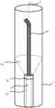
这种装置在图1中示意性地示出,其中医疗装置10插入患者的血管1中,在其远侧末端处包含PZT超声换能器62的导丝60穿过医疗装置10的中心管腔15插入到血管1中。然而,如图1所示,这样的操作并非没有问题。更具体而言,导丝60通常是柔性的,以利于导丝60被引导穿过患者的血管1。为此,导丝60的远侧末端相对于血管轴线并不具有良好限定的取向,这可能导致PZT超声换能器62与血管未对准,以至于使得PZT超声换能器62的视场64主要位于血管1的外部。因此,利用位于导丝60的远侧末端的PZT超声换能器62获得的血流速度测量值可能不可靠,尤其是在PZT超声换能器62的视场64与血管轴线未对准时。Such a device is shown schematically in FIG. 1 , wherein a
US 2010/0305451 A1和EP 2455133 A1描述了在医疗装置的远侧面处包括超声换能器的医疗装置。US 2010/0305451 A1 and EP 2455133 A1 describe medical devices comprising ultrasound transducers at the distal side of the medical device.
本发明的一个目的是改善医疗装置的可制造性和/或性能。It is an object of the present invention to improve the manufacturability and/or performance of medical devices.
发明内容SUMMARY OF THE INVENTION
本发明试图提供一种用于插入患者体内的可移动医疗装置,例如,微创医疗装置,它有助于可靠地确定患者的心血管系统内的血流相关参数。The present invention seeks to provide a removable medical device, eg, a minimally invasive medical device, for insertion into a patient that facilitates reliable determination of blood flow-related parameters within a patient's cardiovascular system.
本发明还试图提供一种用于控制这种医疗装置的系统。The present invention also seeks to provide a system for controlling such a medical device.
根据一个方面,提供了一种用于插入患者体内的医疗装置,该医疗装置包括界定管腔的管腔主体,该医疗装置终止在远侧部分中,并且还包括承载体,该承载体承载在所述远侧部分处被安装在所述管腔主体的前向边缘上的环形的超声换能器装置,使得所述环形超声换能器装置围绕所述管腔定位。According to one aspect, there is provided a medical device for insertion into a patient, the medical device comprising a lumen body defining a lumen, the medical device terminating in a distal portion, and a carrier carried on a An annular ultrasonic transducer device is mounted on the forward edge of the lumen body at the distal portion such that the annular ultrasonic transducer device is positioned around the lumen.
本发明基于这样的认识,即,这种医疗装置的远侧部分,例如,其远侧末端,具有比例如穿过其管腔馈送的导丝更大的刚度。而且,在介入操作之前,导丝末端通常由执业医生弯曲,以便使执业医生能够操纵导丝,(弯曲的)导丝的取向通常与血管的轴线未对准。另一方面,由于这种刚度,医疗装置的远侧末端更好地对准,该刚度部分上可以由导丝的一部分存在于管腔的在远侧末端中的那部分内来提供。因此,这样的远侧部分相对于被插入医疗装置的血管的轴线的取向比穿过其管腔馈送的柔性导丝的末端明显更稳定,使得超声换能器装置相对于血管轴线的取向,即超声换能器装置的视场,较不容易发生变化,并且与从这种超声换能器装置获取的数据得出的不可靠的血流相关参数确定值较少相关。通过使超声换能器装置围绕远侧部分中的管腔出口定向,物体或流体仍可以经过管腔进入患者的心血管系统,使得根据本发明的实施例的医疗装置的远侧末端处包括超声换能器装置并不损害其功能性。The present invention is based on the recognition that the distal portion of such a medical device, eg its distal tip, has a greater stiffness than eg a guide wire fed through its lumen. Also, prior to an interventional procedure, the guidewire tip is typically bent by a practitioner to enable the practitioner to maneuver the guidewire, the (bent) guidewire orientation typically being misaligned with the axis of the vessel. On the other hand, the distal tip of the medical device is better aligned due to this stiffness, which may in part be provided by a portion of the guide wire present within that portion of the lumen in the distal tip. Thus, the orientation of such a distal portion relative to the axis of the vessel into which the medical device is inserted is significantly more stable than the tip of a flexible guidewire fed through its lumen, such that the orientation of the ultrasound transducer device relative to the vessel axis, i.e. The field of view of an ultrasound transducer device is less prone to change and is less associated with unreliable blood flow related parameter determinations derived from data acquired from such an ultrasound transducer device. By orienting the ultrasound transducer device around the lumen outlet in the distal portion, objects or fluids can still enter the patient's cardiovascular system through the lumen, such that the medical device according to embodiments of the present invention includes ultrasound at the distal tip The transducer arrangement does not impair its functionality.
在本申请的上下文中,术语超声换能器装置是指包括至少一个超声换能器的超声换能器的集合,例如与管腔对准的环形超声换能器,使得管腔延伸穿过环形超声换能器及其承载体。In the context of this application, the term ultrasonic transducer device refers to a collection of ultrasonic transducers comprising at least one ultrasonic transducer, such as a ring-shaped ultrasonic transducer aligned with a lumen such that the lumen extends through the ring Ultrasonic transducer and its carrier.
在一些实施例中,环形超声换能器装置包括围绕管腔在空间上分布的多个超声换能器。例如,这在所获取的超声回波的信噪比方面可能是有利的,因为更多数量的超声换能器可以将更强的超声波束投射到医疗装置所插入的血管中。In some embodiments, the annular ultrasonic transducer device includes a plurality of ultrasonic transducers spatially distributed around the lumen. This may be advantageous, for example, in terms of the signal-to-noise ratio of the acquired ultrasound echoes, since a greater number of ultrasound transducers can project a stronger ultrasound beam into the blood vessel into which the medical device is inserted.
在特定实施例中,超声换能器是可单独寻址的。这具有以下优点:可以通过在不同的时间点和/或以不同的方式对相应的超声换能器进行单独的寻址,而以电子方式来控制所产生的超声波束的形状和方向。In certain embodiments, the ultrasound transducers are individually addressable. This has the advantage that the shape and direction of the generated ultrasound beam can be electronically controlled by individually addressing the corresponding ultrasound transducers at different points in time and/or in different ways.
超声换能器可相对于医疗装置的中心轴线倾斜,使得所述超声换能器远离所述中心轴线瞄准。这样具有的优点是,增加了利用超声换能器产生的超声波束的波束宽度,并且减少了来自穿过管腔插入到超声换能器的视场中的导丝的超声反射的干扰。还可以有利于基于利用超声换能器获得的多普勒频谱确定管腔的横截面积,并因此确定绝对流量。另外,倾斜角提供了对超声换能器装置的声学性能和波束宽度的控制。例如,可以使用较大的倾斜角来增加超声波束的宽度,而可以使用较小的倾斜角来增加血管的中心区域(即,在导丝周围)的声信号强度。The ultrasound transducer may be tilted relative to a central axis of the medical device such that the ultrasound transducer is aimed away from the central axis. This has the advantage of increasing the beam width of the ultrasound beam generated with the ultrasound transducer and reducing interference from ultrasound reflections from a guidewire inserted through the lumen into the field of view of the ultrasound transducer. It may also be advantageous to determine the cross-sectional area of the lumen, and thus the absolute flow, based on the Doppler spectrum obtained with the ultrasound transducer. Additionally, the tilt angle provides control over the acoustic performance and beamwidth of the ultrasonic transducer device. For example, larger tilt angles can be used to increase the width of the ultrasound beam, while smaller tilt angles can be used to increase the acoustic signal strength in the central region of the vessel (ie, around the guidewire).
在第一组实施例中,该承载体包括:主体,其被安装在医疗装置的管腔主体上;以及多个渐缩的柔性部分,其包括从所述主体延伸的硅岛,每个硅岛包括超声换能器装置的至少一个超声换能器,所述渐缩的柔性岛被折叠在管腔主体的所述前向边缘上。例如,可以使用所谓的柔性-刚性(F2R)技术来实现这种承载体,在柔性-刚性技术中,将承载电路部件(例如超声换能器)的刚性硅岛悬置在柔性聚合物基质(例如聚酰亚胺基质)中,该聚合物基质可以是多层的,使得连接到硅岛的电连接件在这类聚合物层之间延伸,该聚合物层通常由电绝缘聚合物制成,使得电连接件与外界电绝缘。通过这样的柔性布置结构,承载体可以以直接的方式被定位在医疗装置的管腔主体上,同时还利于超声换能器在与其中心轴线所成的倾斜角下的定向,如前所述。In a first set of embodiments, the carrier includes: a body mounted on a lumen body of a medical device; and a plurality of tapered flexible portions including silicon islands extending from the body, each silicon The island includes at least one ultrasound transducer of the ultrasound transducer arrangement, the tapered flexible island being folded over the forward edge of the lumen body. Such carriers can be realized, for example, using so-called flexible-rigid (F2R) technology, in which rigid silicon islands carrying circuit components (such as ultrasound transducers) are suspended in a flexible polymer matrix ( such as a polyimide matrix), the polymer matrix may be multi-layered such that electrical connections to the silicon islands extend between such polymer layers, typically made of electrically insulating polymers , so that the electrical connector is electrically insulated from the outside world. With such a flexible arrangement, the carrier can be positioned on the lumen body of the medical device in a direct manner, while also facilitating the orientation of the ultrasound transducer at an oblique angle to its central axis, as previously described.
在一个实施例中,该医疗装置还包括在医疗装置的长度方向上在管腔体上延伸的多个(导电)导线,所述导线中的每条导线被连接至所述硅岛之一。例如,这样的导线可以连接到硅岛的背侧,在这种情况下,例如,硅岛可以包括一个或多个贯穿硅通孔,该贯穿硅通孔将导线连接到位于硅岛的前侧的电路,例如,超声换能器。替代性地,导线可以连接到这种硅岛的侧表面,在硅岛的侧表面上可以存在用于将导线连接到这种电路的触点。In one embodiment, the medical device further comprises a plurality of (conductive) wires extending over the lumen body in the length direction of the medical device, each of the wires being connected to one of the silicon islands. For example, such wires may be connected to the backside of the silicon island, in which case, for example, the silicon island may include one or more through silicon vias that connect the wires to the front side of the silicon island circuits, for example, ultrasound transducers. Alternatively, wires may be connected to the side surfaces of such silicon islands on which there may be contacts for connecting wires to such circuits.
代替多个硅岛,承载体可以包括环形圈,该环形圈承载超声换能器装置,例如,一个或多个超声换能器。环形圈可装配在管腔周围,使得管腔延伸穿过环形圈,并且可以是刚性的,例如,硅环形圈,其具有易于制造的优点。Instead of a plurality of silicon islands, the carrier may comprise an annular ring carrying an ultrasonic transducer arrangement, eg, one or more ultrasonic transducers. The annular ring can fit around the lumen such that the lumen extends through the annular ring, and can be rigid, eg, a silicon annular ring, which has the advantage of being easy to manufacture.
这样的承载体还可包括在医疗装置的管腔主体上的至少一个触点,以及在该至少一个触点和超声换能器装置之间的柔性连接件,以及被连接到该至少一个触点并在医疗装置的长度方向上在管腔主体上延伸的(导电)导线。这有助于超声换能器装置的连接性,因为一个或多个触点可以被定位在管腔主体上,而柔性连接件确保环形圈可以围绕管腔被折叠在管腔主体的前向边缘上。Such a carrier may also include at least one contact on the lumen body of the medical device, and a flexible connection between the at least one contact and the ultrasound transducer device, and be connected to the at least one contact and a (conductive) wire extending on the lumen body in the length direction of the medical device. This facilitates the connectivity of the ultrasound transducer device as one or more contacts can be positioned on the lumen body, while the flexible connector ensures that the annular ring can be folded around the lumen at the forward edge of the lumen body superior.
替代性地,承载体包括双壁壳体,环形圈被容纳在该双壁壳体中,所述壳体包括围绕管腔主体装配的外壁。这种双壁壳体可包括内壁和外壁,超声换能器装置被定位在它们之间,例如,呈环形基板的形式。当超声换能器装置包括一个或多个PZT(锆钛酸铅;(Pb[Zr(x)Ti(1-x)]O3)元件时,这尤其适用。Alternatively, the carrier includes a double-walled housing in which the annular ring is housed, the housing including an outer wall fitted around the lumen body. Such a double-walled housing may comprise an inner wall and an outer wall between which the ultrasonic transducer device is positioned, eg in the form of an annular base plate. This is especially true when the ultrasonic transducer device comprises one or more PZT (lead zirconate titanate; (Pb[Zr(x) Ti(1-x) ]O3 ) elements.
在另一组实施例中,超声换能器装置包括一个或多个CMUT(电容式微机械超声换能器)元件或PMUT(压电式微机械超声换能器)元件。由于其优异的声学特性,尤其优选使用CMUT元件。其他超声换能器技术,例如单晶换能器,也可以被设想到。In another set of embodiments, the ultrasound transducer device comprises one or more CMUT (capacitive micromachined ultrasound transducer) elements or PMUT (piezoelectric micromachined ultrasound transducer) elements. The use of CMUT elements is especially preferred due to their excellent acoustic properties. Other ultrasonic transducer technologies, such as single crystal transducers, are also contemplated.
该医疗装置还可包括位于医疗装置的远侧部分的外表面上且在超声换能器装置近侧的压力传感器和成像元件中的至少一种。这可以帮助利用医疗装置获取更多的诊断相关信息。The medical device may also include at least one of a pressure sensor and an imaging element on an outer surface of the distal portion of the medical device and proximal to the ultrasound transducer device. This can help to obtain more diagnostically relevant information with medical devices.
例如,在医疗装置还包括压力传感器的情况下,这使得能够同时确定血流速度参数和血压,这可以有助于评估与血管的局部变窄和微循环相关的阻力。而且,使用血压和速度信息两者,可以确定脉搏波速度,这对于用于肾脏去神经术的患者分层可能是有用的。For example, where the medical device also includes a pressure sensor, this enables the simultaneous determination of blood flow velocity parameters and blood pressure, which can aid in the assessment of resistance associated with local narrowing of blood vessels and microcirculation. Also, using both blood pressure and velocity information, pulse wave velocity can be determined, which may be useful for patient stratification for renal denervation procedures.
在医疗装置还包括成像元件(例如,超声换能器元件或光学元件)的情况下,这种成像元件可以提供解剖学信息以及血流速度(和血压)测量值。例如,这使得能够确定绝对血流速度,这在例如测量心输出量方面是有益的。Where the medical device further includes imaging elements (eg, ultrasound transducer elements or optical elements), such imaging elements can provide anatomical information as well as blood flow velocity (and blood pressure) measurements. This enables, for example, the determination of absolute blood flow velocity, which is beneficial in eg measuring cardiac output.
根据本发明的实施例的医疗装置可以是导管,优选地是微导管。在本发明的上下文中,微导管是适合于插入患者的心血管系统中的导管,并且由于这个原因,其可以具有小于1mm的外径。在一些实施例中,微导管能够作为输注导管操作,例如,将血管活性剂或栓塞剂输注入患者体内。这样具有的优点是,超声换能器装置可用于监测这类药剂的输注速度,从而提高输注过程的精度并潜在地减轻患者的不适感。在栓塞的情况下,可以使用这种监视来检测栓塞剂回流的发生,这提供了有关何时停止栓塞操作的准确信号。The medical device according to an embodiment of the present invention may be a catheter, preferably a microcatheter. In the context of the present invention, a microcatheter is a catheter suitable for insertion into the cardiovascular system of a patient and for this reason may have an outer diameter of less than 1 mm. In some embodiments, the microcatheter is capable of operating as an infusion catheter, eg, to infuse a vasoactive or embolic agent into a patient. This has the advantage that an ultrasonic transducer device can be used to monitor the infusion rate of such medicaments, thereby increasing the accuracy of the infusion process and potentially reducing patient discomfort. In the case of embolization, this monitoring can be used to detect the occurrence of embolic agent backflow, which provides an accurate signal as to when to stop the embolization procedure.
根据另一方面,提供了一种系统,该系统包括本文描述的实施例中的任一个的医疗装置和适于至少在多普勒超声模式下控制该医疗装置的超声换能器装置的控制单元。这样的系统可以用于在将医疗装置插入到患者的心血管系统(例如,血管)中时准确地确定患者的血流相关参数。According to another aspect, there is provided a system comprising the medical device of any of the embodiments described herein and a control unit adapted to control an ultrasound transducer device of the medical device at least in a Doppler ultrasound mode . Such a system can be used to accurately determine a patient's blood flow related parameters when inserting a medical device into a patient's cardiovascular system (eg, blood vessel).
在一个实施例中,超声换能器装置包括多个可单独寻址的超声换能器元件,并且控制单元适于针对每个超声换能器元件从利用所述超声换能器元件获得的超声数据确定峰值血流速度;以及根据所确定的峰值血流速度,以电子方式操纵由多个可单独寻址的超声换能器元件产生的超声波束。通过使用由相应的超声换能器元件确定的相应的峰值血流速度,可以确定医疗装置在患者血管内的对准,基于此,可以使用电子波束操纵来优化超声换能器装置的操作。In one embodiment, the ultrasound transducer arrangement comprises a plurality of individually addressable ultrasound transducer elements and the control unit is adapted for each ultrasound transducer element from ultrasound obtained with said ultrasound transducer element The data determines a peak blood flow velocity; and electronically manipulates an ultrasound beam generated by a plurality of individually addressable ultrasound transducer elements based on the determined peak blood flow velocity. Using the respective peak blood flow velocities determined by the respective ultrasound transducer elements, the alignment of the medical device within the patient's blood vessel can be determined, based on which electronic beam steering can be used to optimize the operation of the ultrasound transducer device.
附图说明Description of drawings
参考附图,通过非限制性示例更详细地描述本发明的实施例,其中:Embodiments of the present invention are described in more detail by way of non-limiting example with reference to the accompanying drawings, wherein:
图1示意性地示出了被插入患者血管内的现有技术的微创医疗装置的剖视图;Figure 1 schematically shows a cross-sectional view of a prior art minimally invasive medical device inserted into a patient's blood vessel;
图2示意性地示出了被插入患者血管内的根据示例性实施例的微创医疗装置的剖视图;2 schematically illustrates a cross-sectional view of a minimally invasive medical device according to an exemplary embodiment inserted into a blood vessel of a patient;
图3示意性地示出了根据一个实施例的用于安装在医疗装置上的承载体的俯视图;Figure 3 schematically shows a top view of a carrier for mounting on a medical device according to one embodiment;
图4示意性地示出了根据一个实施例的用于安装在医疗装置上的承载体的仰视图;Figure 4 schematically illustrates a bottom view of a carrier for mounting on a medical device according to one embodiment;
图5示意性地示出了柔性-刚性制造方法;Figure 5 schematically illustrates a flexible-rigid fabrication method;
图6示意性地示出了根据一个实施例的用于将这种承载体组装到医疗装置上的组装方法;Figure 6 schematically illustrates an assembly method for assembling such a carrier onto a medical device according to one embodiment;
图7示意性地示出了根据另一示例性实施例的微创医疗装置的一方面的剖视图;7 schematically illustrates a cross-sectional view of an aspect of a minimally invasive medical device according to another exemplary embodiment;
图8示意性地示出了根据一个实施例的用于将另一承载体组装到医疗装置上的组装方法;Figure 8 schematically illustrates an assembly method for assembling another carrier to a medical device according to one embodiment;
图9示意性地示出了根据一个实施例的用于将另一承载体组装到医疗装置上的组装方法。Figure 9 schematically illustrates an assembly method for assembling another carrier to a medical device according to one embodiment.
图10示意性地示出了根据一个实施例的用于安装到医疗装置上的另一承载体的正视图;Figure 10 schematically illustrates a front view of another carrier for mounting to a medical device according to one embodiment;
图11示意性地示出了根据又一示例性实施例的微创医疗装置的一方面的剖视图;和Figure 11 schematically illustrates a cross-sectional view of an aspect of a minimally invasive medical device according to yet another exemplary embodiment; and
图12示意性地示出了根据一个实施例的包括微创医疗装置的系统。Figure 12 schematically illustrates a system including a minimally invasive medical device according to one embodiment.
具体实施方式Detailed ways
应当理解,附图仅是示意性的,并且没有按比例绘制。还应当理解,在所有附图中使用相同的附图标记来表示相同或类似的部件。It should be understood that the drawings are schematic only and are not drawn to scale. It should also be understood that the same reference numbers will be used throughout the drawings to refer to the same or like parts.
图2示意性地示出了在患者的血管1内原位的根据本发明的示例性实施例的医疗装置10。医疗装置10在其远侧末端处包括超声换能器装置50,使得超声换能器装置50的一个或多个超声换能器在远侧末端处环形地围绕医疗装置10的中心管腔15布置。该一个或多个超声换能器通常是面向前方的,使得一个或多个超声换能器的视场52(即,超声波束)延伸到在医疗装置10前方的血管1中。由于与可穿过医疗装置10的中心管腔15插入患者的血管1中的器械(例如,导丝60)相比,医疗装置10的主体具有较大的刚度,因此医疗装置10的主体与血管1的中心轴线3保持更好的对准。如以上所解释的,例如血管1内的导丝的未对准可能是由于其更柔性的性质以及预弯曲而引起的,但医疗装置10的远侧部分的更大的刚度部分上可能归因于延伸穿过管腔15的这种导丝的一部分的存在。因此,视场52基本上保持在患者的血管1内,使得经过血管1的患者血流的血流相关参数,例如(峰值)血流速度,由于医疗装置10相对于血管1的轴线3的取向的稳定性增加,因此例如可以通过超声换能器装置50的一个或多个超声换能器使用多普勒超声来更可靠地确定。Figure 2 schematically shows a
医疗装置10可以是导管,并且更优选地可以是具有一个或多个管腔15的微导管,诸如导丝的工具可以穿过该管腔15被插入(引导)到患者体内。替代性地,医疗装置10可以是输注导管,流体可以通过该输注导管经由管腔15或单独的管腔(未示出)被输注入患者的血管1中。在后一实施例中,超声换能器装置50可在多普勒模式下操作以便确定被输注入患者体内的流体的流动相关参数,例如流速的流向。这样的流体例如可以包括血管活性剂或栓塞剂,如本领域技术人员众所周知的。利用超声换能器装置50确定的被输注流体的流动相关参数可以用于量化已经被输注入患者体内的流体的量,使得这些参数可以用于确定何时可以终止输注操作。例如,在栓塞操作的情况下,超声换能器装置50可以用于确定栓塞剂的回流,其可以用作终止这种操作的指示。The
超声换能器装置50可以包括任何合适类型的超声换能器,例如压电式超声换能器或电容式超声换能器。压电式超声换能器的示例包括PZT元件和PMUT元件,而电容式超声换能器的示例包括CMUT元件。其他合适类型的超声换能器对技术人员来说将是明显的。
在下文中,将更详细地解释将超声换能器装置50集成到医疗装置10上的多个示例性实施例。然而,应理解的是,这些实施例并非旨在将本发明的保护范围仅限于这些实施例,并且基于本申请的教导对技术人员而言即刻明显的替代性实施例也旨在被涵盖。In the following, various exemplary embodiments of integrating the
在第一组实施例中,使用所谓的柔性-刚性技术提供承载体或组件20。图3示意性地示出了这种承载体20的俯视图,而图4示意性地示出了这种承载体20的仰视图。承载体20包括柔性主体22,多个指状件24从该柔性主体22延伸。如将在下面进一步详细解释的,指状件24在远离柔性主体22的方向上向内渐缩,使得当主体22围绕界定医疗装置10的中心管腔15的内壁折叠时,指状件24可以折叠在内壁的边缘上,从而在所述边缘上限定一个环。每个指状件24包括承载超声换能器元件51的至少一个硅岛27。在图3中,仅通过非限制性示例在每个指状件24上示出了两个这样的超声换能器51,这是因为应当理解,可以在指状件24上并入任何合适数量的这种超声换能器51,这将取决于内壁的边缘(如上所述,指状件24将折叠在其上)的厚度。In a first set of embodiments, the carrier or
在一个实施例中,承载体20还包括用作超声换能器元件51的触点的另外的硅岛26、28,它们从承载体的主体22的与指状件24相反的一侧延伸,导线71、73可以以任何合适的方式连接到该另外的硅岛26、28上,以便允许超声元件51和控制单元(未示出)之间的通信,例如,用于控制超声换能器元件51以及在超声换能器元件51和控制单元之间传输数据。通过延伸穿过承载体20的主体22的导电迹线,例如,铝迹线,触点26、28通常连接到承载超声换能器元件51的硅岛27。为此目的,主体22可以是多层的主体,其包括至少两个电绝缘的聚合物层,例如聚酰亚胺层,在它们之间形成这种导电迹线。为了避免疑问,应注意的是,仅以非限制性示例的方式示出了两个触点26、28,因为承载体20可以具有任何合适数量的这种触点以及与其连接的导线。In one embodiment, the
替代性地,尽管在附图中未示出,但是连接导线71、73可以延伸到承载超声换能器元件51的硅岛27,使得可以省略触点26、28。在这样的实施例中,导线71、73可以利用穿过硅岛将导线71、73连接到超声换能器元件51的贯穿硅通孔连接到这样的硅岛27的背侧,或者连接到这样的硅岛的侧表面,在该侧表面处可存在用于此类导线的着陆焊盘或触点。Alternatively, although not shown in the figures, the connecting
超声换能器元件51可以是可单独控制的或可单独寻址的,例如以允许对超声换能器元件51产生的超声波束进行电子波束操纵。超声换能器元件51可以在医疗装置10上的用于信号调节、模数转换、多路复用等的附近位置处电连接到专用集成电路(ASIC)。在一个实施例中,超声换能器元件51是CMUT元件,但是应当理解,替代性地,超声换能器元件51可以是PMUT元件或PZT元件。The
图5示出了形成连接两个硅岛的柔性箔桥的几个工艺步骤,该两个硅岛例如是其上设置有一个或多个超声换能器单元51的硅岛27,和承载触点26、28的硅岛。应理解的是,图5仅通过非限制性示例的方式提供了示例性的柔性-刚性工艺,并且就工艺步骤以及所使用的材料而言,该示例性工艺的许多变型对于本领域技术人员而言是即刻明显的,因此应当理解的是,使用这种柔性-刚性技术提供超声换能器装置50的医疗装置10的实施例不限于所示的方法和材料。Figure 5 shows several process steps for forming a flexible foil bridge connecting two silicon islands, such as
图5a)示出了具有在顶侧和底侧上生长的热二氧化硅层72的硅晶片70。图案化的铝区域81被溅射在顶侧上并且使用标准光刻术来图案化。聚酰亚胺74的图案化区域被放置在顶侧上的铝区域之一上,该图案限定了柔性箔中的桥。在连续的柔性箔的情况下,聚酰亚胺74可以是连续的片。铝层80沉积在聚酰亚胺74上,且第二聚酰亚胺层76放置在铝上。另一层铝82被图案化在铝层80上以用作蚀刻期间的掩模,所有这些如图5b)所示。最后,如图5c)所示,在硅岛位置88下方和柔性桥74、80、76下方,在被厚的阻止区域84所掩盖的区域之外的区域中,从背面蚀刻硅晶片70。在顶侧上的柔性桥90的任一侧上的聚酰亚胺层76被在蚀刻掩模层82的任一侧上图案化,然后蚀刻掩膜层82自身被蚀刻掉。结果是由柔性桥90连接的两个分离的硅岛92和94。柔性桥90和其他类似的桥使得能够将这样的超声换能器51填充的岛形成的阵列如前面解释的那样卷绕在医疗装置10的远侧末端上。Figure 5a) shows a
这在图6中更详细地示出,其中示意性地示出了这种承载体20被集成到医疗装置10的远侧部分上。如图6所示,承载体20的柔性主体22围绕医疗装置10的管腔主体12卷绕,从而界定一个或多个管腔,例如,中心管腔15,使得触点26、28(如果存在)和导线71、73被定位于管腔主体12上,导线71、73沿着管腔主体12在医疗装置10的长度方向上延伸。承载一个或多个超声换能器元件51的指状件24折叠在管腔主体12的前向边缘上,从而围绕中心管腔15的出口形成面向前方的环形超声换能器装置50,使得中心管腔15延伸穿过该超声换能器装置50,从而便于与超声换能器装置50结合使用诸如导丝60之类的器械。承载体20(或其至少一部分,例如主体22和/或指状件24)可以以任何合适的方式固定到管腔主体12,例如使用生物相容性粘合剂。随后,可以形成医疗装置10的外护套或外表面14,例如,通过涂覆等,以便将导线71、73和触点26、28嵌置在医疗装置10内,即在管腔主体12和外表面14之间。管腔主体12和外护套14可以是用任何合适的材料制成,例如任何合适的(生物相容性的)聚合物等。This is shown in more detail in FIG. 6 , where such a
图7以剖视图示意性地示出了根据本发明的替代性实施例的医疗装置10的远侧部分,其中管腔主体12的围绕管腔15的出口的前向边缘13相对于管腔15(或医疗装置10)的中心轴线17倾斜,使得该前向边缘13的表面法线远离该中心轴线17而成角度。因此,安装在管腔主体12的倾斜的前向边缘13上的超声换能器元件51,例如当在柔性-刚性承载体20的指状件24上时,远离该中心轴线17成角度,也就是利用包括超声换能器元件51的超声换能器装置50产生的超声波束的中心目标远离中心轴线17瞄准。7 schematically illustrates a distal portion of a
超声换能器元件51的这种倾斜取向具有许多优点。首先,在原位时,延伸超出管腔15的出口进入患者的血管1中的诸如导丝60的器械,由于该超声波束远离这种器械瞄准,而至少在该器械以差不多笔直的方式(即沿着中心轴线17)延伸入血管1时不太可能导致该器械与这种超声波束的干扰。其次,医疗装置10的具有这样的倾斜边缘13的远侧末端不太可能损坏血管1的壁,而第三,它便于确定管腔15的横截面积,使用利用超声换能器装置50获得的多普勒频谱可以从管腔15的横截面积得出绝对血流。如前所述,倾斜角提供了对超声换能器装置的声学性能和波束宽度的控制。例如,可以使用较大的倾斜角来增加超声波束的宽度,而可以使用较小的倾斜角来增加血管的中心区域(即,在导丝周围)的声信号强度。This oblique orientation of the
还应注意的是,超声换能器51的倾斜角不必与医疗装置10的外部倾斜角相同,例如,可以选择外部倾斜角,使得医疗装置10具有平滑的边缘以防止血管壁的穿孔或损坏,而超声换能器51的倾斜角可以更大,例如,更接近90°。It should also be noted that the inclination angle of the
图8示意性地示出了医疗装置10的另一实施例,其中,使用柔性-刚性技术来提供超声换能器装置50。在该实施例中,承载超声换能器装置50(即一个或多个超声换能器元件51)的刚性的环形承载体30,例如硅载体,通过柔性的铰链25(例如,聚酰亚胺铰链等)柔性地连接到触点26、28,如前所述,从触点26、28到一个或多个超声换能器元件51的导电连接件经过该柔性铰链。如前所述,在该实施例中,超声换能器元件51可以是任何合适的类型。柔性铰链25允许触点26、28如前所述被定位在管腔主体12上,同时刚性的环形承载体30被折叠到管腔主体12的前向边缘13上,之后可以在管腔主体12上形成外表面或外护套14,以完成医疗装置10,使得导线71、73在医疗装置10的长度方向上在管腔主体12和外表面14之间延伸,如前面所解释的。Figure 8 schematically illustrates another embodiment of a
应重申的是,通过非限制性示例示出了两个触点26、28和两条导线71、73,只是因为可以将任意合适数量的触点和导线定位在管腔主体12上。例如,在超声换能器元件51是可单独寻址的或被分组为由超声换能器元件51形成的可单独寻址的群组的实施例中,每个可单独寻址的元件群组可以经由单独的触点连接到单独的导线,如本领域技术人员将容易理解的那样。It should be reiterated that two
图9示意性地示出了医疗装置10的实施例,其中超声换能器装置50由包括一个或多个超声换能器元件51的环形基板53形成,该环形基板53被容纳在承载体40中,即在环形壳体中,该环形壳体具有环形的内壁42和环形的外壁44,环形的内壁42与管腔15对准,环形的内壁42和环形的外壁44之间容纳环形基板53。在该实施例中,环形基板53可以包括例如一个或多个PZT元件。环形基板53还可包括例如位于环形基板53的背侧的多个触点,一个或多个导线71、73可以连接到该多个触点,以利于超声换能器装置50与连接到医疗装置10的控制单元(未示出)之间的通信。替代性地,这样的触点可以设置在壳体40上,其中壳体还包括在这样的触点与环形基板53上的超声换能器装置50的一个或多个超声换能器元件之间的内部导电路径。FIG. 9 schematically shows an embodiment of the
至少壳体或承载体40的外壁44被设定尺寸,使得管腔主体12可以被装配在外壁44内,即,承载体40的外壁44可以紧密地装配在管腔主体12周围。还可以在外壁和管腔主体12之间施加粘合剂等,或者如果需要的话,可以使用任何其他合适的固定装置将承载体40固定到管腔主体12上。一旦将环形承载体40装配在医疗装置10的远侧末端,就如先前所解释的那样在管腔主体12上形成外表面或外护套14,以完成医疗装置10,使得一个或多个导线71、73沿医疗装置10的长度方向在管腔主体12及其外表面14之间延伸。At least the
环形基板53的整个面向前方的环形表面可以充当单个超声换能器,例如PZT超声换能器。替代性地,如图10中示意性地示出的,环形基板53的面向前方的环形表面可以被分割成多个这样的PZT超声换能器元件51或单独切割的单晶超声换能器元件51,在这种情况下,相应的PZT或单晶超声换能器元件51可以通过公共电极互连,例如,在将要同时操作PZT超声换能器元件51时。其他合适的(电极)装置对于技术人员将是即刻明显的。The entire forward facing annular surface of the
除了在医疗装置10的远侧末端处在管腔15的出口周围的面向前方的超声换能器装置50之外,在一些实施例中,医疗装置10还包括位于医疗装置10的外表面14上的压力传感器181和成像元件183中的至少一种,如图11中示意性地示出的。在本申请的上下文中,应当理解的是,在提到在外表面14上存在这样的压力传感器181和/或成像元件183的情况下,旨在包括其中这样的压力传感器181和/或成像元件183至少部分地嵌置在外表面14中或至少部分地被遮盖的实施例。这样的压力传感器181和/或成像元件183优选地被定位在医疗装置10的远侧部分处,靠近超声换能器装置50,使得利用各种传感器获得的数据涉及患者的血管1内的相同关注区域,例如,涉及到血管1的相同部分。In addition to the forward-facing
在医疗装置10的外表面上包括一个或多个压力传感器181使得能够(同时)确定血压和血流速度测量值两者,这例如有利于检测患者的血管1的关注区域(医疗装置10的远侧部分被设置在其中)中的局部变窄,以及量化这种异常的严重程度。另外,通过更新压力(P)和速度(V)信号,可以将脉搏波速度(PWV)确定为
下面的表I给出了利用现有技术的医疗装置和根据本发明的实施例的医疗装置10执行的血流测量的计算流体动力学(CFD)模拟的结果,其中如图1中示意性所示现有技术的医疗装置具有位于导丝60上的超声换能器装置,根据本发明的实施例的医疗装置10包括环形的超声换能器装置50,该环形的超声换能器装置50围绕在医疗装置10(这里是微导管)的远侧末端处的管腔15的出口。Table I below presents the results of computational fluid dynamics (CFD) simulations of blood flow measurements performed using a prior art medical device and a
表ITable I

CFD仿真表明,超声换能器装置50在医疗装置10的远侧末端而不是在导丝60上的定位不会显著影响在距超声换能器5mm的典型样本区域中的峰值血流速度(Vmax)测量值,同时在确定冠状动脉血流储备分数(CFR)方面获得了显著改善。这可以通过以下事实来解释:可以将更大数量的超声换能器装配到医疗装置10的远侧末端上,从而增加了声场强度并改善了信噪比。CFD simulations show that the positioning of the
图12示意性地示出了系统100,该系统100包括通过一个或多个导线71、73通信地联接到医疗装置10的控制单元110,例如用户控制台等。这种通信可以基于电信号,或替代性地,例如在US 2015/0335231 A1中公开的电光信号可以用于这种通信。为了避免疑问,应注意的是,不应将图12解释为比如示出了一个或多个导线71、73必定延伸超出医疗装置10到达控制单元110。当然,一个或多个导线71、73端接在位于医疗装置10的近端处的连接器装置中同样是可行的,其中控制单元110通过端接在互反的连接器装置中的线缆等连接到医疗装置10,该互反的连接器装置与医疗装置10的连接器装置连接。更一般地,可以在系统100的上下文中设想到控制单元110与医疗装置10之间的任何合适的连接。Figure 12 schematically shows a
控制单元110可包括处理器装置112,该处理器装置112包括一个或多个处理器,该一个或多个处理器被布置为控制医疗装置10的超声换能器装置50,例如,在超声换能器装置50包括可单独寻址的超声换能器元件51或由此类超声换能器元件51形成的可单独寻址的群组的情况下,以电子方式操纵超声换能器装置50的超声波束。处理器装置112通常还被布置为处理超声换能器装置50获得的(超声回波)信号。处理器装置112通常被布置为以多普勒模式(例如脉冲多普勒模式)操作超声换能器装置50,其中在第一时间间隔内超声换能器装置50以发射模式操作,在该模式中产生超声波束并将其发射到患者的血管1中,此后在第二时间间隔内,超声换能器装置50以接收模式操作,以接收来自所发射的超声波束的频移回波,该频移回波由处理器装置112处理,以便从接收到的频移超声回波信号,例如,从频移的量度,得出血流相关参数,例如血流速度,如众所周知的那样。The
替代性地,处理器装置112被布置成以连续波多普勒模式操作超声换能器装置50,其中第一组超声换能器元件51以发射模式操作,而第二组超声换能器元件51以接收模式同时操作。如本领域技术人员应理解的,这要求两组都可单独寻址。为了完整起见,应注意的是,连续波多普勒通常不允许确定在特定深度(即,距超声换能器装置50的特定距离)处的血流速度,而是沿整个询问线测量血流速度。因此,这在用户关注例如在比如狭窄的异常附近的局部血流相关参数的情形下不太合适,但是具有可以确定更高的血流速度的优点,例如,大约4m/s的速度,例如可能发生在患有主动脉瓣狭窄的患者中。在又一个实施例中,处理器装置112被布置成在脉冲多普勒模式和连续波多普勒模式之间切换超声换能器装置50的操作,以便获得局部血流相关参数,即,在距超声换能器装置50的确定深度处,以及沿着超声换能器装置50的整个询问线(景深)的血流相关参数。Alternatively, the
在超声换能器装置50包括多个可单独寻址的超声换能器元件51的情况下,处理器装置112可以实施一种算法,该算法从由每个可单独寻址的超声换能器元件51获得的频移回波推导出相应的峰值血流速度,以确定医疗装置10与患者的血管1的对准。基于所确定的医疗装置10与患者的血管1的对准,处理器装置112可以为可单独寻址的超声换能器元件51生成一组波束操纵信号,以改善超声换能器装置50的视场52与血管1的对准,即通过电子波束操纵来校正该视场52与血管1的未对准。In the event that the
控制单元110还可包括第一用户接口装置114,诸如监视器或显示器等,在其上将血流测量结果以及其他结果,例如在具有一个或多个血压传感器181的情况下的血压测量值以及在具有一个或多个图像传感器183的情况下的解剖学信息,呈现给用户。控制单元110还可包括第二用户接口装置116,诸如键盘、鼠标、轨迹球等,或者这样的用户输入装置的任意组合,用户可以通过第二用户接口装置116来控制医疗装置10的操作和处理由医疗装置10获取的数据,如众所周知的那样。第一用户接口装置114和第二用户接口装置116每个都可以与控制单元110集成在一起,或者可以是以有线或无线(例如,使用蓝牙等)方式连接到控制单元110的外围装置。第一用户接口装置114和第二用户接口装置116可以被集成到单个用户接口装置中,例如触摸屏。这样的控制单元110的实施例的许多其他变型对于技术人员而言将是即刻明显的,并且应当理解的是,对控制单元110的前述描述仅是通过非限制性示例的方式。可以设想到与根据本发明的实施例的医疗装置10一起使用的任何合适的控制单元110。The
应当注意的是,上述实施例例示说明而不是限制本发明,并且本领域技术人员将能够设计许多替代性实施例而不脱离所附权利要求的范围。在权利要求中,置于括号之间的任何附图标记不应解释为对权利要求的限制。词语“包括”并不排除权利要求中列出的元件或步骤之外的元件或步骤的存在。元件之前的词语“一”或“一个”并不排除存在多个这样的元件。可以借助于包括几个不同元件的硬件来实现本发明。在列举几个装置的装置权利要求中,这些装置中的几个可以由同一个硬件来体现。在互不相同的从属权利要求中记载某些措施的事实并不表示不能有利地使用这些措施的组合。It should be noted that the above-described embodiments illustrate rather than limit the invention, and that those skilled in the art will be able to design many alternative embodiments without departing from the scope of the appended claims. In the claims, any reference signs placed between parentheses shall not be construed as limiting the claim. The word "comprising" does not exclude the presence of elements or steps other than those listed in a claim. The word "a" or "an" preceding an element does not preclude the presence of a plurality of such elements. The present invention may be implemented by means of hardware comprising several different elements. In the device claim enumerating several means, several of these means may be embodied by one and the same item of hardware. The mere fact that certain measures are recited in mutually different dependent claims does not indicate that a combination of these measures cannot be used to advantage.
Claims (16)
Translated fromChineseApplications Claiming Priority (3)
| Application Number | Priority Date | Filing Date | Title |
|---|---|---|---|
| EP18163698.6AEP3542723A1 (en) | 2018-03-23 | 2018-03-23 | Medical device and system for blood flow measurement |
| EP18163698.6 | 2018-03-23 | ||
| PCT/EP2019/055938WO2019179795A1 (en) | 2018-03-23 | 2019-03-11 | Medical device comprising sensor array and system for measurements |
Publications (2)
| Publication Number | Publication Date |
|---|---|
| CN111885962Atrue CN111885962A (en) | 2020-11-03 |
| CN111885962B CN111885962B (en) | 2024-11-12 |
Family
ID=61768095
Family Applications (1)
| Application Number | Title | Priority Date | Filing Date |
|---|---|---|---|
| CN201980020671.5AActiveCN111885962B (en) | 2018-03-23 | 2019-03-11 | Medical device including sensor array and system for measuring |
Country Status (5)
| Country | Link |
|---|---|
| US (2) | US12220278B2 (en) |
| EP (2) | EP3542723A1 (en) |
| JP (1) | JP7480055B2 (en) |
| CN (1) | CN111885962B (en) |
| WO (1) | WO2019179795A1 (en) |
Cited By (1)
| Publication number | Priority date | Publication date | Assignee | Title |
|---|---|---|---|---|
| CN115281726A (en)* | 2022-08-05 | 2022-11-04 | 江苏霆升科技有限公司 | Circular Array Transducer and Forward Intracavitary Ultrasound Sheath |
Families Citing this family (4)
| Publication number | Priority date | Publication date | Assignee | Title |
|---|---|---|---|---|
| US11957319B2 (en)* | 2018-12-06 | 2024-04-16 | Verathon Inc. | Endobronchial ultrasound imaging |
| US20210177376A1 (en)* | 2019-12-16 | 2021-06-17 | Biosense Webster (Isreal) Ltd. | Guidewire ultrasound (us) probe for a minimally perturbing measurement of blood flow in brain vessel |
| US20240268789A1 (en)* | 2023-02-13 | 2024-08-15 | SoundCath, Inc. | Integrated steerable sheath ultrasonic imaging system and method |
| WO2025197075A1 (en)* | 2024-03-22 | 2025-09-25 | 朝日インテック株式会社 | Guide wire, torquer for elongated medical device, method for manufacturing guide wire, device for manufacturing guide wire, and blood vessel cross-sectional image display system |
Citations (13)
| Publication number | Priority date | Publication date | Assignee | Title |
|---|---|---|---|---|
| US4605009A (en)* | 1983-04-06 | 1986-08-12 | Universite Francois Rabelais | Ultrasonic sweep echography and display endoscopic probe |
| EP0626152A1 (en)* | 1993-05-28 | 1994-11-30 | Acuson Corporation | Compact rotationally steerable ultrasound transducer |
| CN1868409A (en)* | 2005-04-26 | 2006-11-29 | 韦伯斯特生物官能公司 | Display of catheter tip with beam direction for ultrasound system |
| CN101500492A (en)* | 2005-10-14 | 2009-08-05 | 伊西康内外科公司 | Medical ultrasound system and handpiece and methods for making and tuning |
| US20100305451A1 (en)* | 2009-05-29 | 2010-12-02 | Boston Scientific Scimed, Inc. | Systems and methods for making and using image-guided intravascular and endocardial therapy systems |
| US20120123270A1 (en)* | 2009-07-29 | 2012-05-17 | Koninklijke Philips Electronics N.V. | Device with integrated ultrasound transducers and flow sensor |
| EP2455133A1 (en)* | 2010-11-18 | 2012-05-23 | Koninklijke Philips Electronics N.V. | Catheter comprising capacitive micromachined ultrasonic transducers with an adjustable focus |
| CN102573983A (en)* | 2009-08-14 | 2012-07-11 | 伊西康内外科公司 | Ultrasonic surgical apparatus and silicon waveguide and methods for use thereof |
| CN104918555A (en)* | 2012-07-10 | 2015-09-16 | 富士胶片索诺声公司(美国) | Ultrasonic probe and aligned needle guide system |
| US20160029999A1 (en)* | 2014-08-01 | 2016-02-04 | Volcano Corporation | Intravascular Ultrasound Imaging Apparatus, Interface Architecture, and Method of Manufacturing |
| CN106132310A (en)* | 2014-03-26 | 2016-11-16 | 火山公司 | For using angled flow velocity sensing element to assess the device of blood vessel, system and method |
| CN106232017A (en)* | 2014-04-23 | 2016-12-14 | 皇家飞利浦有限公司 | Catheter with integrated controller for imaging and pressure sensing |
| CN107580474A (en)* | 2015-05-11 | 2018-01-12 | 皇家飞利浦有限公司 | Deformable Ultrasound Arrays and Systems |
Family Cites Families (13)
| Publication number | Priority date | Publication date | Assignee | Title |
|---|---|---|---|---|
| US7192400B2 (en) | 2002-10-24 | 2007-03-20 | Synovis Life Technologies, Inc. | Device and method for vascular monitoring |
| WO2005046443A2 (en) | 2003-11-07 | 2005-05-26 | Georgia Tech Research Corporation | Combination catheter devices, methods, and systems |
| US8303510B2 (en)* | 2005-07-01 | 2012-11-06 | Scimed Life Systems, Inc. | Medical imaging device having a forward looking flow detector |
| WO2009073752A1 (en)* | 2007-12-03 | 2009-06-11 | Kolo Technologies, Inc. | Ultrasound scanner built with capacitive micromachined ultrasonic transducers (cmuts) |
| EP2916720B1 (en) | 2012-11-08 | 2021-12-08 | Koninklijke Philips N.V. | An optical probe system |
| WO2014099797A2 (en)* | 2012-12-20 | 2014-06-26 | Jeremy Stigall | Catheter assembly with a shortened tip |
| US10022751B2 (en)* | 2014-05-30 | 2018-07-17 | Fujifilm Dimatix, Inc. | Piezoelectric transducer device for configuring a sequence of operational modes |
| US10792011B2 (en)* | 2015-06-23 | 2020-10-06 | Hemonitor Medical Ltd. | Systems and methods for hand-free continuous ultrasonic monitoring |
| US9883836B2 (en) | 2016-02-08 | 2018-02-06 | International Business Machines Corporation | Embedded device for flow monitoring |
| WO2017149421A1 (en) | 2016-03-03 | 2017-09-08 | Koninklijke Philips N.V. | Ultrasonic cmut transducer array with improved depth of field |
| JP2017164409A (en) | 2016-03-18 | 2017-09-21 | セイコーエプソン株式会社 | Ultrasonic probe |
| WO2018160657A1 (en)* | 2017-02-28 | 2018-09-07 | The Johns Hopkins University | Flexible control and guidance of minimally invasive focused ultrasound |
| CN111801052B (en)* | 2018-02-07 | 2024-06-07 | 西蒙医疗公司 | Ultrasound blood flow monitoring |
- 2018
- 2018-03-23EPEP18163698.6Apatent/EP3542723A1/ennot_activeWithdrawn
- 2019
- 2019-03-11JPJP2020550872Apatent/JP7480055B2/enactiveActive
- 2019-03-11EPEP19708563.2Apatent/EP3768170B1/enactiveActive
- 2019-03-11USUS17/040,217patent/US12220278B2/enactiveActive
- 2019-03-11WOPCT/EP2019/055938patent/WO2019179795A1/ennot_activeCeased
- 2019-03-11CNCN201980020671.5Apatent/CN111885962B/enactiveActive
- 2025
- 2025-01-23USUS19/034,815patent/US20250160793A1/enactivePending
Patent Citations (13)
| Publication number | Priority date | Publication date | Assignee | Title |
|---|---|---|---|---|
| US4605009A (en)* | 1983-04-06 | 1986-08-12 | Universite Francois Rabelais | Ultrasonic sweep echography and display endoscopic probe |
| EP0626152A1 (en)* | 1993-05-28 | 1994-11-30 | Acuson Corporation | Compact rotationally steerable ultrasound transducer |
| CN1868409A (en)* | 2005-04-26 | 2006-11-29 | 韦伯斯特生物官能公司 | Display of catheter tip with beam direction for ultrasound system |
| CN101500492A (en)* | 2005-10-14 | 2009-08-05 | 伊西康内外科公司 | Medical ultrasound system and handpiece and methods for making and tuning |
| US20100305451A1 (en)* | 2009-05-29 | 2010-12-02 | Boston Scientific Scimed, Inc. | Systems and methods for making and using image-guided intravascular and endocardial therapy systems |
| US20120123270A1 (en)* | 2009-07-29 | 2012-05-17 | Koninklijke Philips Electronics N.V. | Device with integrated ultrasound transducers and flow sensor |
| CN102573983A (en)* | 2009-08-14 | 2012-07-11 | 伊西康内外科公司 | Ultrasonic surgical apparatus and silicon waveguide and methods for use thereof |
| EP2455133A1 (en)* | 2010-11-18 | 2012-05-23 | Koninklijke Philips Electronics N.V. | Catheter comprising capacitive micromachined ultrasonic transducers with an adjustable focus |
| CN104918555A (en)* | 2012-07-10 | 2015-09-16 | 富士胶片索诺声公司(美国) | Ultrasonic probe and aligned needle guide system |
| CN106132310A (en)* | 2014-03-26 | 2016-11-16 | 火山公司 | For using angled flow velocity sensing element to assess the device of blood vessel, system and method |
| CN106232017A (en)* | 2014-04-23 | 2016-12-14 | 皇家飞利浦有限公司 | Catheter with integrated controller for imaging and pressure sensing |
| US20160029999A1 (en)* | 2014-08-01 | 2016-02-04 | Volcano Corporation | Intravascular Ultrasound Imaging Apparatus, Interface Architecture, and Method of Manufacturing |
| CN107580474A (en)* | 2015-05-11 | 2018-01-12 | 皇家飞利浦有限公司 | Deformable Ultrasound Arrays and Systems |
Cited By (1)
| Publication number | Priority date | Publication date | Assignee | Title |
|---|---|---|---|---|
| CN115281726A (en)* | 2022-08-05 | 2022-11-04 | 江苏霆升科技有限公司 | Circular Array Transducer and Forward Intracavitary Ultrasound Sheath |
Also Published As
| Publication number | Publication date |
|---|---|
| CN111885962B (en) | 2024-11-12 |
| JP7480055B2 (en) | 2024-05-09 |
| US20210007711A1 (en) | 2021-01-14 |
| EP3768170B1 (en) | 2023-07-12 |
| JP2021518230A (en) | 2021-08-02 |
| EP3768170A1 (en) | 2021-01-27 |
| EP3542723A1 (en) | 2019-09-25 |
| WO2019179795A1 (en) | 2019-09-26 |
| US20250160793A1 (en) | 2025-05-22 |
| US12220278B2 (en) | 2025-02-11 |
Similar Documents
| Publication | Publication Date | Title |
|---|---|---|
| CN111885962B (en) | Medical device including sensor array and system for measuring | |
| US20220240891A1 (en) | Catheter with integrated controller for imaging and pressure sensing | |
| CN104349714B (en) | Multiple Transducer Delivery Device | |
| EP3102098B1 (en) | Intravascular devices, systems, and methods having a core wire with embedded conductors | |
| US20160081657A1 (en) | Intravascular device for vessel measurement and associated systems, devices, and methods | |
| US20240023930A1 (en) | Multi-mode capacitive micromachined ultrasound transducer and associated devices, systems, and methods for multiple different intravascular sensing capabilities | |
| JP2017512566A (en) | Intravascular device, system, and method having a core wire formed from a plurality of materials | |
| US20140275950A1 (en) | Imaging guidewire with pressure sensing | |
| JP2011505205A (en) | Ultrasonic scanner constructed with capacitive micromachined ultrasonic transducer (CMUTS) | |
| JP2009500070A (en) | Medical imaging device with forward-facing flow detector | |
| US12138121B2 (en) | Device and method for intravascular imaging and sensing | |
| JP2021505292A (en) | Intraluminal ultrasound imaging device with substrate segment for control circuit | |
| US20230165559A1 (en) | Vessel measurement device and process | |
| EP3833249B1 (en) | Intraluminal device with capacitive pressure sensor | |
| JP2020516403A (en) | Ultrasonic transducer probe with facet distal front | |
| CN116133596A (en) | Curved circuit substrate for intraluminal ultrasound imaging assembly | |
| JP2025511952A (en) | Medical devices, sensors for medical devices, and related methods | |
| EP3656294A1 (en) | Capacitive pressure sensor for intraluminal guidewire or catheter |
Legal Events
| Date | Code | Title | Description |
|---|---|---|---|
| PB01 | Publication | ||
| PB01 | Publication | ||
| SE01 | Entry into force of request for substantive examination | ||
| SE01 | Entry into force of request for substantive examination | ||
| GR01 | Patent grant | ||
| GR01 | Patent grant |