CN111879740A - All-optical super-resolution microscopic device based on photon reset technology - Google Patents
All-optical super-resolution microscopic device based on photon reset technologyDownload PDFInfo
- Publication number
- CN111879740A CN111879740ACN202010671973.3ACN202010671973ACN111879740ACN 111879740 ACN111879740 ACN 111879740ACN 202010671973 ACN202010671973 ACN 202010671973ACN 111879740 ACN111879740 ACN 111879740A
- Authority
- CN
- China
- Prior art keywords
- scanning
- photon
- sample
- fluorescence
- reset
- Prior art date
- Legal status (The legal status is an assumption and is not a legal conclusion. Google has not performed a legal analysis and makes no representation as to the accuracy of the status listed.)
- Pending
Links
- 238000005516engineering processMethods0.000titleclaimsabstractdescription16
- 238000003384imaging methodMethods0.000claimsabstractdescription42
- 238000005286illuminationMethods0.000claimsabstractdescription37
- 230000005284excitationEffects0.000claimsabstractdescription29
- 230000003287optical effectEffects0.000claimsabstractdescription26
- 238000001514detection methodMethods0.000claimsabstractdescription16
- 238000000034methodMethods0.000claimsabstractdescription6
- 238000010869super-resolution microscopyMethods0.000claimsdescription7
- 230000008859changeEffects0.000claimsdescription3
- 230000008569processEffects0.000claimsdescription3
- 239000000523sampleSubstances0.000description30
- 230000000694effectsEffects0.000description4
- 238000001218confocal laser scanning microscopyMethods0.000description3
- 238000010586diagramMethods0.000description3
- 230000009471actionEffects0.000description2
- 230000008901benefitEffects0.000description2
- 230000006872improvementEffects0.000description2
- 230000015572biosynthetic processEffects0.000description1
- 238000004624confocal microscopyMethods0.000description1
- 238000005259measurementMethods0.000description1
- 238000003786synthesis reactionMethods0.000description1
Images


Classifications
- G—PHYSICS
- G01—MEASURING; TESTING
- G01N—INVESTIGATING OR ANALYSING MATERIALS BY DETERMINING THEIR CHEMICAL OR PHYSICAL PROPERTIES
- G01N21/00—Investigating or analysing materials by the use of optical means, i.e. using sub-millimetre waves, infrared, visible or ultraviolet light
- G01N21/62—Systems in which the material investigated is excited whereby it emits light or causes a change in wavelength of the incident light
- G01N21/63—Systems in which the material investigated is excited whereby it emits light or causes a change in wavelength of the incident light optically excited
- G01N21/64—Fluorescence; Phosphorescence
- G01N21/6402—Atomic fluorescence; Laser induced fluorescence
- G—PHYSICS
- G01—MEASURING; TESTING
- G01N—INVESTIGATING OR ANALYSING MATERIALS BY DETERMINING THEIR CHEMICAL OR PHYSICAL PROPERTIES
- G01N21/00—Investigating or analysing materials by the use of optical means, i.e. using sub-millimetre waves, infrared, visible or ultraviolet light
- G01N21/62—Systems in which the material investigated is excited whereby it emits light or causes a change in wavelength of the incident light
- G01N21/63—Systems in which the material investigated is excited whereby it emits light or causes a change in wavelength of the incident light optically excited
- G01N21/64—Fluorescence; Phosphorescence
- G01N21/645—Specially adapted constructive features of fluorimeters
- G01N21/6456—Spatial resolved fluorescence measurements; Imaging
- G01N21/6458—Fluorescence microscopy
- G—PHYSICS
- G02—OPTICS
- G02B—OPTICAL ELEMENTS, SYSTEMS OR APPARATUS
- G02B21/00—Microscopes
- G02B21/16—Microscopes adapted for ultraviolet illumination ; Fluorescence microscopes
- G—PHYSICS
- G02—OPTICS
- G02B—OPTICAL ELEMENTS, SYSTEMS OR APPARATUS
- G02B26/00—Optical devices or arrangements for the control of light using movable or deformable optical elements
- G02B26/08—Optical devices or arrangements for the control of light using movable or deformable optical elements for controlling the direction of light
- G02B26/10—Scanning systems
- G02B26/105—Scanning systems with one or more pivoting mirrors or galvano-mirrors
- G—PHYSICS
- G02—OPTICS
- G02B—OPTICAL ELEMENTS, SYSTEMS OR APPARATUS
- G02B27/00—Optical systems or apparatus not provided for by any of the groups G02B1/00 - G02B26/00, G02B30/00
- G02B27/58—Optics for apodization or superresolution; Optical synthetic aperture systems
- G—PHYSICS
- G01—MEASURING; TESTING
- G01N—INVESTIGATING OR ANALYSING MATERIALS BY DETERMINING THEIR CHEMICAL OR PHYSICAL PROPERTIES
- G01N21/00—Investigating or analysing materials by the use of optical means, i.e. using sub-millimetre waves, infrared, visible or ultraviolet light
- G01N21/62—Systems in which the material investigated is excited whereby it emits light or causes a change in wavelength of the incident light
- G01N21/63—Systems in which the material investigated is excited whereby it emits light or causes a change in wavelength of the incident light optically excited
- G01N21/64—Fluorescence; Phosphorescence
- G01N21/645—Specially adapted constructive features of fluorimeters
- G01N2021/6463—Optics
- G01N2021/6471—Special filters, filter wheel
- G—PHYSICS
- G01—MEASURING; TESTING
- G01N—INVESTIGATING OR ANALYSING MATERIALS BY DETERMINING THEIR CHEMICAL OR PHYSICAL PROPERTIES
- G01N21/00—Investigating or analysing materials by the use of optical means, i.e. using sub-millimetre waves, infrared, visible or ultraviolet light
- G01N21/62—Systems in which the material investigated is excited whereby it emits light or causes a change in wavelength of the incident light
- G01N21/63—Systems in which the material investigated is excited whereby it emits light or causes a change in wavelength of the incident light optically excited
- G01N21/64—Fluorescence; Phosphorescence
- G01N21/645—Specially adapted constructive features of fluorimeters
- G01N2021/6463—Optics
- G01N2021/6478—Special lenses
Landscapes
- Physics & Mathematics (AREA)
- General Physics & Mathematics (AREA)
- Optics & Photonics (AREA)
- Health & Medical Sciences (AREA)
- Chemical & Material Sciences (AREA)
- Analytical Chemistry (AREA)
- Nuclear Medicine, Radiotherapy & Molecular Imaging (AREA)
- Life Sciences & Earth Sciences (AREA)
- Biochemistry (AREA)
- General Health & Medical Sciences (AREA)
- Immunology (AREA)
- Pathology (AREA)
- Microscoopes, Condenser (AREA)
Abstract
Translated fromChinese
Description
Translated fromChinese技术领域technical field
基于光子复位技术的全光学超分辨显微装置属于光学显微测量领域,具体而言,涉及一种利用光子重新分配原理,借助全光学的手段实现高分辨率的显微成像装置。An all-optical super-resolution microscope device based on photon reset technology belongs to the field of optical microscope measurement, and specifically relates to a high-resolution microscopic imaging device that utilizes the principle of photon redistribution and uses all-optical means.
背景技术Background technique
激光扫描共聚焦显微镜(CLSM)因具有光学切片能力和高的成像对比度而在生物医学检测领域应用广泛。作为一种研究成熟的荧光显微镜,CLSM优秀的成像特性是通过使用具有较高动态范围的探测器和设置共焦探测针孔来实现的。在普通的CLSM中,每个扫描点的探测强度值通过积分探测器来记录,如光电倍增管(PMT)、雪崩光电二极管等;针孔与激发焦点位置同轴共轭,通过将检测到的光照强度赋给相应的激励扫描的位置,从而构造出相应的图像。此后,有研究表明,应用离轴针孔可以进一步提高分辨率。由于面阵探测器存在多个离轴像素点,且有研究表明样品上荧光发射光源的实际位置在激光的焦点和偏离光轴的探测点间的1/2处,在最终图像合成时,结合每个激发扫描位置拍摄到的针孔平面图像及其位置信息。借助面阵探测器和以上的光子复位算法可实现传统显微镜分辨率的提高。Laser scanning confocal microscopy (CLSM) is widely used in biomedical detection due to its optical sectioning capability and high imaging contrast. As a well-established fluorescence microscope, the excellent imaging properties of CLSM are achieved by using detectors with high dynamic range and setting confocal probe pinholes. In ordinary CLSM, the detection intensity value of each scanning point is recorded by integrating detectors, such as photomultiplier tubes (PMT), avalanche photodiodes, etc.; the pinhole is coaxially conjugated to the excitation focus position, and the detected The illumination intensity is assigned to the position of the corresponding excitation scan, thereby constructing the corresponding image. Since then, studies have shown that applying off-axis pinholes can further improve resolution. Since there are multiple off-axis pixel points in the area array detector, and studies have shown that the actual position of the fluorescence emission light source on the sample is halfway between the focal point of the laser and the detection point deviated from the optical axis, in the final image synthesis, combined with Pinhole plane images and their location information captured at each excitation scan position. With the help of area array detectors and the above photon reset algorithm, an increase in the resolution of conventional microscopes can be achieved.
遵循以上原理,有学者提出了图像扫描显微镜,即将激光扫描共聚焦显微镜中作为探测器的光电倍增管(PMT)替换为面阵探测器CCD,基于以上光子复位原理,在后续计算机图像处理中,对探测器的离轴像素点采集到的图像进行移位,即将探测图像移位至激光的焦点和偏离光轴的探测点间距离为一半的位置处,将面阵探测器上每个像素点探测到的光子重新分配到准确位置,对所有移位后的图像叠加后便可得到一个具有更高检测效率和分辨率的图像,最高可达到原始分辨率的两倍。除分辨率的提升外,图像扫描显微镜的设备简单,易于操作,可较好的兼容现有的激光扫描共聚焦显微镜。Following the above principles, some scholars proposed an image scanning microscope, which replaced the photomultiplier tube (PMT) as a detector in a laser scanning confocal microscope with an area array detector CCD. Based on the above photon reset principle, in subsequent computer image processing, Shift the image collected by the off-axis pixel point of the detector, that is, shift the detection image to the position where the distance between the focus of the laser and the detection point deviated from the optical axis is half, and shift each pixel point on the area array detector. The detected photons are reassigned to the exact location, and all the shifted images are superimposed to obtain an image with higher detection efficiency and resolution, up to twice the original resolution. In addition to the improvement of resolution, the equipment of the image scanning microscope is simple, easy to operate, and can be better compatible with the existing laser scanning confocal microscope.
由于在原始的图像扫描显微镜中,需要采集每一个像素点的图像,此外每张采集到的图像还需要相应的移位处理,这使得图像扫描显微镜的成像速度十分缓慢,有实验表明对微米级的小图像成像也需耗费数十分钟,后期的图像重建大大限制了其适用性,若能提升图像扫描显微镜的成像速度,将会极大的提升其在生物医学等领域的应用。Because in the original image scanning microscope, an image of each pixel needs to be collected, and each collected image also needs corresponding shift processing, which makes the imaging speed of the image scanning microscope very slow. It also takes tens of minutes to image a small image of an image scanning microscope, and the later image reconstruction greatly limits its applicability. If the imaging speed of the image scanning microscope can be improved, its application in biomedicine and other fields will be greatly improved.
发明内容SUMMARY OF THE INVENTION
本发明解决的问题是如何借助光学的手段,在图像扫描显微镜成像的同时完成光子复位的步骤,从而省去后续图像处理时间,一方面大大提升了成像的速度,另一方面也从源头消除了后续处理算法中人为因素而导致光子复位不精准的问题,同时仍保留其两倍分辨率提升的优势。The problem solved by the present invention is how to use optical means to complete the photon reset step while imaging the image scanning microscope, so as to save the subsequent image processing time. On the one hand, the imaging speed is greatly improved, and on the other hand, it also eliminates the The problem of inaccurate photon reset caused by human factors in the subsequent processing algorithm, while still retaining the advantage of twice the resolution improvement.
为解决以上问题,本发明提出一种基于光子复位技术的全光学超分辨显微装置,包括照明系统、扫描系统、荧光激发收集系统、去扫描系统、再扫描系统和成像系统,其中:In order to solve the above problems, the present invention proposes an all-optical super-resolution microscope device based on photon reset technology, including an illumination system, a scanning system, a fluorescence excitation collection system, a de-scanning system, a re-scanning system and an imaging system, wherein:
照明系统,用于生成多焦点照明光束;an illumination system for generating a multifocal illumination beam;
进一步地,本技术方案中,所述照明系统包括激光器和位于其出射光路上的透镜组、微透镜阵列,激光器作为光源,用于生成激光,透镜组用于对激光扩束,调整光束尺寸,微透镜阵列用于接收激光,并在多个微透镜的聚光作用下生成多个平行照明光束,后续对样品进行扫描时,可以提升扫描的效率,提升显微成像装置的成像速度。Further, in this technical solution, the lighting system includes a laser, a lens group and a microlens array located on its exit light path, the laser is used as a light source to generate laser light, and the lens group is used to expand the laser beam and adjust the beam size, The microlens array is used to receive laser light and generate multiple parallel illumination beams under the condensing action of multiple microlenses. When the sample is subsequently scanned, the scanning efficiency can be improved and the imaging speed of the microscopic imaging device can be improved.
扫描系统:接受照明系统产生的多焦点照明光束,通过扫描振镜的偏转实现对样品的扫描;Scanning system: receive the multi-focus illumination beam generated by the illumination system, and scan the sample through the deflection of the scanning galvanometer;
进一步的,所述扫描系统位于照明系统之后,即多焦点照明光束的输出光路上,荧光激发收集系统之前。Further, the scanning system is located behind the illumination system, that is, on the output optical path of the multi-focus illumination beam, before the fluorescence excitation collection system.
进一步地,本技术方案中,所述扫描系统包括分束镜、扫描振镜、透镜组,扫描振镜用于接收照明系统产生的多焦点光束,透镜组用于调整光束尺寸,反射镜用于改变光路方向,在扫描振镜的偏转作用下多焦点激光光束依次对样品平面进行扫描。Further, in this technical solution, the scanning system includes a beam splitter, a scanning galvanometer, and a lens group. The scanning galvanometer is used to receive the multi-focus beam generated by the lighting system, the lens group is used to adjust the beam size, and the reflector is used to adjust the beam size. The direction of the optical path is changed, and the multi-focus laser beam scans the sample plane in turn under the deflection of the scanning galvanometer.
荧光激发收集系统:通过所述扫描系统传递的多焦点照明光束对样品扫描,激发样品上的荧光信号;Fluorescence excitation collection system: scan the sample through the multi-focus illumination beam transmitted by the scanning system to excite the fluorescence signal on the sample;
进一步地,所述荧光激发收集系统位于所述扫描系统之后。Further, the fluorescence excitation collection system is located after the scanning system.
进一步地,本技术方案中,所述荧光激发收集系统包括反射镜、滤光片、物镜、样品,多焦点照明激光光束通过物镜导向样品,激发样品表面的荧光,该荧光信号经反射后由同一物镜收集,物镜收集到的荧光从该物镜出射,经滤光片后导向去扫描系统,其中,滤光片用于滤除杂散光。Further, in this technical solution, the fluorescence excitation collection system includes a reflector, a filter, an objective lens, and a sample, and the multi-focus illumination laser beam is guided to the sample through the objective lens to excite the fluorescence on the surface of the sample. The objective lens is collected, and the fluorescence collected by the objective lens is emitted from the objective lens, and is guided to the scanning system after passing through a filter, wherein the filter is used to filter out stray light.
去扫描系统:样品反射的荧光信号通过同一光路返回,并由所述扫描振镜扫描,使得从所述照明系统入射扫描振镜的光束与所述荧光激发系统经扫描振镜出射的光束位置保持一致;De-scanning system: The fluorescent signal reflected by the sample returns through the same optical path and is scanned by the scanning galvanometer, so that the light beam entering the scanning galvanometer from the illumination system and the light beam exiting the fluorescence excitation system through the scanning galvanometer remain in position consistent;
进一步地,本技术方案中,所述去扫描系统位于荧光激发收集系统之后,位于荧光激发收集系统的出射光路上。所述去扫描系统与所述扫描系统包含的光学元件相同,光路行进方向相反。Further, in this technical solution, the de-scanning system is located after the fluorescence excitation and collection system, and is located on the outgoing light path of the fluorescence excitation and collection system. The de-scanning system and the scanning system contain the same optical elements, and the optical paths travel in opposite directions.
进一步地,该系统将所述荧光激发收集系统发射的荧光导向所述扫描振镜,由于光束入射扫描振镜和荧光入射扫描振镜时,该扫描振镜具有相同的偏转角度,故荧光光束出射的方向与激光入射扫描振镜的方向相同,即经去扫描系统后,扫描振镜的偏转不影响光束的传播方向,实现了去扫描的效果。Further, the system guides the fluorescence emitted by the fluorescence excitation collection system to the scanning galvanometer. Since the scanning galvanometer has the same deflection angle when the light beam is incident on the scanning galvanometer and the fluorescence is incident on the scanning galvanometer, the fluorescence beam exits. The direction of the laser is the same as the direction of the laser incident on the scanning galvanometer, that is, after the de-scanning system, the deflection of the scanning galvanometer does not affect the propagation direction of the beam, and the effect of de-scanning is achieved.
进一步地,去扫描系统的出射光束与入射所述扫描振镜的光束总保持在同一直线上,消除了所述扫描振镜偏转而造成光束位置的偏离,影响成像质量。Further, the outgoing beam of the de-scanning system and the beam entering the scanning galvanometer are always kept on the same straight line, which eliminates the deviation of the beam position caused by the deflection of the scanning galvanometer and affects the imaging quality.
在本技术方案中,通过扫描振镜的偏转运动,以此实现多焦点照明光束对样品平面不同位置的扫描,且对样品扫描所激发的荧光信号经相同路径返回到该扫描振镜上时,由于扫描振镜在此相当短的时间内仍保持相同的偏转角度,入射扫描振镜的激光和后续从扫描振镜出射的荧光位置相同,以此实现去扫描偏转的效果,从而保证了成像的效果。In this technical solution, the scanning of different positions of the sample plane by the multi-focus illumination beam is realized by the deflection motion of the scanning galvanometer, and when the fluorescent signal excited by the scanning of the sample returns to the scanning galvanometer through the same path, Since the scanning galvanometer still maintains the same deflection angle within a relatively short period of time, the laser light incident on the scanning galvanometer and the subsequent fluorescence emitted from the scanning galvanometer are in the same position, so as to achieve the effect of de-scanning and deflection, thus ensuring the imaging accuracy. Effect.
再扫描系统:经所述去扫描系统处理后的出射光束二倍扩束,在反射镜的反射作用下再一次导向扫描振镜,实现光子复位;Re-scanning system: the outgoing beam processed by the de-scanning system is double-expanded, and guided to the scanning galvanometer again under the reflection of the mirror to realize photon reset;
进一步地,本技术方案中,再扫描系统位于去扫描系统之后,所述再扫描系统包括透镜组、反射镜。Further, in this technical solution, the re-scanning system is located after the de-scanning system, and the re-scanning system includes a lens group and a mirror.
进一步地,所述透镜组的焦距比为1:2;Further, the focal length ratio of the lens group is 1:2;
进一步地,经去扫描处理后的光束从所述扫描振镜出射,导向反射镜,在反射后的光路中设置一对透镜组对光束进行二倍扩束。由于光束尺寸的扩大,其对应的点扩散函数的尺寸将减小一半,即将整个成像平面中成像点之间的间距缩小到原来的1/2,符合光子复位原理中将探测图像移位至激光的焦点和偏离光轴的探测点间1/2位置处的要求。Further, the de-scanned light beam is emitted from the scanning galvanometer and guided to the reflecting mirror, and a pair of lens groups are arranged in the reflected light path to double the beam expansion. Due to the expansion of the beam size, the size of the corresponding point spread function will be reduced by half, that is, the distance between the imaging points in the entire imaging plane will be reduced to 1/2 of the original, which is in line with the principle of photon reset. The detection image is shifted to the
进一步地,通过对去扫描系统和再扫描系统中间的光路进行扩束,实现了光子复位的光学实现,即在成像的过程中完成了对探测图像移位的操作,消除了传统图像扫描显微镜中后续计算机图像处理的内容,大大减小成像时间。Further, by expanding the optical path between the de-scanning system and the re-scanning system, the optical realization of photon reset is realized, that is, the operation of shifting the detection image is completed during the imaging process, eliminating the need for traditional image scanning microscopes. The content of subsequent computer image processing greatly reduces the imaging time.
成像系统:接收经再扫描处理后的光束,分别对样品的不同扫描位置成像;Imaging system: receive the rescanned beam, and image different scanning positions of the sample respectively;
进一步地,本技术方案中,所述成像系统包括反射镜、发射滤光片、成像透镜,面阵探测器,反射镜用于改变光路方向,发射滤光片用于滤除荧光以外的杂散光,成像透镜用于将光束聚焦到面阵探测器上进行成像。Further, in this technical solution, the imaging system includes a reflector, an emission filter, an imaging lens, an area array detector, the reflector is used to change the direction of the light path, and the emission filter is used to filter out stray light other than fluorescence. , the imaging lens is used to focus the beam onto the area array detector for imaging.
本技术方案中,照明系统激光器发出激光,光束经第一透镜组整形后导向微透镜阵列,生成多条平行照明光束,该光束随后被定向到分束镜,经分束镜偏转后定向到扫描振镜,经扫描振镜后的出射光束通过第二透镜组实现扩展,经第一反射镜反射,将光束导向物镜并对样品进行扫描。样品受到激光扫描产生荧光,该荧光由同一物镜采集,并经第一滤光片滤除杂散光后沿入射路径返回,依次经过第一反射镜、第二透镜组、扫描振镜后实现去扫描,去扫描后的光束在分束镜处对荧光和激发光进行分离,分离后的荧光通过第二反射镜后通过焦距比为1:2的透镜组实现二倍扩束,扩束后的光束在第三反射镜的反射后导向相同的扫描系统上完成重扫描,利用第四反射镜改变光路传播方向,并通过第二滤光片滤除杂散光,最后通过成像透镜投射到面阵探测器上成像。In this technical solution, the laser of the illumination system emits laser light, and the beam is shaped by the first lens group and directed to the microlens array to generate a plurality of parallel illumination beams. The beams are then directed to the beam splitter, which is deflected by the beam splitter and directed to the scanning mirror. The galvanometer, the outgoing beam after scanning the galvanometer is expanded by the second lens group, and reflected by the first mirror, the beam is guided to the objective lens and the sample is scanned. The sample is subjected to laser scanning to generate fluorescence, which is collected by the same objective lens, filtered by the first filter to remove stray light, and then returned along the incident path, followed by the first reflector, the second lens group, and the scanning galvanometer to achieve de-scanning , the beam after de-scanning separates the fluorescence and excitation light at the beam splitter. The separated fluorescence passes through the second mirror and then passes through the lens group with a focal length ratio of 1:2 to achieve double beam expansion. The beam after beam expansion After the reflection of the third mirror, it is directed to the same scanning system to complete the re-scanning. The fourth mirror is used to change the propagation direction of the optical path, and the stray light is filtered by the second filter, and finally projected to the area array detector through the imaging lens. image on.
附图说明Description of drawings
图1为本发明实施例中的基于光子复位技术的全光学超分辨显微装置的原理框图;1 is a schematic block diagram of an all-optical super-resolution microscopy device based on photon reset technology in an embodiment of the present invention;
图2为本发明实施例中的基于光子复位技术的全光学超分辨显微装置的结构示意图2 is a schematic structural diagram of an all-optical super-resolution microscope device based on photon reset technology in an embodiment of the present invention
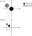
图3为本发明实施例中的基于光子复位技术的全光学超分辨显微装置的光子复位原理示意图3 is a schematic diagram of the photon reset principle of the all-optical super-resolution microscopy device based on the photon reset technology in the embodiment of the present invention
附图标记说明Description of reference numerals
1-照明系统;101-激光器;102-第一透镜组;103-微透镜阵列;2-扫描系统;201-分束镜;202-扫描振镜;203-第二透镜组;3-荧光激发收集系统;301-第一反射镜;302-第一滤光片;303-物镜;304-样品;4-去扫描系统;5-再扫描系统;501-第二反射镜;502-第三透镜组;503-第三反射镜;6-成像系统;601-第四反射镜;602-第二滤光片;603-成像透镜;604-面阵探测器;1-illumination system; 101-laser; 102-first lens group; 103-microlens array; 2-scanning system; 201-beam splitter; 202-scanning mirror; 203-second lens group; 3-fluorescence excitation 301-first mirror; 302-first filter; 303-objective lens; 304-sample; 4-descanning system; 5-rescanning system; 501-second mirror; 502-third lens group; 503-third mirror; 6-imaging system; 601-fourth mirror; 602-second filter; 603-imaging lens; 604-area detector;
具体实施方式Detailed ways
为使本发明的上述目的、特征和优点能够更为明显易懂,下面结合附图对本发明的具体实施例做详细的说明。In order to make the above objects, features and advantages of the present invention more clearly understood, the specific embodiments of the present invention will be described in detail below with reference to the accompanying drawings.
要说明的是,本发明的说明书和权利要求书及上述附图中的术语“第一”、“第二”等是用于区别类似的对象,而不必用于描述特定的顺序或先后次序。应该理解这样使用的数据在适当情况下可以互换,以便这里描述的本发明的实施例能够以除了在这里图示或描述的那些以外的顺序实施。It should be noted that the terms "first", "second" and the like in the description and claims of the present invention and the above-mentioned drawings are used to distinguish similar objects, and are not necessarily used to describe a specific sequence or sequence. It is to be understood that the data so used may be interchanged under appropriate circumstances such that the embodiments of the invention described herein can be practiced in sequences other than those illustrated or described herein.
参照图1和图2所示,本发明提出了一种基于光子复位技术的全光学超分辨显微装置包括:1 and 2, the present invention proposes an all-optical super-resolution microscopy device based on photon reset technology, including:
照明系统1,用于生成多焦点照明光束;an
扫描系统2,接受照明系统产生的多焦点照明光束,通过扫描振镜的偏转实现对样品的扫描;The
荧光激发收集系统3,通过所述扫描系统传递的多焦点照明光束对样品扫描,激发样品上的荧光信号;The fluorescence
去扫描系统4,样品反射的荧光信号通过同一光路返回,并由所述扫描振镜扫描,使得从所述照明系统入射扫描振镜的光束与所述荧光激发系统经扫描振镜出射的光束位置保持一致;Go to the
再扫描系统5,经所述去扫描系统处理后的出射光束二倍扩束,在反射镜的反射作用下再一次导向扫描振镜,实现光子复位;In the
成像系统6,接收经再扫描处理后的光束,分别对样品的不同扫描位置成像;The
参照图2,本实施例中的照明系统1包括激光器101和位于其出射光路上的透镜组102、微透镜阵列103。激光器101作为光源,用于生成激光,透镜组102用于对激光扩束,调整光束尺寸,微透镜阵列103用于接收激光,并在多个微透镜的聚光作用下生成多个平行照明光束,后续对样品304进行扫描时,可以提升扫描的效率,提升显微成像装置的成像速度。Referring to FIG. 2 , the
参照图2,本实施例中的扫描系统2位于照明系统1之后,包括分束镜201扫描振镜202、透镜组203,扫描振镜202用于接收照明系统1产生的多焦点光束,透镜组203用于调整光束尺寸,在扫描振镜202的偏转作用下多焦点激光光束依次对样品304平面进行扫描。Referring to FIG. 2 , the
参照图2,本实施例中的荧光激发收集系统3包括反射镜301、滤光片302、物镜303、样品304,多焦点照明激光光束通过物镜303导向样品304,激发样品304表面的荧光,该荧光信号经反射后由同一物镜303收集,物镜303收集到的荧光后出射,经滤光片302后导向去扫描系统4,其中,滤光片302用于滤除杂散光。2, the fluorescence
参照图2,本实施例中的去扫描系统4与所述扫描系统2包含的光学元件相同,光路行进方向相反。该系统将所述荧光激发收集系统3发射的荧光导向所述扫描振镜202,由于光束入射扫描振镜202和荧光入射扫描振镜202时,该扫描振镜202具有相同的偏转角度,故荧光光束出射的方向与激光入射扫描振镜202的方向相同,即经去扫描系统后,扫描振镜202的偏转不影响光束的传播方向,实现了去扫描的效果。Referring to FIG. 2 , the
参照图2,本实施例中的再扫描系统5包括反射镜501、透镜组502、反射镜503和扫描振镜202。经去扫描处理后的光束从所述扫描振镜202出射,导向反射镜501,在反射后的光路中设置一对透镜组502对光束进行二倍扩束。由于光束尺寸的扩大,其对应的点扩散函数的尺寸将减小一半,即将整个成像平面中成像点之间的间距缩小到原来的1/2,符合光子复位原理中将探测图像移位至激光的焦点和偏离光轴的探测点间1/2位置处的要求,实现光子复位。Referring to FIG. 2 , the
参照图3,在图像扫描显微镜中,采用面阵探测器进行成像,为了提高共焦激光扫描显微镜的分辨率,利用每个激发扫描点的不同位置信息对图像进行移位操作,更具体地说,一个发射光子的真实位置是在激发焦点和探测点之间距离的一半处。若将每一个检测到的光子重新复位到其相对应位置上,则可得到一个具有更高检测效率和分辨率的图像。在图3中,上图表示的是样品平面发射光束和激发光束的相对位置,下图表示的是图像平面发射光束和激发光束的相对位置。p表示的是激发光束的位置,s表示图像平面对应的发射光束的真实位置。通过去扫描和随后的重扫描,光束实现二倍扩束,点扩展函数的尺寸对应减小一半,两光束对应位置缩小一半,即在该图中,s=p*1/2,从而在成像过程中借助光学的方法完成了光子重新分配的内容。Referring to Fig. 3, in the image scanning microscope, an area array detector is used for imaging, in order to improve the resolution of the confocal laser scanning microscope, the image is shifted by using different position information of each excitation scanning point, more specifically , the true position of an emitted photon is half the distance between the excitation focus and the detection point. If each detected photon is reset to its corresponding position, an image with higher detection efficiency and resolution can be obtained. In Figure 3, the upper figure shows the relative position of the emission beam and excitation beam at the sample plane, and the lower figure shows the relative position of the emission beam and excitation beam at the image plane. p denotes the position of the excitation beam, and s denotes the actual position of the emitted beam corresponding to the image plane. Through de-scanning and subsequent re-scanning, the beam achieves double beam expansion, the size of the point spread function is correspondingly reduced by half, and the corresponding position of the two beams is reduced by half, that is, in this figure, s=p*1/2, so that in the imaging In the process, the content of photon redistribution is completed by means of optical methods.
参照图2,本实施例中的成像系统6包括反射镜601、发射滤光片602、成像透镜603,面阵探测器604,反射镜601改变光路方向至发射滤光片602,滤除荧光以外的杂散光后,经成像透镜603将光束聚焦到面阵探测器604上进行成像。2, the
参照图1和图2,在本技术方案中,照明系统1中的激光器101发出激光,光束经透镜组102整形后导向微透镜阵列103,生成多条平行照明光束,该光束随后被定向到分束镜201,经分束镜201偏转后定向到扫描振镜202,经扫描振镜202后的出射光束通过透镜组203实现扩展,经反射镜301反射,在滤光片302过滤作用下将光束导向物镜303并对样品304进行扫描。样品304受到激光扫描产生荧光,该荧光由同一物镜303采集,并经滤光片302滤除杂散光后沿入射路径返回,依次经过反射镜301、透镜组203、扫描振镜202后实现去扫描,去扫描后的光束在分束镜201处对荧光和激发光进行分离,分离后的荧光通过反射镜501后通过焦距比为1:2的透镜组502实现二倍扩束,扩束后的光束在反射镜503的反射后导向相同的扫描系统2上完成重扫描,利用反射镜601改变光路传播方向,并通过滤光片602滤除杂散光,最后通过成像透镜603投射到面阵探测器604上成像。1 and 2, in this technical solution, the
Claims (8)
Translated fromChinesePriority Applications (1)
| Application Number | Priority Date | Filing Date | Title |
|---|---|---|---|
| CN202010671973.3ACN111879740A (en) | 2020-07-14 | 2020-07-14 | All-optical super-resolution microscopic device based on photon reset technology |
Applications Claiming Priority (1)
| Application Number | Priority Date | Filing Date | Title |
|---|---|---|---|
| CN202010671973.3ACN111879740A (en) | 2020-07-14 | 2020-07-14 | All-optical super-resolution microscopic device based on photon reset technology |
Publications (1)
| Publication Number | Publication Date |
|---|---|
| CN111879740Atrue CN111879740A (en) | 2020-11-03 |
Family
ID=73150676
Family Applications (1)
| Application Number | Title | Priority Date | Filing Date |
|---|---|---|---|
| CN202010671973.3APendingCN111879740A (en) | 2020-07-14 | 2020-07-14 | All-optical super-resolution microscopic device based on photon reset technology |
Country Status (1)
| Country | Link |
|---|---|
| CN (1) | CN111879740A (en) |
Cited By (4)
| Publication number | Priority date | Publication date | Assignee | Title |
|---|---|---|---|---|
| CN112540067A (en)* | 2020-12-04 | 2021-03-23 | 长春理工大学 | Magnetic suspension gene biological imaging microfluidic chip switching device and imaging method thereof |
| CN112946667A (en)* | 2021-02-01 | 2021-06-11 | 哈尔滨工业大学 | Noise filtering system for improving detection signal-to-noise ratio of laser radar based on photon orbital angular momentum |
| CN116507963A (en)* | 2020-12-08 | 2023-07-28 | 深圳华大智造科技股份有限公司 | Super-resolution detection system and super-resolution detection method |
| WO2024087614A1 (en)* | 2022-10-29 | 2024-05-02 | 深圳大学 | Ratiometric fluorescence emission super-resolution imaging method |
Citations (8)
| Publication number | Priority date | Publication date | Assignee | Title |
|---|---|---|---|---|
| JP2010262176A (en)* | 2009-05-08 | 2010-11-18 | Olympus Corp | Laser scanning microscope |
| JP2015152836A (en)* | 2014-02-17 | 2015-08-24 | 横河電機株式会社 | confocal optical scanner |
| CN207946356U (en)* | 2018-03-06 | 2018-10-09 | 华南师范大学 | Multi-focus Structured Illumination Micro-Imaging Device Based on Upconversion Nanomaterials |
| CN109884051A (en)* | 2019-01-17 | 2019-06-14 | 哈尔滨工业大学 | Harmonic confocal microscopy measurement method based on image scanning |
| CN110941100A (en)* | 2019-11-29 | 2020-03-31 | 哈尔滨工业大学 | Multi-photon excitation combined multi-mode array type scanning imaging device |
| CN110967817A (en)* | 2019-11-29 | 2020-04-07 | 哈尔滨工业大学 | Image scanning microscopic imaging method and device based on double micro-lens array |
| CN210401823U (en)* | 2020-02-28 | 2020-04-24 | 哈工大机器人(中山)无人装备与人工智能研究院 | Adaptive image scanning microscopic device based on array illumination |
| CN111077078A (en)* | 2020-01-02 | 2020-04-28 | 哈工大机器人(中山)无人装备与人工智能研究院 | Two-photon microscopic imaging system combined with self-adaptive re-scanning technology |
- 2020
- 2020-07-14CNCN202010671973.3Apatent/CN111879740A/enactivePending
Patent Citations (8)
| Publication number | Priority date | Publication date | Assignee | Title |
|---|---|---|---|---|
| JP2010262176A (en)* | 2009-05-08 | 2010-11-18 | Olympus Corp | Laser scanning microscope |
| JP2015152836A (en)* | 2014-02-17 | 2015-08-24 | 横河電機株式会社 | confocal optical scanner |
| CN207946356U (en)* | 2018-03-06 | 2018-10-09 | 华南师范大学 | Multi-focus Structured Illumination Micro-Imaging Device Based on Upconversion Nanomaterials |
| CN109884051A (en)* | 2019-01-17 | 2019-06-14 | 哈尔滨工业大学 | Harmonic confocal microscopy measurement method based on image scanning |
| CN110941100A (en)* | 2019-11-29 | 2020-03-31 | 哈尔滨工业大学 | Multi-photon excitation combined multi-mode array type scanning imaging device |
| CN110967817A (en)* | 2019-11-29 | 2020-04-07 | 哈尔滨工业大学 | Image scanning microscopic imaging method and device based on double micro-lens array |
| CN111077078A (en)* | 2020-01-02 | 2020-04-28 | 哈工大机器人(中山)无人装备与人工智能研究院 | Two-photon microscopic imaging system combined with self-adaptive re-scanning technology |
| CN210401823U (en)* | 2020-02-28 | 2020-04-24 | 哈工大机器人(中山)无人装备与人工智能研究院 | Adaptive image scanning microscopic device based on array illumination |
Non-Patent Citations (6)
| Title |
|---|
| ALISTAIR CURD等: ""Construction of an instant structured illumination microscope"", 《METHODS》* |
| ANDREW G YORK等: ""Instant super-resolution imaging in live cells and embryos via analog image processing"", 《NATURE METHODS》* |
| ANDREW G YORK等: "对比文件2补充图片", 《NATURE METHODS》* |
| INGO GREGOR等: ""Image scanning microscopy"", 《CURRENT OPINION IN CHEMICAL BIOLOGY》* |
| TAKUYA AZUMA等: ""Super-resolution spinning-disk confocal microscopy using optical photon reassignment"", 《OPTICS EXPRESS》* |
| 师亚琴等: ""CCD探测型共聚焦显微成像横向分辨率优化"", 《激光与光电子学进展》* |
Cited By (4)
| Publication number | Priority date | Publication date | Assignee | Title |
|---|---|---|---|---|
| CN112540067A (en)* | 2020-12-04 | 2021-03-23 | 长春理工大学 | Magnetic suspension gene biological imaging microfluidic chip switching device and imaging method thereof |
| CN116507963A (en)* | 2020-12-08 | 2023-07-28 | 深圳华大智造科技股份有限公司 | Super-resolution detection system and super-resolution detection method |
| CN112946667A (en)* | 2021-02-01 | 2021-06-11 | 哈尔滨工业大学 | Noise filtering system for improving detection signal-to-noise ratio of laser radar based on photon orbital angular momentum |
| WO2024087614A1 (en)* | 2022-10-29 | 2024-05-02 | 深圳大学 | Ratiometric fluorescence emission super-resolution imaging method |
Similar Documents
| Publication | Publication Date | Title |
|---|---|---|
| JP6035018B2 (en) | SPIM microscope using a continuous light sheet | |
| CN111879740A (en) | All-optical super-resolution microscopic device based on photon reset technology | |
| US5381224A (en) | Scanning laser imaging system | |
| US6088097A (en) | Point-scanning luminescent microscope | |
| CN109632756B (en) | A real-time fluorescence radiation differential super-resolution microscopy method and device based on parallel spot scanning | |
| CN110023811B (en) | Optical assembly for probe light for a microscope, method for microscopic examination and microscope | |
| JP5642301B2 (en) | Scanning microscope and method for optical microscopic imaging of samples | |
| US8054542B2 (en) | Scanning laser microscope | |
| CN102841083B (en) | Method and system of laser scanning phase-microscope imaging | |
| CN103926228B (en) | A kind of laser-scanning confocal fluorescence microscopy endoscopic imaging system | |
| CN110967817A (en) | Image scanning microscopic imaging method and device based on double micro-lens array | |
| US20020141051A1 (en) | Single and multi-aperture, translationally-coupled confocal microscope | |
| CN113624666B (en) | Stream type imaging system based on dot matrix laser scanning | |
| JP6189839B2 (en) | Laser scanning microscope with illumination array | |
| CN108956561A (en) | Copolymerization coke and annular total internal reflection double mode microscopic system based on scanning galvanometer | |
| CA2973361A1 (en) | Multichannel line scan sted microscopy, method and device | |
| CN112986195B (en) | Method and device for microscopic tomography | |
| CN211785127U (en) | Optical super-resolution microscopic imaging system | |
| CN110596059A (en) | Optical super-resolution microscopic imaging system | |
| CN103954598B (en) | A kind of axial high-precision locating method based on evanescent wave illumination and device | |
| CN104967759B (en) | A kind of scanning imaging system for low light level signal | |
| CN115656130B (en) | Three-dimensional super-resolution imaging method for fluorescence emission ratio | |
| JP2001194303A (en) | Device for analyzing diffusion motion of fluorescent molecule | |
| CN114355621B (en) | A method and device for multi-point unlabeled differential super-resolution imaging | |
| CN212410444U (en) | An image scanning microscope imaging system |
Legal Events
| Date | Code | Title | Description |
|---|---|---|---|
| PB01 | Publication | ||
| PB01 | Publication | ||
| SE01 | Entry into force of request for substantive examination | ||
| SE01 | Entry into force of request for substantive examination | ||
| WD01 | Invention patent application deemed withdrawn after publication | Application publication date:20201103 | |
| WD01 | Invention patent application deemed withdrawn after publication |