CN111878292A - A self-lubricating wave energy power generation device - Google Patents
A self-lubricating wave energy power generation deviceDownload PDFInfo
- Publication number
- CN111878292A CN111878292ACN202010795524.XACN202010795524ACN111878292ACN 111878292 ACN111878292 ACN 111878292ACN 202010795524 ACN202010795524 ACN 202010795524ACN 111878292 ACN111878292 ACN 111878292A
- Authority
- CN
- China
- Prior art keywords
- rod
- lubricating
- oil
- power generation
- spring
- Prior art date
- Legal status (The legal status is an assumption and is not a legal conclusion. Google has not performed a legal analysis and makes no representation as to the accuracy of the status listed.)
- Granted
Links
- 238000010248power generationMethods0.000titleclaimsabstractdescription58
- 239000003921oilSubstances0.000claimsabstractdescription79
- 239000010687lubricating oilSubstances0.000claimsabstractdescription42
- 238000000034methodMethods0.000claimsabstractdescription7
- 230000008569processEffects0.000claimsabstractdescription6
- 230000007246mechanismEffects0.000claimsdescription32
- 230000005540biological transmissionEffects0.000claimsdescription24
- 230000009471actionEffects0.000claimsdescription21
- 238000003825pressingMethods0.000claimsdescription14
- 230000009467reductionEffects0.000claimsdescription13
- 238000007599dischargingMethods0.000claims3
- 230000033001locomotionEffects0.000abstractdescription9
- 230000000694effectsEffects0.000abstractdescription7
- 239000003595mistSubstances0.000abstractdescription7
- 238000010586diagramMethods0.000description9
- 238000005461lubricationMethods0.000description5
- 230000001050lubricating effectEffects0.000description4
- 230000002035prolonged effectEffects0.000description4
- 238000005260corrosionMethods0.000description3
- 230000007797corrosionEffects0.000description3
- 230000007774longtermEffects0.000description3
- 230000009286beneficial effectEffects0.000description2
- 230000003628erosive effectEffects0.000description2
- 230000006872improvementEffects0.000description2
- 238000006243chemical reactionMethods0.000description1
- 239000003086colorantSubstances0.000description1
- 238000009826distributionMethods0.000description1
- 230000005611electricityEffects0.000description1
- 238000005516engineering processMethods0.000description1
- 238000004519manufacturing processMethods0.000description1
- 238000012986modificationMethods0.000description1
- 230000004048modificationEffects0.000description1
Images


Classifications
- F—MECHANICAL ENGINEERING; LIGHTING; HEATING; WEAPONS; BLASTING
- F03—MACHINES OR ENGINES FOR LIQUIDS; WIND, SPRING, OR WEIGHT MOTORS; PRODUCING MECHANICAL POWER OR A REACTIVE PROPULSIVE THRUST, NOT OTHERWISE PROVIDED FOR
- F03B—MACHINES OR ENGINES FOR LIQUIDS
- F03B13/00—Adaptations of machines or engines for special use; Combinations of machines or engines with driving or driven apparatus; Power stations or aggregates
- F03B13/12—Adaptations of machines or engines for special use; Combinations of machines or engines with driving or driven apparatus; Power stations or aggregates characterised by using wave or tide energy
- F03B13/14—Adaptations of machines or engines for special use; Combinations of machines or engines with driving or driven apparatus; Power stations or aggregates characterised by using wave or tide energy using wave energy
- F03B13/16—Adaptations of machines or engines for special use; Combinations of machines or engines with driving or driven apparatus; Power stations or aggregates characterised by using wave or tide energy using wave energy using the relative movement between a wave-operated member, i.e. a "wom" and another member, i.e. a reaction member or "rem"
- F03B13/18—Adaptations of machines or engines for special use; Combinations of machines or engines with driving or driven apparatus; Power stations or aggregates characterised by using wave or tide energy using wave energy using the relative movement between a wave-operated member, i.e. a "wom" and another member, i.e. a reaction member or "rem" where the other member, i.e. rem is fixed, at least at one point, with respect to the sea bed or shore
- F03B13/1845—Adaptations of machines or engines for special use; Combinations of machines or engines with driving or driven apparatus; Power stations or aggregates characterised by using wave or tide energy using wave energy using the relative movement between a wave-operated member, i.e. a "wom" and another member, i.e. a reaction member or "rem" where the other member, i.e. rem is fixed, at least at one point, with respect to the sea bed or shore and the wom slides relative to the rem
- F—MECHANICAL ENGINEERING; LIGHTING; HEATING; WEAPONS; BLASTING
- F16—ENGINEERING ELEMENTS AND UNITS; GENERAL MEASURES FOR PRODUCING AND MAINTAINING EFFECTIVE FUNCTIONING OF MACHINES OR INSTALLATIONS; THERMAL INSULATION IN GENERAL
- F16N—LUBRICATING
- F16N11/00—Arrangements for supplying grease from a stationary reservoir or the equivalent in or on the machine or member to be lubricated; Grease cups
- F—MECHANICAL ENGINEERING; LIGHTING; HEATING; WEAPONS; BLASTING
- F16—ENGINEERING ELEMENTS AND UNITS; GENERAL MEASURES FOR PRODUCING AND MAINTAINING EFFECTIVE FUNCTIONING OF MACHINES OR INSTALLATIONS; THERMAL INSULATION IN GENERAL
- F16N—LUBRICATING
- F16N13/00—Lubricating-pumps
- F16N13/02—Lubricating-pumps with reciprocating piston
- F16N13/06—Actuation of lubricating-pumps
- F16N13/10—Actuation of lubricating-pumps with mechanical drive
- F16N13/12—Actuation of lubricating-pumps with mechanical drive with ratchet
- H—ELECTRICITY
- H02—GENERATION; CONVERSION OR DISTRIBUTION OF ELECTRIC POWER
- H02K—DYNAMO-ELECTRIC MACHINES
- H02K35/00—Generators with reciprocating, oscillating or vibrating coil system, magnet, armature or other part of the magnetic circuit
- H02K35/04—Generators with reciprocating, oscillating or vibrating coil system, magnet, armature or other part of the magnetic circuit with moving coil systems and stationary magnets
- Y—GENERAL TAGGING OF NEW TECHNOLOGICAL DEVELOPMENTS; GENERAL TAGGING OF CROSS-SECTIONAL TECHNOLOGIES SPANNING OVER SEVERAL SECTIONS OF THE IPC; TECHNICAL SUBJECTS COVERED BY FORMER USPC CROSS-REFERENCE ART COLLECTIONS [XRACs] AND DIGESTS
- Y02—TECHNOLOGIES OR APPLICATIONS FOR MITIGATION OR ADAPTATION AGAINST CLIMATE CHANGE
- Y02E—REDUCTION OF GREENHOUSE GAS [GHG] EMISSIONS, RELATED TO ENERGY GENERATION, TRANSMISSION OR DISTRIBUTION
- Y02E10/00—Energy generation through renewable energy sources
- Y02E10/30—Energy from the sea, e.g. using wave energy or salinity gradient
Landscapes
- Engineering & Computer Science (AREA)
- General Engineering & Computer Science (AREA)
- Mechanical Engineering (AREA)
- Chemical & Material Sciences (AREA)
- Combustion & Propulsion (AREA)
- Power Engineering (AREA)
- Other Liquid Machine Or Engine Such As Wave Power Use (AREA)
Abstract
Translated fromChinese
Description
Translated fromChinese技术领域technical field
本发明涉及海上发电技术领域,具体涉及一种自润滑波浪能发电装置。The invention relates to the technical field of offshore power generation, in particular to a self-lubricating wave energy power generation device.
背景技术Background technique
海洋面积约占地球表面积的71%,开发海洋资源和发展海洋经济,迫切需要解决海岛、海上平台的电力短缺问题。为了科学经济地解决好该问题,必须因地制宜,充分开发取之不尽用之不竭的海洋能。波浪能源是巨大的能源之一,其能量密度高于太阳能和风能等一些可再生资源,虽然波浪能是海洋能源中能量最不稳定的一种能源,但是其分布范围广且易于大规模开采利用,如果能高效可靠地利用波浪能进行发电,就能有效解决上述电力短缺问题。近年来,波浪能发电技术发展迅速,出现了各式各样的波浪能发电装置,波浪能发电装置是将波浪能转换为机械能,机械能转化为电能的电力设备,但是现有的部分发电装置采用直线电机进行电力转换,在波浪的作用下,发电装置中的振子上下振动,线圈切割磁力线,直线发电机产生电流,进行发电,其结构复杂、体积大、拆装和更换都不方便, 并且由于这种装置是全密封的,且放入海里工作,导杆与振子之间摩擦副过多,在使用过程中,摩擦副会消耗大量的能量,而这些能量都是由波浪能提供的,导致波浪能产生的能量大多都被摩擦副消耗掉,实际对波浪能的利用率很低,并且摩擦副运动时会产生大量的热量,会影响装置内部其它零件的使用寿命。The ocean area accounts for about 71% of the earth's surface. To develop marine resources and develop the marine economy, it is urgent to solve the problem of power shortages on islands and offshore platforms. In order to solve this problem scientifically and economically, it is necessary to fully develop the inexhaustible ocean energy according to local conditions. Wave energy is one of the huge energy sources, and its energy density is higher than some renewable resources such as solar energy and wind energy. Although wave energy is the most unstable energy source in ocean energy, it has a wide distribution range and is easy to be exploited and utilized on a large scale. , if the wave energy can be efficiently and reliably used for power generation, the above-mentioned power shortage problem can be effectively solved. In recent years, wave energy power generation technology has developed rapidly, and various wave energy power generation devices have appeared. Wave energy power generation devices are electrical equipment that converts wave energy into mechanical energy and mechanical energy into electrical energy. The linear motor performs power conversion. Under the action of the wave, the vibrator in the power generation device vibrates up and down, the coil cuts the magnetic field line, and the linear generator generates current to generate electricity. Its structure is complex, the volume is large, and the disassembly and replacement are inconvenient. This kind of device is fully sealed, and it is put into the sea to work. There are too many friction pairs between the guide rod and the vibrator. During use, the friction pairs will consume a lot of energy, and these energy are provided by wave energy, resulting in Most of the energy generated by the wave energy is consumed by the friction pair, and the actual utilization rate of the wave energy is very low, and a large amount of heat is generated when the friction pair moves, which will affect the service life of other parts inside the device.
发明内容SUMMARY OF THE INVENTION
为了解决以上问题,本发明提供一种自润滑波浪能发电装置,结构相对简单且紧凑,且所有部件均密封在外筒内部,不必担心长时间海上工作的腐蚀失效等问题,设计了自润滑装置, 通过液压泵将下油池箱体中的润滑油打入到上油池箱体中,润滑油从上油池流入到导杆表面,对导杆进行润滑,在此发电装置的工作过程中,可以连续地对导杆进行润滑,降低振子与导杆的摩擦系数,延长了此装置的寿命,使发电效率得以提高,无需另外寻找动力源,直接利用振子的上下运动获取动力,按压液压泵,给导杆加入润滑油,解决该装置的润滑问题,本发明还设计了和自润滑装置配套使用的降频机构,通过此机构可以使加润滑油频率保持在合理数值范围内,使润滑效果达到最佳状态。In order to solve the above problems, the present invention provides a self-lubricating wave energy power generation device, which has a relatively simple and compact structure, and all components are sealed inside the outer cylinder, so there is no need to worry about the corrosion failure of long-term offshore work, and a self-lubricating device is designed. The lubricating oil in the lower oil pool box is driven into the upper oil pool box by the hydraulic pump, and the lubricating oil flows from the upper oil pool to the surface of the guide rod to lubricate the guide rod. The guide rod can be lubricated continuously, reducing the friction coefficient between the vibrator and the guide rod, prolonging the life of the device, and improving the power generation efficiency. Adding lubricating oil to the guide rod solves the problem of lubricating the device. The invention also designs a frequency reduction mechanism that is matched with the self-lubricating device. Through this mechanism, the frequency of adding lubricating oil can be kept within a reasonable range, so that the lubricating effect can reach Best state.
为达此目的,本发明提供的一种自润滑波浪能发电装置,包括电控柜、导杆、振子、弹簧板、缓冲弹簧、底盘、发电机定子架、顶盘、外筒、锚链和发电机线圈,所述锚链一端链接于所述自润滑波浪能发电装置的外筒上,另一端固定于海底,防止所述自润滑波浪能发电装置随波飘走,所述外筒将所有发电装置的部件包裹在内,所述发电装置还包括自润滑装置,所述自润滑装置包括上油池箱体、出油管、液压泵、下油池箱体、手柄拉动机构、支撑架、凸轮、棘轮带轮组、棘爪和制动棘爪,所述电控柜可拆卸式安装于所述顶盘的上方,所述上油池箱体固定安装于所述顶盘下方,所述下油池箱体固定安装于所述底盘上方,所述导杆通过导套安装在所述上油池箱体和所述下油池箱体之间,所述缓冲弹簧套在所述导杆上并用销固定在所述下油池箱体上表面,所述弹簧板空套在所述导杆上,并可沿所述导杆上下移动,所述振子位于所述缓冲弹簧上方,通过直线轴承穿过所述导杆,并可以沿着所述导杆上下移动,直线发电机的发电机线圈卡入在所述振子里,所述发电机定子架里固定有永磁体,所述支撑架、所述手柄拉动机构和所述液压泵依次排列安装于所述下油池箱体上表面,所述凸轮包括外凸轮、轴孔和内凸轮,所述外凸轮和所述内凸轮之间形成有偏心凸轮槽,所述手柄拉动机构包括手柄滑杆、圆柱导销、按压手柄、滑杆弹簧、支撑台和平带,所述棘轮带轮组包括带轮、拨杆、滚子、滑槽、滑块杆、传动轴和棘轮,所述手柄拉动机构通过所述支撑台安装在所述下油池箱体上表面,所述传动轴穿过所述凸轮上的轴孔后两端固定于所述支撑架上开设的通孔内,所述平带一端固定在所述带轮正上方,另一端逆时针绕过所述带轮并在所述带轮下方展开固定在所述手柄滑杆上,所述手柄滑杆可在所述支撑台上的导轨上自由来回移动,所述滑杆弹簧卡在所述支撑台左端和所述手柄滑杆之间,所述手柄滑杆右端装有所述圆柱导销,所述圆柱导销穿入所述液压泵的所述按压手柄的一字槽中,并可沿一字槽来回移动,所述拨杆通过键固定在所述传动轴上,所述传动轴转动带动拨杆转动,所述带轮空套在传动轴上,并利用轴肩和弹簧卡圈进行轴向定位,所述滑槽位于所述带轮上,滑块杆一端嵌入在所述滑槽内并可在所述滑槽内自由移动,另一端安装有滚子,所述滚子卡在所述偏心凸轮槽中,所述滚子的初始位置与所述传动轴的向径最小,所述液压泵穿过下油池箱体固定在所述底盘上,所述液压泵的出油管一端与所述液压泵相连,另一端穿过所述上油池箱体的侧壁进入到所述上油池箱体里,工作时,当振子向下运动时,按压液压泵, 将润滑油从下油池箱体打入到上油池箱体内,上油池箱体内的润滑油通过导套与所述导杆之间的间隙缓慢流到所述导杆表面,润滑油顺着导杆流入到所述下油池箱体内,润滑油如此循环,从而实现发电装置自润滑的过程。本发明中设置的自润滑装置可以连续地对导杆进行润滑,降低振子与导杆的摩擦系数,使发电效率得以提高,延长了整个波浪能发电装置的寿命。To achieve this purpose, the present invention provides a self-lubricating wave energy power generation device, comprising an electric control cabinet, a guide rod, a vibrator, a spring plate, a buffer spring, a chassis, a generator stator frame, a top plate, an outer cylinder, an anchor chain and The generator coil, one end of the anchor chain is linked to the outer cylinder of the self-lubricating wave energy power generation device, and the other end is fixed to the seabed, so as to prevent the self-lubricating wave energy power generation device from drifting away with the waves, and the outer cylinder connects all the The components of the power generation device are wrapped, and the power generation device also includes a self-lubricating device, which includes an upper oil tank box, an oil outlet pipe, a hydraulic pump, a lower oil tank box, a handle pulling mechanism, a support frame, a cam , a ratchet pulley set, a pawl and a braking pawl, the electric control cabinet is detachably installed above the top plate, the upper oil tank box is fixedly installed under the top plate, and the lower The oil pool box is fixedly installed above the chassis, the guide rod is installed between the upper oil pool box and the lower oil pool box through a guide sleeve, and the buffer spring is sleeved on the guide rod And fixed on the upper surface of the lower oil tank box with a pin, the spring plate is empty on the guide rod, and can move up and down along the guide rod, the vibrator is located above the buffer spring, through the linear bearing Through the guide rod, and can move up and down along the guide rod, the generator coil of the linear generator is stuck in the vibrator, the permanent magnet is fixed in the generator stator frame, the support frame, The handle pulling mechanism and the hydraulic pump are arranged and installed on the upper surface of the lower oil pool box in sequence, the cam includes an outer cam, a shaft hole and an inner cam, and a cam is formed between the outer cam and the inner cam. Eccentric cam groove, the handle pulling mechanism includes a handle sliding rod, a cylindrical guide pin, a pressing handle, a sliding rod spring, a support platform and a flat belt, and the ratchet pulley set includes a pulley, a lever, a roller, a chute, a sliding A block rod, a transmission shaft and a ratchet wheel, the handle pulling mechanism is installed on the upper surface of the lower oil sump box through the support table, and the transmission shaft passes through the shaft hole on the cam and is fixed at both ends of the In the through hole opened on the support frame, one end of the flat belt is fixed directly above the pulley, and the other end goes around the pulley counterclockwise and is unfolded and fixed on the handle slide bar below the pulley, The handle sliding rod can move back and forth freely on the guide rail on the support table, the sliding rod spring is clamped between the left end of the supporting table and the handle sliding rod, and the right end of the handle sliding rod is equipped with the Cylindrical guide pin, the cylindrical guide pin penetrates into the slot of the pressing handle of the hydraulic pump, and can move back and forth along the slot, and the lever is fixed on the transmission shaft through a key, so The rotation of the transmission shaft drives the lever to rotate, the pulley is idle on the transmission shaft, and is positioned axially by the shaft shoulder and the spring clip, the chute is located on the pulley, and one end of the slider rod is embedded in the pulley. The sliding groove can move freely in the sliding groove, and the other end is equipped with a roller, the roller is stuck in the eccentric cam groove, and the initial position of the roller is the same as the radial direction of the transmission shaft. The minimum, the hydraulic pump is fixed on the chassis through the lower oil tank box, one end of the oil outlet pipe of the hydraulic pump is connected to the hydraulic pump, and the other end passes through the side wall of the upper oil tank box to enter the chassis. When the vibrator moves downward, press the hydraulic pump to drive the lubricating oil from the lower oil pool box into the upper oil pool box, and the lubrication in the upper oil pool box The oil flows slowly to the surface of the guide rod through the gap between the guide sleeve and the guide rod, and the lubricating oil flows into the lower oil pool box along the guide rod. process. The self-lubricating device provided in the present invention can continuously lubricate the guide rod, reduce the friction coefficient between the vibrator and the guide rod, improve the power generation efficiency, and prolong the life of the entire wave energy power generation device.
由于在装置外部设置了外筒,可以有效保护其内的发电机、控制器等元器件,免受雨水、海气的侵蚀,延长使用寿命。Since the outer cylinder is set outside the device, the generator, controller and other components in it can be effectively protected from the erosion of rain and sea air, and the service life can be prolonged.
所述发电装置还包括和所述自润滑装置配套使用的降频机构,所述降频机构是由棘爪、棘轮和制动棘爪组成的棘轮间歇机构,所述棘爪固定在所述弹簧板下表面,所述棘轮通过键固定在所述传动轴上,所述带轮在所述拨杆和所述棘轮之间,所述棘轮转动带动所述传动轴同步转动,当振子向下运动时,按压弹簧板,所述弹簧板克服弹簧力继续向下运动,安装在弹簧板下端的棘爪推动棘轮顺时针转动一定角度,拨杆也跟着同步转动,带轮在滑杆弹簧的作用下保持不动,当振子向上运动时,弹簧板在弹簧力的作用下上移,棘爪跟着上移,此时棘轮在制动棘爪的作用下不转动,振子不断地做上下移动,棘轮做间歇顺时针转动,当拨杆转动到与带轮上的滑块杆接触时,拨杆推动滑块杆运动,滑块杆推动带轮,使带轮克服滑杆弹簧力顺时针转动,平带在带轮的转动下向左移动,拉动手柄滑杆克服滑杆弹簧向左移动,通过圆柱导销,顺时针转动液压泵手柄,使液压泵加压一次,由于滑块杆头部滚子卡在偏心凸轮槽内,当带轮顺时针转动时,由于偏心凸轮槽形状的限制,滑块杆在偏心凸轮槽的作用下不断向远离轴心的位置移动,当滑块杆离凸轮轴向径长度大于拨杆长度时,滑块杆与拨杆脱离,此时带轮在滑杆弹簧的作用下迅速逆时针转动复位,带轮上的滑块杆在偏心凸轮槽的作用下向靠近轴心方向移动复位,即滑块杆离凸轮轴的向径重新恢复到最小值;同时手柄滑杆在滑杆弹簧的作用下向右移动复位,通过圆柱导销逆时针转动按压手柄使按压手柄逆时针转动复位,等待下一次加压,如此反复循环,即可定量的给导柱提供适量的润滑油。由于振子运动时频率较高,直接利用此频率对液压泵加压会导致加入的润滑油量过多,在滑动摩擦下产生大量油雾影响发电效果,为了降低加油频率,为了解决上述问题,所以本发明就设计了上述和自润滑装置配套使用的降频机构,通过棘轮、带轮、凸轮及拨杆等构件大大降低了液压泵加油的频率,使整个发电装置既不会因为缺少润滑油导致摩擦系数增大,使振子运动发生干涩咬死的现象,又不会因为润滑油过多产生油雾,影响发电效果,可以使得加润滑油频率一直保持在合理数值范围内,使润滑效果达到最佳状态。并且本发明的降频机构,直接利用了振子的上下运动获取动力,按压液压泵,给导杆加入润滑油,解决该装置的润滑问题,无需另外寻找动力源,使得整个机构结构紧凑,简单易制造。The power generation device also includes a frequency reduction mechanism used in conjunction with the self-lubricating device. The frequency reduction mechanism is a ratchet intermittent mechanism composed of a pawl, a ratchet and a braking pawl, and the pawl is fixed on the spring. The lower surface of the plate, the ratchet is fixed on the transmission shaft by a key, the pulley is between the lever and the ratchet, the rotation of the ratchet drives the transmission shaft to rotate synchronously, when the vibrator moves downward When pressing the spring plate, the spring plate overcomes the spring force and continues to move downward, the pawl installed at the lower end of the spring plate pushes the ratchet wheel to rotate clockwise by a certain angle, the lever also rotates synchronously, and the pulley is under the action of the slide bar spring Keep still, when the vibrator moves upward, the spring plate moves up under the action of the spring force, and the pawl moves up. At this time, the ratchet does not rotate under the action of the braking pawl, the vibrator moves up and down continuously, and the ratchet does. Rotate clockwise intermittently, when the lever rotates to contact with the slider rod on the pulley, the lever pushes the slider rod to move, the slider rod pushes the pulley, so that the pulley rotates clockwise against the spring force of the slider, and the flat belt Move to the left under the rotation of the pulley, pull the handle slide bar to overcome the slide bar spring and move to the left, through the cylindrical guide pin, turn the hydraulic pump handle clockwise to pressurize the hydraulic pump once. In the eccentric cam groove, when the pulley rotates clockwise, due to the limitation of the shape of the eccentric cam groove, the slider rod continuously moves away from the axis under the action of the eccentric cam groove. When the length is greater than the length of the lever, the slider rod is disengaged from the lever. At this time, the pulley quickly rotates counterclockwise to reset under the action of the slider spring, and the slider rod on the pulley moves closer to the axis under the action of the eccentric cam groove. The direction moves to reset, that is, the diameter of the slider rod from the camshaft returns to the minimum value; at the same time, the handle slider moves to the right under the action of the slider spring to reset, and the cylindrical guide pin rotates the pressing handle counterclockwise to make the pressing handle counterclockwise. Rotate to reset, wait for the next pressurization, and repeat this cycle to provide the right amount of lubricating oil to the guide post quantitatively. Due to the high frequency when the vibrator moves, directly using this frequency to pressurize the hydraulic pump will lead to excessive amount of lubricating oil added, and a large amount of oil mist will be generated under the sliding friction, which will affect the power generation effect. In order to reduce the frequency of refueling and solve the above problems, so The present invention designs the frequency reduction mechanism used in conjunction with the self-lubricating device. The ratchet, pulley, cam, lever and other components greatly reduce the refueling frequency of the hydraulic pump, so that the entire power generation device will not be caused by lack of lubricating oil. The increase of the friction coefficient makes the vibrator motion dry and bites, and the oil mist will not be generated due to too much lubricating oil, which will affect the power generation effect. in good condition. In addition, the frequency reduction mechanism of the present invention directly utilizes the up and down motion of the vibrator to obtain power, presses the hydraulic pump, and adds lubricating oil to the guide rod, so as to solve the lubrication problem of the device, without the need to find another power source, making the entire mechanism compact, simple and easy. manufacture.
作为本发明的一种改进,所述外筒表面喷涂有起警示识别作用的警示颜色。优选红色,可以起到警示识别作用。As an improvement of the present invention, the surface of the outer cylinder is sprayed with a warning color for warning and identification. Red is preferred, which can play a warning and identification role.
作为本发明的一种改进,所述导杆数量为2~4个。3个导柱使得整个装置更加稳定。As an improvement of the present invention, the number of the guide rods is 2-4. 3 guide posts make the whole device more stable.
本发明相对现有技术所具有的有益效果是:本发明的一种自润滑波浪能发电装置,结构相对简单且紧凑,且所有部件均密封在外筒内部,不必担心长时间海上工作的腐蚀失效等问题,设计了自润滑装置, 通过液压泵将下油池箱体中的润滑油打入到上油池箱体中,润滑油从上油池流入到导杆表面,对导杆进行润滑,在此发电装置的工作过程中,可以连续地对导杆进行润滑,降低振子与导杆的摩擦系数,使发电效率得以提高, 延长了此装置的寿命,本发明设计的和自润滑装置配套使用的降频机构,通过棘轮、带轮、凸轮及拨杆等构件大大降低了液压泵加油的频率,使整个发电装置既不会因为缺少润滑油导致摩擦系数增大,使振子运动发生干涩咬死的现象,又不会因为润滑油过多产生油雾,影响发电效果,可以使得加润滑油频率一直保持在合理数值范围内,使润滑效果达到最佳状态,本发明中设计的降频机构,直接利用振子的上下运动获取动力,按压液压泵,给导杆加入润滑油,解决该装置的润滑问题,无需另外寻找动力源,具有较强的实用性和较好的应用前景。The beneficial effects of the present invention relative to the prior art are: the self-lubricating wave energy power generation device of the present invention has a relatively simple and compact structure, and all components are sealed inside the outer cylinder, so there is no need to worry about corrosion failure in long-term offshore work, etc. To solve the problem, a self-lubricating device is designed. The lubricating oil in the lower oil pool box is driven into the upper oil pool box by the hydraulic pump, and the lubricating oil flows from the upper oil pool to the surface of the guide rod to lubricate the guide rod. During the working process of the power generation device, the guide rod can be lubricated continuously, reducing the friction coefficient between the vibrator and the guide rod, so that the power generation efficiency can be improved, and the life of the device can be prolonged. The frequency reduction mechanism greatly reduces the refueling frequency of the hydraulic pump through ratchets, pulleys, cams, levers and other components, so that the entire power generation device will not increase the friction coefficient due to lack of lubricating oil, and cause the vibrator movement to dry and bite. It will not produce oil mist due to too much lubricating oil, which will affect the power generation effect, so that the frequency of adding lubricating oil can always be kept within a reasonable value range, so that the lubricating effect can reach the best state. The frequency reduction mechanism designed in the present invention directly The up and down motion of the vibrator is used to obtain power, the hydraulic pump is pressed, and lubricating oil is added to the guide rod to solve the lubrication problem of the device, and there is no need to find another power source, which has strong practicability and good application prospects.
附图说明Description of drawings
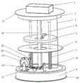
图1 本发明的自润滑波浪能发电装置的整体结构正面示意图(去除外筒);Figure 1 is a schematic front view of the overall structure of the self-lubricating wave energy power generation device of the present invention (with the outer cylinder removed);
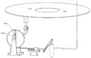
图2 为图1加上外筒后的整体结构示意图;Figure 2 is a schematic diagram of the overall structure of Figure 1 after adding the outer cylinder;
图3 为本发明的自润滑波浪能发电装置的整体结构反面示意图(去除外筒);Figure 3 is a schematic diagram of the reverse side of the overall structure of the self-lubricating wave energy power generation device of the present invention (with the outer cylinder removed);
图4 为图1中的凸轮的结构示意图;Fig. 4 is the structural representation of the cam in Fig. 1;
图5 为图1中的棘轮带轮组的结构示意图;Figure 5 is a schematic structural diagram of the ratchet pulley set in Figure 1;
图6 为手柄拉动机构的结构示意图;Figure 6 is a schematic diagram of the structure of the handle pulling mechanism;
图7为棘轮拨杆转动状态图(去除凸轮,带轮不动);Figure 7 is a diagram of the rotation state of the ratchet lever (the cam is removed, and the pulley does not move);
图8 为拨杆与滑块杆刚接触时状态图(去除凸轮);Figure 8 is the state diagram when the lever and the slider rod are just in contact (the cam is removed);
图9 为拨杆与滑块杆即将分离时状态图(滑块杆离轴心距离最大时状态图);Figure 9 is the state diagram when the lever and the slider rod are about to be separated (the state diagram when the slider rod is at the largest distance from the axis);
图10 为滑块杆复位时状态图;Figure 10 is the state diagram when the slider rod is reset;
1、电控柜;2、上油池箱体;3、出油管;4、导杆;5、振子;6、弹簧板;7、缓冲弹簧;8、液压泵1. Electric control cabinet; 2. Upper oil tank body; 3. Oil outlet pipe; 4. Guide rod; 5. Vibrator; 6. Spring plate; 7. Buffer spring; 8. Hydraulic pump
9、下油池箱体;10、底盘;11、手柄拉动机构;11-1、手柄滑杆;11-2、圆柱导销;11-3、按压手柄;11-4、滑杆弹簧;11-5、支撑台;11-6、平带;12、支撑架;13、凸轮;13-1、外凸轮;13-2、轴孔;13-3、偏心凸轮槽;13-4、内凸轮;14、棘轮带轮组;14-1、带轮;14-2、拨杆;14-3、滚子;14-4、滑槽;14-5、滑块杆;14-6、传动轴;14-7、棘轮;15、棘爪;16、发电机定子架;17、顶盘;18、外筒;19、锚链;20、制动棘爪;21、发电机线圈。9. Lower oil tank box; 10. Chassis; 11. Handle pulling mechanism; 11-1, handle sliding rod; 11-2, cylindrical guide pin; 11-3, pressing handle; 11-4, sliding rod spring; 11 -5, support table; 11-6, flat belt; 12, support frame; 13, cam; 13-1, outer cam; 13-2, shaft hole; 13-3, eccentric cam groove; 13-4, inner cam ;14, ratchet pulley group; 14-1, pulley; 14-2, lever; 14-3, roller; 14-4, chute; 14-5, slider rod; 14-6, drive shaft ;14-7, ratchet; 15, pawl; 16, generator stator frame; 17, top plate; 18, outer cylinder; 19, anchor chain; 20, brake pawl; 21, generator coil.
具体实施方式Detailed ways
下面将结合本发明实施例中的附图,对本发明实施例中的技术方案进行清楚、完整地描述,显然,所描述的实施例仅仅是本发明一部分实施例,而不是全部的实施例。基于本发明中的实施例,本领域普通技术人员在没有作出创造性劳动前提下所获得的所有其它实施例,都属于本发明保护的范围。The technical solutions in the embodiments of the present invention will be clearly and completely described below with reference to the accompanying drawings in the embodiments of the present invention. Obviously, the described embodiments are only a part of the embodiments of the present invention, but not all of the embodiments. Based on the embodiments of the present invention, all other embodiments obtained by those of ordinary skill in the art without creative efforts shall fall within the protection scope of the present invention.
如图1-图3所示,本发明提供的一种自润滑波浪能发电装置,包括电控柜1、导杆4、振子5、弹簧板6、缓冲弹簧7、底盘10、发电机定子架16、顶盘17、外筒18、锚链19和发电机线圈21,所述锚链19一端链接于所述自润滑波浪能发电装置的外筒18上,另一端固定于海底,防止所述自润滑波浪能发电装置随波飘走,所述外筒18将所有发电装置的部件包裹在内,所述发电装置还包括自润滑装置,所述自润滑装置包括上油池箱体2、出油管3、液压泵8、下油池箱体9、手柄拉动机构11、支撑架12、凸轮13、棘轮带轮组14、棘爪15和制动棘爪20,所述电控柜1可拆卸式安装于所述顶盘17的上方,所述上油池箱体2固定安装于所述顶盘17下方,所述下油池箱体9固定安装于所述底盘10上方,所述导杆4通过导套安装在所述上油池箱体2和所述下油池箱体9之间,所述缓冲弹簧7套在所述导杆4上并用销固定在所述下油池箱体9上表面,所述弹簧板6空套在所述导杆4上,并可沿所述导杆4上下移动,所述振子5位于所述缓冲弹簧7上方,通过直线轴承穿过所述导杆4,并可以沿着所述导杆4上下移动,直线发电机的发电机线圈21卡入在所述振子5里,所述发电机定子架16里固定有永磁体,所述支撑架12、所述手柄拉动机构11和所述液压泵8依次排列安装于所述下油池箱体9上表面,如图4所示,所述凸轮13包括外凸轮13-1、轴孔13-2和内凸轮13-4,所述外凸轮13-1和所述内凸轮13-4之间形成有偏心凸轮槽13-3,如图5所示,所述棘轮带轮组14包括带轮14-1、拨杆14-2、滚子14-3、滑槽14-4、滑块杆14-5、传动轴14-6和棘轮14-7,如图6所述手柄拉动机构11包括手柄滑杆11-1、圆柱导销11-2、按压手柄11-3、滑杆弹簧11-4、支撑台11-5和平带11-6,所述手柄拉动机构11通过所述支撑台11-5安装在所述下油池箱体9上表面,所述传动轴14-6穿过所述凸轮13上的轴孔13-2后两端固定于所述支撑架12上开设的通孔内,所述平带11-6一端固定在所述带轮14-1正上方,另一端逆时针绕过所述带轮14-1并在所述带轮14-1下方展开固定在所述手柄滑杆11-1上,所述手柄滑杆11-1可在所述支撑台11-5上的导轨上自由来回移动,所述滑杆弹簧11-4卡在所述支撑台11-5左端和所述手柄滑杆11-1之间,所述手柄滑杆11-1右端装有所述圆柱导销11-2,所述圆柱导销11-2穿入所述液压泵8的所述按压手柄11-3的一字槽中,并可沿一字槽来回移动,所述拨杆14-2通过键固定在所述传动轴14-6上,所述传动轴14-6转动带动拨杆14-2转动,所述带轮14-1空套在传动轴14-6上,并利用轴肩和弹簧卡圈进行轴向定位,所述滑槽14-4位于所述带轮14-1上,滑块杆14-5一端嵌入在所述滑槽14-4内并可在所述滑槽14-4内自由移动,另一端安装有滚子14-3,所述滚子14-3卡在所述偏心凸轮槽13-3中,所述滚子14-3的初始位置与所述传动轴14-6的向径最小,所述液压泵8穿过下油池箱体9固定在所述底盘10上,所述液压泵8的出油管3一端与所述液压泵8相连,另一端穿过所述上油池箱体2的侧壁进入到所述上油池箱体2里,工作时,当振子5向下运动时,按压液压泵8, 将润滑油从下油池箱体9打入到上油池箱体2内,上油池箱体2内的润滑油通过导套与所述导杆4之间的间隙缓慢流到所述导杆4表面,润滑油顺着导杆流入到所述下油池箱体9内,润滑油如此循环,从而实现发电装置自润滑的过程。As shown in Figures 1-3, a self-lubricating wave energy power generation device provided by the present invention includes an electric control cabinet 1, a guide rod 4, a vibrator 5, a spring plate 6, a buffer spring 7, a
由于在装置外部设置了外筒,可以有效保护其内的发电机、控制器等元器件,免受雨水、海气的侵蚀,延长使用寿命。Since the outer cylinder is set outside the device, the generator, controller and other components in it can be effectively protected from the erosion of rain and sea air, and the service life can be prolonged.
所述发电装置还包括和所述自润滑装置配套使用的降频机构,所述降频机构是由棘爪15、棘轮14-7和制动棘爪20组成的棘轮间歇机构,所述棘爪15固定在所述弹簧板6下表面,所述棘轮14-7通过键固定在所述传动轴14-6上,所述带轮14-1在所述拨杆14-2和所述棘轮14-7之间,所述棘轮14-7转动带动所述传动轴14-6同步转动,如图7所示,当振子5向下运动时,按压弹簧板6,所述弹簧板6克服弹簧力继续向下运动,安装在弹簧板6下端的棘爪15推动棘轮14-7顺时针转动一定角度,拨杆14-2也跟着同步转动,带轮14-1在滑杆弹簧11-4的作用下保持不动,当振子5向上运动时,弹簧板6在弹簧力的作用下上移,棘爪15跟着上移,此时棘轮14-7在制动棘爪20的作用下不转动,振子5不断地做上下移动,棘轮14-7做间歇顺时针转动,当拨杆14-2转动到与带轮14-1上的滑块杆14-5接触时,如图8所示,拨杆14-2推动滑块杆14-5运动,滑块杆14-5推动带轮14-1,使带轮14-1克服滑杆弹簧11-4力顺时针转动,平带11-6在带轮14-1的转动下向左移动,拉动手柄滑杆11-1克服滑杆弹簧11-4向左移动,通过圆柱导销11-2,顺时针转动液压泵8手柄,使液压泵8加压一次,由于滑块杆14-5头部滚子14-3卡在偏心凸轮槽13-3内,当带轮14-1顺时针转动时,由于偏心凸轮槽13-3形状的限制,滑块杆14-5在偏心凸轮槽13-3的作用下不断向远离轴心的位置移动,即滑块杆离凸轮轴的向径不断增加如图9所示,当滑块杆14-5离凸轮13轴向径长度大于拨杆14-2长度时,滑块杆14-5与拨杆14-2脱离,此时带轮14-1在滑杆弹簧11-4的作用下迅速逆时针转动复位,带轮14-1上的滑块杆14-5在偏心凸轮槽13-3的作用下向靠近轴心方向移动复位,即滑块杆14-5离凸轮轴的向径重新恢复到最小值;同时手柄滑杆11-1在滑杆弹簧11-4的作用下向右移动复位,通过圆柱导销11-2逆时针转动按压手柄11-3使按压手柄11-3逆时针转动复位(如图10所示),等待下一次加压,如此反复循环,即可定量的给导柱提供适量的润滑油。由于振子运动时频率较高,直接利用此频率对液压泵加压会导致加入的润滑油量过多,在滑动摩擦下产生大量油雾影响发电效果,为了降低加油频率,本发明就设计了上述和自润滑装置配套使用的降频机构,通过棘轮、带轮、凸轮及拨杆等构件大大降低了液压泵加油的频率,使整个发电装置既不会因为缺少润滑油导致摩擦系数增大,使振子运动发生干涩咬死的现象,又不会因为润滑油过多产生油雾,影响发电效果,可以使得加润滑油频率一直保持在合理数值范围内,使润滑效果达到最佳状态。The power generation device also includes a frequency reduction mechanism used in conjunction with the self-lubricating device. 15 is fixed on the lower surface of the spring plate 6, the ratchet 14-7 is fixed on the transmission shaft 14-6 by a key, the pulley 14-1 is connected between the lever 14-2 and the
本发明中设置的自润滑装置可以连续地对导杆进行润滑,降低振子与导杆的摩擦系数,延长了整个波浪能发电装置的寿命,使发电效率得以提高,无需另外寻找动力源,直接利用振子的上下运动获取动力,按压液压泵,给导杆加入润滑油,解决该装置的润滑问题。整个结构,带轮的转动可以通过降频机构来实现转动,也可以通过设置The self-lubricating device provided in the present invention can continuously lubricate the guide rod, reduce the friction coefficient between the vibrator and the guide rod, prolong the life of the entire wave energy power generation device, and improve the power generation efficiency. The up and down movement of the vibrator obtains power, presses the hydraulic pump, and adds lubricating oil to the guide rod to solve the lubrication problem of the device. In the whole structure, the rotation of the pulley can be realized by the frequency reduction mechanism, or by setting
所述外筒18表面喷涂有起警示识别作用的警示颜色。优选红色,可以起到警示识别作用。The surface of the
所述导杆4数量为2~4个。3个导柱使得整个装置更加稳定。The number of the guide rods 4 is 2-4. 3 guide posts make the whole device more stable.
本发明相对现有技术所具有的有益效果是:本发明的一种自润滑波浪能发电装置,结构相对简单且紧凑,且所有部件均密封在外筒内部,不必担心长时间海上工作的腐蚀失效等问题,设计了自润滑装置, 通过液压泵将下油池箱体中的润滑油打入到上油池箱体中,润滑油从上油池流入到导杆表面,对导杆进行润滑,在此发电装置的工作过程中,可以连续地对导杆进行润滑,降低振子与导杆的摩擦系数,使发电效率得以提高, 延长了此装置的寿命,本发明设计的和自润滑装置配套使用的降频机构,通过棘轮、带轮、凸轮及拨杆等构件大大降低了液压泵加油的频率,使整个发电装置既不会因为缺少润滑油导致摩擦系数增大,使振子运动发生干涩咬死的现象,又不会因为润滑油过多产生油雾,影响发电效果,可以使得加润滑油频率一直保持在合理数值范围内,使润滑效果达到最佳状态,本发明中设计的降频机构,直接利用振子的上下运动获取动力,按压液压泵,给导杆加入润滑油,解决该装置的润滑问题,无需另外寻找动力源,具有较强的实用性和较好的应用前景。The beneficial effects of the present invention relative to the prior art are: the self-lubricating wave energy power generation device of the present invention has a relatively simple and compact structure, and all components are sealed inside the outer cylinder, so there is no need to worry about corrosion failure in long-term offshore work, etc. To solve the problem, a self-lubricating device is designed. The lubricating oil in the lower oil pool box is driven into the upper oil pool box by the hydraulic pump, and the lubricating oil flows from the upper oil pool to the surface of the guide rod to lubricate the guide rod. During the working process of the power generation device, the guide rod can be lubricated continuously, reducing the friction coefficient between the vibrator and the guide rod, so that the power generation efficiency can be improved, and the life of the device can be prolonged. The frequency reduction mechanism greatly reduces the refueling frequency of the hydraulic pump through ratchets, pulleys, cams, levers and other components, so that the entire power generation device will not increase the friction coefficient due to lack of lubricating oil, and cause the vibrator movement to dry and bite. It will not produce oil mist due to too much lubricating oil, which will affect the power generation effect, so that the frequency of adding lubricating oil can always be kept within a reasonable value range, so that the lubricating effect can reach the best state. The frequency reduction mechanism designed in the present invention directly The up and down motion of the vibrator is used to obtain power, the hydraulic pump is pressed, and lubricating oil is added to the guide rod to solve the lubrication problem of the device, and there is no need to find another power source, which has strong practicability and good application prospects.
以上所述,仅是本发明的较佳实施例而已,并非是对本发明作任何其他形式的限制,而依据本发明的技术实质所作的任何修改或等同变化,仍属于本发明所要求保护的范围。The above are only preferred embodiments of the present invention, and are not intended to limit the present invention in any other form, and any modifications or equivalent changes made according to the technical essence of the present invention still fall within the scope of protection of the present invention. .
Claims (3)
Priority Applications (1)
| Application Number | Priority Date | Filing Date | Title |
|---|---|---|---|
| CN202010795524.XACN111878292B (en) | 2020-08-10 | 2020-08-10 | Self-lubricating wave energy power generation device |
Applications Claiming Priority (1)
| Application Number | Priority Date | Filing Date | Title |
|---|---|---|---|
| CN202010795524.XACN111878292B (en) | 2020-08-10 | 2020-08-10 | Self-lubricating wave energy power generation device |
Publications (2)
| Publication Number | Publication Date |
|---|---|
| CN111878292Atrue CN111878292A (en) | 2020-11-03 |
| CN111878292B CN111878292B (en) | 2021-06-22 |
Family
ID=73210365
Family Applications (1)
| Application Number | Title | Priority Date | Filing Date |
|---|---|---|---|
| CN202010795524.XAActiveCN111878292B (en) | 2020-08-10 | 2020-08-10 | Self-lubricating wave energy power generation device |
Country Status (1)
| Country | Link |
|---|---|
| CN (1) | CN111878292B (en) |
Cited By (3)
| Publication number | Priority date | Publication date | Assignee | Title |
|---|---|---|---|---|
| CN113203626A (en)* | 2021-04-23 | 2021-08-03 | 广东艾斯瑞仪器科技有限公司 | Carton compressive strength test device with overvoltage protection |
| CN113417791A (en)* | 2021-07-13 | 2021-09-21 | 金陵科技学院 | Offshore wind turbine column pile power generation device |
| CN113685305A (en)* | 2021-08-26 | 2021-11-23 | 贵州航天天马机电科技有限公司 | Ocean wave energy capturing device |
Citations (10)
| Publication number | Priority date | Publication date | Assignee | Title |
|---|---|---|---|---|
| JPS54145826A (en)* | 1978-05-04 | 1979-11-14 | Hitachi Ltd | Packing interference adjusting device in movable blade hydraulic machinery |
| CN101202491A (en)* | 2006-12-11 | 2008-06-18 | 谭晛 | Vibrator wave power generator |
| CN104632514A (en)* | 2014-12-30 | 2015-05-20 | 山东科技大学 | A multi-ratchet pendulum type wave energy generating device |
| CN105464893A (en)* | 2015-12-08 | 2016-04-06 | 重庆光煦科技有限公司 | Onboard detachable wave power generation system |
| CN207333091U (en)* | 2017-10-12 | 2018-05-08 | 山东科技大学 | A double ratchet wave energy generating device |
| CN207485598U (en)* | 2017-11-27 | 2018-06-12 | 山东科技大学 | A kind of novel single ratchet float-type ocean power generating device |
| CN108506152A (en)* | 2018-04-04 | 2018-09-07 | 郑序 | A kind of electric generator using sea wave energy |
| CN109356775A (en)* | 2018-12-17 | 2019-02-19 | 青岛理工大学 | Wave energy power generation facility based on crank connecting rod |
| CN110439729A (en)* | 2019-06-28 | 2019-11-12 | 上海海事大学 | A kind of wave energy generating set of floating oscillation |
| CN210087722U (en)* | 2019-05-20 | 2020-02-18 | 扬州三元动力机械有限公司 | An oil cylinder piston rod with a self-supporting device for a hydraulic hoist |
- 2020
- 2020-08-10CNCN202010795524.XApatent/CN111878292B/enactiveActive
Patent Citations (10)
| Publication number | Priority date | Publication date | Assignee | Title |
|---|---|---|---|---|
| JPS54145826A (en)* | 1978-05-04 | 1979-11-14 | Hitachi Ltd | Packing interference adjusting device in movable blade hydraulic machinery |
| CN101202491A (en)* | 2006-12-11 | 2008-06-18 | 谭晛 | Vibrator wave power generator |
| CN104632514A (en)* | 2014-12-30 | 2015-05-20 | 山东科技大学 | A multi-ratchet pendulum type wave energy generating device |
| CN105464893A (en)* | 2015-12-08 | 2016-04-06 | 重庆光煦科技有限公司 | Onboard detachable wave power generation system |
| CN207333091U (en)* | 2017-10-12 | 2018-05-08 | 山东科技大学 | A double ratchet wave energy generating device |
| CN207485598U (en)* | 2017-11-27 | 2018-06-12 | 山东科技大学 | A kind of novel single ratchet float-type ocean power generating device |
| CN108506152A (en)* | 2018-04-04 | 2018-09-07 | 郑序 | A kind of electric generator using sea wave energy |
| CN109356775A (en)* | 2018-12-17 | 2019-02-19 | 青岛理工大学 | Wave energy power generation facility based on crank connecting rod |
| CN210087722U (en)* | 2019-05-20 | 2020-02-18 | 扬州三元动力机械有限公司 | An oil cylinder piston rod with a self-supporting device for a hydraulic hoist |
| CN110439729A (en)* | 2019-06-28 | 2019-11-12 | 上海海事大学 | A kind of wave energy generating set of floating oscillation |
Cited By (5)
| Publication number | Priority date | Publication date | Assignee | Title |
|---|---|---|---|---|
| CN113203626A (en)* | 2021-04-23 | 2021-08-03 | 广东艾斯瑞仪器科技有限公司 | Carton compressive strength test device with overvoltage protection |
| CN113417791A (en)* | 2021-07-13 | 2021-09-21 | 金陵科技学院 | Offshore wind turbine column pile power generation device |
| CN113417791B (en)* | 2021-07-13 | 2023-04-11 | 金陵科技学院 | Offshore wind turbine column pile power generation device |
| CN113685305A (en)* | 2021-08-26 | 2021-11-23 | 贵州航天天马机电科技有限公司 | Ocean wave energy capturing device |
| CN113685305B (en)* | 2021-08-26 | 2024-03-29 | 贵州航天天马机电科技有限公司 | Ocean wave energy capturing device |
Also Published As
| Publication number | Publication date |
|---|---|
| CN111878292B (en) | 2021-06-22 |
Similar Documents
| Publication | Publication Date | Title |
|---|---|---|
| CN111878292A (en) | A self-lubricating wave energy power generation device | |
| CN207485598U (en) | A kind of novel single ratchet float-type ocean power generating device | |
| CN109356775A (en) | Wave energy power generation facility based on crank connecting rod | |
| CN107143461B (en) | Power generation device utilizing sea wave energy | |
| CN202250624U (en) | Offshore power generation system | |
| CN110374788A (en) | Ocean power generation system | |
| CN116428098A (en) | Floating body rope pulley wave energy device that can be combined with offshore platforms | |
| CN209278055U (en) | Wave energy power generation facility based on crank connecting rod | |
| CN205243711U (en) | Wave energy power generating equipment based on ratchet | |
| CN202117838U (en) | Wave power generation device | |
| CN202946302U (en) | Wave power generation device | |
| CN201892145U (en) | Navigation illumination device for port channel | |
| CN108612635B (en) | Deceleration strip generating set | |
| CN112664383B (en) | Coastal wave power generation device | |
| CN110848083B (en) | A new type of low speed generator | |
| CN202330588U (en) | Test unit for simulating tidal power generation | |
| CN210977755U (en) | Novel low-speed generator | |
| CN204386798U (en) | Reciprocating buoyancy promotes bent axle electricity generating device | |
| CN111878289B (en) | Magnetic field modulation lamp buoy wave energy power generation device | |
| CN102022247B (en) | Pendulum wave generating equipment | |
| CN110318937A (en) | A kind of new-type wave energy power generator | |
| JP2009150373A (en) | Power generation device using surging wave and backwash | |
| TWM590328U (en) | Low-speed power generator | |
| CN108533445A (en) | A kind of double float resonance type off-lying sea wave-power devices | |
| CN1388318A (en) | Ocean energy power generator |
Legal Events
| Date | Code | Title | Description |
|---|---|---|---|
| PB01 | Publication | ||
| PB01 | Publication | ||
| SE01 | Entry into force of request for substantive examination | ||
| SE01 | Entry into force of request for substantive examination | ||
| GR01 | Patent grant | ||
| GR01 | Patent grant | ||
| TR01 | Transfer of patent right | Effective date of registration:20230714 Address after:Room 1028, Nanyuan Building, No. 58, Nanhu Road, Jianye District, Nanjing, Jiangsu Province, 210017 Patentee after:Nanjing Waliang Technology Co.,Ltd. Address before:No. 99 Jiangning Road, Nanjing District hirokage 210000 cities in Jiangsu Province Patentee before:JINLING INSTITUTE OF TECHNOLOGY | |
| TR01 | Transfer of patent right |