CN111878064A - an attitude measurement method - Google Patents
an attitude measurement methodDownload PDFInfo
- Publication number
- CN111878064A CN111878064ACN202010394138.XACN202010394138ACN111878064ACN 111878064 ACN111878064 ACN 111878064ACN 202010394138 ACN202010394138 ACN 202010394138ACN 111878064 ACN111878064 ACN 111878064A
- Authority
- CN
- China
- Prior art keywords
- attitude
- measurement
- alignment
- update
- gyroscope
- Prior art date
- Legal status (The legal status is an assumption and is not a legal conclusion. Google has not performed a legal analysis and makes no representation as to the accuracy of the status listed.)
- Granted
Links
- 238000000691measurement methodMethods0.000titleclaimsabstractdescription31
- 238000005259measurementMethods0.000claimsabstractdescription144
- 238000000034methodMethods0.000claimsabstractdescription95
- 230000008569processEffects0.000claimsabstractdescription32
- 238000005553drillingMethods0.000claimsabstractdescription31
- 238000004422calculation algorithmMethods0.000claimsdescription35
- 239000011159matrix materialSubstances0.000claimsdescription30
- 230000003068static effectEffects0.000claimsdescription30
- 238000012937correctionMethods0.000claimsdescription16
- 230000017105transpositionEffects0.000claimsdescription14
- 230000009977dual effectEffects0.000claimsdescription11
- 230000003252repetitive effectEffects0.000claimsdescription6
- 238000004088simulationMethods0.000description27
- 238000004458analytical methodMethods0.000description17
- 239000013598vectorSubstances0.000description16
- 238000010586diagramMethods0.000description15
- 238000013461designMethods0.000description14
- 230000007246mechanismEffects0.000description13
- 230000001133accelerationEffects0.000description10
- 238000004364calculation methodMethods0.000description10
- 238000011161developmentMethods0.000description8
- 238000005070samplingMethods0.000description8
- 230000000694effectsEffects0.000description7
- 230000033001locomotionEffects0.000description7
- 239000000523sampleSubstances0.000description7
- 238000000342Monte Carlo simulationMethods0.000description5
- 238000005516engineering processMethods0.000description5
- 238000011156evaluationMethods0.000description5
- 239000006096absorbing agentSubstances0.000description4
- 239000000919ceramicSubstances0.000description4
- 230000005484gravityEffects0.000description4
- 238000003754machiningMethods0.000description4
- 238000005295random walkMethods0.000description4
- 230000035939shockEffects0.000description4
- 238000012360testing methodMethods0.000description4
- 238000012546transferMethods0.000description4
- 230000007704transitionEffects0.000description4
- 238000001914filtrationMethods0.000description3
- 238000012545processingMethods0.000description3
- 230000009466transformationEffects0.000description3
- 230000009286beneficial effectEffects0.000description2
- 238000010276constructionMethods0.000description2
- 230000007812deficiencyEffects0.000description2
- 238000006073displacement reactionMethods0.000description2
- 230000007613environmental effectEffects0.000description2
- 238000009499grossingMethods0.000description2
- 230000010354integrationEffects0.000description2
- 239000000463materialSubstances0.000description2
- 238000012067mathematical methodMethods0.000description2
- 238000012986modificationMethods0.000description2
- 230000004048modificationEffects0.000description2
- 238000005457optimizationMethods0.000description2
- 238000003672processing methodMethods0.000description2
- 238000000926separation methodMethods0.000description2
- 230000002159abnormal effectEffects0.000description1
- 230000008901benefitEffects0.000description1
- 230000005540biological transmissionEffects0.000description1
- 230000008030eliminationEffects0.000description1
- 238000003379elimination reactionMethods0.000description1
- 230000007717exclusionEffects0.000description1
- 230000006872improvementEffects0.000description1
- 238000009434installationMethods0.000description1
- 238000013178mathematical modelMethods0.000description1
- 238000000053physical methodMethods0.000description1
- 239000010453quartzSubstances0.000description1
- VYPSYNLAJGMNEJ-UHFFFAOYSA-Nsilicon dioxideInorganic materialsO=[Si]=OVYPSYNLAJGMNEJ-UHFFFAOYSA-N0.000description1
- 239000007787solidSubstances0.000description1
- 230000001629suppressionEffects0.000description1
Images


Classifications
- E—FIXED CONSTRUCTIONS
- E21—EARTH OR ROCK DRILLING; MINING
- E21B—EARTH OR ROCK DRILLING; OBTAINING OIL, GAS, WATER, SOLUBLE OR MELTABLE MATERIALS OR A SLURRY OF MINERALS FROM WELLS
- E21B47/00—Survey of boreholes or wells
- E21B47/02—Determining slope or direction
- E21B47/022—Determining slope or direction of the borehole, e.g. using geomagnetism
- G—PHYSICS
- G01—MEASURING; TESTING
- G01C—MEASURING DISTANCES, LEVELS OR BEARINGS; SURVEYING; NAVIGATION; GYROSCOPIC INSTRUMENTS; PHOTOGRAMMETRY OR VIDEOGRAMMETRY
- G01C25/00—Manufacturing, calibrating, cleaning, or repairing instruments or devices referred to in the other groups of this subclass
- G01C25/005—Manufacturing, calibrating, cleaning, or repairing instruments or devices referred to in the other groups of this subclass initial alignment, calibration or starting-up of inertial devices
- G—PHYSICS
- G01—MEASURING; TESTING
- G01C—MEASURING DISTANCES, LEVELS OR BEARINGS; SURVEYING; NAVIGATION; GYROSCOPIC INSTRUMENTS; PHOTOGRAMMETRY OR VIDEOGRAMMETRY
- G01C19/00—Gyroscopes; Turn-sensitive devices using vibrating masses; Turn-sensitive devices without moving masses; Measuring angular rate using gyroscopic effects
- G01C19/56—Turn-sensitive devices using vibrating masses, e.g. vibratory angular rate sensors based on Coriolis forces
- G01C19/567—Turn-sensitive devices using vibrating masses, e.g. vibratory angular rate sensors based on Coriolis forces using the phase shift of a vibration node or antinode
- G01C19/5691—Turn-sensitive devices using vibrating masses, e.g. vibratory angular rate sensors based on Coriolis forces using the phase shift of a vibration node or antinode of essentially three-dimensional vibrators, e.g. wine glass-type vibrators
- G—PHYSICS
- G01—MEASURING; TESTING
- G01C—MEASURING DISTANCES, LEVELS OR BEARINGS; SURVEYING; NAVIGATION; GYROSCOPIC INSTRUMENTS; PHOTOGRAMMETRY OR VIDEOGRAMMETRY
- G01C21/00—Navigation; Navigational instruments not provided for in groups G01C1/00 - G01C19/00
- G01C21/10—Navigation; Navigational instruments not provided for in groups G01C1/00 - G01C19/00 by using measurements of speed or acceleration
- G01C21/12—Navigation; Navigational instruments not provided for in groups G01C1/00 - G01C19/00 by using measurements of speed or acceleration executed aboard the object being navigated; Dead reckoning
- G01C21/16—Navigation; Navigational instruments not provided for in groups G01C1/00 - G01C19/00 by using measurements of speed or acceleration executed aboard the object being navigated; Dead reckoning by integrating acceleration or speed, i.e. inertial navigation
- G01C21/165—Navigation; Navigational instruments not provided for in groups G01C1/00 - G01C19/00 by using measurements of speed or acceleration executed aboard the object being navigated; Dead reckoning by integrating acceleration or speed, i.e. inertial navigation combined with non-inertial navigation instruments
- G—PHYSICS
- G01—MEASURING; TESTING
- G01C—MEASURING DISTANCES, LEVELS OR BEARINGS; SURVEYING; NAVIGATION; GYROSCOPIC INSTRUMENTS; PHOTOGRAMMETRY OR VIDEOGRAMMETRY
- G01C21/00—Navigation; Navigational instruments not provided for in groups G01C1/00 - G01C19/00
- G01C21/10—Navigation; Navigational instruments not provided for in groups G01C1/00 - G01C19/00 by using measurements of speed or acceleration
- G01C21/12—Navigation; Navigational instruments not provided for in groups G01C1/00 - G01C19/00 by using measurements of speed or acceleration executed aboard the object being navigated; Dead reckoning
- G01C21/16—Navigation; Navigational instruments not provided for in groups G01C1/00 - G01C19/00 by using measurements of speed or acceleration executed aboard the object being navigated; Dead reckoning by integrating acceleration or speed, i.e. inertial navigation
- G01C21/183—Compensation of inertial measurements, e.g. for temperature effects
- G01C21/188—Compensation of inertial measurements, e.g. for temperature effects for accumulated errors, e.g. by coupling inertial systems with absolute positioning systems
Landscapes
- Engineering & Computer Science (AREA)
- Remote Sensing (AREA)
- Radar, Positioning & Navigation (AREA)
- Physics & Mathematics (AREA)
- General Physics & Mathematics (AREA)
- Automation & Control Theory (AREA)
- Life Sciences & Earth Sciences (AREA)
- Geology (AREA)
- Mining & Mineral Resources (AREA)
- Environmental & Geological Engineering (AREA)
- Manufacturing & Machinery (AREA)
- Geochemistry & Mineralogy (AREA)
- General Life Sciences & Earth Sciences (AREA)
- Fluid Mechanics (AREA)
- Geophysics (AREA)
- Gyroscopes (AREA)
Abstract
Translated fromChinese
Description
Translated fromChinese【技术领域】【Technical field】
本发明涉及定向钻进姿态测量技术领域,尤其是大井斜井、水平井的姿态测量方法以及定向钻进陀螺随钻测量方法。The invention relates to the technical field of directional drilling attitude measurement, in particular to an attitude measurement method for large inclined wells and horizontal wells, and a directional drilling gyro-while-drilling measurement method.
【背景技术】【Background technique】
当前随着世界勘探领域逐步向复杂地区和特殊环境延伸,开发难度和开发成本将大大增加,勘探开发形势推动着井型的演变与发展,大位移井、超薄油层水平井、多分支井等复杂结构井在油气田勘探开发中所占的比例越来越大。随着旋转导向技术为代表的导向钻井技术的发展,尤其是在深层与超深层导向钻井应用中,对井眼轨迹控制精度的要求不断提高。At present, with the gradual extension of the world's exploration field to complex areas and special environments, the development difficulty and development cost will greatly increase. The exploration and development situation promotes the evolution and development of well types, such as extended-reach wells, ultra-thin oil layer horizontal wells, and multilateral wells. The proportion of complex structure wells in the exploration and development of oil and gas fields is increasing. With the development of steerable drilling technology represented by rotary steerable technology, especially in deep and ultra-deep steerable drilling applications, the requirements for the control accuracy of wellbore trajectory continue to increase.
石油勘探开发对于高端陀螺仪的需求:能够满足高温、强振动且具备小体积和高精度的陀螺仪,一直是石油行业对于惯性技术矢志不渝的追求,尤其是针对定向钻井过程中,磁通门存在干扰的情况下,当前并非不需要陀螺仪,而是尚无适合的陀螺仪产品,能够在高温、强振动等恶劣环境下长时间正常工作。作为导向钻井应用的陀螺仪相关技术,恶劣环境下的可靠性是选择的重要依据,因此需要开发一种能够满足石油钻井测量领域中最为苛刻的使用场景,高温、强振动环境下的环境适应性问题、零偏重复性问题等。The demand for high-end gyroscopes in oil exploration and development: gyroscopes that can meet high temperature, strong vibration, small size and high precision have always been the unswerving pursuit of inertial technology in the oil industry, especially in the process of directional drilling. In the case of door interference, currently there is no need for a gyroscope, but there is no suitable gyroscope product that can work normally for a long time in harsh environments such as high temperature and strong vibration. As a gyroscope-related technology for steerable drilling applications, reliability in harsh environments is an important basis for selection. Therefore, it is necessary to develop a kind of gyroscope that can meet the most demanding usage scenarios in the field of oil drilling measurement, and environmental adaptability in high temperature and strong vibration environments. problems, zero offset repeatability, etc.
现有的校准方法只是从外部环境干扰的抑制能力、计算量等方面存在的差异性出发,并没有考虑GMD特定的使用环境,即高温和强振动等恶劣环境,对惯性仪表造成的较大的漂移误差。但是惯性仪表这一实际存在的漂移误差会对现有校准方法的校准精度产生影响,在高温、强振动恶劣环境的工况下,零偏重复性误差是制约陀螺仪精度的主要瓶颈。The existing calibration methods only start from the differences in the suppression ability and calculation amount of external environmental interference, and do not consider the specific use environment of GMD, that is, harsh environments such as high temperature and strong vibration, which will cause greater impact on inertial instruments. Drift error. However, the actual drift error of the inertial instrument will affect the calibration accuracy of the existing calibration methods. In the harsh environment of high temperature and strong vibration, the zero bias repeatability error is the main bottleneck restricting the accuracy of the gyroscope.
因此,有必要研究一种姿态测量方法来应对现有技术的不足,以解决或减轻上述一个或多个问题,提高井眼轨迹的施工精度。Therefore, it is necessary to study an attitude measurement method to deal with the deficiencies of the prior art, so as to solve or alleviate one or more of the above problems, and to improve the construction accuracy of the wellbore trajectory.
【发明内容】[Content of the invention]
有鉴于此,本发明提供了一种姿态测量方法,具有容错能力和微小晃动下对准的能力,能够在不改变惯性仪表本身精度基础上,提升惯性仪表误差的可观测性,抑制陀螺仪逐次启动的重复性误差,从而提高姿态测量的精度。In view of this, the present invention provides an attitude measurement method, which has the ability of fault tolerance and alignment under slight shaking, and can improve the observability of the error of the inertial instrument without changing the accuracy of the inertial instrument itself, and suppress the gyroscope successively. Start-up repeatability errors, thereby improving the accuracy of attitude measurements.
一方面,本发明提供一种姿态测量方法,所述方法用于捷联惯导系统,其特征在于,采用在多个位置分别进行精对准的方法对陀螺仪重复性漂移进行抑制;In one aspect, the present invention provides an attitude measurement method, which is used in a strapdown inertial navigation system, and is characterized in that the repetitive drift of the gyroscope is suppressed by using a method of performing precise alignment at multiple positions respectively;
所述方法的步骤包括:The steps of the method include:
S1、以陀螺仪的当前姿态数据和速度数据作为第一初值,在第一位置进行第一次精对准;S1, take the current attitude data and speed data of the gyroscope as the first initial value, and perform the first precise alignment at the first position;
S2、捷联惯导系统转位至第n位置,在转位过程中根据第n-1次精对准的结果进行姿态更新和速度更新;S2. The strapdown inertial navigation system is indexed to the nth position, and the attitude update and speed update are performed according to the result of the n-1th precise alignment during the indexing process;
S3、以姿态更新和速度更新的结果为第n初值,在第n位置进行第n次精对准,完成捷联惯导系统的初始对准;S3. Take the results of attitude update and speed update as the nth initial value, and perform the nth fine alignment at the nth position to complete the initial alignment of the strapdown inertial navigation system;
其中,n从2开始做加1递增,重复步骤S2和S3,直至n=k;k为所述方法所选用的位置的个数,且k大于等于2。Wherein, n starts from 2 and increases by 1, and steps S2 and S3 are repeated until n=k; k is the number of positions selected by the method, and k is greater than or equal to 2.
如上所述的方面和任一可能的实现方式,进一步提供一种实现方式,所述多个位置具体为双位置,即k=2。According to the above aspect and any possible implementation manner, an implementation manner is further provided, wherein the multiple positions are specifically dual positions, that is, k=2.
如上所述的方面和任一可能的实现方式,进一步提供一种实现方式,精对准采用卡尔曼算法实现。The above aspects and any possible implementation manners further provide an implementation manner, in which the precise alignment is implemented by using the Kalman algorithm.
如上所述的方面和任一可能的实现方式,进一步提供一种实现方式,采用卡尔曼算法进行精对准的内容包括:时间更新和/或量测更新;The above-mentioned aspects and any possible implementation manners further provide an implementation manner, where the content of the precise alignment using the Kalman algorithm includes: time update and/or measurement update;
时间更新,根据系统采集的实时数据完成状态变量的更新,包含姿态更新和速度更新;Time update, complete the update of state variables according to the real-time data collected by the system, including attitude update and speed update;
量测更新,用量测数据修正状态更新的误差,实现最优估计;Measurement update, use measurement data to correct the error of state update to achieve optimal estimation;
卡尔曼滤波采用零速修正的速度量测和地球自转角速率约束的角速率量测进行量测更新和最优估计,以提高对准精度。The Kalman filter uses zero-velocity-corrected velocity measurements and Earth's rotation angular rate-constrained angular rate measurements for measurement update and optimal estimation to improve alignment accuracy.
如上所述的方面和任一可能的实现方式,进一步提供一种实现方式,所述方法用于钻井测量时,所述精对准初值的数据包括:井斜角、工具面角和方位角。The above-mentioned aspect and any possible implementation manner further provide an implementation manner. When the method is used for drilling measurement, the data of the precise alignment initial value includes: well inclination angle, tool face angle and azimuth angle .
如上所述的方面和任一可能的实现方式,进一步提供一种实现方式,量测更新的步骤包括:The above-mentioned aspect and any possible implementation manner further provide an implementation manner, and the step of measuring the update includes:
1)判断量测数据值是否有效,若有效,进入步骤2),否则,不进行更新,将时间更新结果作为卡尔曼滤波的最终结果;1) judge whether the measurement data value is valid, if valid, go to step 2), otherwise, do not update, and use the time update result as the final result of the Kalman filter;
2)根据量测数据值对状态更新结果进行修正,并根据修正结果和时间更新结果,计算增益系数,得到最优状态估计。2) Correct the state update result according to the measured data value, and calculate the gain coefficient according to the correction result and the time update result to obtain the optimal state estimate.
如上所述的方面和任一可能的实现方式,进一步提供一种实现方式,判断量测数据值是否有效通过判断钻铤是否处于静止状态和/或判断外部扰动是否满足对准要求来实现;若钻铤处于静止状态和/或外部扰动满足对准要求,则判定量测数据值有效,否则判定量测数据值无效。The above-mentioned aspect and any possible implementation method further provide an implementation method, and judging whether the measurement data value is valid is realized by judging whether the drill collar is in a static state and/or judging whether the external disturbance meets the alignment requirements; if If the drill collar is in a static state and/or the external disturbance meets the alignment requirements, the measurement data value is determined to be valid, otherwise the measurement data value is determined to be invalid.
如上所述的方面和任一可能的实现方式,进一步提供一种实现方式,判断钻铤是否处于静止状态具体为:判断敏感速度观测量和/或敏感角速率观测量是否小于判定阈值,若是,则判定钻铤处于静止状态,否则不处于静止状态。The above-mentioned aspect and any possible implementation mode further provide a kind of implementation mode, and judging whether the drill collar is in a static state is specifically: judging whether the sensitive velocity observation amount and/or the sensitive angular rate observation amount is less than the judgment threshold, if so, Then it is determined that the drill collar is in a stationary state, otherwise it is not in a stationary state.
如上所述的方面和任一可能的实现方式,进一步提供一种实现方式,判断外部扰动是否满足对准要求具体为:判断外部泥浆的扰动量或振动传感器感应到的振动量是否小于设定的阈值;若是,则判定外部扰动量满足对准要求,否则不满足;The above-mentioned aspect and any possible implementation manner further provide an implementation manner, and judging whether the external disturbance satisfies the alignment requirement is specifically: judging whether the disturbance amount of the external mud or the vibration amount sensed by the vibration sensor is less than the set value. Threshold; if it is, it is determined that the external disturbance meets the alignment requirements, otherwise it does not meet;
上述几个判断条件中的阈值的具体数值根据钻井地质环境、所处深度等实际情况而定。The specific values of the thresholds in the above several judgment conditions are determined according to the actual conditions such as the drilling geological environment and the depth.
如上所述的方面和任一可能的实现方式,进一步提供一种实现方式,敏感速度观测量为陀螺仪的实时加速度值;敏感角速率观测量为陀螺仪角速率均方根值。According to the above aspect and any possible implementation manner, an implementation manner is further provided, where the sensitive velocity observation is the real-time acceleration value of the gyroscope; the sensitive angular rate observation is the root mean square value of the gyroscope angular rate.
如上所述的方面和任一可能的实现方式,进一步提供一种实现方式,步骤2)的具体内容包括:按照序贯处理方法,分别求解由零速修正的速度量测Zv与地球自转角速率约束的角速率量测Zω组成的量测方程,实现X、Y水平陀螺仪常值漂移误差最优估计与Z轴陀螺仪常值漂移误差估计,最终完成姿态与方位失准角的最优估计。Aspects as described above and any possible implementations, further provide an implementation, the specific content of step 2) includes: according to the sequential processing method, respectively solve the speed measurement Zv corrected by the zero speed and the angular rate of the earth's rotation The measurement equation composed of the constrained angular rate measurement Zω realizes the optimal estimation of the constant drift error of the X and Y horizontal gyroscopes and the constant drift error of the Z-axis gyroscope, and finally completes the optimal estimation of the misalignment angle of attitude and azimuth. .
如上所述的方面和任一可能的实现方式,进一步提供一种实现方式,在时间更新时,完成状态一步预测与均方误差一步预测。The above-mentioned aspects and any possible implementation manners further provide an implementation manner to complete one-step state prediction and one-step mean square error prediction when the time is updated.
如上所述的方面和任一可能的实现方式,进一步提供一种实现方式,转位过程中的姿态更新采用四元数法进行更新。According to the above aspect and any possible implementation manner, an implementation manner is further provided, in which the posture update in the transposition process is updated by using the quaternion method.
如上所述的方面和任一可能的实现方式,进一步提供一种实现方式,所述测量方法还包括在第一位置的粗对准,并以粗对准的结果作为第一初值进行第一次精对准。The above aspect and any possible implementation manner further provide an implementation manner, wherein the measurement method further includes rough alignment at the first position, and uses the result of the rough alignment as the first initial value to perform the first Sub-accurate alignment.
如上所述的方面和任一可能的实现方式,进一步提供一种实现方式,卡尔曼状态方程具体为:
其中,in,


δvn为速度误差、φn为捷联惯导数学平台失准角、

fn=[0 0 g],g为重力加速度;fn = [0 0 g], g is the acceleration of gravity;
导航坐标系与载体坐标系的姿态转移矩阵

式中,θ表示俯仰角,ψ表示航向角,γ表示横滚角。In the formula, θ represents the pitch angle, ψ represents the heading angle, and γ represents the roll angle.
如上所述的方面和任一可能的实现方式,进一步提供一种实现方式,进行时间更新的公式包括:The above-mentioned aspect and any possible implementation manner further provide an implementation manner, and the formula for time update includes:
状态一步预测方程:
以及一步预测均方误差方程:
如上所述的方面和任一可能的实现方式,进一步提供一种实现方式,进行速度量测更新时采用的公式为:According to the above aspect and any possible implementation, an implementation is further provided, and the formula used for speed measurement update is:
速度量测方程:Zv=δvn=HvX+Vv,其中,Hv=[I3×3 03×3 03×3 03×3];Velocity measurement equation: Zv =δvn =Hv X+Vv , where Hv =[
进行地球自转角速率量测更新时采用的公式为:The formula used to update the Earth's rotation angular rate measurement is:
地球自转角速率量测方程:
式中,In the formula,
Vv为导航坐标系中的速度量测噪声;Vv is the velocity measurement noise in the navigation coordinate system;
Vω是指角速率量测噪声;Vω is the angular rate measurement noise;
vn为输出速度,δvn为速度误差,将δvn作为量测数据,I表示单位矩阵,Zω表示角速率观测量,Zν表示速度观测量。vn is the output velocity, δvn is the velocity error, δvn is the measurement data, I is the identity matrix, Zω is the angular rate observation, and Zν is the velocity observation.
如上所述的方面和任一可能的实现方式,进一步提供一种实现方式,计算卡尔曼滤波增益的公式为:The above aspect and any possible implementation manner further provide an implementation manner, and the formula for calculating the Kalman filter gain is:
卡尔曼滤波增益方程(5.5):
完成姿态最优估计的公式为:The formula to complete the optimal estimation of attitude is:
状态估值方程(5.6):
状态估计均方误差方程(5.7):Pk/k=(I-KkHk)Pk/k-1。State estimation mean square error equation (5.7): Pk/k =(IKk Hk )Pk/k-1 .
如上所述的方面和任一可能的实现方式,进一步提供一种实现方式,采用欧拉解析法进行静基座粗对准,根据加速度计与陀螺仪的数据直接进行计算。According to the above aspect and any possible implementation manner, an implementation manner is further provided, in which the Euler analysis method is used to perform the rough alignment of the static base, and the calculation is directly performed according to the data of the accelerometer and the gyroscope.
如上所述的方面和任一可能的实现方式,进一步提供一种实现方式,粗对准的公式包括:The above aspect and any possible implementation manner further provide an implementation manner, and the formula for rough alignment includes:
俯仰角
横滚角
航向角
其中,

如上所述的方面和任一可能的实现方式,进一步提供一种实现方式,第一次卡尔曼对准和第二次卡尔曼对准使用的时间均为130s以内,能够实现的水平井下方位对准精度为1deg以内。The above aspects and any possible implementation manners further provide an implementation manner. The time used for the first Kalman alignment and the second Kalman alignment are both within 130s, and the horizontal downhole position alignment can be achieved. The quasi-accuracy is within 1deg.
另一方面,本发明提供一种随钻测量系统,所述系统包括捷联惯导系统,所述捷联惯导系统包括三轴陀螺仪、三轴加速度计;其特征在于,采用如上任一所述的姿态测量方法,抑制陀螺仪的重复性漂移误差,提高定向钻进的随钻测量的精度。In another aspect, the present invention provides a measurement-while-drilling system, the system includes a strapdown inertial navigation system, and the strapdown inertial navigation system includes a three-axis gyroscope and a three-axis accelerometer; The attitude measurement method suppresses the repetitive drift error of the gyroscope, and improves the measurement-while-drilling accuracy of directional drilling.
如上所述的方面和任一可能的实现方式,进一步提供一种实现方式,所述陀螺仪为哥氏振动陀螺仪。According to the above aspect and any possible implementation manner, an implementation manner is further provided, wherein the gyroscope is a Coriolis vibrating gyroscope.
如上所述的方面和任一可能的实现方式,进一步提供一种实现方式,所述陀螺仪为高温谐振式陀螺仪;According to the above aspect and any possible implementation, an implementation is further provided, wherein the gyroscope is a high-temperature resonant gyroscope;
所述捷联惯导系统还包括减振器,所述减振器与所述高温谐振式陀螺仪固联。The strapdown inertial navigation system further includes a shock absorber, and the shock absorber is fixedly connected to the high temperature resonant gyroscope.
如上所述的方面和任一可能的实现方式,进一步提供一种实现方式,所述高温谐振式陀螺仪包括谐振子、电路板、压电陶瓷、支撑基座、外壳,接线柱,所述谐振子置于外壳内并与支撑基座连接,压电陶瓷通过导电金属丝与接线柱相连,所述电路板实现信号的传输,在所述陀螺仪内部元件的关键工艺点上进行固联;固联的关键工艺点位于压电陶瓷与谐振子之间、接线柱与压电陶瓷之间、接线柱与电路板之间、支撑基座与谐振子之间、外壳与支撑基座之间。The above-mentioned aspects and any possible implementation manners further provide an implementation manner, wherein the high-temperature resonant gyroscope includes a resonator, a circuit board, a piezoelectric ceramic, a support base, a housing, and a binding post. The gyroscope is placed in the casing and connected to the support base, the piezoelectric ceramic is connected to the terminal through the conductive wire, the circuit board realizes the transmission of the signal, and the solid connection is carried out on the key process points of the internal components of the gyroscope; The key process points of the connection are located between the piezoelectric ceramic and the resonator, between the terminal and the piezoelectric ceramic, between the terminal and the circuit board, between the support base and the resonator, and between the shell and the support base.
再一方面,本发明提供一种连续导航测量系统,所述系统包括捷联惯导系统,所述捷联惯导系统包括三轴陀螺仪、三轴加速度计;其特征在于,采用如上任一所述的姿态测量方法,抑制陀螺仪的重复性漂移误差,提高导航过程中的姿态测量精度。In another aspect, the present invention provides a continuous navigation measurement system, the system includes a strapdown inertial navigation system, and the strapdown inertial navigation system includes a three-axis gyroscope and a three-axis accelerometer; The attitude measurement method can suppress the repetitive drift error of the gyroscope and improve the attitude measurement accuracy in the navigation process.
姿态测量信息,包含水平姿态角和方位角,是三个参量:通常,将俯仰角(井斜角)和横滚角(工具面角)称之为水平姿态,航向角(对准方位)称之为方位角。初始对准的目的就是通过实时采集加速度计与陀螺仪的数据,进行相关的算法处理,从而获取载体的姿态信息(水平姿态角和方位角)。Attitude measurement information, including horizontal attitude angle and azimuth angle, are three parameters: usually, the pitch angle (inclination angle) and roll angle (tool face angle) are called horizontal attitude, and the heading angle (alignment azimuth) is called is the azimuth angle. The purpose of the initial alignment is to acquire the attitude information of the carrier (horizontal attitude angle and azimuth angle) by collecting the data of the accelerometer and the gyroscope in real time and performing related algorithm processing.
与现有技术相比,本发明可以获得包括以下技术效果:本发明的对准方法在泥浆晃动引起的干扰角速率大于地球自转角速率时依然可正常寻北,具有较好的容错能力和微小晃动下对准的能力,能够在不改变惯性仪表本身精度基础上,提升惯性仪表误差的可观测性,实现惯性仪表误差的最优估计,从而提高初始对准精度;基于卡尔曼最优估计的双位置对准算法采用了捷联惯导姿态更新算法与速度更新算法去实时更新载体的角运动与线运动,采用基于零速和/或地球自转角速率修正算法进行量测更新和最优估计,使得最优估计精度与转位的精度无关,也无需知道转位机构的准确位置,这在工程实际中是非常有益的,避免了复杂止档结构的设计,也避免了使用耐高温的测角机构;转位置消除漂移误差或者测漂,实际只能实现水平陀螺仪(即x与y陀螺仪)的测漂,不能实现大井斜角下的Z轴陀螺仪的测漂,通过零速修正和恒定角速率修正,提供约束关系,则尤其实现Z轴陀螺仪的测漂。Compared with the prior art, the present invention can obtain the following technical effects: the alignment method of the present invention can still find the north normally when the disturbance angular rate caused by mud shaking is greater than the earth's rotation angular rate, and has better fault tolerance and small The ability to align under shaking can improve the observability of the inertial instrument error without changing the accuracy of the inertial instrument itself, and realize the optimal estimation of the inertial instrument error, thereby improving the initial alignment accuracy; based on the Kalman optimal estimation The dual position alignment algorithm uses the strapdown inertial navigation attitude update algorithm and the speed update algorithm to update the angular motion and linear motion of the carrier in real time, and uses the zero speed and/or the earth rotation angular rate correction algorithm for measurement update and optimal estimation , so that the optimal estimation accuracy has nothing to do with the accuracy of the indexing, and there is no need to know the exact position of the indexing mechanism, which is very beneficial in engineering practice, avoiding the design of complex stop structures, and avoiding the use of high-temperature measuring devices. Angle mechanism; rotating position to eliminate drift error or drift measurement, in practice, only horizontal gyroscope (that is, x and y gyroscope) drift measurement can be realized, and Z-axis gyroscope drift measurement under large well inclination cannot be realized. Correction by zero speed And constant angular rate correction, providing constraint relationship, especially to realize the drift measurement of Z-axis gyroscope.
当然,实施本发明的任一产品并不一定需要同时达到以上所述的所有技术效果。Of course, any product implementing the present invention does not necessarily need to achieve all the above-mentioned technical effects at the same time.
【附图说明】【Description of drawings】
为了更清楚地说明本发明实施例的技术方案,下面将对实施例中所需要使用的附图作简单地介绍,显而易见地,下面描述中的附图仅仅是本发明的一些实施例,对于本领域普通技术人员来讲,在不付出创造性劳动的前提下,还可以根据这些附图获得其它的附图。In order to illustrate the technical solutions of the embodiments of the present invention more clearly, the following briefly introduces the accompanying drawings used in the embodiments. Obviously, the drawings in the following description are only some embodiments of the present invention. For those of ordinary skill in the art, other drawings can also be obtained from these drawings without any creative effort.
图1是本发明一个实施例提供的单轴陀螺仪转位置消除零偏原理图;1 is a schematic diagram of a single-axis gyroscope rotating position and eliminating zero offset provided by an embodiment of the present invention;
图2是本发明一个实施例提供的双位置对准(即转位对准)时南北走向井轨迹对准失准角曲线图;FIG. 2 is a curve diagram of misalignment angle of the well trajectory alignment in the north-south trend during dual-position alignment (that is, index alignment) provided by an embodiment of the present invention;
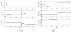
图3(a)是本发明一个实施例提供的转位法纠偏时南北走向井轨迹的陀螺仪常值漂移估计误差曲线图;Fig. 3 (a) is the gyroscope constant value drift estimation error curve diagram of the north-south trending well trajectory when the indexing method provided by an embodiment of the present invention is corrected;
图3(b)是本发明一个实施例提供的转位法纠偏时南北走向井轨迹的加速度计常值漂移估计误差曲线图;Fig. 3 (b) is the accelerometer constant value drift estimation error curve diagram of the north-south trending well trajectory when the indexing method provided by an embodiment of the present invention corrects deviation;
图4是本发明一个实施例提供的转位法纠偏时井轨迹东西走向时水平姿态与方位对准失准角曲线图;4 is a curve diagram of misalignment angle between horizontal attitude and azimuth alignment when the well trajectory runs east-west during deviation correction provided by an embodiment of the present invention;
图5(a)是本发明一个实施例提供的转位法纠偏时东西走向井轨迹的陀螺仪常值漂移估计误差曲线图;Fig. 5 (a) is the gyroscope constant value drift estimation error curve diagram of the east-west well trajectory when the indexing method provided by an embodiment of the present invention corrects deviation;
图5(b)是本发明一个实施例提供的转位法纠偏时东西走向井轨迹的加速度计常值漂移估计误差曲线图;Figure 5(b) is a graph of the accelerometer constant drift estimation error curve of the east-west well trajectory when the indexing method is provided by an embodiment of the present invention for deviation correction;
图6是本发明一个实施例提供的双位置纠偏方法不同常值漂移误差下得到的全井斜方位对准精度曲线图;6 is a graph of the alignment accuracy of full well inclination and azimuth obtained under different constant drift errors of the dual-position deviation correction method provided by an embodiment of the present invention;
图7是本发明一个实施例提供的双位置卡尔曼滤波算法的流程图;7 is a flowchart of a dual-position Kalman filtering algorithm provided by an embodiment of the present invention;
图8是本发明一个实施例提供的双位置卡尔曼算法序贯处理方法流程图;8 is a flowchart of a sequential processing method for a dual-position Kalman algorithm provided by an embodiment of the present invention;
图9是本发明一个实施例提供的双位置+卡尔曼对准流程示意图;9 is a schematic diagram of a dual-position + Kalman alignment process provided by an embodiment of the present invention;
图10是本发明一个实施例提供的双位置+卡尔曼对准法纠偏时南北走向井轨迹失准角误差曲线图;Fig. 10 is the error curve of the misalignment angle of the well trajectory in the north-south trend when the dual-position + Kalman alignment method is provided by an embodiment of the present invention;
图11(a)是本发明一个实施例提供的双位置+卡尔曼对准法纠偏时南北走向井轨迹陀螺仪漂移估计误差图;Figure 11(a) is a diagram of the drift estimation error of the north-south trending well trajectory gyroscope when the dual-position + Kalman alignment method is provided by an embodiment of the present invention;
图11(b)是本发明一个实施例提供的双位置+卡尔曼对准法纠偏时南北走向井轨迹陀螺仪漂移估计误差图;Figure 11(b) is a diagram of the drift estimation error of the north-south well trajectory gyroscope when the dual-position + Kalman alignment method is provided by an embodiment of the present invention;
图12是本发明一个实施例提供的双位置+卡尔曼对准法纠偏时竖直井失准角误差曲线图;12 is a graph of the misalignment angle error curve of a vertical well when the dual-position + Kalman alignment method is provided by an embodiment of the present invention;
图13(a)是本发明一个实施例提供的双位置+卡尔曼对准法纠偏时竖直井陀螺仪漂移估计误差曲线图;Figure 13(a) is a graph of the drift estimation error curve of the vertical well gyroscope when the dual position + Kalman alignment method is provided by an embodiment of the present invention;
图13(b)是本发明一个实施例提供的双位置+卡尔曼对准法纠偏时竖直井加速度计漂移估计误差曲线图;Fig. 13(b) is a graph of the drift estimation error curve of the vertical well accelerometer when the dual position + Kalman alignment method is provided by an embodiment of the present invention;
图14(a)是本发明一个实施例提供的双位置+卡尔曼对准法纠偏时东西向井轨迹小井斜失准角估计误差曲线图;Fig. 14(a) is a curve diagram of estimation error of small well inclination misalignment angle of east-west well trajectory when the dual-position + Kalman alignment method is provided by an embodiment of the present invention;
图14(b)是本发明一个实施例提供的双位置+卡尔曼对准法纠偏时东西向井轨迹大井斜失准角估计误差曲线图;Fig. 14(b) is a curve diagram of the estimation error of the misalignment angle of the east-west well trajectory with large inclination when the dual-position + Kalman alignment method is provided by an embodiment of the present invention;
图15(a)是本发明一个实施例提供的双位置+卡尔曼对准法纠偏时东西向井轨迹70°大井斜角下陀螺仪的常值漂移估计误差图;Figure 15(a) is a graph of the constant drift estimation error of a gyroscope under a large well inclination angle of 70° in the east-west well trajectory when the dual-position + Kalman alignment method is provided by an embodiment of the present invention;
图15(b)是本发明一个实施例提供的双位置+卡尔曼对准法纠偏时东西向井轨迹70°大井斜角下加速度计的常值漂移估计误差图;Fig. 15(b) is a graph of the constant drift estimation error of the accelerometer under a large well inclination angle of 70° in the east-west well trajectory when the dual-position + Kalman alignment method is provided by an embodiment of the present invention;
图16是本发明一个实施例提供的双位置+卡尔曼对准法纠偏时东西向井轨迹全井斜角下GMD对准失准角误差仿真曲线图;16 is a simulation curve diagram of GMD alignment misalignment angle error under the full well inclination angle of the east-west well trajectory when the dual-position + Kalman alignment method is provided by an embodiment of the present invention;
图17(a)是本发明一个实施例提供的双位置+卡尔曼对准法纠偏时东西向井轨迹全井斜角下陀螺仪常值漂移估计误差曲线图;Fig. 17(a) is a graph showing the estimation error of gyroscope constant drift under the full inclination angle of the east-west well trajectory when the dual-position + Kalman alignment method is provided by an embodiment of the present invention;
图17(b)是本发明一个实施例提供的双位置+卡尔曼对准法纠偏时东西向井轨迹全井斜角下加速度计常值漂移估计误差曲线图;Fig. 17(b) is a curve diagram of accelerometer constant drift estimation error under the full well inclination angle of the east-west well trajectory when the dual-position + Kalman alignment method is provided by an embodiment of the present invention;
图18是标准捷联惯导系统的姿态测量原理图;Figure 18 is a schematic diagram of the attitude measurement of the standard strapdown inertial navigation system;
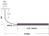
图19是本发明提供的导向钻井:水平井示意图。Fig. 19 is a schematic diagram of the steerable drilling provided by the present invention: a horizontal well.
【具体实施方式】【Detailed ways】
为了更好的理解本发明的技术方案,下面结合附图对本发明实施例进行详细描述。In order to better understand the technical solutions of the present invention, the embodiments of the present invention are described in detail below with reference to the accompanying drawings.
应当明确,所描述的实施例仅仅是本发明一部分实施例,而不是全部的实施例。基于本发明中的实施例,本领域普通技术人员在没有作出创造性劳动前提下所获得的所有其它实施例,都属于本发明保护的范围。It should be understood that the described embodiments are only some, but not all, embodiments of the present invention. Based on the embodiments of the present invention, all other embodiments obtained by those of ordinary skill in the art without creative efforts shall fall within the protection scope of the present invention.
在本发明实施例中使用的术语是仅仅出于描述特定实施例的目的,而非旨在限制本发明。在本发明实施例和所附权利要求书中所使用的单数形式的“一种”、“所述”和“该”也旨在包括多数形式,除非上下文清楚地表示其他含义。The terms used in the embodiments of the present invention are only for the purpose of describing specific embodiments, and are not intended to limit the present invention. As used in the embodiments of the present invention and the appended claims, the singular forms "a," "the," and "the" are intended to include the plural forms as well, unless the context clearly dictates otherwise.
针对现有技术的不足,本发明姿态测量方法,采用卡尔曼+多位置(尤其双位置)+零速的方法进行大井斜角的校准,并对恒定角速度进行修正。如图19所示,水平井包含了:竖直(井)段、靶前位移(斜井段)、水平(井)段,其中定义竖直段的井斜角为0°,靶前位移(斜井段)是指井斜角大于0°到90°这个区段,通常又分为小井斜角(如0°~20°)和大井斜角(如大于70°),没有明确的定义,一般是业内俗称,水平段是指井斜角为90°这一段。定义全井斜,是指涵盖了从竖直段到水平段,井斜角从0°到90°。双位置是其中的一种实现方案,实际任何位置都可以。从机械结构设计的角度来说,双位置对准,方便机械结构设计,即通过机械止档的设计,实现准确的两点定位。In view of the deficiencies of the prior art, the attitude measurement method of the present invention adopts the method of Kalman+multi-position (especially dual-position)+zero speed to calibrate the large inclination angle and correct the constant angular velocity. As shown in Figure 19, a horizontal well includes: vertical (well) section, front displacement (inclined well section), and horizontal (well) section, where the inclination angle of the vertical section is defined as 0°, and the front displacement ( Inclined well section) refers to the section with a well inclination angle greater than 0° to 90°, and is usually divided into small well inclination angles (such as 0° to 20°) and large well inclination angles (such as greater than 70°). There is no clear definition. Generally, it is commonly known in the industry, and the horizontal section refers to the section where the inclination angle of the well is 90°. The definition of full inclination refers to covering from vertical section to horizontal section, and the inclination angle is from 0° to 90°. Dual location is one such implementation, and virtually any location will do. From the perspective of mechanical structure design, dual-position alignment is convenient for mechanical structure design, that is, through the design of mechanical stops, accurate two-point positioning is achieved.
本发明测量方法推理逻辑如下:The reasoning logic of the measurement method of the present invention is as follows:
1:陀螺仪导向的基本原理1: The basic principle of gyroscope guidance
陀螺导向是基于陀螺罗盘原理(Gyrocompass)原理,主要是使用惯性器件(加速度计与陀螺仪)去测量地球自转角速率矢量与重力加速度矢量,从而计算出载体与地理北向的夹角。Gyro guidance is based on the principle of Gyrocompass, which mainly uses inertial devices (accelerometers and gyroscopes) to measure the angular rate vector of the earth's rotation and the vector of gravitational acceleration, so as to calculate the angle between the carrier and the geographic north direction.
地球的自转角速率ωie为固定值15.041067°/h(约0.0042°/s),被测载体所处位置的经度与纬度分别为λ和L,采用“东北天”地理坐标系。The rotation angular rate ωie of the earth is a fixed value of 15.041067°/h (about 0.0042°/s), the longitude and latitude of the measured carrier are λ and L respectively, and the "Northeast Sky" geographic coordinate system is used.
根据陀螺导向的原理,地球自转角速率的水平分量为ωN,其大小取决于测量地点的纬度L。According to the principle of gyroscopic guidance, the horizontal component of the angular rate of the Earth's rotation is ωN , and its magnitude depends on the latitude L of the measurement site.
ωN=ωie cos L (1.1)ωN = ωie cos L (1.1)
如在北京纬度是40°,地球自转的水平分量约为11.52°/h,纬度越高水平分量越小,接近极点位置水平分量趋于零。If the latitude of Beijing is 40°, the horizontal component of the earth's rotation is about 11.52°/h. The higher the latitude, the smaller the horizontal component, and the horizontal component near the pole tends to zero.
假设陀螺仪的敏感轴与载体运动方向同相,定义方位角ψ为陀螺仪敏感轴与北向夹角,则得到陀螺仪的输出值为:Assuming that the sensitive axis of the gyroscope is in phase with the moving direction of the carrier, and the azimuth angle ψ is defined as the angle between the sensitive axis of the gyroscope and the north direction, the output value of the gyroscope is obtained:
ωob=ωNcosψ+B=ωie cosLcosψ+B (1.2)ωob = ωN cosψ+B=ωie cosLcosψ+B (1.2)
式(1.2)中,ωob为陀螺仪的输出值,即观测值,B为陀螺仪的零偏。In formula (1.2), ωob is the output value of the gyroscope, that is, the observation value, and B is the zero bias of the gyroscope.
求解式(1.2),就可以计算得到载体的方位角ψ,此外,由式(1.2)可知,陀螺仪的测量数据包含了陀螺仪本身的零偏B,其值的大小会直接影响方位角计算结果,通常通过多点转位或者连续旋转调制等方式消除,图1给出了单轴陀螺仪通过转位机构旋转改变其敏感方向工作原理示意,为了方便转位机构机械设计,采用简单的0°、180°两位置转位方法,陀螺仪的输出分别为:Solving equation (1.2), the azimuth angle ψ of the carrier can be calculated. In addition, it can be seen from equation (1.2) that the measurement data of the gyroscope includes the zero offset B of the gyroscope itself, and its value will directly affect the azimuth angle calculation. As a result, it is usually eliminated by multi-point indexing or continuous rotation modulation. Figure 1 shows the working principle of a single-axis gyroscope changing its sensitive direction through the rotation of the indexing mechanism. In order to facilitate the mechanical design of the indexing mechanism, a simple 0 °, 180 ° two-position indexing method, the output of the gyroscope is:
ωob(0)=U1/SF1=ωie cosLcosψ+B1 (1.3)ωob (0)=U1 /SF1 =ωie cosLcosψ+B1 (1.3)
ωob(180)=U2/SF2=-ωie cosLcosψ+B2 (1.4)ωob (180)=U2 /SF2 =-ωie cosLcosψ+B2 (1.4)
式(1.3)、(1.4)中,SF1、SF2,U1、U2,B1、B2分别是指在0°和180°位置下陀螺仪的标度因子、输出(模拟量或者数字量)和零偏。In formulas (1.3) and (1.4), SF1 , SF2 , U1 , U2 , B1 , B2 refer to the scale factor, output (analog or digital quantity) and zero offset.
设定GMD寻北的精度为1°,忽略陀螺仪的标度因子误差,由(1.3)、(1.4)可得到单轴陀螺仪的方位测量估计为:The accuracy of GMD north finding is set to 1°, ignoring the scale factor error of the gyroscope, the azimuth measurement estimate of the single-axis gyroscope can be obtained from (1.3) and (1.4):

式(1.5)中,εB是转位补偿后的残余漂移误差,对上式取泰勒展开并忽略高阶项,得到两位置下的估计误差(精度)为In Equation (1.5), εB is the residual drift error after indexing compensation. Taking Taylor expansion of the above equation and ignoring the high-order terms, the estimated error (accuracy) under two positions is obtained as

从式(1.6)可知,采用单陀螺两位置转位时,转位的两个位置选择在东西向附近(ψ1=90°、270°)估计误差最小,此时的估计误差为:From formula (1.6), it can be seen that when the single gyro is used for two-position indexing, the two positions of the indexing are selected near the east-west direction (ψ1 =90°, 270°). The estimation error is the smallest. The estimation error at this time is:

式(1.7)给出了陀螺仪寻北估计精度误差的基本公式,可以看出,两位置转位的寻北精度与陀螺仪的残余漂移误差、当地的纬度相关。Equation (1.7) gives the basic formula of the accuracy error of the gyroscope's north finding estimation. It can be seen that the north finding accuracy of the two-position inversion is related to the residual drift error of the gyroscope and the local latitude.
2:导向原理(初始对准方法)2: Guidance principle (initial alignment method)
导向原理采用欧拉角解析法,欧拉角解析法利用陀螺和加速度计信息直接求取载体的俯仰角(井斜角)θ,横滚角(工具面)γ和航向角(方位角)ψ,在给出本发明解析双位置对准以及双位置卡尔曼最优估计对准方案之前,首先利用欧拉角分析方法,给出粗对准的原理与精度极限。The steering principle adopts the Euler angle analysis method. The Euler angle analysis method uses the gyro and accelerometer information to directly obtain the carrier's pitch angle (inclination angle) θ, roll angle (tool face) γ and heading angle (azimuth angle) ψ , before the analytical dual-position alignment and the dual-position Kalman optimal estimation alignment scheme of the present invention are given, the principle and accuracy limit of the rough alignment are given first by using the Euler angle analysis method.
由于钻井施工地点地理位置已知,此时就能准确获取地球自转角速度矢量在地理坐标系的分量和重力矢量,如下式:Since the geographic location of the drilling construction site is known, the components of the earth's rotation angular velocity vector in the geographic coordinate system and the gravity vector can be accurately obtained at this time, as follows:

其中,g、ωie、L分别表示当地重力加速度大小、地球自转角速率大小和当地纬度,记地球自转角速度的北向分量ωN=ωie cos L和天向分量ωU=ωie sin L。Among them, g, ωie , and L represent the magnitude of the local gravitational acceleration, the magnitude of the angular velocity of the earth's rotation and the local latitude, respectively, and the north component of the angular velocity of the earth's rotation ωN = ωie cos L and the sky component ωU = ωie sin L are recorded.
在静基座粗对准过程中,GMD系统中陀螺和加速度计测量到的分别是重力矢量和地球自转角速度在载体系下的投影,忽略泥浆晃动干扰的影响,载体上三分量陀螺仪与三分量加速度的量测数据为:During the rough alignment of the static base, what the gyroscope and accelerometer measure in the GMD system are the projections of the gravity vector and the angular velocity of the earth's rotation under the carrier system, ignoring the influence of mud shaking, the three-component gyroscope on the carrier and the three-component gyroscope The measured data of the component acceleration is:


其中,in,

粗对准时间一般都很短,惯性仪表的量测数据值一般取一段时间内的平滑均值,在惯性仪表无明显的趋势项漂移误差时,平滑时间越长,越能获得比较好的精度,在综合考虑粗对准时间与对准精度的情况下,平滑的时间长短可以通过对Allan方差测试数据进行判断分析,平滑的最优时间选取依据是Allan方差“触底”的时间。The rough alignment time is generally very short, and the measurement data value of the inertial instrument generally takes the smoothed average value within a period of time. When the inertial instrument has no obvious trend item drift error, the longer the smoothing time, the better the accuracy can be obtained. In the case of comprehensively considering the rough alignment time and the alignment accuracy, the length of the smoothing time can be judged and analyzed by the Allan variance test data.
由式(2.3),可求得俯仰角By formula (2.3), the pitch angle can be obtained

求得横滚角get the roll angle

在获得


求解方位角为Solving the azimuth is

式(2.4)、(2.5)、(2.7)即构成了欧拉角粗对准的基本算法,下面分析欧拉解析方法静基座对准的极限精度。Equations (2.4), (2.5) and (2.7) constitute the basic algorithm of Euler angle rough alignment. The limit accuracy of the static base alignment of the Euler analytical method is analyzed below.
考虑加速度计和陀螺仪的零偏误差:Consider the bias errors of the accelerometer and gyroscope:

式(2.8)中,
求解一个方向微分时并令另外两个方向角度为零,分别对(2.4)、(2.5)、(2.7)两边进行微分并忽略二阶小量得,When solving the differential of one direction and set the other two directions to zero, differentiate the two sides of (2.4), (2.5), (2.7) respectively and ignore the second-order small quantities, we get,


式(2.9)、(2.10)和(2.11)确定了静基座对准的极限精度,即为粗对准的解析法的公式,通过加速度计与陀螺仪的数据直接进行计算即可。静基座条件下的姿态对准精度主要取决于东向与北向的加速度计漂移误差,而方位对准精度主要取决于东向陀螺的漂移误差以及东向加速度计的漂移误差。Equations (2.9), (2.10) and (2.11) determine the limit accuracy of the static base alignment, which is the formula of the analytical method for rough alignment, which can be calculated directly through the data of the accelerometer and gyroscope. The attitude alignment accuracy under the static base condition mainly depends on the drift error of the accelerometer in the east and north directions, while the azimuth alignment accuracy mainly depends on the drift error of the east gyro and the drift error of the east accelerometer.
卡尔曼最优估计中,上标的^号,代表估计值,或者计算值,不带的,就是表示状态值。如,井斜角θ的估计值是
此外,式(2.4)、(2.5)、(2.7)中选取的加速度计与陀螺仪的量测数据值,可以有多种方式,通常会选取一段时间采样值的均值,取样时间和极限精度,通常通过Allan方差的方法进行表述,将Allan方差的最低点作为精度极限的评价,因此,积分时间越长其平滑后的精度越高,但是对于存在趋势项误差或者漂移误差的情况,积分时间的长度取决于漂移误差的时间常数。当存在采样过程中的异常数据,或者此时钻铤的意外扰动时,带来了测量误差,这也是粗对准的最大风险和问题。In addition, the measurement data values of the accelerometers and gyroscopes selected in equations (2.4), (2.5) and (2.7) can be measured in various ways. Usually, the average value of the sampling values over a period of time, the sampling time and the limit accuracy are selected. It is usually expressed by the method of Allan variance, and the lowest point of the Allan variance is used as the evaluation of the accuracy limit. Therefore, the longer the integration time, the higher the smoothed accuracy, but for the existence of trend term error or drift error, the integration time The length depends on the time constant of the drift error. When there are abnormal data in the sampling process, or unexpected disturbance of the drill collar at this time, measurement errors are brought, which is also the biggest risk and problem of rough alignment.
3:转位置index消除常值零偏的方法与原理(即双位置消零偏方法)3: The method and principle of removing the constant zero offset by turning the position index (that is, the two-position zero offset method)
传统消除漂移误差、提高方位对准精度的方法是采用转位置index。The traditional method to eliminate drift error and improve azimuth alignment accuracy is to use the rotation position index.
假定惯性仪表的常值零偏在转位前后数值不变,并忽略转动前后位置的角运动和线运动干扰,通过绕一个方向转动IMU,从而构造两个位置下的姿态转移矩阵,增加常值零偏的可观测性。实际应用中,受限于惯性仪表的尺寸与GMD探管的细长杆尺寸特性,转位机构的设计只能是绕探管的轴向,也就是绕Z轴陀螺仪的输入轴方向。Assuming that the constant zero bias of the inertial instrument remains unchanged before and after the indexing, and ignores the angular motion and linear motion interference before and after the rotation, by rotating the IMU in one direction, the attitude transfer matrix in two positions is constructed, and the constant zero is added. biased observability. In practical applications, limited by the size of the inertial instrument and the slender rod size characteristics of the GMD probe, the design of the indexing mechanism can only be around the axis of the probe, that is, around the input axis of the Z-axis gyroscope.
陀螺仪转位前后位置是b1和b2,在对准时间内对应的陀螺仪的采样输出均值分别为


则b1位置和b2位置惯性仪表输出之间存在关系式:Then there is a relationship between the inertial meter output of the b1 position and the b2 position:

考虑到转位过程时间很短,忽略随机常值中的一阶马尔科夫过程,并认为转位前后惯性仪表的常值漂移不变,只考虑随机漂移的影响,此外,由于陀螺仪绕Z轴旋转,Z轴陀螺仪与加速度计转位前后敏感方向不变,无法实现Z轴常值漂移的分离,当只考虑水平轴惯性仪表的输出时,Considering that the time of the transposition process is very short, the first-order Markov process in the random constant value is ignored, and the constant value drift of the inertial instrument before and after the transposition is considered unchanged, and only the influence of random drift is considered. When the axis rotates, the sensitive direction of the Z-axis gyroscope and accelerometer remains unchanged before and after the transposition, and the separation of the Z-axis constant drift cannot be realized. When only the output of the horizontal axis inertial instrument is considered,

式(3.2)可得b2位置的水平陀螺输出为:Equation (3.2) can obtain the output of the horizontal gyro at position b2 as:

同样可得b2位置的水平加速度计的输出为:Similarly, the output of the horizontal accelerometer at position b2 can be obtained as:

式(3.3、(3.4)可以得出,理论上任何微小转角β都可以分离出水平惯性仪表的常值漂移,当转角β为180°时,

水平加速度计零偏估计值为:The estimated value of the horizontal accelerometer zero bias is:

求得双位置校准后加速度计的估计值为:The estimated value of the accelerometer after two-position calibration is obtained as:

双位置校准后陀螺仪的估计值为:The estimated value of the gyroscope after dual position calibration is:

而Z轴的加速度计与陀螺仪不可观测,直接取转位前后的均值作为校准后的估计值:The Z-axis accelerometer and gyroscope cannot be observed, and the mean value before and after the transposition is directly taken as the estimated value after calibration:

根据校正后的陀螺仪与加速度计的估计值,采用类似于单位置欧拉角解析粗对准原理,可求得校准后的倾角为:According to the estimated values of the gyroscope and accelerometer after correction, and adopting the principle of analytical rough alignment similar to the single-position Euler angle, the calibrated inclination angle can be obtained as:

校准后的工具面角为:The calibrated tool face angle is:

校准后的方位角为:The calibrated azimuth is:

式(3.7)~(3.9)构成了绕Z轴转位180°解析双位置对准的基本算法。Equations (3.7) to (3.9) constitute the basic algorithm for analysing two-position alignment by 180° indexing around the Z-axis.
解析双位置解决了惯性仪表常值漂移误差校准的问题,提高了对准精度尤其是方位对准精度,对于小倾角测量,对准的主要误差来源于转位机构的误差与惯性仪表的随机漂移误差,由于采用0-180°转位设计,只关注最终的转位定位精度,方便了转位机构的设计,在实际应用中,可以通过止档结构设计提高转位定位精度,简化了设计;对于随机漂移误差,假设每个位置的对准时间都是t,测试得到的陀螺仪的随机游走系数为


对于定向钻进测量应用,大井斜角以及不同的轨迹方向下,通过仿真分析双位置解析法能够测量的精度极限与误差机理,仿真过程如下:For directional drilling measurement applications, under large well inclination and different trajectory directions, the accuracy limit and error mechanism that can be measured by the dual-position analytical method are analyzed by simulation. The simulation process is as follows:
陀螺仪与加速度计的误差参数如表1高温惯性仪表仿真参数设置,设置初始位置为[116°E,40°N,100m],在前145s处于第一对准位置,在146~155s期间沿着探管Z轴方向转动180°至第二位置,然后继续对准145s,对准总时间300s,井斜角在0~90°范围,每1°取一位置,共91个位置,每个位置做40次Monte-Carlo仿真并取均方根值。The error parameters of the gyroscope and the accelerometer are shown in Table 1. The high-temperature inertial instrument simulation parameters are set. Rotate the probe tube 180° in the Z-axis direction to the second position, and then continue to align for 145s. The total alignment time is 300s. The inclination angle is in the range of 0 to 90°, and a position is taken every 1°. There are 91 positions in total. 40 Monte-Carlo simulations were performed for the position and the root mean square value was taken.
表1 高温惯性仪表仿真参数设置表Table 1 High temperature inertial instrument simulation parameter setting table

仿真一:井轨迹为南北走向,地理坐标系下的竖直井姿态方位[0°,0°,0°],水平井姿态方位为[90°,0°,0°],图2为对准失准角误差曲线,图3(a)和图3(b)依次为陀螺仪与加速度计的常值漂移估计误差。Simulation 1: The well trajectory is north-south, the vertical well attitude azimuth under the geographic coordinate system is [0°, 0°, 0°], and the horizontal well attitude azimuth is [90°, 0°, 0°]. The quasi-misalignment error curve, Figure 3(a) and Figure 3(b) are the constant drift estimation errors of the gyroscope and the accelerometer in turn.
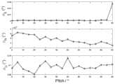
从图2可以看出,当被测井轨迹是南北走向时,方位对准精度不受井斜角的影响,也就是从竖直井段到水平井段,方位测量误差始终保持在0.1°附近,这也是符合公式(2.11)的结论,从初始对准的机理也不难理解,方位失准角与等效东向陀螺的精度相关,由于在南北走向时,从竖直井段到水平井段,东向陀螺仪始终能够被转位调制,也就是东西陀螺仪的常值漂移始终可观测,也就是通过转位的方式在任何井斜角下均可以消除等效东向陀螺的常值漂移。最终方位对准精度主要是取决于东向陀螺仪的随机漂移,图2仿真结果可以验证此结论。此外,图2中的东向失准角与图3(b)中的Z轴加速度计的估计误差曲线,可以看出Z轴加速度计随着倾角的增大,可观测性变差,当Z轴向南北方向倾斜时,导致了东向失准角误差随着倾角的增大而增大,但是其误差远小于目标精度指标,该项影响可以忽略。It can be seen from Figure 2 that when the logging trajectory is north-south, the azimuth alignment accuracy is not affected by the inclination angle, that is, from the vertical well section to the horizontal well section, the azimuth measurement error always remains around 0.1° , which is also in line with the conclusion of formula (2.11). It is not difficult to understand from the initial alignment mechanism. The azimuth misalignment angle is related to the accuracy of the equivalent east gyro. In this segment, the easting gyroscope can always be modulated by indexing, that is, the constant drift of the east-west gyroscope can always be observed, that is, the constant value of the equivalent easting gyroscope can be eliminated at any inclination angle by means of indexing. drift. The final azimuth alignment accuracy mainly depends on the random drift of the east gyroscope. The simulation results in Figure 2 can verify this conclusion. In addition, from the eastward misalignment angle in Figure 2 and the estimated error curve of the Z-axis accelerometer in Figure 3(b), it can be seen that the observability of the Z-axis accelerometer becomes worse as the inclination angle increases. When the axis is tilted in the north-south direction, the eastward misalignment angle error increases with the increase of the inclination angle, but the error is much smaller than the target accuracy index, and this effect can be ignored.
仿真二:井轨迹为东西走向。地理坐标系下,竖直井姿态方位坐标为[0°,0°,90°],水平井姿态方位坐标为[90°,0°,90°],仿真结果如图4所示。Simulation 2: The well trajectory is east-west. In the geographic coordinate system, the vertical well attitude and azimuth coordinates are [0°, 0°, 90°], and the horizontal well attitude and azimuth coordinates are [90°, 0°, 90°]. The simulation results are shown in Figure 4.
由图4可知,当井轨迹是东向走向时,随着井斜角的增大,方位失准角的估计误差也明显增加,最为主要的原因是当井斜角增大,Z轴陀螺仪成为东向陀螺仪的误差的主要贡献者,而转位是绕Z轴旋转的,Z轴的常值漂移本身不可观测,从而直接造成了方位失准角的误差,从图4还可以看出,为了保证方位测量精度优于1°,则井斜角不能超过10°。It can be seen from Fig. 4 that when the well trajectory is eastward, with the increase of the well inclination, the estimation error of the azimuth misalignment angle also increases significantly. The main reason is that when the well inclination increases, the Z-axis gyro It becomes the main contributor to the error of the eastward gyroscope, and the transposition rotates around the Z axis. The constant drift of the Z axis itself cannot be observed, which directly causes the error of the azimuth misalignment angle. It can also be seen from Figure 4 , in order to ensure that the azimuth measurement accuracy is better than 1°, the inclination angle cannot exceed 10°.
对于双位置解析式对准,可以通过降低陀螺仪的常值漂移来提高大倾角下的方位测量精度,图6给出了不同常值漂移下的陀螺仪在不同倾角下的方位测量精度仿真曲线,可以看出,井轨迹测量精度要求是1°时,为了保证在大井斜角下的精度,要求陀螺仪的常值漂移小于0.2deg/h,而对于高温、强振动恶劣环境下的工况,零偏重复性误差是制约陀螺仪精度的主要瓶颈,研制满足使用工况下的0.2deg/h常值漂移误差的陀螺仪是非常有挑战的。For dual-position analytical alignment, the azimuth measurement accuracy at large inclination angles can be improved by reducing the constant drift of the gyroscope. Figure 6 shows the simulation curve of the azimuth measurement accuracy of the gyroscope at different inclination angles under different constant drifts. , it can be seen that when the well trajectory measurement accuracy is required to be 1°, in order to ensure the accuracy under large well inclination, the constant drift of the gyroscope is required to be less than 0.2deg/h. , the zero-bias repeatability error is the main bottleneck restricting the accuracy of the gyroscope, and it is very challenging to develop a gyroscope that meets the 0.2deg/h constant drift error under operating conditions.
对于解析式双位置对准,在惯性器件精度一定的前提下,通过转位校准的方式,可以有效地提升东西轨迹下小井斜角以及全井斜角(0°~90°)南北走向轨迹的方位精度,但对于大井斜角下的东西走线的方位精度仍然不能满足使用要求,因此丞待一种更为有效的方法,在惯性器件精度受限的情况下,提升大井斜角的方位测量精度。For analytical dual-position alignment, under the premise of a certain inertial device accuracy, the indexing calibration method can effectively improve the small well inclination under the east-west trajectory and the full well inclination (0°~90°) of the north-south trajectory. Azimuth accuracy, but the azimuth accuracy of the east-west line under large inclination angle still can not meet the requirements of use, so a more effective method is needed to improve the azimuth measurement of large inclination angle when the accuracy of inertial devices is limited. precision.
4:双位置+卡尔曼的对准方法4: Alignment method of dual position + Kalman
本发明采用多位置+卡尔曼的对准方法来解决大倾角下东向陀螺的测漂问题。The invention adopts the alignment method of multi-position + Kalman to solve the drift measurement problem of the east gyro under the large inclination angle.
该方法的内容包括:The content of this method includes:
导航坐标系取为东北天地理坐标系,建立12维惯导系统精对准数学模型,卡尔曼滤波器的状态变量为:The navigation coordinate system is taken as the geographic coordinate system of the northeast sky, and a 12-dimensional inertial navigation system precise alignment mathematical model is established. The state variables of the Kalman filter are:

式(4.1)中分别为:速度误差δvn、捷联惯导数学平台失准角φn、高温陀螺常值漂移


上式中,In the above formula,

式(4.3)中


GMD系统(Gyro Measurement while Drilling System,陀螺仪随钻测量系统)静基座对准时载体静止,导航解算的输出速度vn即为速度误差δvn,将δvn作为量测数据,则量测方程为:When the static base of the GMD system (Gyro Measurement while Drilling System) is aligned, the carrier is stationary, and the output velocity vn of the navigation solution is the velocity error δvn , and δvn is used as the measurement data, then the measurement The equation is:
Zv=δvn=HvX+Vv (4.4)Zv =δvn =Hv X+Vv (4.4)
其中,Vv为导航坐标系中的速度量测噪声,δvn为速度误差,I表示单位矩阵,X代表卡尔曼滤波状态变量;Zν表示速度观测量,Hv=[I3×3 03×3 03×3 03×3]。Among them, Vv is the velocity measurement noise in the navigation coordinate system, δvn is the velocity error, I is the identity matrix, X is the Kalman filter state variable; Zν is the velocity observation, Hv =[I3×3 03×3 03×3 03×3 ].
单位置卡尔曼对准的可观测性理论分析相对成熟,采用静基座下卡尔曼最优估计对准方式,φU、εN、εU可观测性弱,而
对于导向钻进测量应用,当前高温的石英挠性加速度计的精度基本能够满足静基座下姿态对准精度要求,陀螺仪的精度尤其是逐次启动的重复性误差成为制约方位对准精度的核心因素。方位测量的精度提高有多种途径,一方面,是惯性仪表本身精度的提升,从根本上去解决影响重复性误差的因素,如惯性仪表的敏感单元精密加工、静平衡与动平衡、材料特性优化、控制电路优化等,但是存在研发周期长、成本代价高等问题;另一方面,从校准的角度,利用当前惯性仪表的特性,通过外部校准或者内部校准,从而实现提高惯性系统精度的目的,而外部校准,通常采用多位置转位+卡尔曼算法的方式进行校准。For the application of steered drilling measurement, the accuracy of the current high-temperature quartz flexible accelerometer can basically meet the requirements of the attitude alignment accuracy under the static base, and the accuracy of the gyroscope, especially the repeatability error of successive starts, has become the core restricting the accuracy of the azimuth alignment. factor. There are many ways to improve the accuracy of azimuth measurement. On the one hand, it is the improvement of the accuracy of the inertial instrument itself, which fundamentally solves the factors that affect the repeatability error, such as the precision machining of the sensitive unit of the inertial instrument, static balance and dynamic balance, and optimization of material properties. , control circuit optimization, etc., but there are problems of long development cycle and high cost; on the other hand, from the perspective of calibration, using the characteristics of the current inertial instrument, through external calibration or internal calibration, so as to achieve the purpose of improving the accuracy of the inertial system, while External calibration, usually using multi-position index + Kalman algorithm for calibration.
双位置对准方法从本质上是属于静基座欧拉角初始对准,解析双位置对准无法实现惯性仪表误差的最优估计,尤其是在东西方向井轨迹下,由图4可知,当倾角大于10°时,方位对准精度急剧变差。此外,由于解析法只是通过拾取一段时间的载体上惯性仪表的输出信息作为观测量,其对准精度受限于载体在采样时间段内的静止无晃动的理想程度,由于GMD工作于停钻寻北状态时,泥浆马达可能还在工作,当泥浆晃动引起的干扰角速率大于地球自转角速率时,解析双位置对准无法正常工作。基于最优估计的卡尔曼多位置对准,具有信息的容错能力,具有微小晃动下对准的能力,并能够在不改变惯性仪表本身的精度基础上,提升了惯性仪表误差的可观测性,实现了惯性仪表误差的最优估计,从而提高初始对准精度。受限于探管的狭小尺寸,绕探管轴向的两位置转位是本发明的优选方案。The dual-position alignment method is essentially a static base Euler angle initial alignment. Analytical dual-position alignment cannot achieve the optimal estimation of the inertial instrument error, especially under the east-west well trajectory. It can be seen from Figure 4 that when When the inclination angle is greater than 10°, the azimuth alignment accuracy deteriorates sharply. In addition, since the analytical method only picks up the output information of the inertial instrument on the carrier for a period of time as the observation value, its alignment accuracy is limited by the ideal degree of the carrier being stationary without shaking during the sampling period. In the north state, the mud motor may still be working. When the disturbance angular rate caused by mud shaking is greater than the earth's rotation angular rate, the analytical dual-position alignment cannot work properly. The Kalman multi-position alignment based on the optimal estimation has the ability of information fault tolerance, the ability to align under slight shaking, and can improve the observability of the inertial instrument error without changing the accuracy of the inertial instrument itself, An optimal estimation of the inertial instrument error is achieved, thereby improving the initial alignment accuracy. Limited by the small size of the probe tube, two-position indexing around the axial direction of the probe tube is the preferred solution of the present invention.
和静基座下卡尔曼最优估计初始对准建立的状态方程一样,双位置卡尔曼最优估计的状态方程如式(4.2),假设转位时间很短,认为常值漂移误差


静基座下的GMD的姿态误差方程如式(4.5)所示:The attitude error equation of the GMD under the static base is shown in formula (4.5):

静基座下GMD的速度误差方程如式(4.6)所示:The velocity error equation of GMD under static base is shown in formula (4.6):

通过转位180°可以实现


根据图18的标准捷联惯导系统方位测量原理可知,当Z轴进行转位置时,根据公式(3.5)-(3.9),X轴陀螺仪、Y轴陀螺仪,可以通过转位的方式分离重复性误差。而当井斜角很大时,尤其是东西走向时,Z轴陀螺仪将成为东向(西向)陀螺仪,而受限于GMD的尺寸,转位机构只能绕Z轴,因此,大倾角下,Z轴陀螺仪将无法通过转位置的方式分离误差系数。此时,如果只有零速度修正,无法实现Z轴陀螺仪的重复性漂移误差的估计。根据式(2.9)、(2.10)、(2.11)可知,方位对准精度主要取决于东向陀螺仪的漂移误差,而此时Z轴陀螺仪漂移误差无法估计,从而使得方位精度无法满足要求。According to the azimuth measurement principle of the standard strapdown inertial navigation system in Figure 18, when the Z-axis is rotated, according to formulas (3.5)-(3.9), the X-axis gyroscope and the Y-axis gyroscope can be separated by indexing. repeatability error. When the inclination angle of the well is large, especially in the east-west direction, the Z-axis gyroscope will become an east (west) gyroscope, and limited by the size of the GMD, the indexing mechanism can only revolve around the Z-axis. Therefore, the large inclination angle In this case, the Z-axis gyroscope will not be able to separate the error coefficients by turning the position. At this time, if there is only zero velocity correction, the estimation of the repeatability drift error of the Z-axis gyroscope cannot be achieved. According to equations (2.9), (2.10), (2.11), the azimuth alignment accuracy mainly depends on the drift error of the east gyroscope, and the Z-axis gyroscope drift error cannot be estimated at this time, so that the azimuth accuracy cannot meet the requirements.
为了实现在大井斜角下Z轴陀螺仪常值漂移误差的估计,需要增加观测量,本文采用静基座下地球自转角速率作为新的观测量,在获取水平姿态的最优估计后,利用载体系在导航系下的投影与导航系下地球角速率的差值作为卡尔曼的观测信息。通过仿真可知,Z轴陀螺仪的漂移误差得到了很好的估计。In order to realize the estimation of the constant drift error of the Z-axis gyroscope under large well inclination, it is necessary to increase the observation amount. In this paper, the earth rotation angular rate under the static base is used as a new observation amount. After obtaining the optimal estimation of the horizontal attitude, use The difference between the projection of the carrier system under the navigation system and the angular velocity of the earth under the navigation system is used as Kalman's observation information. The simulation shows that the drift error of the Z-axis gyroscope is well estimated.
其测量方程如下:Its measurement equation is as follows:

由此得到量测方程为:The resulting measurement equation is:

式(4.8)中,Vω是指角速率量测噪声,Zω表示角速率观测量。In Equation (4.8), Vω refers to the angular rate measurement noise, and Zω represents the angular rate observation amount.
至此,建立了完整的卡尔曼最优估计状态方程(4.2),量测方程如式(4.4)与式(4.8)。So far, the complete Kalman optimal estimation state equation (4.2) has been established, and the measurement equations are shown in equations (4.4) and (4.8).
本部分相关含义说明:The relevant meanings of this part are explained:
惯性仪表的误差模型,静基座下,忽略标度因子误差与安装误差,陀螺在载体坐标系输出模型可以表示为:The error model of the inertial instrument, under the static base, ignoring the scale factor error and installation error, the output model of the gyro in the carrier coordinate system can be expressed as:

其中
根据Allan方差概念,ε0主要是逐次启动的重复性误差,可以用随机常数表示,其误差模型为:According to the concept of Allan variance, ε0 is mainly the repeatability error of successive starts, which can be represented by random constants. The error model is:

慢变漂移εr代表陀螺仪的趋势项,表征Allan方差中的速率斜坡项,通常可以用一阶马尔科夫过程描述,即:The slowly varying drift εr represents the trend term of the gyroscope and characterizes the rate ramp term in the Allan variance, which can usually be described by a first-order Markov process, namely:

式(4.11)中,τg为马尔科夫过程的相关时间,wr是白噪声。In formula (4.11), τg is the correlation time of the Markov process, and wr is white noise.
根据高温陀螺仪样机的Allan方差可得,通过综合误差补偿,抑制了陀螺仪和时间相关的趋势项误差,实现了陀螺仪Allan方差“触底”时间后可以保持较长的时间,因此,实际上马尔科夫相关时间较长,在对准时间内可以忽略不计,陀螺仪的输出模型可简化为:According to the Allan variance of the high-temperature gyroscope prototype, the comprehensive error compensation suppresses the error of the gyroscope and the time-related trend term, and realizes that the Allan variance of the gyroscope can be maintained for a long time after the "bottom" time. Therefore, the actual The upper Markov correlation time is long and can be ignored in the alignment time. The output model of the gyroscope can be simplified as:

其中,陀螺仪的零偏误差为:Among them, the zero bias error of the gyroscope is:
ε=ε0+εw (4.13)ε=ε0 +εw (4.13)
通常用角度随机游走系数ARW表示和白噪声相关的项εw。The term εw associated with white noise is usually represented by the angular random walk coefficientARW .
同样,加速度计输出模型可以简化为:Likewise, the accelerometer output model can be simplified to:

其中,


定义加速度计的零偏误差为:The zero bias error of the accelerometer is defined as:

5:双位置+卡尔曼算法的流程设计5: Process design of dual position + Kalman algorithm
对状态方程(4.2)和量测方程(4.4)与(4.8)离散化,得到GMD静基座下对准的随机系统状态空间模型:By discretizing the state equation (4.2) and the measurement equations (4.4) and (4.8), the state space model of the stochastic system aligned under the GMD static base is obtained:

式(5.1)中,Xk是公式(4.1)所示的12×1维的状态向量(式(4.1)中分别为:速度误差δvn、捷联惯导数学平台失准角φn、高温陀螺常值漂移

E{WkWjT}=Qkδkj;E{Wk WjT }=Qk δkj ;
E{VkVjT}=Rkδkj;E{Vk VjT }=Rk δkj ;
E{WkVjT}=0 (5.2)E{Wk VjT }=0 (5.2)
Qk和Rk分别称为系统噪声和量测噪声的方差矩阵,在卡尔曼滤波中要求它们分别是已知的非负定阵和正定阵,δkj是Kronecker(克罗内克)δ函数,当k≠j时,δkj=0,当k=j时,δkj=1。Qk and Rk are called the variance matrices of system noise and measurement noise, respectively. They are required to be known non-negative definite matrices and positive definite matrices, respectively, in Kalman filtering, and δkj is the Kronecker δ function. , when k≠j, δkj =0, when k=j, δkj =1.
GMD精对准的离散卡尔曼滤波方程可划分为五个基本公式,如下:The discrete Kalman filter equation for GMD precise alignment can be divided into five basic formulas, as follows:
①状态一步预测方程①State one-step prediction equation

②一步预测均方误差方程②One-step forecast mean square error equation

③滤波增益方程③Filter gain equation

④状态估值方程④ State evaluation equation

⑤状态估计均方误差方程⑤ State estimation mean square error equation
Pk/k=(I-KkHk)Pk/k-1 (5.7)Pk/k = (IKk Hk )Pk/k-1 (5.7)
图7为卡尔曼滤波算法的流程图,从图中可以看出,卡尔曼滤波的算法流程可以划分为两个计算回路与两个更新过程,左侧为滤波计算回路,完成被估计状态量的迭代计算,右侧为增益计算回路,完成卡尔曼增益的计算;虚线的上下构成了两个更新过程,在时间更新内,完成状态一步预测


基于卡尔曼最优估计的双位置对准算法采用了捷联惯导姿态更新算法与速度更新算法去实时更新载体的角运动与线运动,采用基于零速和地球自转角速率修正算法进行量测更新和最优估计。因此,最优估计精度与转位的精度无关,也无需知道转位机构的准确位置,这在工程实际中是非常有益的,避免了复杂止档结构的设计,也避免了使用耐高温的测角机构。这是本发明卡尔曼算法+双位置对准方法的特点和优势。The dual-position alignment algorithm based on Kalman optimal estimation uses the strapdown inertial navigation attitude update algorithm and the speed update algorithm to update the angular motion and linear motion of the carrier in real time, and uses the zero speed and the earth rotation angular rate correction algorithm to measure Update and best estimate. Therefore, the optimal estimation accuracy has nothing to do with the accuracy of the indexing, and there is no need to know the exact position of the indexing mechanism, which is very beneficial in engineering practice, avoiding the design of complex stop structures and the use of high-temperature measuring instruments. corner body. This is the characteristic and advantage of the Kalman algorithm + dual-position alignment method of the present invention.
在量测更新过程中,需要求解高维数矩阵逆运算,从而获得卡尔曼滤波增益系数,为了降低运算量,常常采用序贯滤波(Sequential Kalman Filter),分别求解由速度量测Zv与地球自转角速率量测Zω组成的量测矩阵。In the measurement update process, it is necessary to solve the inverse operation of the high-dimensional matrix, so as to obtain theKalman filter gain coefficient. The measurement matrix composed of the rotation angular rate measurement Zω .
GMD双位置精对准采用序贯处理的流程如图8所示。图8中的Zk有效判读,就是判读量测的数据有效性(公式(4.4)和(4.8)),即设定敏感速度或者敏感角速率的判据,去判读此时的钻铤是否处于静止状态或者是否保证其微小的扰动不影响对准的精度。状态变量完成时间更新后,当GMD探管处于静止或者微小扰动状态时,通过采集到的一段时间内的加速度计与陀螺仪的数据,自动判断观测量是否有效,按照序贯处理,分别完成速度量测Zv更新与角速率量测Zω更新,计算卡尔曼增益,实现X、Y水平陀螺仪常值漂移误差最优估计与Z轴陀螺仪常值漂移误差估计(陀螺仪常值漂移误差的最优估计体现在状态矩阵X中包含的陀螺仪与加速度计漂移误差

量测方程有效下的最优估计的最终结果是式(5.6);式(5.7)是估计后对估计效果的评价。式(5.3)到式(5.7)是估计的过程,是一个递推过程。The final result of the optimal estimation when the measurement equation is valid is Equation (5.6); Equation (5.7) is the evaluation of the estimation effect after estimation. Equations (5.3) to (5.7) are the estimation process, which is a recursive process.
GMD系统检测到停钻寻北指令后,开启寻北(初始对准)模式,卡尔曼双位置对准算法基本流程如下:After the GMD system detects the stop-drilling and north-seeking command, it starts the north-seeking (initial alignment) mode. The basic flow of the Kalman dual-position alignment algorithm is as follows:
1)在初始位置1,采用解析法粗对准算法在20s内完成粗对准;1) At the
2)以粗对准的水平姿态角与方位角作为卡尔曼滤波的初值,在位置1进行130s的精对准与惯性仪表的测漂,估计惯性仪表误差与失准角误差,然后以本次对准的结果作为初值进入导航状态;2) Take the roughly aligned horizontal attitude angle and azimuth angle as the initial value of Kalman filter, perform 130s fine alignment and inertial instrument drift measurement at
东北天地理坐标系下,定义的水平姿态角:即为俯仰角和横滚角,对应钻井测量,对应的是井斜角和工具面角;定义的方位角,即为东北天下的方位角,对应钻井测术语,就是方位角或者和地理北向的夹角;Under the northeast sky geographic coordinate system, the defined horizontal attitude angle: namely the pitch angle and the roll angle, corresponding to the drilling measurement, corresponding to the well inclination angle and tool face angle; the defined azimuth angle is the azimuth angle of the northeast sky, Corresponding to the drilling survey term, it is the azimuth angle or the included angle with the geographic north direction;
3)保证转位角速率小于Z轴陀螺仪最大测量量程的前提下,在20s内完成180°位置转动,转至位置2,同时更新姿态、速度导航数据;180°为优选,但是本发明并非只适用于180°转位,而是适用于任意转位;3) Under the premise of ensuring that the indexing angular rate is less than the maximum measurement range of the Z-axis gyroscope, complete 180° position rotation within 20s, turn to
4)在位置2进行130s的精对准,估计水平姿态与方位误差角并完成惯性仪表的测漂;测漂方式本领域有多种方法实现,这里不做赘述。4) Perform precise alignment for 130 s at
整个对准过程可以在约300s内完成,流程如图9所示。The entire alignment process can be completed in about 300s, and the process is shown in Figure 9.
精对准的流程具体为:The precise alignment process is as follows:
步骤1:进行姿态和速度更新;Step 1: Perform attitude and speed updates;
以粗对准的俯仰角、横滚角、航向角(对应钻井的井斜角、工具面角、方位角)为初值,采用导航算法,进行速度更新和姿态更新;Taking the pitch angle, roll angle and heading angle of rough alignment (corresponding to the inclination angle, tool face angle and azimuth angle of drilling) as the initial values, the navigation algorithm is used to update the speed and attitude;
1.1姿态更新的算法为:1.1 The algorithm for attitude update is:
为了更为简单的理解姿态更新与速度更新,这里列出其基本的算法,实际上,作为导航算法,姿态更新与速度更新是现有技术,这里给出一般性的物理数学方法实现:In order to understand the attitude update and speed update more simply, the basic algorithms are listed here. In fact, as a navigation algorithm, attitude update and speed update are existing technologies. Here is a general physical and mathematical method implementation:
四元数法:四元数是一种数学方法,在捷联惯导算法中,它被用来是描述坐标系变换关系和求解姿态矩阵的方便工具。Quaternion method: Quaternion is a mathematical method, which is used as a convenient tool to describe the coordinate system transformation relationship and solve the attitude matrix in the strapdown inertial navigation algorithm.
当刚体绕定点运动的欧拉一次转动定理可知,刚体由一位置到另一位置的有限转动,可以绕通过定点的某一轴转动某一角度的一次转动实现,且此一次转动可用如下单位四元数表示:When Euler's one-rotation theorem of rigid body movement around a fixed point shows that the finite rotation of a rigid body from one position to another can be realized by one rotation of a certain angle around an axis passing through the fixed point, and this rotation can be realized by the following units: four The arity means:

四元数中的q中的角度α表示一次转动的角度,矢量ξ表示一次转动的转轴方位,并以ξ的指向按照右手法则作为转角α的正向。The angle α in q in the quaternion represents the angle of one rotation, the vector ξ represents the orientation of the rotation axis of one rotation, and the direction of ξ is used as the positive direction of the rotation angle α according to the right-hand rule.
四元数与姿态矩阵

因此,已知载体转动的四元数,q0、q1、q2、q3,既可以求得载体坐标系到导航坐标系的变换矩阵
通过载体系b系测量得到的角速率

实时获取载体的角速率矢量,就可以求取四元数,根据公式(a),即可获得载体的姿态方位信息,θ、γ、
在求解公式(b)时,属于微分方程,需要获取四元数的初值,q0(0)、q1(0)、q2(0)、q3(0),通过粗对准对准获取的方位姿态初值定义为:θ0、γ0、
可以求取初始四元数为:The initial quaternion can be obtained as:

通过递推求解四元数微分方程(b),即可不断求取并更新载体的四元数,从而求取载体的姿态转换矩阵,从而实时计算出载体的姿态方位信息,θ、γ、By recursively solving the quaternion differential equation (b), the quaternion of the carrier can be continuously obtained and updated, so as to obtain the attitude transformation matrix of the carrier, so as to calculate the attitude and orientation information of the carrier in real time, θ, γ,

这里的载体,就是需要GMD去测量的钻铤组件。The carrier here is the drill collar assembly that needs to be measured by GMD.
1.2速度更新的算法为:1.2 The algorithm for speed update is:
速度微分方程即比力方程,是惯性导航解算的基本关系式The velocity differential equation is the specific force equation, which is the basic relational formula for inertial navigation solutions.

式中gn=[0 0 -g]T,为重力加速度在导航坐标系中的投影。where gn =[0 0 -g]T , is the projection of the gravitational acceleration in the navigation coordinate system.
式中,fb是指加速度计实时量测得到的载体坐标系b系下的三分量值。式(5.8)中各参数均为向量或矢量。In the formula, fb refers to the three-component value in the carrier coordinate system b system measured by the accelerometer in real time. Each parameter in formula (5.8) is a vector or a vector.


其中vE、vN为东、北向速度;L、h为纬度和高度;Among them, vE and vN are the east and north speed; L and h are the latitude and height;
ωie为地球自转角速率。ωie is the angular rate of the Earth's rotation.
已知纬度L,子午圈曲率半径RM和卯酉圈曲率半径RN可按下式计算:Knowing the latitude L, the radius of curvature of the meridian circle RM and the radius of curvature of the unitary circle RN can be calculated as follows:


CGCS2000椭球标准或WGS-84椭球标准的定义的扁率f。The flattening f defined by the CGCS2000 ellipsoid standard or the WGS-84 ellipsoid standard.
步骤2:进行卡尔曼滤波;具体的算法划分为时间更新和量测更新两部分;Step 2: Kalman filtering is performed; the specific algorithm is divided into two parts: time update and measurement update;
2.1姿态更新:将1.1姿态更新算法中更新的四元数,代入到姿态转移矩阵
b系与IMU(惯性测量单元)固联,随载体转动,原点位于IMU位置的敏感中心,用oxbybzb表示,用姿态矩阵

2.2时间更新:具体的更新方程式为状态一步预测方程和一步预测均方误差方程;2.2 Time update: The specific update equations are the state one-step prediction equation and the one-step prediction mean square error equation;
状态一步预测方程(5.3):
一步预测均方误差方程(5.4):
Φk/k-1是12×1维的状态一步转移矩阵F的离散化、Γk/k-1是系统噪声分配矩阵;Φk/k-1 is the discretization of the 12×1-dimensional state one-step transition matrix F, and Γk/k-1 is the system noise allocation matrix;
时间更新,只是计算状态变量在不同的陀螺仪与加速度计采集的实时数据下的12个状态量的更新,而此时的量测数据没有用到,量测更新,就是用量测数据去修正状态更新的误差,实现最优估计(方位和水平姿态、陀螺仪与加速度计的漂移,即12个变量中的9个)。Time update is only to calculate the update of 12 state variables of state variables under the real-time data collected by different gyroscopes and accelerometers, and the measurement data at this time is not used. Measurement update is to use the measurement data to correct Error in state update to achieve optimal estimation (azimuth and horizontal attitude, drift of gyroscope and accelerometer, i.e. 9 out of 12 variables).
2.3量测更新:2.3 Measurement update:
2.3.1先设置一个判据,判读量测数据值是否有效。可以通过判读钻铤是否处于静止状态或者外部扰动是否达到不影响对准精度的程度来判断量测数据值的有效性。量测数据值有效,才做量测更新,否则不作量测更新,只做时间更新,即:将时间更新中的状态一步预测方程或一步预测均方误差方程的更新结果作为卡尔曼滤波的输出(即,此时的水平姿态信息与方位信息,从公式(5.3)/(5.4)输出)。判读钻铤是否处于静止状态的设置具体可以是:设置观测到的敏感速度观测量(如加速度数值)或者敏感角速率观测量(如陀螺仪角速率的均方根值),其值小于某一个量值时,执行量测更新;如果一直不满足,则不作量测更新,只做时间更新。外部扰动的判据可以是外部泥浆扰动量或振动传感器的量测值是否小于设定的阈值,若小于,则不影响对准精度,做量测更新,否则不做量测更新,只做时间更新。2.3.1 First set a criterion to judge whether the measured data value is valid. The validity of the measured data value can be judged by judging whether the drill collar is in a static state or whether the external disturbance reaches a level that does not affect the alignment accuracy. The measurement update is performed only when the measurement data value is valid. Otherwise, the measurement update is not performed, and only the time update is performed, that is, the update result of the state one-step prediction equation or the one-step prediction mean square error equation in the time update is used as the output of the Kalman filter. (That is, the horizontal attitude information and orientation information at this time are output from the formula (5.3)/(5.4)). The setting for judging whether the drill collar is in a static state can specifically be: setting the observed sensitive speed observation (such as acceleration value) or sensitive angular rate observation (such as the root mean square value of the gyroscope angular rate), whose value is less than a certain When the measurement value is reached, the measurement update is performed; if it is not satisfied all the time, the measurement update is not performed, but only the time update is performed. The criterion for external disturbance can be whether the external mud disturbance or the measured value of the vibration sensor is less than the set threshold. If it is less than the set threshold, the alignment accuracy will not be affected, and the measurement update will be performed. Otherwise, the measurement update will not be performed, but only the time renew.
2.3.2量测更新2.3.2 Measurement update
量测方程(4.4)和(4.8)分别为基于零速约束的速度量测和基于地球自转角速率约束的角速率量测。The measurement equations (4.4) and (4.8) are the velocity measurement based on the zero velocity constraint and the angular rate measurement based on the Earth's rotation angular rate constraint, respectively.
两种量测做序贯处理,即分别执行量测更新的公式(即公式(5.5)、(5.6)和(5.7))。The two measurements are processed sequentially, i.e., the formulas (ie, formulas (5.5), (5.6), and (5.7)) that perform the measurement update respectively.
状态估值方程(5.6)为最终最优估计得到的卡尔曼滤波值,包括了初始对准的捷联惯导数学平台失准角φn、陀螺常值漂移

6:双位置卡尔曼对准算法的仿真试验与分析6: Simulation test and analysis of two-position Kalman alignment algorithm
设置初始位置为[116°E,40°N,100m],高温惯性仪表的参数如表1,仿真流程与解析式双位置对准方法相同,在井斜角在0~90°范围,每5°取一位置做仿真,共19个位置,每个位置做40次Monte-Carlo仿真并取均方根值,仿真的井轨迹走向分为南北走向和东西走向,分析不同井斜角下的方位对准误差,以及惯性仪表测漂的能力。The initial position is set to [116°E, 40°N, 100m], and the parameters of the high-temperature inertial instrument are shown in Table 1. The simulation process is the same as the analytical two-position alignment method. °Choose one position for simulation, there are 19 positions in total, each position is subjected to 40 Monte-Carlo simulations and the root mean square value is taken. The simulated well trajectory is divided into north-south and east-west trends, and the orientation under different well inclinations is analyzed. Alignment errors, and the ability of inertial instruments to measure drift.
仿真一:井轨迹为南北走向,地理坐标系下的竖直井姿态[0°,0°,0°],水平井姿态为[90°,0°,0°],图10为失准角误差曲线,图11分别为陀螺仪与加速度计的常值漂移估计误差。Simulation 1: The well trajectory is north-south, the vertical well attitude in the geographic coordinate system is [0°, 0°, 0°], and the horizontal well attitude is [90°, 0°, 0°], and Figure 10 shows the misalignment angle Error curves, Figure 11 shows the constant drift estimation errors of the gyroscope and the accelerometer, respectively.
从图10可以看出,对于南北走向的井轨迹,在不同的井斜角下,方位测量精度基本保持不变,相关的机理分析类似于解析双位置对准,即南北走向时水平轴陀螺仪始终可以被转位机构调制,其常值漂移始终可观测,方位对准精度主要是取决于陀螺仪的角度随机游走。图10中每个位置都进行了40次Monte-Carlo仿真并取均方根值,计算从竖直井到水平井全姿态对准的方位失准角3σ标准方差为0.0576°,完全满足方位测量精度1°的设计要求。It can be seen from Fig. 10 that for the well trajectory of the north-south trend, the azimuth measurement accuracy remains basically unchanged at different inclination angles, and the related mechanism analysis is similar to the analytical dual-position alignment, that is, the horizontal axis gyroscope in the north-south trend It can always be modulated by the indexing mechanism, and its constant drift is always observable, and the azimuth alignment accuracy mainly depends on the angular random walk of the gyroscope. 40 times of Monte-Carlo simulations were performed for each position in Fig. 10 and the root mean square value was taken to calculate the 3σ standard deviation of the azimuth misalignment angle from the vertical well to the horizontal well full attitude alignment, which is 0.0576°, which fully satisfies the azimuth measurement. Design requirements of 1° accuracy.
仿真二:井轨迹为东西走向,地理坐标系下的竖直井姿态[0°,0°,90°],水平井姿态为[90°,0°,90°],以下分别从竖直井段、小井斜角、大井斜角下的对准精度与测漂能力进行仿真,最后得出在不同井斜角和不同方向下的对准精度与测漂能力仿真结论。Simulation 2: The well trajectory is east-west, the vertical well attitude in the geographic coordinate system is [0°, 0°, 90°], and the horizontal well attitude is [90°, 0°, 90°]. The alignment accuracy and drift measurement ability under different well inclination angles and large inclination angles were simulated, and the simulation conclusion of alignment accuracy and drift measurement ability under different well inclination angles and different directions was finally obtained.
1)竖直井段仿真分析,设置初始姿态角为[0°,0°,90°]。1) Simulation analysis of vertical well section, set the initial attitude angle as [0°, 0°, 90°].
图12为一次仿真的失准角曲线,图13为加速度计(b)与陀螺仪(a)的常值漂移估计误差曲线,180°转位结束后,惯性仪表常值漂移误差迅速消除,由此也消除了水平姿态与方位的对准误差,最终一次仿真的结果显示,最终的方位失准角估计误差为-0.1°,失准角只与惯性仪表的随机漂移误差相关。Figure 12 is the misalignment angle curve of a simulation, and Figure 13 is the constant drift estimation error curve of the accelerometer (b) and the gyroscope (a). This also eliminates the alignment error between the horizontal attitude and the azimuth. The results of the final simulation show that the final azimuth misalignment angle estimation error is -0.1°, and the misalignment angle is only related to the random drift error of the inertial instrument.
2)东西向井斜段仿真分析2) Simulation analysis of the deviated section of the east-west well
在双位置解析对准仿真实验中,图4显示,当井斜角大于10°时,方位对准精度误差就超过了1°的设计指标。本次仿真,分别设置小井斜角15°,即初始姿态角为[15°,0°,90°],以及大井斜角70°即初始姿态角为[70°,0°,90°],20次Monte-Carlo仿真结果如图14(a)和14(b)所示。In the dual-position analytical alignment simulation experiment, Figure 4 shows that when the inclination angle is greater than 10°, the azimuth alignment accuracy error exceeds the design index of 1°. In this simulation, the small well inclination angle is set to 15°, that is, the initial attitude angle is [15°, 0°, 90°], and the large well inclination angle is 70°, that is, the initial attitude angle is [70°, 0°, 90°]. 20 Monte-Carlo simulation results are shown in Figures 14(a) and 14(b).
图14中可以看出,无论在小井斜角和大井斜角下,转位180°后姿态与方位失准角误差都能够快速收敛,在15°小井斜角下,对准结束的方位失准角均值为-0.0072°,3σ标准方差值为0.4°;在70°大井斜角下,对准结束方位失准角均值为0.1°,3σ标准方差值为0.9°,均满足1°的方位精度要求。It can be seen from Fig. 14 that the attitude and azimuth misalignment angle errors can be quickly converged after the indexing of 180° under the small inclination angle and the large inclination angle. The mean angle is -0.0072°, and the 3σ standard deviation is 0.4°; at a large inclination angle of 70°, the mean azimuth misalignment angle at the end of the alignment is 0.1°, and the 3σ standard deviation is 0.9°, all of which satisfy the requirement of 1°. Orientation accuracy requirements.
图15(a)和(b)给出了70°大井斜角下的惯性仪表的漂移估计的一次仿真结果,最终对准结束时,陀螺仪(对应图a)的常值漂移估计误差是[0.01,-0.02,-0.05]deg/h,加速度计(对应图b)的常值漂移估计误差是[4.6,-0.5,-0.05]ug。在70°大井斜角下,卡尔曼最优估计仍然能够较准确的估计惯性仪表的常值漂移。因此,本文设计的算法在当前高温陀螺仪存在2°/h较大的重复性误差情况下,仍然能够实现70°大井斜角东西走向的方位误差小于1°。Figures 15(a) and (b) show a simulation result of the drift estimation of the inertial instrument at a large inclination angle of 70°. At the end of the final alignment, the constant drift estimation error of the gyroscope (corresponding to Figure a) is [ 0.01,-0.02,-0.05]deg/h, the constant drift estimation error of the accelerometer (corresponding to Figure b) is [4.6,-0.5,-0.05]ug. Under the large inclination angle of 70°, the Kalman optimal estimation can still accurately estimate the constant drift of the inertial instrument. Therefore, the algorithm designed in this paper can still achieve an azimuth error of less than 1° in the east-west direction with a large inclination angle of 70° when the current high-temperature gyroscope has a large repeatability error of 2°/h.
3)全井斜角下的方位精度分析,仿真设置井斜角在0~90°范围,每隔5°井斜角下做一次仿真,每个位置包含40次Monte-Carlo仿真,对准结束时取40个方位失准角数据的均方根值。3) The azimuth accuracy analysis under the full well inclination angle, the simulation set the well inclination angle in the range of 0~90°, and do a simulation at every 5° well inclination angle. Each position contains 40 Monte-Carlo simulations, and the alignment is completed. When taking the root mean square value of 40 azimuth misalignment angle data.
图16可以得出,采用本文提出的双位置卡尔曼+基于零速的速度量测以及基于地球自转角速率约束的角速率量测的最优估计,在东西走向井轨迹工况,当井斜角小于70°时,能保持方位对准精度优于1°,在完全水平井段,仍然能够实现优于5°的方位测量精度,其结果远远优于图4所示的双位置解析法对准的精度。Figure 16 shows that, using the two-position Kalman + zero-velocity-based velocity measurement proposed in this paper and the optimal estimation of the angular rate measurement based on the Earth's rotation angular rate constraint, in the east-west well trajectory condition, when the well deviation When the angle is less than 70°, the azimuth alignment accuracy can be kept better than 1°, and the azimuth measurement accuracy of better than 5° can still be achieved in the completely horizontal well section, and the result is far better than the dual position analysis method shown in Fig. 4. Alignment accuracy.
从图17也可以看出,Z轴陀螺仪的漂移误差在竖直井段(0°)到东西向大井斜角(75°)段下,都能够保证优于0.2deg/h的估计精度,在接近水平井(90°)时,估计精度变差,但是也能保证1deg/h的估计精度,因此,采用本发明的方法,可以非常好的估计竖直井段到水平井段下X/Y陀螺仪的漂移误差,并能够在满足在东西向水平井方向大井斜角下Z轴陀螺仪的漂移误差估计精度。It can also be seen from Fig. 17 that the drift error of the Z-axis gyroscope can guarantee an estimation accuracy better than 0.2deg/h from the vertical well section (0°) to the east-west large inclination angle (75°) section. When approaching the horizontal well (90°), the estimation accuracy becomes poor, but the estimation accuracy of 1 deg/h can be guaranteed. Therefore, the method of the present invention can very well estimate the X/ The drift error of the Y gyroscope can meet the drift error estimation accuracy of the Z-axis gyroscope under the large well inclination in the east-west horizontal well direction.
本发明多位置+转位置捷联解算+卡尔曼+零速修正的速度量测和地球自转角速率约束的角速率量测的对准方法,尤其适用于采用哥氏振动陀螺仪的捷联惯导系统。哥氏振动陀螺仪的精度主要取决于谐振子的加工精度、各项同性均匀性以及控制电路精度,但受加工工艺等实际影响,谐振子的加工精度及材质的均匀性无法达到完美的程度,这就必然会造成谐振式陀螺仪角速率估计存在误差,造成捷联惯导系统方位对准误差。本发明的方法针对陀螺仪尤其是哥氏振动陀螺仪的漂移误差,同时采用零速修正的速度量测和地球自转角速率约束的角速率量测来进行量测更新,并结合转位过程的捷联解算算法,能够实现陀螺仪漂移误差的最优估计,从而提升GMD系统的方位测量精度。The multi-position + rotation position strapdown solution + Kalman + zero-speed correction of the speed measurement and the angular rate measurement of the earth's rotation angular rate constraint of the alignment method of the present invention is especially suitable for the strapdown using the Coriolis vibrating gyroscope. Inertial Navigation System. The accuracy of the Coriolis vibrating gyroscope mainly depends on the machining accuracy, isotropic uniformity and control circuit accuracy of the resonator. However, due to the actual influence of the machining process, the machining accuracy and material uniformity of the resonator cannot reach a perfect level. This will inevitably lead to an error in the estimation of the angular rate of the resonant gyroscope, resulting in an azimuth alignment error of the strapdown inertial navigation system. Aiming at the drift error of gyroscopes, especially Coriolis vibrating gyroscopes, the method of the present invention adopts the speed measurement of zero-speed correction and the angular rate measurement constrained by the angular rate of the earth's rotation to carry out measurement and update, and combines the transposition process. The strapdown solution algorithm can realize the optimal estimation of the gyroscope drift error, thereby improving the azimuth measurement accuracy of the GMD system.
本发明方法应用在惯性导航系统,惯性导航系统包括三轴陀螺仪及三轴加速度计、减振器,陀螺仪与减振器固联;三轴陀螺仪互相呈90度或其他角度设置。惯性导航系统为捷联惯导系统。The method of the invention is applied to an inertial navigation system. The inertial navigation system includes a three-axis gyroscope, a three-axis accelerometer, and a shock absorber. The gyroscope and the shock absorber are fixedly connected; the three-axis gyroscopes are arranged at 90 degrees or other angles. The inertial navigation system is a strapdown inertial navigation system.
一种姿态测量方法的应用,将测量方法应用于哥氏振动陀螺仪的寻北过程中,以实现陀螺仪的初始对准。哥氏振动陀螺仪应用于随钻测量系统中。An application of an attitude measurement method, which is applied to the north-seeking process of a Coriolis vibrating gyroscope to realize the initial alignment of the gyroscope. Coriolis vibrating gyroscopes are used in measurement-while-drilling systems.
本发明的姿态测量方法还可应用于多点陀螺罗盘随钻测量系统或多点陀螺罗盘有缆测量系统或具有零速修正能力的连续导航测量系统中,以实现地下井的姿态测量。The attitude measurement method of the present invention can also be applied to a multi-point gyro-compass measurement while drilling system or a multi-point gyro-compass cabled measurement system or a continuous navigation measurement system with zero-speed correction capability to realize the attitude measurement of an underground well.
以上对本申请实施例所提供的一种姿态测量方法,进行了详细介绍。以上实施例的说明只是用于帮助理解本申请的方法及其核心思想;同时,对于本领域的一般技术人员,依据本申请的思想,在具体实施方式及应用范围上均会有改变之处,综上所述,本说明书内容不应理解为对本申请的限制。如在通篇说明书及权利要求书当中所提及的“包含”、“包括”为一开放式用语,故应解释成“包含/包括但不限定于”。“大致”是指在可接受的误差范围内,本领域技术人员能够在一定误差范围内解决所述技术问题,基本达到所述技术效果。应当理解,本文中使用的术语“和/或”仅仅是一种描述关联对象的关联关系,表示可以存在三种关系,例如,A和/或B,可以表示:单独存在A,同时存在A和B,单独存在B这三种情况。另外,本文中字符“/”,一般表示前后关联对象是一种“或”的关系。The attitude measurement method provided by the embodiments of the present application has been described in detail above. The description of the above embodiment is only used to help understand the method of the present application and its core idea; meanwhile, for those of ordinary skill in the art, according to the idea of the present application, there will be changes in the specific embodiment and the scope of application, In conclusion, the content of this specification should not be construed as a limitation on the present application. As mentioned in the entire specification and claims, "comprising" and "including" are open-ended terms, so they should be interpreted as "including/including but not limited to". "Approximately" means that within an acceptable error range, those skilled in the art can solve the technical problem within a certain error range, and basically achieve the technical effect. It should be understood that the term "and/or" used in this document is only an association relationship to describe the associated objects, indicating that there may be three kinds of relationships, for example, A and/or B, which may indicate that A exists alone, and A and B exist at the same time. B, there are three cases of B alone. In addition, the character "/" in this document generally indicates that the related objects are an "or" relationship.
上述说明示出并描述了本申请的若干优选实施例,应当理解本申请并非局限于本文所披露的形式,不应看作是对其他实施例的排除,而可用于各种其他组合、修改和环境,并能够在本文所述申请构想范围内,通过上述教导或相关领域的技术或知识进行改动。而本领域人员所进行的改动和变化不脱离本申请的精神和范围,则都应在本申请所附权利要求书的保护范围内。The foregoing description illustrates and describes several preferred embodiments of the present application, and it should be understood that the present application is not limited to the form disclosed herein and should not be construed as an exclusion of other embodiments, but may be used in various other combinations, modifications and environment, and can be modified within the contemplation of the application described herein, through the above teachings or skill or knowledge in the relevant field. However, modifications and changes made by those skilled in the art do not depart from the spirit and scope of the present application, and should all fall within the protection scope of the appended claims of the present application.
Claims (14)
Translated fromChinesePriority Applications (4)
| Application Number | Priority Date | Filing Date | Title |
|---|---|---|---|
| CN202010394138.XACN111878064B (en) | 2020-05-11 | 2020-05-11 | Gesture measurement method |
| EP20838867.8AEP3933166B1 (en) | 2020-05-11 | 2020-05-15 | Attitude measurement method |
| PCT/CN2020/090520WO2021227012A1 (en) | 2020-05-11 | 2020-05-15 | Attitude measurement method |
| US17/248,896US11187535B1 (en) | 2020-05-11 | 2021-02-12 | Attitude measurement method |
Applications Claiming Priority (1)
| Application Number | Priority Date | Filing Date | Title |
|---|---|---|---|
| CN202010394138.XACN111878064B (en) | 2020-05-11 | 2020-05-11 | Gesture measurement method |
Publications (2)
| Publication Number | Publication Date |
|---|---|
| CN111878064Atrue CN111878064A (en) | 2020-11-03 |
| CN111878064B CN111878064B (en) | 2024-04-05 |
Family
ID=73154311
Family Applications (1)
| Application Number | Title | Priority Date | Filing Date |
|---|---|---|---|
| CN202010394138.XAActiveCN111878064B (en) | 2020-05-11 | 2020-05-11 | Gesture measurement method |
Country Status (2)
| Country | Link |
|---|---|
| CN (1) | CN111878064B (en) |
| WO (1) | WO2021227012A1 (en) |
Cited By (15)
| Publication number | Priority date | Publication date | Assignee | Title |
|---|---|---|---|---|
| CN112539743A (en)* | 2020-11-09 | 2021-03-23 | 北京电子工程总体研究所 | Continuous north-seeking azimuth updating method and system based on gyro north-seeking instrument |
| CN112729222A (en)* | 2020-12-14 | 2021-04-30 | 北京航空航天大学 | Real-time measurement method for position of pile digging rotating rod |
| CN112781588A (en)* | 2020-12-31 | 2021-05-11 | 厦门华源嘉航科技有限公司 | Navigation resolving method for while-drilling gyroscope positioning and orientation instrument |
| CN114166215A (en)* | 2021-11-19 | 2022-03-11 | 西安航天精密机电研究所 | Indexing mechanism of rotary strapdown inertial measurement unit and IMU synchronous calibration and compensation method |
| CN114167493A (en)* | 2021-11-23 | 2022-03-11 | 武汉大学 | Seismic rotation measurement system and method of GNSS dual-antenna assisted gyroscope |
| CN114822028A (en)* | 2022-04-25 | 2022-07-29 | 北京宏瓴科技发展有限公司 | Method and device for correcting vehicle running track and computer equipment |
| CN114837652A (en)* | 2022-05-09 | 2022-08-02 | 辽宁科技大学 | A drilling offset sensing correction system and method |
| CN115014244A (en)* | 2022-05-30 | 2022-09-06 | 吉林大学 | Method for measuring eccentric angle of rotary table by continuous modulation period and transposition compensation |
| CN115711118A (en)* | 2022-09-30 | 2023-02-24 | 中国人民解放军63653部队 | Pile foundation hole well casing quality evaluation method |
| CN116136169A (en)* | 2021-11-16 | 2023-05-19 | 航天科工惯性技术有限公司 | Instrument deflection angle measuring method based on gyro inclinometer |
| CN116972833A (en)* | 2023-05-19 | 2023-10-31 | 哈尔滨工程大学 | Horizontal attitude measurement system and method based on self-adaptive incremental Kalman filtering |
| CN119063764A (en)* | 2024-08-28 | 2024-12-03 | 江苏九州航天科技有限公司 | A method for calibrating the direction of an inertial navigation system for mining |
| CN119374576A (en)* | 2024-10-25 | 2025-01-28 | 应急管理部大数据中心 | Satellite attitude monitoring method and system for emergency call response terminal |
| CN119714296A (en)* | 2025-02-24 | 2025-03-28 | 青岛智腾科技有限公司 | High-precision well inclination and azimuth measurement method based on multi-axis sensor |
| CN119803537A (en)* | 2025-03-14 | 2025-04-11 | 西安现代控制技术研究所 | A fast alignment method based on virtual gyroscope and accelerometer |
Families Citing this family (21)
| Publication number | Priority date | Publication date | Assignee | Title |
|---|---|---|---|---|
| CN114166216B (en)* | 2021-11-25 | 2023-07-21 | 哈尔滨工程大学 | A horizontal attitude measurement method for ARU installed upright and upside down |
| CN114061575B (en)* | 2021-11-26 | 2024-06-14 | 上海机电工程研究所 | Missile attitude angle precise alignment method and system under condition of large misalignment angle |
| CN114396938B (en)* | 2021-12-07 | 2023-08-08 | 华中光电技术研究所(中国船舶重工集团公司第七一七研究所) | High-precision initial alignment method of ship strapdown inertial navigation system |
| CN115060275A (en)* | 2022-05-31 | 2022-09-16 | 华中光电技术研究所(中国船舶重工集团公司第七一七研究所) | A method for selecting optimal navigation information for multiple inertial navigation devices |
| CN115585806B (en)* | 2022-10-21 | 2025-05-30 | 杭州电子科技大学 | A gyroscope-based heading calibration method for a lawn mower traveling in a straight line |
| CN115855038B (en)* | 2022-11-22 | 2024-01-09 | 哈尔滨工程大学 | Short-time high-precision posture maintaining method |
| CN115574817B (en)* | 2022-12-08 | 2023-03-31 | 中国人民解放军国防科技大学 | Navigation method and navigation system based on three-axis rotation type inertial navigation system |
| CN116067370B (en)* | 2023-04-03 | 2023-06-27 | 广东智能无人系统研究院(南沙) | IMU gesture resolving method, IMU gesture resolving equipment and storage medium |
| CN116539029B (en)* | 2023-04-03 | 2024-02-23 | 中山大学 | Base positioning method and device of underwater movable base, storage medium and equipment |
| CN116592863B (en)* | 2023-05-06 | 2023-10-20 | 苏州如涵科技有限公司 | Gyroscope module precision measurement and optimization method |
| CN116427909B (en)* | 2023-06-12 | 2023-09-19 | 四川圣诺油气工程技术服务有限公司 | Well deviation azimuth measuring method based on vertical drilling system |
| CN118089791B (en)* | 2024-04-20 | 2024-08-13 | 西安现代控制技术研究所 | Double-array-land high-precision rapid self-alignment method |
| CN119045046B (en)* | 2024-09-03 | 2025-07-15 | 中国科学院地质与地球物理研究所 | Robot hand and method for operating the same |
| CN119195746B (en)* | 2024-11-29 | 2025-03-04 | 青岛智腾微电子有限公司 | Well deviation azimuth measurement system based on high-precision compensation algorithm |
| CN119477095A (en)* | 2024-11-30 | 2025-02-18 | 西北工业大学 | A method for evaluating the stability of rescue well positioning results based on the Raida criterion |
| CN119414823A (en)* | 2024-12-11 | 2025-02-11 | 广东汇天航空航天科技有限公司 | Aircraft control method, device, aircraft and computer-readable storage medium |
| CN119779351A (en)* | 2024-12-24 | 2025-04-08 | 中国航空工业集团公司西安飞行自动控制研究所 | A leveling and plumbing calibration system and calibration method for a dual-axis follow-up temperature-controlled turntable |
| CN119466748B (en)* | 2025-01-13 | 2025-04-25 | 青岛智腾科技有限公司 | Well inclination angle measurement method and system based on inertial navigation |
| CN120026894B (en)* | 2025-01-22 | 2025-09-05 | 深地科学与工程云龙湖实验室 | A clustering trajectory correction method for directional drilling based on acceleration sensing |
| CN119878109B (en)* | 2025-03-27 | 2025-06-17 | 南京汤峰机电有限公司 | Impact drill anti-deviation intelligent correction system and method based on gyroscope |
| CN120194691B (en)* | 2025-05-23 | 2025-08-12 | 山东数源地理信息技术有限公司 | Attitude measurement method and system for underground directional drill |
Citations (8)
| Publication number | Priority date | Publication date | Assignee | Title |
|---|---|---|---|---|
| US4542647A (en)* | 1983-02-22 | 1985-09-24 | Sundstrand Data Control, Inc. | Borehole inertial guidance system |
| GB2351807B (en)* | 1999-07-01 | 2001-08-22 | Schlumberger Holdings | Reverse inertial navigation method for high precision wellbore surveying |
| EP1892504A2 (en)* | 2006-08-21 | 2008-02-27 | Honeywell International Inc. | Method and system for detection and remediation of the degradation of the sensor signal in a monitoring device |
| CA2691034A1 (en)* | 2009-01-30 | 2010-07-30 | Gyrodata Incorporated | Reducing error contributions to gyroscopic measurements from a wellbore survey system |
| CN102706366A (en)* | 2012-06-19 | 2012-10-03 | 北京航空航天大学 | SINS (strapdown inertial navigation system) initial alignment method based on earth rotation angular rate constraint |
| US20150027779A1 (en)* | 2013-07-26 | 2015-01-29 | Schlumberger Technology Corporation | Dynamic Calibration of Axial Accelerometers and Magnetometers |
| CN108871323A (en)* | 2018-04-25 | 2018-11-23 | 珠海全志科技股份有限公司 | A kind of high-precision navigation method of the low cost inertial sensor under motor-driven environment |
| CN110792430A (en)* | 2019-11-20 | 2020-02-14 | 中国地质大学(北京) | A method and device for measuring inclination while drilling based on multi-sensor data fusion |
Family Cites Families (2)
| Publication number | Priority date | Publication date | Assignee | Title |
|---|---|---|---|---|
| US8275544B1 (en)* | 2005-11-21 | 2012-09-25 | Miltec Missiles & Space | Magnetically stabilized forward observation platform |
| CN103411608A (en)* | 2013-04-26 | 2013-11-27 | 哈尔滨工程大学 | Method for obtaining attitude angle by improving attitude measurement output frequency of strapdown inertial navigation system |
- 2020
- 2020-05-11CNCN202010394138.XApatent/CN111878064B/enactiveActive
- 2020-05-15WOPCT/CN2020/090520patent/WO2021227012A1/ennot_activeCeased
Patent Citations (8)
| Publication number | Priority date | Publication date | Assignee | Title |
|---|---|---|---|---|
| US4542647A (en)* | 1983-02-22 | 1985-09-24 | Sundstrand Data Control, Inc. | Borehole inertial guidance system |
| GB2351807B (en)* | 1999-07-01 | 2001-08-22 | Schlumberger Holdings | Reverse inertial navigation method for high precision wellbore surveying |
| EP1892504A2 (en)* | 2006-08-21 | 2008-02-27 | Honeywell International Inc. | Method and system for detection and remediation of the degradation of the sensor signal in a monitoring device |
| CA2691034A1 (en)* | 2009-01-30 | 2010-07-30 | Gyrodata Incorporated | Reducing error contributions to gyroscopic measurements from a wellbore survey system |
| CN102706366A (en)* | 2012-06-19 | 2012-10-03 | 北京航空航天大学 | SINS (strapdown inertial navigation system) initial alignment method based on earth rotation angular rate constraint |
| US20150027779A1 (en)* | 2013-07-26 | 2015-01-29 | Schlumberger Technology Corporation | Dynamic Calibration of Axial Accelerometers and Magnetometers |
| CN108871323A (en)* | 2018-04-25 | 2018-11-23 | 珠海全志科技股份有限公司 | A kind of high-precision navigation method of the low cost inertial sensor under motor-driven environment |
| CN110792430A (en)* | 2019-11-20 | 2020-02-14 | 中国地质大学(北京) | A method and device for measuring inclination while drilling based on multi-sensor data fusion |
Non-Patent Citations (12)
| Title |
|---|
| 周绍磊等: "一种新的捷联惯导快速双位置对准方法", 《中国惯性技术学报》* |
| 周绍磊等: "一种新的捷联惯导快速双位置对准方法", 《中国惯性技术学报》, vol. 20, no. 5, 31 October 2012 (2012-10-31), pages 525 - 529* |
| 孙伟等: "基于惯性技术的端帮采煤机姿态测量仪设计", 《传感技术学报》* |
| 孙伟等: "基于惯性技术的端帮采煤机姿态测量仪设计", 《传感技术学报》, vol. 29, no. 2, 28 February 2016 (2016-02-28), pages 306 - 312* |
| 晁正正等: "基于UWB/INS的单兵班组协同定位算法研究", 《测试技术学报》* |
| 晁正正等: "基于UWB/INS的单兵班组协同定位算法研究", 《测试技术学报》, vol. 33, no. 5, 31 October 2019 (2019-10-31), pages 406 - 411* |
| 杨华: "多传感器数据融合技术在某新型无人旋翼机中的应用", 《中国优秀硕士学位论文全文数据库.工程科技Ⅱ辑》* |
| 杨华: "多传感器数据融合技术在某新型无人旋翼机中的应用", 《中国优秀硕士学位论文全文数据库.工程科技Ⅱ辑》, no. 02, 15 February 2020 (2020-02-15), pages 24 - 41* |
| 段腾辉: "光纤捷联惯导系统快速对准技术研究", 《中国优秀硕士学位论文全文数据库.信息科技辑》* |
| 段腾辉: "光纤捷联惯导系统快速对准技术研究", 《中国优秀硕士学位论文全文数据库.信息科技辑》, 15 April 2020 (2020-04-15), pages 7 - 22* |
| 马亚平: "基于光纤陀螺的井斜测量单元研究", 《中国优秀硕士学位论文全文数据库.工程科技Ⅰ辑》* |
| 马亚平: "基于光纤陀螺的井斜测量单元研究", 《中国优秀硕士学位论文全文数据库.工程科技Ⅰ辑》, no. 04, 15 April 2014 (2014-04-15), pages 11 - 22* |
Cited By (19)
| Publication number | Priority date | Publication date | Assignee | Title |
|---|---|---|---|---|
| CN112539743B (en)* | 2020-11-09 | 2023-02-28 | 北京电子工程总体研究所 | Continuous north-seeking azimuth updating method and system based on gyro north-seeking instrument |
| CN112539743A (en)* | 2020-11-09 | 2021-03-23 | 北京电子工程总体研究所 | Continuous north-seeking azimuth updating method and system based on gyro north-seeking instrument |
| CN112729222A (en)* | 2020-12-14 | 2021-04-30 | 北京航空航天大学 | Real-time measurement method for position of pile digging rotating rod |
| CN112781588A (en)* | 2020-12-31 | 2021-05-11 | 厦门华源嘉航科技有限公司 | Navigation resolving method for while-drilling gyroscope positioning and orientation instrument |
| CN116136169A (en)* | 2021-11-16 | 2023-05-19 | 航天科工惯性技术有限公司 | Instrument deflection angle measuring method based on gyro inclinometer |
| CN114166215A (en)* | 2021-11-19 | 2022-03-11 | 西安航天精密机电研究所 | Indexing mechanism of rotary strapdown inertial measurement unit and IMU synchronous calibration and compensation method |
| CN114166215B (en)* | 2021-11-19 | 2023-08-04 | 西安航天精密机电研究所 | Indexing mechanism of rotary strapdown inertial measurement unit (SIU) and IMU synchronous calibration and compensation method |
| CN114167493B (en)* | 2021-11-23 | 2023-08-04 | 武汉大学 | GNSS dual-antenna assisted gyroscope seismic rotation measurement system and method |
| CN114167493A (en)* | 2021-11-23 | 2022-03-11 | 武汉大学 | Seismic rotation measurement system and method of GNSS dual-antenna assisted gyroscope |
| CN114822028A (en)* | 2022-04-25 | 2022-07-29 | 北京宏瓴科技发展有限公司 | Method and device for correcting vehicle running track and computer equipment |
| CN114822028B (en)* | 2022-04-25 | 2023-10-10 | 北京宏瓴科技发展有限公司 | Correction method and device for vehicle running track and computer equipment |
| CN114837652A (en)* | 2022-05-09 | 2022-08-02 | 辽宁科技大学 | A drilling offset sensing correction system and method |
| CN115014244A (en)* | 2022-05-30 | 2022-09-06 | 吉林大学 | Method for measuring eccentric angle of rotary table by continuous modulation period and transposition compensation |
| CN115711118A (en)* | 2022-09-30 | 2023-02-24 | 中国人民解放军63653部队 | Pile foundation hole well casing quality evaluation method |
| CN116972833A (en)* | 2023-05-19 | 2023-10-31 | 哈尔滨工程大学 | Horizontal attitude measurement system and method based on self-adaptive incremental Kalman filtering |
| CN119063764A (en)* | 2024-08-28 | 2024-12-03 | 江苏九州航天科技有限公司 | A method for calibrating the direction of an inertial navigation system for mining |
| CN119374576A (en)* | 2024-10-25 | 2025-01-28 | 应急管理部大数据中心 | Satellite attitude monitoring method and system for emergency call response terminal |
| CN119714296A (en)* | 2025-02-24 | 2025-03-28 | 青岛智腾科技有限公司 | High-precision well inclination and azimuth measurement method based on multi-axis sensor |
| CN119803537A (en)* | 2025-03-14 | 2025-04-11 | 西安现代控制技术研究所 | A fast alignment method based on virtual gyroscope and accelerometer |
Also Published As
| Publication number | Publication date |
|---|---|
| WO2021227012A1 (en) | 2021-11-18 |
| CN111878064B (en) | 2024-04-05 |
Similar Documents
| Publication | Publication Date | Title |
|---|---|---|
| CN111878064A (en) | an attitude measurement method | |
| US11187535B1 (en) | Attitude measurement method | |
| CN111878056B (en) | A gyro measurement while drilling system and method | |
| CN110792430B (en) | A method and device for measuring inclination while drilling based on multi-sensor data fusion | |
| CN110886606B (en) | Characteristic quantity-while-drilling assisted inertial inclinometry method and device | |
| US11220899B2 (en) | Gyro measurement while drilling system and method therefor | |
| US10202841B2 (en) | Near-bit tool attitude measurement while drilling apparatus and method | |
| CN102536207B (en) | Gyro inclinometer attitude measurement solving method applicable to measurement of low well deviation angle | |
| US10550686B2 (en) | Tumble gyro surveyor | |
| CN206158732U (en) | Nearly drill bit drilling tool gesture is along with boring measuring device | |
| NO20190611A1 (en) | Correction of rotation rate measurements about a third axis of a survey tool disposed in a wellbore | |
| CN106969783A (en) | A kind of single-shaft-rotation Rapid Calibration Technique based on optical fibre gyro inertial navigation | |
| CN111912427B (en) | Method and system for aligning motion base of strapdown inertial navigation assisted by Doppler radar | |
| CN110954102A (en) | Magnetometer-assisted inertial navigation system and method for robot positioning | |
| CN106940193A (en) | A kind of ship self adaptation based on Kalman filter waves scaling method | |
| Ji et al. | An attitude improvement method of FOG-based measurement-while-drilling utilizing backtracking navigation algorithm | |
| US9976408B2 (en) | Navigation device and method for surveying and directing a borehole under drilling conditions | |
| CN111141283A (en) | Method for judging advancing direction through geomagnetic data | |
| Ursenbach et al. | Effect of in-drilling alignment with general dynamic error model on azimuth estimation | |
| RU2210740C1 (en) | Method of gyrocompassing with use of gyroscopic transmitter of angular velocity mounted on platform controlled by azimuth and stabilized in plane of local horizon | |
| Iqbal et al. | Bi-orthonormal based de-noising for improving wellbore continuous MWD surveying utilizing MEMS inertial sensors | |
| CN112013873A (en) | A Fast Alignment Method for Static Base Based on Gradient Descent Optimization | |
| US20250067166A1 (en) | Smart data acquisition for gyrocompass applications | |
| CN119466718B (en) | Dynamic measurement method and system for attitude parameters of rotary guiding tool | |
| Morgan et al. | High accuracy directional surveying of wells employing inertial techniques |
Legal Events
| Date | Code | Title | Description |
|---|---|---|---|
| PB01 | Publication | ||
| PB01 | Publication | ||
| SE01 | Entry into force of request for substantive examination | ||
| SE01 | Entry into force of request for substantive examination | ||
| GR01 | Patent grant | ||
| GR01 | Patent grant |