CN111875265A - Chemically strengthened glass - Google Patents
Chemically strengthened glassDownload PDFInfo
- Publication number
- CN111875265A CN111875265ACN202010811510.2ACN202010811510ACN111875265ACN 111875265 ACN111875265 ACN 111875265ACN 202010811510 ACN202010811510 ACN 202010811510ACN 111875265 ACN111875265 ACN 111875265A
- Authority
- CN
- China
- Prior art keywords
- chemically strengthened
- strengthened glass
- value
- glass
- light
- Prior art date
- Legal status (The legal status is an assumption and is not a legal conclusion. Google has not performed a legal analysis and makes no representation as to the accuracy of the status listed.)
- Granted
Links
Images


Classifications
- C—CHEMISTRY; METALLURGY
- C03—GLASS; MINERAL OR SLAG WOOL
- C03C—CHEMICAL COMPOSITION OF GLASSES, GLAZES OR VITREOUS ENAMELS; SURFACE TREATMENT OF GLASS; SURFACE TREATMENT OF FIBRES OR FILAMENTS MADE FROM GLASS, MINERALS OR SLAGS; JOINING GLASS TO GLASS OR OTHER MATERIALS
- C03C4/00—Compositions for glass with special properties
- C—CHEMISTRY; METALLURGY
- C03—GLASS; MINERAL OR SLAG WOOL
- C03C—CHEMICAL COMPOSITION OF GLASSES, GLAZES OR VITREOUS ENAMELS; SURFACE TREATMENT OF GLASS; SURFACE TREATMENT OF FIBRES OR FILAMENTS MADE FROM GLASS, MINERALS OR SLAGS; JOINING GLASS TO GLASS OR OTHER MATERIALS
- C03C21/00—Treatment of glass, not in the form of fibres or filaments, by diffusing ions or metals in the surface
- C03C21/001—Treatment of glass, not in the form of fibres or filaments, by diffusing ions or metals in the surface in liquid phase, e.g. molten salts, solutions
- C03C21/002—Treatment of glass, not in the form of fibres or filaments, by diffusing ions or metals in the surface in liquid phase, e.g. molten salts, solutions to perform ion-exchange between alkali ions
- C—CHEMISTRY; METALLURGY
- C03—GLASS; MINERAL OR SLAG WOOL
- C03C—CHEMICAL COMPOSITION OF GLASSES, GLAZES OR VITREOUS ENAMELS; SURFACE TREATMENT OF GLASS; SURFACE TREATMENT OF FIBRES OR FILAMENTS MADE FROM GLASS, MINERALS OR SLAGS; JOINING GLASS TO GLASS OR OTHER MATERIALS
- C03C23/00—Other surface treatment of glass not in the form of fibres or filaments
- C03C23/007—Other surface treatment of glass not in the form of fibres or filaments by thermal treatment
- C—CHEMISTRY; METALLURGY
- C03—GLASS; MINERAL OR SLAG WOOL
- C03C—CHEMICAL COMPOSITION OF GLASSES, GLAZES OR VITREOUS ENAMELS; SURFACE TREATMENT OF GLASS; SURFACE TREATMENT OF FIBRES OR FILAMENTS MADE FROM GLASS, MINERALS OR SLAGS; JOINING GLASS TO GLASS OR OTHER MATERIALS
- C03C3/00—Glass compositions
- C03C3/04—Glass compositions containing silica
- C03C3/076—Glass compositions containing silica with 40% to 90% silica, by weight
- C03C3/083—Glass compositions containing silica with 40% to 90% silica, by weight containing aluminium oxide or an iron compound
- C03C3/085—Glass compositions containing silica with 40% to 90% silica, by weight containing aluminium oxide or an iron compound containing an oxide of a divalent metal
- C—CHEMISTRY; METALLURGY
- C03—GLASS; MINERAL OR SLAG WOOL
- C03C—CHEMICAL COMPOSITION OF GLASSES, GLAZES OR VITREOUS ENAMELS; SURFACE TREATMENT OF GLASS; SURFACE TREATMENT OF FIBRES OR FILAMENTS MADE FROM GLASS, MINERALS OR SLAGS; JOINING GLASS TO GLASS OR OTHER MATERIALS
- C03C4/00—Compositions for glass with special properties
- C03C4/18—Compositions for glass with special properties for ion-sensitive glass
- C—CHEMISTRY; METALLURGY
- C03—GLASS; MINERAL OR SLAG WOOL
- C03C—CHEMICAL COMPOSITION OF GLASSES, GLAZES OR VITREOUS ENAMELS; SURFACE TREATMENT OF GLASS; SURFACE TREATMENT OF FIBRES OR FILAMENTS MADE FROM GLASS, MINERALS OR SLAGS; JOINING GLASS TO GLASS OR OTHER MATERIALS
- C03C2201/00—Glass compositions
- C—CHEMISTRY; METALLURGY
- C03—GLASS; MINERAL OR SLAG WOOL
- C03C—CHEMICAL COMPOSITION OF GLASSES, GLAZES OR VITREOUS ENAMELS; SURFACE TREATMENT OF GLASS; SURFACE TREATMENT OF FIBRES OR FILAMENTS MADE FROM GLASS, MINERALS OR SLAGS; JOINING GLASS TO GLASS OR OTHER MATERIALS
- C03C2204/00—Glasses, glazes or enamels with special properties
Landscapes
- Chemical & Material Sciences (AREA)
- Life Sciences & Earth Sciences (AREA)
- Engineering & Computer Science (AREA)
- Chemical Kinetics & Catalysis (AREA)
- General Chemical & Material Sciences (AREA)
- Geochemistry & Mineralogy (AREA)
- Materials Engineering (AREA)
- Organic Chemistry (AREA)
- Physics & Mathematics (AREA)
- Thermal Sciences (AREA)
- Surface Treatment Of Glass (AREA)
Abstract


Description
Translated fromChinese本申请是申请日为2016年05月09日、申请号为201680028279.1、发明名称为“化学增强玻璃”的申请的分案申请。This application is a divisional application of an application with an application date of May 09, 2016, an application number of 201680028279.1, and an invention name of "chemically reinforced glass".
技术领域technical field
本发明涉及化学增强玻璃。The present invention relates to chemically strengthened glass.
背景技术Background technique
手机、智能手机等电子设备中,显示部、壳体主体中大多使用玻璃,该玻璃为了提高强度,使用了通过在玻璃表面形成基于离子交换的表面层而提高了强度的所谓化学增强玻璃。表面层为存在于玻璃表面侧、并发生了基于离子交换的折射率分布的层,至少包含产生了压缩应力的压缩应力层,还可以在玻璃内部侧包含与该压缩应力层邻接存在、并产生了拉伸应力的拉伸应力层。该化学增强玻璃的强度由所形成的表面层的应力值、表面压缩应力层的深度等决定。In electronic devices such as mobile phones and smart phones, glass is often used for display parts and casing bodies. In order to increase strength, so-called chemically reinforced glass is used which improves strength by forming a surface layer by ion exchange on the glass surface. The surface layer is a layer that exists on the glass surface side and has a refractive index distribution based on ion exchange, and includes at least a compressive stress layer that generates compressive stress, and may also include a compressive stress layer that exists adjacent to the compressive stress layer on the inner side of the glass and generates a compressive stress layer. Tensile stress layer with tensile stress. The strength of the chemically strengthened glass is determined by the stress value of the formed surface layer, the depth of the surface compressive stress layer, and the like.
另外,化学增强玻璃在近年为了轻量化,玻璃的厚度变薄。由于玻璃的弯曲强度伴随薄板化而降低,因此为了提高弯曲强度,需要进一步提高表面应力值(CS值)。但是,有如下担心:若进行薄板化和高CS化,则玻璃内部的拉伸应力值(CT值)变大,被足够的贯通力碰撞时会细碎地飞散,或者若CT值进一步变大,则自玻璃内部引起破碎。为了避免其破碎的危险,通常CT值被抑制为在玻璃破裂时开始细碎地飞散的CT值以下。In addition, in recent years, in order to reduce the weight of chemically strengthened glass, the thickness of the glass has been reduced. Since the flexural strength of glass decreases with thinning, in order to increase the flexural strength, it is necessary to further increase the surface stress value (CS value). However, there is a concern that if the sheet thickness is reduced and the CS is increased, the tensile stress value (CT value) inside the glass will increase, and when it is hit by a sufficient penetration force, it will be scattered into small pieces, or if the CT value is further increased, there is a fear that, Broken from the inside of the glass. In order to avoid the risk of breakage, the CT value is usually suppressed to be equal to or less than the CT value that starts to scatter finely when the glass breaks.
专利文献1中,提出了对玻璃内部的拉伸应力CT进行定义、并通过使CT值为某个数值范围来管理增强玻璃的强度的方法。该方法中,用下述式(1)计算了拉伸应力CT(单位:MPa)。此处,CS为表面应力值(MPa)、DOL为压缩应力层的深度(单位:μm)、t为板厚(单位:μm)。该式(1)为在相对可接受玻璃内部的压缩应力曲线向1次函数的近似(以下,也称为三角形近似)的、具有所谓互补误差函数曲线的化学增强玻璃中研究出的极限值。In

专利文献1中提出了,根据式(1)求出CT值后,将被称为非线性极限中央张力CTlimit的厚度的函数定义为“CTlimit=-38.7×ln(t/1000)+48.2”(式(2)),并作为式(1)中定义的CT值的上限,并作为不可接受的脆弱性的开始的临界值。
另外,专利文献2中提出了,对基于非误差函数压缩应力曲线的离子交换玻璃,通过与式(1)不同的方法对玻璃内部的拉伸应力CT进行定义,并使CT值为某个数值范围来管理增强玻璃的强度的方法。该方法中,通过“CT=(CS1×DOL1)/(t-2×DOL1)+(CS2×DOL2)/(t-2×DOL2)”(式(3))计算总拉伸应力CT(单位:MPa)。此处,CS1为位于玻璃的表面下的压缩应力为极大时的表面应力值(MPa)、CS2为表面应力值(MPa)、DOL1为压缩应力层的深度(单位:μm)、DOL2为与CS1对应的深度(单位:μm)、t为板厚(单位:μm)。进而提出了,将称为脆性极限CTlimit的厚度的函数与专利文献1中的CTlimit同样地定义为“CTlimit=-36.7×ln(t/1000)+48.7”(式(4)),并作为通过式(2)计算出的CT值的上限。In addition,
现有技术文献prior art literature
专利文献Patent Literature
专利文献1:日本特表2011-530470号公报Patent Document 1: Japanese Patent Publication No. 2011-530470
专利文献2:国际公开2013/130653号公报Patent Document 2: International Publication No. 2013/130653
发明内容SUMMARY OF THE INVENTION
发明要解决的问题Invention to solve problem
但是,以往的CT值的上限(例如,专利文献1的CT1值、或专利文献2的CTlimit值)为具有相对可接受三角形近似的所谓互补误差函数曲线的化学增强玻璃中研究出的极限值。以往,没有对CT值的上限是否依赖于除厚度t以外进行充分研究。However, the upper limit of the conventional CT value (for example, the CT1 value of
本申请的发明人等针对具有不可接受三角形近似的那样的应力曲线的各种厚度t的化学增强玻璃,对玻璃破裂时开始细碎地飞散的CT值(上限)进行了研究,结果发现实际的上限与以往认为的上限的值大大不同。The inventors of the present application have studied the CT value (upper limit) at which the glass begins to scatter finely when broken, with respect to chemically strengthened glass having various thicknesses t having a stress curve that is unacceptable triangular approximation, and found a practical upper limit. It is very different from the value of the upper limit which has been considered in the past.
进而,本申请的发明人等深入研究后结果发现,CT值中没有依赖于板厚t那样的明确的上限,而是新定义的内部能量密度rE值存在依赖于板厚t的上限值。而且发现,无论是具有怎样的应力曲线的化学增强玻璃,都能够通过将内部能量密度rE值控制在由板厚t决定的数值范围内来管理化学增强玻璃的强度。Furthermore, as a result of intensive research, the inventors of the present application found that the CT value does not have a clear upper limit that depends on the plate thickness t, but the newly defined internal energy density rE value has an upper limit that depends on the plate thickness t. Furthermore, it was found that the strength of the chemically strengthened glass can be managed by controlling the internal energy density rE value within a numerical range determined by the sheet thickness t, regardless of the stress curve of the chemically strengthened glass.
本发明是鉴于上述方面而作出的,其目的在于,通过控制内部能量密度rE值,提供在玻璃破裂时也不细碎地飞散,并且能够比以往提高强度的化学增强玻璃。The present invention has been made in view of the above-mentioned aspects, and an object of the present invention is to provide a chemically strengthened glass which can be improved in strength compared to the conventional one without being scattered when the glass is broken by controlling the value of the internal energy density rE.
用于解决问题的方案solution to the problem
即,本发明提供一种化学增强玻璃,其特征在于,通过式(1)求出的CT1与通过式(5)求出的内部拉伸应力CT5满足CT5/CT1≤0.85,将化学增强玻璃的板厚设为t(μm)时,前述内部拉伸应力CT5满足CT5>-38.7×ln(t/1000)+48.2〔MPa〕,通过式(6)求出的内部能量密度rE满足rE≤23.3×t/1000+15〔kJ/m2〕。That is, the present invention provides a chemically strengthened glass characterized in that CT1 obtained by the formula (1) and the internal tensile stress CT5 obtained by the formula (5) satisfy CT5 /CT1 ≦0.85. When the plate thickness of the chemically strengthened glass is t (μm), the internal tensile stress CT5 satisfies CT5 >−38.7×ln(t/1000)+48.2 [MPa], and the internal energy obtained by the formula (6) The density rE satisfies rE≦23.3×t/1000+15[kJ/m2 ].
CS:化学增强玻璃的表面压缩应力值〔MPa〕CS: Surface compressive stress value of chemically strengthened glass [MPa]
σ(x):化学增强玻璃的深度方向的位置x处的压缩应力值〔MPa〕σ(x): compressive stress value at position x in the depth direction of chemically strengthened glass [MPa]
DOL:化学增强玻璃的压缩应力深度〔μm〕DOL: Compressive stress depth of chemically strengthened glass [μm]
t:化学增强玻璃的板厚〔μm〕t: Plate thickness of chemically strengthened glass [μm]


发明的效果effect of invention
根据公开的技术,能够提供玻璃破裂时也不细碎地飞散、并且能够比以往提高强度的化学增强玻璃。According to the disclosed technology, it is possible to provide a chemically strengthened glass which is not shattered even when the glass is broken and whose strength can be increased compared to the prior art.
附图说明Description of drawings
图1为例示本实施方式的化学增强玻璃的表面层的应力分布的图。FIG. 1 is a diagram illustrating the stress distribution of the surface layer of the chemically strengthened glass of the present embodiment.
图2为例示本实施方式的化学增强玻璃的表面应力测定装置的图。FIG. 2 is a diagram illustrating a surface stress measuring apparatus of the chemically strengthened glass of the present embodiment.
图3为对模式进行说明的图。FIG. 3 is a diagram for explaining a mode.
图4为例示化学增强玻璃的表面层的折射率分布的图。FIG. 4 is a graph illustrating the refractive index distribution of the surface layer of the chemically strengthened glass.
图5为对存在多个模式时的各模式的光线轨迹进行说明的图。FIG. 5 is a diagram for explaining the ray locus of each mode when there are a plurality of modes.
图6为例示与多个模式对应的亮线列的图。FIG. 6 is a diagram illustrating bright line columns corresponding to a plurality of patterns.
图7为呈现玻璃内部的光线轨迹的图。FIG. 7 is a diagram showing light trajectories inside the glass.
图8为例示本实施方式的化学增强玻璃的应力测定方法的流程图。FIG. 8 is a flowchart illustrating the stress measurement method of the chemically strengthened glass of the present embodiment.
图9为说明本实施方式的化学增强玻璃的破碎数的观测方法的图。It is a figure explaining the observation method of the number of fractures of the chemically strengthened glass of this embodiment.
图10为对例1~15的化学增强玻璃的板厚与CT5值、CTlimit值的关系进行说明的图。10 is a diagram illustrating the relationship between the plate thickness of the chemically strengthened glass of Examples 1 to 15, the CT5 value, and the CTlimit value.
图11为对例16~24的化学增强玻璃的板厚与CT5值、CTlimit值的关系进行说明的图。11 : is a figure explaining the relationship between the plate thickness of the chemically strengthened glass of Examples 16-24,CT5 value, and CTlimit value.
图12为说明例1~15的化学增强玻璃与rElimit值的关系的图。12 is a graph illustrating the relationship between the chemically strengthened glasses of Examples 1 to 15 and the rElimit value.
图13为说明例16~24的化学增强玻璃与rElimit值的关系的图。13 is a graph illustrating the relationship between the chemically strengthened glasses of Examples 16 to 24 and the rElimit value.
具体实施方式Detailed ways
以下,参照附图对用于实施发明的方式进行说明。在各附图中,有时对同一构成部分赋予同一标记,并省略重复的说明。Hereinafter, modes for carrying out the invention will be described with reference to the drawings. In each of the drawings, the same components may be assigned the same reference numerals, and overlapping descriptions may be omitted.
〈化学增强玻璃〉<Chemical Reinforced Glass>
本实施方式的化学增强玻璃通常呈板形状,可以为平板,也可以为实施了弯曲加工的玻璃板。优选的是,本实施方式的化学增强玻璃为通过浮法、熔融法、狭缝下拉法等已知的玻璃成形方法成形为平板形状的玻璃板,且具有130dPa·s以上的液相粘度。The chemically strengthened glass of the present embodiment is generally in the shape of a plate, and may be a flat plate or a glass plate subjected to a bending process. Preferably, the chemically strengthened glass of the present embodiment is a glass plate formed into a flat plate shape by a known glass forming method such as a float method, a fusion method, and a slit down-draw method, and has a liquidus viscosity of 130 dPa·s or more.
本实施方式的化学增强玻璃可以用于平板PC、笔记本PC、智能手机及电子书籍阅读器等信息设备中所具备的触摸面板显示器的护罩玻璃及触摸传感器玻璃、液晶电视及PC监视器等的护罩玻璃、汽车仪表板等的护罩玻璃、太阳能电池用护罩玻璃、建筑材料的内饰材料、以及建筑物、住宅的窗中使用的多层玻璃等。The chemically strengthened glass of this embodiment can be used for cover glass and touch sensor glass of touch panel displays, LCD TVs, PC monitors, etc., which are included in information equipment such as tablet PCs, notebook PCs, smart phones, and e-book readers. Cover glass, cover glass for automobile dashboards, etc., cover glass for solar cells, interior materials for building materials, and multi-layer glass used in windows of buildings and houses.
本实施方式的化学增强玻璃具有通过现有的成形法可成形的尺寸。即,若通过浮法成形,则可得到浮动成形宽度的连续的带状的玻璃。另外,本实施方式的化学增强玻璃最终切断为适于使用目的的大小。The chemically strengthened glass of the present embodiment has a size that can be formed by a conventional forming method. That is, by float forming, a continuous ribbon-shaped glass having a float forming width can be obtained. In addition, the chemically strengthened glass of the present embodiment is finally cut to a size suitable for the purpose of use.
即,为平板PC或智能手机等的显示器的大小、或为太阳能电池用护罩玻璃,成为根据各自的用途的大小。本实施方式的化学增强玻璃通常被切断为矩形,但圆形或多边形等其它形状也没问题,也包括实施了钻孔加工的玻璃。That is, it is the size of a display such as a tablet PC or a smartphone, or a cover glass for a solar cell, and it is a size according to each application. The chemically strengthened glass of the present embodiment is generally cut into a rectangular shape, but other shapes such as a circle and a polygon are also acceptable, and a drilled glass is also included.
为了有助于轻量化,本实施方式的化学增强玻璃的板厚t优选为1500μm以下。板厚t更优选为1000μm以下、700μm以下、500μm以下、400μm以下、300μm以下、200μm以下、100μm以下。In order to contribute to weight reduction, the plate thickness t of the chemically strengthened glass of the present embodiment is preferably 1500 μm or less. The plate thickness t is more preferably 1000 μm or less, 700 μm or less, 500 μm or less, 400 μm or less, 300 μm or less, 200 μm or less, and 100 μm or less.
本实施方式的化学增强玻璃通过离子交换处理而在表面具备压缩应力层。化学增强玻璃的表面压缩应力(CS)优选为600MPa以上,更优选为700MPa以上、800MPa以上、850MPa以上、900MPa以上、950MPa以上、1000MPa以上、1050MPa以上、1100MPa以上、1150MPa以上、1200MPa以上、1300MPa以上、1400MPa以上、1500MPa以上。The chemically strengthened glass of the present embodiment is provided with a compressive stress layer on the surface by ion exchange treatment. The surface compressive stress (CS) of the chemically strengthened glass is preferably 600 MPa or more, more preferably 700 MPa or more, 800 MPa or more, 850 MPa or more, 900 MPa or more, 950 MPa or more, 1000 MPa or more, 1050 MPa or more, 1100 MPa or more, 1150 MPa or more, 1200 MPa or more, 1300 MPa or more , 1400MPa or more, 1500MPa or more.
另外,若在化学增强玻璃的使用时受到超过压缩应力层的深度DOL的值的深度的损伤,则会导致化学增强玻璃的破坏,因此化学增强玻璃的DOL优选较深,优选为30μm以上,更优选为40μm以上、50μm以上、55μm以上、60μm以上、65μm以上、70μm以上、75μm以上、80μm以上、85μm以上、90μm以上、95μm以上、100μm以上、110μm以上、120μm以上、130μm以上、140μm以上、150μm以上。In addition, if the chemically strengthened glass is damaged by a depth exceeding the value of the depth DOL of the compressive stress layer, the chemically strengthened glass will be damaged. Therefore, the DOL of the chemically strengthened glass is preferably deep, preferably 30 μm or more, and more 40 μm or more, 50 μm or more, 55 μm or more, 60 μm or more, 65 μm or more, 70 μm or more, 75 μm or more, 80 μm or more, 85 μm or more, 90 μm or more, 95 μm or more, 100 μm or more, 110 μm or more, 120 μm or more, 130 μm or more, 140 μm or more, 150μm or more.
若增大化学增强玻璃的内部拉伸应力CT的值,则能够增大CS、加深DOL,因此优选。换言之,若想要增大CS或DOL,则CT必然也变大。例如,如果为具有同样的应力曲线的玻璃,则若将CS或DOL的值增大10%(使值为1.1倍),则通常CT的值也上升约10%。因此,通过增大CT的值,能够使CS、DOL接近更优选的值。When the value of the internal tensile stress CT of the chemically strengthened glass is increased, CS can be increased and DOL can be deepened, which is preferable. In other words, if the CS or DOL is to be increased, the CT must also be increased. For example, in the case of glass having the same stress curve, when the value of CS or DOL is increased by 10% (1.1 times the value), the value of CT is usually increased by about 10%. Therefore, by increasing the value of CT, CS and DOL can be brought closer to more preferable values.
此处,本实施方式的化学增强玻璃的内部拉伸应力CT可以通过下述的式(5)算出。此处,t为玻璃的板厚(μm)、DOL为压缩应力层的深度(μm)、σ(x)为图1所示的化学增强玻璃的深度方向的位置x处的压缩应力值(MPa)即应力曲线。以下,将基于式(1)而算出的CT值和基于式(5)而算出的CT值分开进行说明时,分别称为CT1值、CT5值。需要说明的是,关于化学增强玻璃的应力曲线的测定方法,后面进行叙述。Here, the internal tensile stress CT of the chemically strengthened glass of the present embodiment can be calculated by the following formula (5). Here, t is the plate thickness (μm) of the glass, DOL is the depth (μm) of the compressive stress layer, and σ(x) is the compressive stress value (MPa) at the position x in the depth direction of the chemically strengthened glass shown in FIG. 1 ) is the stress curve. Hereinafter, when the CT value calculated based on the formula (1) and the CT value calculated based on the formula (5) are separately described, they are referred to as the CT1 value and the CT5 value, respectively. In addition, the measuring method of the stress curve of the chemically strengthened glass will be described later.

通过该式(5)求出的CT(CT5值)有时与例如通过式(1)求出的那样的以往的CT的近似值(CT1值)大大不同,特别是不可接受三角形近似的那样的不具有互补误差函数曲线的化学增强玻璃的情况下,该差异变得特别大。根据式(5),可以求出更接近实际的CT值的值。The CT (CT5 value) obtained by the formula (5) may be significantly different from the conventional CT approximation value (CT1 value) obtained by, for example, the formula (1), and in particular, a triangular approximation is not acceptable. This difference becomes particularly large in the case of chemically strengthened glasses that do not have complementary error function curves. From equation (5), a value closer to the actual CT value can be obtained.
对于本实施方式的化学增强玻璃的CT5值,为了使CS、DOL接近更优选的值,优选为30MPa以上,更优选为35MPa以上、40MPa以上、45MPa以上、50MPa以上、55MPa以上、60MPa以上。TheCT5 value of the chemically strengthened glass of the present embodiment is preferably 30 MPa or more, more preferably 35 MPa or more, 40 MPa or more, 45 MPa or more, 50 MPa or more, 55 MPa or more, or 60 MPa or more, in order to bring CS and DOL closer to more preferable values.
另外,为了适当地将CS、DOL提高为以往的化学增强玻璃以上,也使本实施方式的化学增强玻璃的CT5值大于通过式(2)求出的CTlimit值。对于CTlimit值,如专利文献1所记载的,为经验上定为-38.7×ln(t/1000)+48.2[MPa]的、认为是以往的化学增强玻璃的CT的上限的值。此处,t表示玻璃的板厚,单位为μm。该值是对相对可接受三角形近似的具有所谓互补误差函数曲线的化学增强玻璃在经验上求得的,本实施方式的化学增强玻璃具有超过该上限的CT5。CT5值更优选为通过式(2)求出的CTlimit值的1.1倍以上、1.2倍以上、1.3倍以上、1.5倍以上、1.7倍以上、2.0倍以上、3.0倍以上。由此,由于适当地提高CS、DOL,因此能实现与以往不同的材料设计。In addition, in order to appropriately increase CS and DOL to be higher than that of conventional chemically strengthened glass, theCT5 value of the chemically strengthened glass of the present embodiment is also made larger than the CTlimit value obtained by the formula (2). As described in
CTlimit值可以根据专利文献2中记载的式(4)来求出。由式(4)得到的CTlimit值经验上定为-36.7×ln(t/1000)+48.7[MPa]。此处,t表示玻璃的板厚,单位为μm。对于通常的板厚t,式(2)与式(4)基本输出相同的数值。The CTlimit value can be obtained from the formula (4) described in
为了适当地将CS、DOL提高为以往的化学增强玻璃以上,也优选使本实施方式的化学增强玻璃的CT5值大于通过式(4)求出的CTlimit值。CT5值更优选为通过式(4)求出的CTlimit值的1.1倍以上、1.2倍以上、1.3倍以上、1.5倍以上、1.7倍以上、2.0倍以上、3.0倍以上。由此,由于适当地提高CS、DOL,因此能实现与以往不同的材料设计。In order to appropriately increase CS and DOL to be higher than that of conventional chemically strengthened glass, it is also preferable to make theCT5 value of the chemically strengthened glass of the present embodiment larger than the CTlimit value obtained by the formula (4). TheCT5 value is more preferably 1.1 times or more, 1.2 times or more, 1.3 times or more, 1.5 times or more, 1.7 times or more, 2.0 times or more, or 3.0 times or more of the CTlimit value calculated by the formula (4). Thereby, since CS and DOL are appropriately increased, a material design different from that in the past can be realized.
对于本实施方式的化学增强玻璃,为了达成大的CS值和深的DOL值,应力曲线如图1那样大幅弯曲。在具有弯曲的应力曲线的化学增强玻璃的情况下,通常,基于式(5)的CT5值变得比基于式(1)的CT1值小。本实施方式的化学增强玻璃的CT1值与CT5值的比CT5/CT1越小,对使CS值、DOL值接近更优选的值越有效,优选将CT5/CT1设为85%以下,更优选为70%以下、60%以下、50%以下、40%以下、30%以下、25%以下、20%以下、15%以下、10%以下。通过将CT5/CT1值设为上述范围,能够使CS值、DOL值接近更优选的值,能够提供更优选的化学增强玻璃。In the chemically strengthened glass of the present embodiment, in order to achieve a large CS value and a deep DOL value, the stress curve is greatly curved as shown in FIG. 1 . In the case of chemically strengthened glass having a curved stress curve, in general, the CT5 value based on the formula (5) becomes smaller than the CT1 value based on the formula (1). The smaller the ratio CT5 /CT1 between the CT1 value and the CT5 value of the chemically strengthened glass of the present embodiment is, the more effective it is to bring the CS value and the DOL value closer to more preferable values, and it is preferable to set the CT5 /CT1 to 85 % or less, more preferably 70% or less, 60% or less, 50% or less, 40% or less, 30% or less, 25% or less, 20% or less, 15% or less, 10% or less. By setting the CT5 /CT1 value in the above range, the CS value and the DOL value can be brought close to more preferable values, and a more preferable chemically strengthened glass can be provided.
另外,对于本实施方式的化学增强玻璃,为了防止爆炸性地粉碎,DOL值的半值的深度处的压缩应力值优选为表面应力值(CS值)的40%以下、更优选为30%以下、进一步优选为20%以下,特别优选为10%以下。In addition, in the chemically strengthened glass of the present embodiment, in order to prevent explosive pulverization, the compressive stress value at the depth of the half value of the DOL value is preferably 40% or less of the surface stress value (CS value), more preferably 30% or less, More preferably, it is 20% or less, and particularly preferably 10% or less.
另外,本实施方式的化学增强玻璃优选的是,成为表面应力值(CS值)的半值(HW)的位置为不足8μm。更优选为7μm以下、进一步优选为6μm以下、最优选为5μm以下。通过使成为表面应力值(CS值)的半值(HW)的位置为不足8μm,能够达成大的CS值和深的DOL值,能够防止化学增强玻璃在破坏时爆炸性地粉碎。Moreover, in the chemically strengthened glass of this embodiment, it is preferable that the position which becomes the half value (HW) of the surface stress value (CS value) is less than 8 micrometers. It is more preferably 7 μm or less, still more preferably 6 μm or less, and most preferably 5 μm or less. By making the position where the half value (HW) of the surface stress value (CS value) is less than 8 μm, a large CS value and a deep DOL value can be achieved, and the chemically strengthened glass can be prevented from being crushed explosively at the time of breakage.
本实施方式的化学增强玻璃的内部能量密度rE通过式(6)来定义。此处,CT5为通过式(5)求出的内部拉伸应力(MPa)、DOL为压缩应力层的深度(μm)、t为板厚(μm)。The internal energy density rE of the chemically strengthened glass of the present embodiment is defined by the formula (6). Here, CT5 is the internal tensile stress (MPa) obtained by the formula (5), DOL is the depth (μm) of the compressive stress layer, and t is the plate thickness (μm).

通常,由于由应变带来的内部能量E通过(应力)×(应变)/2×(载荷面积S)求出,因此若在增强玻璃上展开,则用E=CT×(应变)/2×(拉伸应力层厚度)表示。此处,由于应变与板厚成反比,与拉伸应力层成正比,因此可以表示为E∝CT×(拉伸应力层厚度)×(拉伸应力层厚度)/(板厚)。此处,若考虑量纲并定义为rE〔kJ/m2〕=CT〔MPa〕×(拉伸应力层厚度)〔μm〕×(拉伸应力层厚度)〔μm〕/{(板厚)〔μm〕×1000},则可以与内部能量同样地对待。因此,在本说明书中,以后将该rE表达为内部能量密度。若该内部能量密度rE高,则会在裂纹附近连续不断地产生新的裂纹,玻璃将会粉碎。In general, since the internal energy E due to strain is obtained by (stress)×(strain)/2×(load area S), when developing on a reinforced glass, E=CT×(strain)/2× (tensile stress layer thickness). Here, since the strain is inversely proportional to the plate thickness and proportional to the tensile stress layer, it can be expressed as E∝CT×(tensile stress layer thickness)×(tensile stress layer thickness)/(plate thickness). Here, if the dimension is considered and defined as rE[kJ/m2 ]=CT[MPa]×(tensile stress layer thickness)[μm]×(tensile stress layer thickness)[μm]/{(plate thickness) [μm]×1000}, it can be treated in the same way as the internal energy. Therefore, in this specification, this rE is hereinafter expressed as the internal energy density. When the internal energy density rE is high, new cracks are continuously generated in the vicinity of the cracks, and the glass is crushed.
通过式(6)求出的内部能量密度rE满足rE≤23.3×t/1000+15〔kJ/m2〕(式(7)),由此变得在玻璃破裂时不易细碎地飞散。此处,式(7)的右边为本申请的发明人等深入研究后结果发现的、化学增强玻璃的内部能量密度rE值的上限值。无论为具有怎样的应力曲线的化学增强玻璃,均能够通过将内部能量密度rE控制在满足式(7)的数值范围内来管理化学增强玻璃的强度。关于式(7)的右边的根据,后面进行叙述。The internal energy density rE obtained by the formula (6) satisfies rE≦23.3×t/1000+15[kJ/m2 ] (formula (7)), and thus becomes less likely to scatter when the glass is broken. Here, the right side of the formula (7) is the upper limit value of the internal energy density rE value of the chemically strengthened glass, which the inventors of the present application found as a result of intensive research. Regardless of the chemically strengthened glass having any stress curve, the strength of the chemically strengthened glass can be managed by controlling the internal energy density rE within a numerical range satisfying the formula (7). The basis for the right side of the formula (7) will be described later.
(化学增强处理)(Chemical Enhancement Treatment)
利用化学增强处理,通过浸渍于包含离子半径大的碱金属离子(典型而言为K离子)的碱金属盐(例如硝酸钾盐)的熔液等而使其接触玻璃基板,由此玻璃基板中的离子半径小的金属离子(典型而言为Na离子)被置换为离子半径大的金属离子。By chemical strengthening treatment, by immersing in a molten solution or the like of an alkali metal salt (eg, potassium nitrate) containing an alkali metal ion (typically, K ion) having a large ionic radius, the glass substrate is brought into contact with the glass substrate. A metal ion with a small ionic radius (typically Na ion) is replaced by a metal ion with a large ionic radius.
化学增强处理例如可以通过使玻璃板在350~500℃的硝酸钾熔融盐中浸渍5分钟~60小时来进行。The chemical strengthening treatment can be performed, for example, by immersing a glass plate in potassium nitrate molten salt at 350 to 500° C. for 5 minutes to 60 hours.
作为用于进行离子交换处理的熔融盐,例如可列举出硝酸钾盐、硫酸钾盐、碳酸钾盐及氯化钾盐等碱金属硝酸盐、碱金属硫酸盐及碱金属氯化物盐等。这些熔融盐可以单独使用,也可以组合使用多种。另外,为了调整化学增强特性,可以混合包含钠(Na离子)、锂(Li离子)的盐。Examples of molten salts used for the ion exchange treatment include alkali metal nitrates such as potassium nitrate, potassium sulfate, potassium carbonate, and potassium chloride, alkali metal sulfates, and alkali metal chlorides. These molten salts may be used alone or in combination of two or more. In addition, in order to adjust chemical enhancement properties, salts containing sodium (Na ion) and lithium (Li ion) may be mixed.
本实施方式的化学增强玻璃中,对化学增强处理的处理条件没有特别限定,可以考虑玻璃的特性及熔融盐等来选择最佳的条件。In the chemically strengthened glass of the present embodiment, the treatment conditions of the chemically strengthened treatment are not particularly limited, and optimum conditions can be selected in consideration of the characteristics of the glass, molten salt, and the like.
本实施方式的化学增强玻璃例如通过以下的工序(1)~(3)来制造。以下,对各工序进行说明。The chemically strengthened glass of the present embodiment is produced, for example, by the following steps (1) to (3). Hereinafter, each step will be described.
(1)通过对玻璃进行离子交换处理来在玻璃表面形成压缩应力层的第1化学增强工序(1) The first chemical strengthening step of forming a compressive stress layer on the glass surface by subjecting the glass to ion exchange treatment
工序(1)为如下工序:使供于化学增强处理的玻璃与包含离子半径比该玻璃中所含的碱金属离子(例如,Na离子)大的碱金属离子的熔融盐(例如钾盐)在不超过玻璃的转化温度的温度区域下接触,使玻璃中的碱金属离子与碱金属盐的离子半径大的碱金属离子进行离子交换,通过碱金属离子的占有面积的差而在玻璃表面产生压缩应力,从而形成压缩应力层的工序。The step (1) is a step of mixing a glass for chemical strengthening treatment with a molten salt (eg, potassium salt) containing an alkali metal ion having a larger ionic radius than an alkali metal ion (eg, Na ion) contained in the glass. Contact at a temperature range not exceeding the transition temperature of the glass, ion-exchange the alkali metal ions in the glass with the alkali metal ions with a large ionic radius of the alkali metal salt, and cause compression on the glass surface due to the difference in the area occupied by the alkali metal ions stress to form a compressive stress layer.
工序(1)中使玻璃与包含碱金属离子的熔融盐接触的处理温度及处理时间根据玻璃及熔融盐的组成进行适宜调整。熔融盐的加热温度通常优选350℃以上、更优选370℃以上。另外,通常优选500℃以下、更优选450℃以下。通过将熔融盐的加热温度设为350℃以上,从而防止因离子交换速度的降低而导致难以进行化学增强。另外,通过设为500℃以下,从而能够抑制熔融盐的分解·劣化。In the step (1), the treatment temperature and treatment time for bringing the glass into contact with the molten salt containing an alkali metal ion are appropriately adjusted according to the compositions of the glass and the molten salt. The heating temperature of the molten salt is usually preferably 350°C or higher, and more preferably 370°C or higher. In addition, it is usually preferably 500°C or lower, and more preferably 450°C or lower. By setting the heating temperature of the molten salt to be 350° C. or higher, it can be prevented that chemical reinforcement becomes difficult due to a decrease in the ion exchange rate. Moreover, decomposition and deterioration of molten salt can be suppressed by setting it as 500 degrees C or less.
为了赋予充分的压缩应力,工序(1)中使玻璃接触熔融盐的时间通常优选1小时以上、更优选2小时以上、3小时以上、4小时以上、5小时以上。另外,由于长时间的离子交换中生产率下降,并且因发生缓和而使得压缩应力值降低,因此优选200小时以下、更优选150小时以下、100小时以下、90小时以下、80小时以下。In order to impart sufficient compressive stress, the time for contacting the glass with the molten salt in the step (1) is usually preferably 1 hour or more, more preferably 2 hours or more, 3 hours or more, 4 hours or more, or 5 hours or more. In addition, since productivity decreases during long-term ion exchange and the compressive stress value decreases due to relaxation, it is preferably 200 hours or less, more preferably 150 hours or less, 100 hours or less, 90 hours or less, and 80 hours or less.
(2)对玻璃进行加热处理的加热工序(2) Heating step of heat-treating glass
工序(2)为如下工序:通过对工序(1)中得到的在玻璃表面形成有压缩应力层的玻璃进行加热处理而使存在于压缩应力层的更大的碱金属离子例如钾离子从玻璃的表面向玻璃内部的方向移动,从而使压缩应力层的最深部从玻璃表面向玻璃内部的方向移动的工序。该工序也可以省略。The step (2) is a step in which larger alkali metal ions such as potassium ions present in the compressive stress layer are removed from the glass by heat-treating the glass obtained in the step (1) with the compressive stress layer formed on the glass surface. A step of moving the surface in the direction of the inside of the glass and moving the deepest part of the compressive stress layer from the surface of the glass to the direction of the inside of the glass. This step can also be omitted.
压缩应力层的最深部从玻璃表面向玻璃内部的方向移动,由此玻璃表面的压缩应力降低,优选形成自玻璃表面起30μm以上的压缩应力层。The deepest part of the compressive stress layer moves from the glass surface to the inside of the glass, thereby reducing the compressive stress on the glass surface, and it is preferable to form a compressive stress layer of 30 μm or more from the glass surface.
对玻璃进行加热处理的温度设为比玻璃化转变点低50℃以上、优选低70℃以上、更优选低100℃以上的温度。通过在比玻璃化转变点低50℃以上的温度下对玻璃进行加热处理,从而能够防止玻璃的应力缓和。The temperature at which the glass is heat-treated is set to a temperature lower than the glass transition point by 50°C or more, preferably 70°C or more, and more preferably 100°C or more. By heating the glass at a temperature lower than the glass transition point by 50° C. or more, relaxation of the stress of the glass can be prevented.
对玻璃进行加热处理的时间优选根据加热处理温度进行适宜调整,通常优选为30分钟~2000分钟、更优选为30~300分钟。It is preferable to adjust the time of heat-processing glass suitably according to a heat-processing temperature, Usually, it is preferable that it is 30 minutes - 2000 minutes, and it is more preferable that it is 30 minutes to 300 minutes.
(3)通过对玻璃进行离子交换处理来使玻璃表面的压缩应力层变化的第2化学增强工序(3) The second chemical strengthening step of changing the compressive stress layer on the glass surface by subjecting the glass to ion exchange treatment
工序(3)为通过对工序(2)中得到的玻璃进行离子交换来使玻璃表面的压缩应力层变化的工序。通过在工序(3)中再次进行离子交换,从而能够使玻璃表面及其内部的压缩应力层变化。工序(3)的离子交换处理可以通过与工序(1)中上述的离子交换处理同样的方法进行,也可以通过其它方法。另外,可以使用其它熔融盐。The step (3) is a step of changing the compressive stress layer on the glass surface by ion-exchanging the glass obtained in the step (2). By performing ion exchange again in the step (3), the compressive stress layer on the glass surface and inside can be changed. The ion exchange treatment of the step (3) may be performed by the same method as the ion exchange treatment described above in the step (1), or may be performed by another method. In addition, other molten salts may be used.
工序(3)中使玻璃与包含碱金属离子的熔融盐接触的处理温度及处理时间根据玻璃及熔融盐的组成来适宜调整。熔融盐的加热温度通常优选350℃以上、更优选370℃以上。另外,通常优选500℃以下、更优选450℃以下。通过将熔融盐的加热温度设为350℃以上,从而防止因离子交换速度的降低而导致难以进行化学增强。另外,通过设为500℃以下,从而能够抑制熔融盐的分解·劣化。In the step (3), the treatment temperature and treatment time for bringing the glass into contact with the molten salt containing an alkali metal ion are appropriately adjusted according to the compositions of the glass and the molten salt. The heating temperature of the molten salt is usually preferably 350°C or higher, and more preferably 370°C or higher. In addition, it is usually preferably 500°C or lower, and more preferably 450°C or lower. By setting the heating temperature of the molten salt to be 350° C. or higher, it can be prevented that chemical reinforcement becomes difficult due to a decrease in the ion exchange rate. Moreover, decomposition and deterioration of molten salt can be suppressed by setting it as 500 degrees C or less.
为了赋予充分的压缩应力,工序(3)中使玻璃接触熔融盐的时间通常优选5分钟以上、更优选6分钟以上、7分钟以上、8分钟以上、9分钟以上、10分钟以上。另外,由于长时间的离子交换中生产率下降,并且因发生缓和而使得压缩应力值降低,因此优选5小时以下、更优选3小时以下、2小时以下、1小时以下。In order to impart sufficient compressive stress, the time for contacting the glass with the molten salt in step (3) is usually preferably 5 minutes or longer, more preferably 6 minutes or longer, 7 minutes or longer, 8 minutes or longer, 9 minutes or longer, or 10 minutes or longer. In addition, since productivity decreases during long-term ion exchange and the compressive stress value decreases due to relaxation, it is preferably 5 hours or less, more preferably 3 hours or less, 2 hours or less, and 1 hour or less.
对于工序(1)~(3),可以在连续的工序例如玻璃板制造工序中对连续移动的玻璃带在线依次进行、或者也可以非连续地在线进行。另外,从作业效率的方面出发,优选省略工序(2)。The steps (1) to (3) may be sequentially performed in-line in a continuous process such as a glass plate manufacturing process, or may be performed discontinuously in-line with respect to the glass ribbon that is continuously moving. In addition, from the viewpoint of work efficiency, it is preferable to omit the step (2).
用于进行离子交换处理的熔融盐优选使用至少包含钾离子的处理盐。作为这样的处理盐,例如,可适当地列举出含有50质量%以上的硝酸钾的盐。另外,混合熔融盐中可以含有其它成分。作为其它成分,例如可列举出硫酸钠及硫酸钾等碱金属硫酸盐、以及氯化钠及氯化钾等碱金属氯化盐等。The molten salt used for the ion exchange treatment is preferably a treatment salt containing at least potassium ions. As such a process salt, the salt containing 50 mass % or more of potassium nitrate is mentioned suitably, for example. In addition, other components may be contained in the mixed molten salt. Examples of other components include alkali metal sulfates such as sodium sulfate and potassium sulfate, and alkali metal chlorides such as sodium chloride and potassium chloride.
〈应力曲线的测定方法〉<Measurement method of stress curve>
对用于对上述实施方式的化学增强玻璃的应力曲线进行测定的装置及方法进行详细说明。The apparatus and method for measuring the stress curve of the chemically strengthened glass of the above-described embodiment will be described in detail.
图2为例示应力曲线的测定装置的图。如图2所示,表面应力测定装置1具有:光源10、光供给构件20、光取出构件30、光转换构件40、偏光构件50、摄像元件60和演算部70。FIG. 2 is a diagram illustrating an apparatus for measuring a stress curve. As shown in FIG. 2 , the surface
200为作为被测定体的化学增强玻璃。化学增强玻璃200在表面210侧具备具有基于离子交换的折射率分布的表面层。200 is the chemically strengthened glass as the object to be measured. The chemically strengthened
光源10以使光线L从光供给构件20向化学增强玻璃200的表面层入射的方式配置。作为光源10,使用Na灯,波长为589.3nm(单波长)。光源根据玻璃的种类、根据需要,可以使用汞I线(波长365nm)、LED与带通滤波器的组合光源。The
光供给构件20及光取出构件30以光学接触的状态载置于作为被测定体的化学增强玻璃200的表面210。光供给构件20具备使来自光源10的光入射至化学增强玻璃200的功能。光取出构件30具备使在化学增强玻璃200的表面层传播的光出射至化学增强玻璃200外的功能。The
光供给构件20及光取出构件30中使用光学玻璃制的棱镜。棱镜的倾斜角为60°、棱镜的折射率为1.72。另外,光供给构件20及光取出构件30采用一体结构。另外,为了稳定地进行光学接触,在光供给构件20及光取出构件30与化学增强玻璃200之间填充折射率1.64的匹配液。需要说明的是,化学增强玻璃200的折射率超过1.64的情况下,使用折射率为光供给构件20及光取出构件30的折射率与化学增强玻璃200的折射率之间的值的液体。在该情况下,得到的应力分布的值也没有差异。A prism made of optical glass is used for the
在从光取出构件30出射的光的方向配置摄像元件60,在光取出构件30与摄像元件60之间插入有光转换构件40和偏光构件50。The
光转换构件40具备将从光取出构件30出射的光线转换为亮线列而集光至摄像元件60上的功能。作为光转换构件40,使用凸透镜。The
偏光构件50为具备如下功能的光分离单元:使相对于化学增强玻璃200与光取出构件30的边界面平行及垂直地振动的二种光成分中的一者选择性地透过。作为偏光构件50,使用具有能够分别对P偏光和S偏光进行摄像的二种偏光功能的偏光板。此处,相对于化学增强玻璃200与光取出构件30的边界面平行振动的光成分为S偏光,垂直振动的光成分为P偏光。The polarizing
需要说明的是,化学增强玻璃200与光取出构件30的边界面与借助光取出构件30出射至化学增强玻璃200外的光的出射面垂直。于是,可以换言之为,相对于借助光取出构件30出射至化学增强玻璃200外的光的出射面,垂直振动的光成分为S偏光、平行振动的光成分为P偏光。It should be noted that the boundary surface between the chemically strengthened
摄像元件60具备将从光取出构件30出射、且经由光转换构件40及偏光构件50而受光的光转换为电信号的功能。更详细而言,摄像元件60将受光的光转换为电信号,并将构成图像的多个像素每个的亮度值以图像数据的形式输出至演算部70。摄像元件60使用CCD(电荷耦合器件,Charge Coupled Device)元件。The
演算部70具备从摄像元件60获取图像数据、并进行图像处理、数值计算的功能。演算部70使用以包含CPU(中央处理单元,Central Processing Unit)的方式构成的个人计算机。The
表面应力测定装置1中,从光源10通过光供给构件20而入射至化学增强玻璃200的表面层的光线L在表面层内传播。而且,若光线L在表面层内传播,则由于光波导效果而产生模式,在几个规定的路径内前进,利用光取出构件30,向化学增强玻璃200外取出。In the surface
而且,利用光转换构件40及偏光构件50,在摄像元件60上,每个模式形成P偏光及S偏光的亮线而成像。在摄像元件60上产生的模式的数量的P偏光及S偏光的亮线的图像数据被送向演算部70。演算部70中,根据从摄像元件60送出的图像数据,算出摄像元件60上的P偏光及S偏光的亮线的位置。Then, using the
利用这样的构成,在表面应力测定装置1中,基于P偏光及S偏光的亮线的位置,算出自化学增强玻璃200的表面层的自表面起深度方向的、P偏光及S偏光各自的折射率分布。基于算出的P偏光及S偏光各自的折射率分布之差与化学增强玻璃200的光弹性常数,算出自化学增强玻璃200的表面层的表面起深度方向的应力分布。With such a configuration, the surface
以下,关于表面应力测定装置1的折射率分布的测定及应力分布的测定,更详细地进行说明。Hereinafter, the measurement of the refractive index distribution and the measurement of the stress distribution by the surface
(模式和亮线)(pattern and bright lines)
参照图3及图4等,对使光线入射至化学增强玻璃200的表面层时的光线的轨迹和模式进行说明。3, FIG. 4, etc., the trajectories and patterns of the light rays when the light rays are made incident on the surface layer of the chemically strengthened
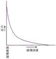
图3中,化学增强玻璃200自表面210起在深度方向具有折射率分布。图3中,若将距离表面210的深度设为x、将深度方向的折射率分布设为n(x),则深度方向的折射率分布n(x)例如成为如图4所示的曲线。即,化学增强玻璃200中,通过化学增强等,表面210的折射率高,随着变深而变低,在表面层结束的深度(由离子交换带来的折射率变化消失的深度)变为与原来的玻璃的折射率相同,在比其深的部分变为恒定(原来的玻璃的折射率)。In FIG. 3 , the chemically strengthened
这样,在化学增强玻璃200的表面层中,随着向内部方向前进,折射率变低。因此,在图3中,相对于表面210以浅的角度入射的光线L(在图3的例子中,借助具有比化学增强玻璃200大的折射率的光供给构件20而入射)、光线轨迹逐渐与表面210接近平行,在最深点xt处自深度方向向表面210的方向反转。然后,光线轨迹反转了的光线以与从入射的点到反转的点的光线轨迹的形状相似的形状朝向表面210,在表面210至少一部分发生反射,并再次向化学增强玻璃200的内部前进。In this way, in the surface layer of the chemically strengthened
再次前进到化学增强玻璃200的内部的光线通过与至此为止的光线轨迹相同形状的轨迹,在深度xt处反转并返回至表面210,重复此行为,光线在表面210与最深点xt之间往复前进。而且,由于光在距离表面210为宽度xt的限定空间中行进,因此光可以仅以有限值的离散的模式的形式传播。The ray that proceeds to the interior of the chemically strengthened
即,仅有多个一定的规定路径的光线能够在化学增强玻璃200的表面层传播。该现象称为光波导效果,也是光线在光纤内前进的原理。通过光波导效果在表面210传播的光的模式、及该模式的光线轨迹由自表面210起在深度方向的折射率分布决定。That is, only a plurality of certain predetermined paths of light can propagate through the surface layer of the chemically strengthened
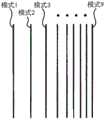
图5为说明存在多个模式时各模式的光线轨迹的图。图5的例子中示出了模式1、模式2、及模式3这3个模式,但这是为了简化说明,有时根据化学增强玻璃而具有更高次的模式。对于次数最低的模式1,光线轨迹在表面210反射时与表面210的角度最浅(出射余角最小)。另外,每个模式光线轨迹的最深点不同,模式1的最深点xt1最浅。随着模式的次数变大,在表面210反射时与表面210所成的角度变大(出射余角变大)。另外,模式2的最深点xt2比模式1的最深点xt1深,模式3的最深点xt3比模式2的最深点xt2进一步更深。FIG. 5 is a diagram illustrating the ray locus of each mode when there are multiple modes. In the example of FIG. 5 , three modes of
此处,光线相对于规定面的入射角为入射的光线与规定面的法线所成的角。与此相对,光线相对于规定面的入射余角为入射的光线与规定面所成的角。即,如果光线相对于规定面的入射角为θ,则光线相对于规定面的入射余角为π/2-θ。另外,关于光线相对于规定面的出射角与出射余角的关系,也是同样的。Here, the incident angle of the light ray with respect to the predetermined surface is the angle formed by the incident light ray and the normal line of the predetermined surface. On the other hand, the complementary angle of incidence of the light ray with respect to the predetermined surface is the angle formed by the incident light ray and the predetermined surface. That is, if the incident angle of the light ray with respect to the predetermined surface is θ, the incident complementary angle of the light ray with respect to the predetermined surface is π/2-θ. In addition, the same applies to the relationship between the exit angle of the light beam with respect to the predetermined surface and the exit angle.
需要说明的是,图5中用1条光线表示入射光,但入射光具有一定的宽度。具有该宽度的光各自在相同模式下从表面210出射的光的余角也相同。而且,由于产生的模式以外的光相互抵消,因此除了与各模式对应的光以外不从表面210出射。It should be noted that in FIG. 5 , the incident light is represented by one ray, but the incident light has a certain width. Lights having this width each have the same complementary angle of light exiting the
另外,在图2中,光供给构件20、光取出构件30、及化学增强玻璃200在深度方向为相同形状。因此,对于由光转换构件40集光的光,在作为光转换构件40的焦点面的摄像元件60上,与其模式对应的光在深度方向成为亮线而成像。In addition, in FIG. 2, the
而且,由于每个模式下出射余角不同,因此如图6所示,亮线按照每个模式依次排列而成为亮线列。需要说明的是,亮线列通常形成明线的列,但在图2中的光供给构件20与光取出构件30接触而成为一体的情况下,也有相对于出射光,来自光源的直接光作为参照光而起作用,形成暗线的列的情况。但是,无论是形成明线的列的情况、还是形成暗线的列的情况,各线的位置均完全相同。Furthermore, since the exit angle is different for each mode, as shown in FIG. 6 , the bright lines are sequentially arranged for each mode to form a bright line row. It should be noted that the row of bright lines usually forms the row of bright lines. However, in the case where the
这样,亮线在模式成立时以明线或暗线显现。即使是在亮线的干涉色根据参照光的明暗而变化的情况下,也完全不影响本实施方式的折射率分布、应力分布的计算。于是,本申请中,无论是明线还是暗线,为了方便起见,均表达为亮线。In this way, bright lines appear as bright or dark lines when the mode is established. Even if the interference color of the bright line changes depending on the brightness of the reference light, the calculation of the refractive index distribution and the stress distribution in the present embodiment is not affected at all. Therefore, in this application, whether it is a bright line or a dark line, for the sake of convenience, it is expressed as a bright line.
另外,在表面层内传播的光线发生折射而出射到化学增强玻璃200外时的出射余角与使具有该光线在表面层内的光线轨迹的最深点的化学增强玻璃200的折射率、即等效折射率nn相等的折射率的介质接触光取出构件30时的临界折射光的出射余角相等。在各模式下的最深点也可以解释为在该模式下的光线发生全反射的点。In addition, when the light propagating in the surface layer is refracted and exits the chemically strengthened
此处,对于某模式间的等效折射率nn之差Δn与亮线间的距离ΔS的关系,若采用光转换构件40的焦点距离f、光取出构件30的折射率np、化学增强玻璃200的折射率ng,则有下述式(8)及式(9)的关系。Here, for the relationship between the difference Δn of the equivalent refractive index nn between a certain mode and the distance ΔS between the bright lines, if the focal distance f of the
Δn=k1·ΔS (8)Δn=k1 ·ΔS (8)

因此,如果知道作为摄像元件60上的一点的等效折射率的位置,则可以根据观测到的亮线的位置,求出与该亮线对应的各模式的等效折射率、即在化学增强玻璃200的表面层内的光线轨迹的最深点的折射率。Therefore, if the position of the equivalent refractive index as a point on the
(折射率分布的算出)(Calculation of refractive index distribution)
用下述式(10)算出折射率分布。此处,为了获得任意折射率分布下的模式的成立条件,将折射率分布设为任意分布n(x)。The refractive index distribution was calculated by the following formula (10). Here, in order to obtain the establishment condition of the mode in an arbitrary refractive index distribution, the refractive index distribution is assumed to be an arbitrary distribution n(x).
式(10)中,θ为以直线前进微小的距离dr的光线的出射余角,n0为化学增强玻璃表面的折射率,Θ为入射至化学增强玻璃的光线的出射余角,λ为入射至化学增强玻璃的光线的波长,N为模式的次数(例如,为模式1时N=1)。另外,G1为光线入射至化学增强玻璃的点,F2为光线反转的最深点(xt),G2为在F2反转的光线再次到达至化学增强玻璃的点,每个模式下不同。需要说明的是,左边的第1项为在表面层内传播的光相关的项,左边的第2项为在表面210传播的光相关的项。In formula (10), θ is the outgoing complementary angle of the light traveling a small distance dr in a straight line, n0 is the refractive index of the surface of the chemically strengthened glass, Θ is the outgoing complementary angle of the light incident on the chemically strengthened glass, and λ is the incident angle. The wavelength of light to the chemically strengthened glass, where N is the number of modes (eg, N=1 for mode 1). In addition, G1 is the point where the light enters the chemically strengthened glass, F2 is the deepest point (xt) where the light is inverted, and G2 is the point where the light inverted at F2 reaches the chemically strengthened glass again, and it is different for each mode. It should be noted that the first item on the left is an item related to light propagating in the surface layer, and the second item on the left is an item related to light propagating on the

用式(10),假设在次数相邻的模式的最深点之间化学增强玻璃200的折射率变化率为恒定,从次数最低的模式起依次计算各个模式的最深点的深度,求出整体的折射率分布。Using Equation (10), assuming that the rate of change of the refractive index of the chemically strengthened
例如,在图5中,将在各模式的最深部xt1、xt2、xt3···的深度处的表面层的折射率即等效折射率设为n1、n2、n3···。另外,将表面210-xt1之间、xt1-xt2之间、xt2-xt3之间、···的折射率变化率设为直线,将其折射率变化率设为α1、α2、α3···。For example, in FIG. 5 , the refractive indices of the surface layers at the depths of the deepest partsxt1 ,xt2 ,xt3 . In addition, let the refractive index change rates between the surfaces 210-xt1, xt1-xt2, xt2-xt3, ... be straight lines, and the refractive index change rates be α1, α2, α3, ... .
首先,使用通过距表面210最近的部分的模式1、2,求出α1、α2、及xt1、xt2。模式3中,xt1、xt2为已知,不明确的参数只有xt3,因此基于这些求出xt3。同样地,求出模式4、5···和依次求出xt4、xt5···,求出与全部模式对应的最深点的xtn。然后,求出自表面210起深度方向的折射率分布。First, α1 , α2 , and xt1 , xt2 are obtained using
图7为呈现玻璃内部的光线轨迹的图。参照图7,对计算折射率分布的具体方法进行说明。首先,使用光线追踪法,求出式(10)的左边。在图7中,x方向(纵向)为化学增强玻璃200的深度方向,y方向(横方向)为与化学增强玻璃200的表面210水平的方向。另外,在深度x的折射率为n(x)。需要说明的是,H为表面210的法线。FIG. 7 is a diagram showing light trajectories inside the glass. A specific method of calculating the refractive index distribution will be described with reference to FIG. 7 . First, the left side of Equation (10) is obtained by using the ray tracing method. In FIG. 7 , the x direction (longitudinal direction) is the depth direction of the chemically strengthened
此处,将光供给构件20的折射率设为1.72,来考虑从光供给构件20以入射余角Ψ入射至表面210的光线L。另外,将入射点的坐标设为(x0、y0)。需要说明的是,x0=0。此时,入射至化学增强玻璃200的内部的光线L以出射余角θ1进行折射前进。此时,对于Ψ和θ1,斯涅耳(Snell)式成立。Here, let the refractive index of the
接着,在化学增强玻璃200的内部,虽然光线L的轨迹为曲线,但假设某一微小的距离dr是以直线前进(距离dr理想的是波长的1/10~1/100左右)。即,光线在出射余角θ1的方向仅有dr以直线前进。此时,x方向的移动量dx1=dr·sinθ1、y方向的移动量dy1=dr·cosθ1。另外,移动的点的坐标(x1、y1)=(dr·sinθ1、y0+dr·cosθ1)。Next, inside the chemically strengthened
在该部分光线轨迹的起点的坐标(x0=0、y0)处的折射率为n(0)、在终点的坐标(x1、y1)的折射率为n(x1),但设定在该光线轨迹内起点的折射率为恒定,在终点折射率变为n(x1)。这样,接下来的光线轨迹遵循斯涅耳定律,角度改变为出射余角θ2并前进。以出射余角θ2前进的光仅有dr以直线前进,进而向出射余角θ3(未图示)改变方向而前进。重复此行为,追踪光线轨迹,求出整体的光线轨迹。The refractive index at the coordinates (x0=0, y0) of the starting point of this part of the ray trace is n(0), and the refractive index at the coordinates (x1, y1) of the end point is n(x1), but set at the ray The index of refraction at the start point in the track is constant, and the index of refraction at the end point becomes n(x1). In this way, the following ray trace follows Snell's law, the angle changes to the exit complementary angle θ2 and proceeds. The light traveling at the complementary exit angle θ2 travels in a straight line only by dr, and further changes its direction toward the complementary exit angle θ3 (not shown) and proceeds. Repeat this behavior to trace the ray trace to find the overall ray trace.
此时,每前进dr,计算出式(10)的左边的第1项。例如,在坐标(x0=0、y0)~坐标(x1、y1)的部分,第1项计算为dr·cosθ1·n(0)。关于其它的dr也同样地进行计算。而且,将在每个dr求出的第1项相加直到光线轨迹返回至表面210为止时,式(10)的左边第1项全部求出。另外,此时,已知该光线轨迹在y方向前进的距离Σdy。根据式(10)中dG1G2=Σdy、Θ=θ1,求出式(8)的左边第2项,式(10)的左边全部求出。At this time, the first term on the left side of Equation (10) is calculated every time dr is advanced. For example, in the part from coordinates (x0=0, y0) to coordinates (x1, y1), the first term is calculated as dr·cosθ1·n(0). The other drs are also calculated in the same way. Then, when the first terms obtained for each dr are added until the ray trace returns to the
接着,对计算折射率分布的方法进行说明。首先,如Yogyo-Kyokai-Shi(窯業協会誌)87{3}1979中也示出的,根据模式1和模式2的亮线的位置,求出表面210的折射率和模式2的最深点。由此,可知3个点即表面210(x=0)、模式1的最深点(xt1)、模式2的最深点(xt2)的值与其点的折射率n0、n1、n2。但是,由于表面为模式1和模式2的外推,因此该3点为直线。Next, a method of calculating the refractive index distribution will be described. First, as also shown in Yogyo-Kyokai-Shi (Records of the Kiln Industry Association) 87{3}1979, the refractive index of the
接着,假定在模式3下的最深点xt3为适当的值,对至xt3为止的折射率分布进行定义。然后,通过上述计算方法,计算该分布中的式(10)的左边。右边由模式的次数来决定,在模式3下为2.75λ。Next, assuming that the deepest point xt3 in Mode 3 is an appropriate value, the refractive index distribution up to xt3 is defined. Then, the left side of the equation (10) in the distribution is calculated by the above calculation method. The right side is determined by the number of modes, which is 2.75λ in mode 3.
然后,将xt3作为参数,使用二分法、牛顿法等非线性方程式的计算方法,由此求出xt3。而且,求出xt3后,根据接下来的模式4的亮线位置,求出xt4,对全部的亮线重复同样的计算,由此算出整体的折射率分布。Then, xt3 is calculated|required using the calculation method of a nonlinear equation, such as a bisection method and Newton's method, using xt3 as a parameter. Then, after xt3 is obtained, xt4 is obtained from the position of the bright line in the next mode 4, and the same calculation is repeated for all the bright lines, thereby calculating the overall refractive index distribution.
(应力分布的算出)(Calculation of stress distribution)
基于P偏光与S偏光的折射率分布之差和化学增强玻璃200的光弹性常数,算出自化学增强玻璃200的表面210起深度方向的应力分布σ(x)。具体而言,使用下述式(11),算出应力分布。式(11)中,kc为光弹性常数,ΔnPS(x)为P偏光与S偏光的折射率分布的差。由于P偏光的折射率分布nP(x)和S偏光的折射率分布nS(x)各自是离散地得到的,因此用各个点算出应力分布σ(x)。The stress distribution σ(x) in the depth direction from the
σ(x)=ΔnPS(x)/kc (11)σ(x)=ΔnPS (x)/kc (11)
P偏光的折射率分布nP(x)和S偏光的折射率分布nS(x)具体而言分别以np(xi)、ns(xk)的形式获得。这是指通过上述得到的各个折射率分布是离散的,i和k各自为整数。对于P偏光和S偏光,亮线的位置不同,因此即使i=k=1,也未必xi=xk。因此,对于x处的折射率,对距离x最近的2点xi、xi+1,对折射率nP(xi)和nP(xi+1)、以及nS(xk)和ns(xk+1)进行线性差值而获得。由此,关于任意的x,可以得到P偏光的折射率分布nP(x)和S偏光的折射率分布nS(x)。Specifically, the refractive index distribution nP (x) of the P-polarized light and the refractive index distribution nS (x) of the S-polarized light are obtained as np (xi ) andns (xk ), respectively. This means that the respective refractive index distributions obtained by the above are discrete, and i and k are each an integer. Since the positions of the bright lines are different for P-polarized light and S-polarized light, even if i=k=1, it is not necessarily that xi =xk . Therefore, for the index of refraction at x, for the 2 points xi , xi+1 closest to x, for the indices of refraction nP (xi ) and nP (xi+1 ), and nS (xk ) andns (xk+1 ) are obtained by linear difference. Thus, with respect to any x, the refractive index distribution nP (x) of the P-polarized light and the refractive index distribution nS (x) of the S-polarized light can be obtained.
根据以1μm步长计算x而得到的nP(xm)、nS(xm)的差,导出ΔnPS(xm)。另外,将ΔnPS(xm)应用于式(11),由此获得σ(xm)。此处,m为整数。用二个误差函数通过最小二乘法对x以1μm步长得到的应力分布σ(xm)进行近似,由此得到连续的应力分布函数即σ(x)。需要说明的是,近似地得到的应力分布σ(x)中,应力变为0的点是DOL值。ΔnPS (xm ) is derived from the difference between nP (xm ) and nS (xm ) obtained by calculating x in 1 μm steps. In addition, ΔnPS (xm ) is applied to equation (11), thereby obtaining σ(xm ). Here, m is an integer. The stress distribution σ(xm ) obtained by x with a step size of 1 μm is approximated by the least square method with two error functions, thereby obtaining a continuous stress distribution function σ(x). In the approximately obtained stress distribution σ(x), the point at which the stress becomes 0 is the DOL value.
但是,关于CT值,由于是由P偏光与S偏光的微小的折射率差求出的,因此尤其在折射率的变化小的部分(折射率分布的倾斜变缓慢的零交叉附近),P偏光与S偏光的折射率差变小,测定误差变大。因此,以将算出的压缩应力层的应力分布在化学增强玻璃200的深度方向进行积分而得到的值与化学增强玻璃200的内部的拉伸应力平衡的方式,使用式(5)算出CT值(CT5值)。此处,σ(x)为通过式(11)求出的应力分布函数,相当于图7中所示的化学增强玻璃200的深度方向的位置x处的压缩应力值。将积分范围设为从化学增强玻璃200的表面210到中央,以积分结果为零的方式来确定CT5值。However, since the CT value is obtained from the slight difference in refractive index between the P-polarized light and the S-polarized light, the P-polarized light is particularly weak in the portion where the change in the refractive index is small (in the vicinity of the zero crossing where the gradient of the refractive index distribution becomes slow). The difference in refractive index with S-polarized light becomes smaller, and the measurement error becomes larger. Therefore, the CT value ( CT5 value). Here, σ(x) is the stress distribution function obtained by the formula (11), and corresponds to the compressive stress value at the position x in the depth direction of the chemically strengthened
(测定的流程)(measurement flow)
图8为例示出本实施方式的测定方法的流程图。首先,在步骤S501中,使来自光源10的光向化学增强玻璃200的表面层内入射(光供给工序)。接着,在步骤S502中,使在化学增强玻璃200的表面层内传播的光向化学增强玻璃200外出射(光取出工序)。FIG. 8 is a flowchart illustrating the measurement method of the present embodiment. First, in step S501, light from the
接着,在步骤S503中,光转换构件40及偏光构件50将出射的光的、相对于出射面平行及垂直振动的二种光成分(P偏光和S偏光)各自转换为具有至少3条以上的亮线的二种亮线列(光转换工序)。Next, in step S503, the
接着,在步骤S504中,摄像元件60对通过光转换工序而转换的二种亮线列进行摄像(摄像工序)。接着,在步骤S505中,演算部70的位置测定单元71根据摄像工序中得到的图像,测定二种亮线列的各亮线的位置(位置测定工序)。Next, in step S504, the
接着,在步骤S506中,演算部70的折射率分布算出单元72根据二种亮线列的各自至少3条以上的亮线的位置算出与二种光成分对应的自化学增强玻璃200的表面210起深度方向的折射率分布(折射率分布算出工序)。Next, in step S506, the refractive index distribution calculating unit 72 of the calculating
接着,在步骤S507中,演算部70的应力分布算出单元73基于二种光成分的折射率分布之差和玻璃的光弹性常数算出自化学增强玻璃200的表面210起深度方向的应力分布(应力分布算出工序)。Next, in step S507 , the stress distribution calculation unit 73 of the
利用以上的测定装置及测定方法,根据二种亮线列的各自至少3条以上的亮线的位置,算出与二种光成分对应的自化学增强玻璃的表面起深度方向的折射率分布。然后,基于二种光成分的折射率分布之差和玻璃的光弹性常数,算出自化学增强玻璃的表面起深度方向的应力分布。Using the above-mentioned measuring apparatus and measuring method, the refractive index distribution in the depth direction from the surface of the chemically strengthened glass corresponding to the two light components was calculated from the positions of at least three or more bright lines in each of the two bright line arrays. Then, based on the difference between the refractive index distributions of the two light components and the photoelastic constant of the glass, the stress distribution in the depth direction from the surface of the chemically strengthened glass is calculated.
本实施方式的化学增强玻璃的用途没有特别限定。由于具有高的机械强度,因此适合用于在预想到由落下导致的冲击、与其它物质接触的部位。The application of the chemically strengthened glass of the present embodiment is not particularly limited. Due to its high mechanical strength, it is suitable for use in places where impact due to falling and contact with other substances are expected.
[实施例][Example]
示出与本实施方式的化学增强玻璃对应的实施例。Examples corresponding to the chemically strengthened glass of the present embodiment are shown.
<评价方法><Evaluation method>
本实施例中的各种评价通过以下所示的分析方法进行。Various evaluations in this Example were performed by the analysis method shown below.
(玻璃的评价:表面应力)(Evaluation of glass: surface stress)
本实施例的化学增强玻璃的应力分布通过前述的实施方式中记载的方法来算出。具体而言,基于对P偏光和S偏光各自算出的整体的折射率分布,通过前述的(应力分布的算出)的项中说明的计算方法来算出应力分布。The stress distribution of the chemically strengthened glass of the present Example was calculated by the method described in the aforementioned embodiment. Specifically, the stress distribution is calculated based on the overall refractive index distribution calculated for each of the P-polarized light and the S-polarized light by the calculation method described in the section (Calculation of Stress Distribution).
此处,该应力分布中,将距离最表面的玻璃深度为0μm处的应力值(单位为MPa)设为本实施例的化学增强玻璃的压缩应力层的表面压缩应力值(CS)。另外,将在玻璃内部应力值为0MPa的玻璃深度的最小值(单位为μm)设为压缩应力层的深度(DOL)。进而,由该应力分布求出应力值为CS值的半值的位置(HW、单位为μm)。Here, in this stress distribution, the stress value (in MPa) at a depth of 0 μm from the outermost glass is set as the surface compressive stress value (CS) of the compressive stress layer of the chemically strengthened glass of this example. In addition, let the minimum value (unit is micrometer) of the glass depth in which the stress value in glass is 0 MPa be the depth (DOL) of a compressive stress layer. Furthermore, from this stress distribution, the position (HW, unit is μm) where the stress value is the half value of the CS value is obtained.
(化学增强玻璃的评价:破裂行为)(Evaluation of chemically strengthened glass: cracking behavior)
如下地评价化学增强玻璃的破裂行为。图9中利用概略图示出评价方法。首先,对压头110以其前端部111相对于化学增强玻璃200的表面210垂直的方式在静态载荷条件下进行按压。安装有压头110的维氏硬度试验机100使用FUTURE-TECH CORP.制FLS-ARS9000。压头110使用前端部111的对面角度为60°的压头,并向化学增强玻璃200的表面210以60μm/秒的速度、以对压头110施加4kgf(≈39.2N)的载荷的方式进行按压,在达到该载荷的状态下保持15秒钟,其后对压头进行卸载,观察60秒后的化学增强玻璃200。由此测量碎裂的化学增强玻璃200的破片数量(破碎数),评价化学增强玻璃200的破裂行为。The fracture behavior of the chemically strengthened glass was evaluated as follows. FIG. 9 shows the evaluation method using a schematic diagram. First, the
<例1~4><Examples 1 to 4>
(第1化学增强工序)(1st chemical enhancement step)
在SUS制的杯中加入硝酸钾(KNO3)和硝酸钠(NaNO3),以使其合计量为4000g、并且KNO3的浓度(质量%)分别如表1的第1化学增强工序的项所示,用覆套式电阻加热器加热至规定的温度,制备硝酸钾和硝酸钠的混合熔融盐。此处,将50mm×50mm×400μm的铝硅酸盐玻璃预热至350℃后,在熔融盐中浸渍规定的时间、进行离子交换处理后,冷却至室温附近,由此进行第1化学增强处理。第1化学增强处理的条件如表1所记载。对得到的化学增强玻璃进行水洗,供于下一工序。Potassium nitrate (KNO3 ) and sodium nitrate (NaNO3 ) were added to a cup made of SUS so that the total amount was 4000 g, and the KNO3 concentrations (mass %) were as listed in the first chemical enhancement step in Table 1, respectively. As shown, the mixed molten salt of potassium nitrate and sodium nitrate was prepared by heating to a predetermined temperature with a mantle type resistance heater. Here, the aluminosilicate glass of 50 mm×50 mm×400 μm was preheated to 350° C., immersed in molten salt for a predetermined time, subjected to ion exchange treatment, and then cooled to around room temperature, thereby performing the first chemical strengthening treatment . The conditions of the first chemical enhancement treatment are as described in Table 1. The obtained chemically strengthened glass is washed with water and used for the next step.
铝硅酸盐玻璃(比重:2.41)组成(摩尔%表示):SiO2 68%、Al2O3 10%、Na2O14%、MgO 8%Aluminosilicate glass (specific gravity: 2.41) composition (in mol%): SiO2 68%, Al2 O3 10%, Na2 O 14%,
(第2化学增强工序)(2nd chemical enhancement step)
在SUS制的杯中加入硝酸钾(KNO3)和硝酸钠(NaNO3)以使其合计量为4000g、并且KNO3的浓度(质量%)分别如表1的第2化学增强工序的项所示,用覆套式电阻加热器加热至规定的温度,制备硝酸钾和硝酸钠的混合熔融盐、或100%质量%的硝酸钾熔融盐。此处,将供于第1化学增强工序的玻璃预热至350℃后,在熔融盐中浸渍规定的时间,进行离子交换处理后,冷却至室温附近,由此进行第2化学增强处理。第2化学增强处理的条件如表1所记载。对得到的化学增强玻璃用纯水清洗多次后,通过鼓风进行干燥。通过以上,得到例1~4的化学增强玻璃。Potassium nitrate (KNO3 ) and sodium nitrate (NaNO3 ) were added to a cup made of SUS so that the total amount was 4000 g, and the concentrations (mass %) of KNO3 were as shown in the items of the second chemical enhancement step in Table 1, respectively. As shown, a mantle type resistance heater was used to heat to a predetermined temperature to prepare a mixed molten salt of potassium nitrate and sodium nitrate, or a 100% mass % potassium nitrate molten salt. Here, the second chemical strengthening treatment is performed by preheating the glass used in the first chemical strengthening step to 350° C., immersing it in molten salt for a predetermined time, performing ion exchange treatment, and then cooling to around room temperature. The conditions of the second chemical enhancement treatment are as described in Table 1. The obtained chemically strengthened glass was washed with pure water several times, and then dried by blowing air. Through the above, the chemically strengthened glasses of Examples 1 to 4 were obtained.
<例5~8><Examples 5 to 8>
使用50mm×50mm×550μm的铝硅酸盐玻璃,除此以外,与例1同样地,得到例5~8的化学增强玻璃。第1、第2化学增强处理的条件如表1所记载。Chemically strengthened glasses of Examples 5 to 8 were obtained in the same manner as in Example 1, except that aluminosilicate glass of 50 mm×50 mm×550 μm was used. The conditions of the first and second chemical enhancement treatments are as described in Table 1.
<例9~10><Examples 9 to 10>
使用50mm×50mm×800μm的铝硅酸盐玻璃,除此以外,与例1同样地,得到例9、10的化学增强玻璃。第1、第2化学增强处理的条件如表1所记载。Chemically strengthened glasses of Examples 9 and 10 were obtained in the same manner as in Example 1, except that aluminosilicate glass of 50 mm×50 mm×800 μm was used. The conditions of the first and second chemical enhancement treatments are as described in Table 1.
<例11~15><Examples 11 to 15>
使用50mm×50mm×1000μm的铝硅酸盐玻璃,除此以外,与例1同样地,得到例11~15的化学增强玻璃。第1、第2化学增强处理的条件如表1所记载。Chemically strengthened glasses of Examples 11 to 15 were obtained in the same manner as in Example 1, except that aluminosilicate glass of 50 mm×50 mm×1000 μm was used. The conditions of the first and second chemical enhancement treatments are as described in Table 1.
<例16~18><Examples 16 to 18>
(第1化学增强工序)(1st chemical enhancement step)
在SUS制的杯中加入硝酸钾(KNO3)和硝酸钠(NaNO3),以使其合计量为4000g、并且KNO3的浓度(质量%)分别如表1的第1化学增强工序的项所示,用覆套式电阻加热器加热至规定的温度,制备硝酸钾和硝酸钠的混合熔融盐、或100%质量%的硝酸钾熔融盐。此处,将50mm×50mm×500μm的铝硅酸盐玻璃预热至350℃后,在熔融盐中浸渍规定的时间,进行离子交换处理后,冷却至室温附近,由此进行第1化学增强处理。第1化学增强处理的条件如表1所记载。对得到的化学增强玻璃用纯水清洗多次后,通过鼓风进行干燥,不供于第2化学增强工序,得到例16~18的化学增强玻璃。Potassium nitrate (KNO3 ) and sodium nitrate (NaNO3 ) were added to a cup made of SUS so that the total amount was 4000 g, and the KNO3 concentrations (mass %) were as listed in the first chemical enhancement step in Table 1, respectively. As shown, a mantle type resistance heater was used to heat to a predetermined temperature to prepare a mixed molten salt of potassium nitrate and sodium nitrate, or a 100% by mass molten salt of potassium nitrate. Here, the aluminosilicate glass of 50 mm × 50 mm × 500 μm was preheated to 350° C., immersed in molten salt for a predetermined period of time, subjected to ion exchange treatment, and then cooled to around room temperature to perform the first chemical strengthening treatment. . The conditions of the first chemical enhancement treatment are as described in Table 1. After the obtained chemically strengthened glass was washed with pure water several times, it was dried by blowing air, and the chemically strengthened glass of Examples 16 to 18 was obtained without being used in the second chemically strengthened step.
铝硅酸盐玻璃(比重:2.41)组成(摩尔%表示):SiO2 68%、Al2O3 10%、Na2O14%、MgO 8%Aluminosilicate glass (specific gravity: 2.41) composition (in mol%): SiO2 68%, Al2 O3 10%, Na2 O 14%,
<例19~21><Examples 19 to 21>
使用50mm×50mm×800μm的铝硅酸盐玻璃,除此以外,与例16同样地,得到例19~21的化学增强玻璃。第1化学增强处理的条件如表1所记载。Chemically strengthened glasses of Examples 19 to 21 were obtained in the same manner as in Example 16, except that aluminosilicate glass of 50 mm×50 mm×800 μm was used. The conditions of the first chemical enhancement treatment are as described in Table 1.
<例22~24><Examples 22 to 24>
使用50mm×50mm×1000μm的铝硅酸盐玻璃,除此以外,与例16同样地,得到例22~24的化学增强玻璃。第1化学增强处理的条件如表1所记载。Chemically strengthened glasses of Examples 22 to 24 were obtained in the same manner as in Example 16, except that aluminosilicate glass of 50 mm×50 mm×1000 μm was used. The conditions of the first chemical enhancement treatment are as described in Table 1.
<例25><Example 25>
使用50mm×50mm×800μm的铝硅酸盐玻璃,除此以外,与例1同样地,得到例25的化学增强玻璃。第1、第2化学增强处理的条件如表1所记载。The chemically strengthened glass of Example 25 was obtained in the same manner as in Example 1, except that aluminosilicate glass of 50 mm×50 mm×800 μm was used. The conditions of the first and second chemical enhancement treatments are as described in Table 1.
[表1][Table 1]
表1Table 1

对这样得到的化学增强玻璃进行各种评价。另外,根据由此求出的CS值、DOL值、及板厚t(单位:μm),求出基于式(1)的CT值(CT1值)。另外,根据该应力分布和式(5),求出基于式(5)的CT值(CT5值)。CTlimit值是根据板厚t(单位:μm)以CTlimit=-38.7×ln(t/1000)+48.2[MPa]的形式求出的。将结果示于表2。Various evaluations were performed on the chemically strengthened glass thus obtained. In addition, from the CS value, DOL value, and plate thickness t (unit: μm) thus obtained, the CT value (CT1 value) based on the formula (1) is obtained. In addition, from this stress distribution and equation (5), a CT value (CT5 value) based on equation (5) is obtained. The CTlimit value was obtained from the sheet thickness t (unit: μm) in the form of CTlimit =−38.7×ln(t/1000)+48.2 [MPa]. The results are shown in Table 2.
[表2][Table 2]
表2Table 2

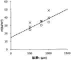
另外,对表2的各试样,对板厚与CT5值的关系进行制图。另外,也示出相当于CTlimit值的曲线。对例1~15、及例25的试样的制图示于图10,对例16~24的试样的制图示于图11。需要说明的是,在图10、11中,将破坏时破碎数不足15个的试样用○标示,将为15个以上的试样用×标示。In addition, for each sample in Table 2, the relationship between the plate thickness and the CT5 value was plotted. In addition, a curve corresponding to the CTlimit value is also shown. The graphs of the samples of Examples 1 to 15 and 25 are shown in FIG. 10 , and the graphs of the samples of Examples 16 to 24 are shown in FIG. 11 . In addition, in FIGS. 10 and 11 , the samples with less than 15 pieces broken at the time of failure are marked with ○, and the samples with 15 or more pieces are marked with ×.
根据图11的结果,如例16~24那样,对于仅进行了一次化学增强工序的那样的、具有可接受三角形近似的应力曲线的化学增强玻璃,CT5值超过了CTlimit值的玻璃在破坏时破碎数变多。因此,可以说对于具有可接受三角形近似的应力曲线的化学增强玻璃,玻璃破裂时开始细碎地飞散的CT5值(上限)能够近似于CTlimit值。According to the results of FIG. 11 , as in Examples 16 to 24, for the chemically strengthened glass having a stress curve with an acceptable triangular approximation, as in Examples 16 to 24, the glass whose CT5 value exceeds the CTlimit value is broken. The number of broken pieces increases. Therefore, it can be said that the CT5 value (upper limit) at which the glass starts to scatter finely when the glass is broken can be approximated to the CTlimit value for a chemically strengthened glass having a stress curve with an acceptable triangular approximation.
根据图10的结果可知,即使为CT5值超过了CTlimit值的玻璃,有时破坏时的破碎数也少。因此,对于具有三角形近似不可接受的应力曲线的化学增强玻璃,玻璃破裂时开始细碎地飞散的CT5值(上限)与以往认为的上限的CTlimit值大大不同。这是在以往那样的具有三角形近似相对可接受的所谓互补误差函数曲线的化学增强玻璃中未观察到的现象。From the results of FIG. 10 , even if it is glass whose CT5 value exceeds the CTlimit value, the number of fractures at the time of fracture may be small. Therefore, for chemically strengthened glass having an unacceptably triangular approximation stress curve, the CT5 value (upper limit) at which the glass begins to scatter finely when broken is greatly different from the CTlimit value of the upper limit which has been conventionally considered. This is a phenomenon not observed in conventional chemically strengthened glasses having a so-called complementary error function curve with a relatively acceptable triangular approximation.
另外可知,通过使成为表面应力值(CS值)的半值(HW)的位置不足8μm(例25),能够达成大的CS值和深的DOL值,并且玻璃破裂时不易细碎地飞散。In addition, it was found that by making the position of the half value (HW) of the surface stress value (CS value) less than 8 μm (Example 25), a large CS value and a deep DOL value can be achieved, and the glass is not easily scattered when broken.
关于具有不可接受三角形近似的应力曲线的化学增强玻璃,也为了能够管理化学增强玻璃的破裂行为而对例1~24的化学增强玻璃研究了内部rE值。此处,化学增强玻璃的内部能量密度rE由前述的式(6)来定义。将结果示于表3。Regarding chemically strengthened glasses having stress curves with unacceptable triangular approximations, the chemically strengthened glasses of Examples 1 to 24 were also investigated for internal rE values in order to be able to manage the cracking behavior of the chemically strengthened glasses. Here, the internal energy density rE of the chemically strengthened glass is defined by the aforementioned formula (6). The results are shown in Table 3.
[表3][table 3]
表3table 3

另外,对表3的各试样,在图12、13中分别对例1~25的化学增强玻璃,对内部能量密度rE的值进行制图。对例1~15及例25的试样的制图示于图12,对例16~24的试样的制图示于图13。需要说明的是,在图12、13中,也与图10、11同样地,将破坏时破碎数不足15个的试样用○标示,将为15个以上的试样用×标示。In addition, about each sample of Table 3, the value of the internal energy density rE was plotted with respect to the chemically strengthened glass of Examples 1-25 in FIGS. 12 and 13, respectively. The graphs of the samples of Examples 1 to 15 and 25 are shown in FIG. 12 , and the graphs of the samples of Examples 16 to 24 are shown in FIG. 13 . In addition, in FIGS. 12 and 13 , similarly to FIGS. 10 and 11 , the samples with less than 15 pieces broken at the time of failure are marked with ○, and the samples with 15 or more pieces are marked with ×.
根据图12、13的结果可知,化学增强玻璃的内部能量密度rE超过一定临界值时,破坏时破碎数变多。可以以直线连结处于该临界值的数值,如图12、13所示,任意板厚的函数中,具有超过23.3×t/1000+15〔kJ/m2〕的内部能量密度的化学增强玻璃中,破碎数变多。因此,本说明书中将内部能量密度rE的上限值定义为rElimit=23.3×t/1000+15〔kJ/m2〕。对于内部能量密度rE满足前述式(7)的情况,玻璃破裂时不易细碎地飞散,因此优选。该条件是本申请的发明人等深入研究后结果发现的、化学增强玻璃的内部能量密度rE值的上限值。对于该上限值,根据图12可知,即使是不具有所谓互补误差函数曲线的化学增强玻璃也可适用。From the results of FIGS. 12 and 13 , it can be seen that when the internal energy density rE of the chemically strengthened glass exceeds a certain critical value, the number of fractures at the time of failure increases. Values at this critical value can be connected by a straight line. As shown in Figs. 12 and 13, in a chemically strengthened glass having an internal energy density exceeding 23.3×t/1000+15[kJ/m2 ] as a function of any plate thickness , the number of broken pieces increases. Therefore, in this specification, the upper limit of the internal energy density rE is defined as rElimit =23.3×t/1000+15[kJ/m2 ]. When the internal energy density rE satisfies the above-mentioned formula (7), it is preferable that the glass is not easily scattered when broken. This condition is the upper limit value of the internal energy density rE value of the chemically strengthened glass, which was found by the inventors of the present application as a result of intensive research. Regarding this upper limit value, it can be seen from FIG. 12 that it is applicable even to chemically strengthened glass which does not have a so-called complementary error function curve.
根据该结果,无论是具有怎样的应力曲线的化学增强玻璃,通过将内部能量密度rE控制为满足式(7)的数值范围内,均能够管理化学增强玻璃的破裂行为。From this result, regardless of the stress profile of the chemically strengthened glass, the cracking behavior of the chemically strengthened glass can be managed by controlling the internal energy density rE within a numerical range satisfying the formula (7).
以上,对优选的实施方式及实施例进行详细说明,但并不限于上述实施方式及实施例,可以在不脱离权利要求书的范围中记载的范围下对上述实施方式及实施例加以各种变形及置换。另外,上述各实施方式也可以适宜组合。The preferred embodiments and examples have been described above in detail, but the present invention is not limited to the above-mentioned embodiments and examples, and various modifications can be made to the above-mentioned embodiments and examples without departing from the scope of the claims. and replacement. In addition, each of the above-described embodiments may be appropriately combined.
参照特定的方式对本发明进行了详细说明,但不脱离本发明的精神和范围下可以进行各种变更及修正对于本领域技术人员而言是明确的。需要说明的是,本申请基于在2015年5月15日申请的日本专利申请(特愿2015-099687),其整体通过引用而被采用。另外,此处引用的全部参照作为整体被并入。Although this invention was demonstrated in detail with reference to the specific aspect, it is clear for those skilled in the art that various changes and correction can be added without deviating from the mind and range of this invention. In addition, this application is based on the Japanese patent application (Japanese Patent Application No. 2015-099687) for which it applied on May 15, 2015, The whole is used by reference. In addition, all references cited herein are incorporated as a whole.
附图标记说明Description of reference numerals
1 表面应力测定装置1 Surface stress measuring device
10 光源10 light source
20 光供给构件20 Light supply member
30 光取出构件30 Light extraction member
40 光转换构件40 Light Conversion Components
50 偏光构件50 Polarizing member
60 摄像元件60 Camera elements
70 演算部70 Department of Computing
100 维氏硬度试验机100 Vickers Hardness Tester
110 压头110 Indenter
111 前端部111 Front end
200 化学增强玻璃200 chemically strengthened glass
210 化学增强玻璃的表面210 Surface of chemically strengthened glass
Claims (17)


Priority Applications (1)
| Application Number | Priority Date | Filing Date | Title |
|---|---|---|---|
| CN202010811510.2ACN111875265B (en) | 2015-05-15 | 2016-05-09 | chemically strengthened glass |
Applications Claiming Priority (5)
| Application Number | Priority Date | Filing Date | Title |
|---|---|---|---|
| JP2015-099687 | 2015-05-15 | ||
| JP2015099687 | 2015-05-15 | ||
| CN202010811510.2ACN111875265B (en) | 2015-05-15 | 2016-05-09 | chemically strengthened glass |
| CN201680028279.1ACN107614453B (en) | 2015-05-15 | 2016-05-09 | Chemically strengthened glass |
| PCT/JP2016/063769WO2016185934A1 (en) | 2015-05-15 | 2016-05-09 | Chemically strengthened glass |
Related Parent Applications (1)
| Application Number | Title | Priority Date | Filing Date |
|---|---|---|---|
| CN201680028279.1ADivisionCN107614453B (en) | 2015-05-15 | 2016-05-09 | Chemically strengthened glass |
Publications (2)
| Publication Number | Publication Date |
|---|---|
| CN111875265Atrue CN111875265A (en) | 2020-11-03 |
| CN111875265B CN111875265B (en) | 2023-09-12 |
Family
ID=57320079
Family Applications (3)
| Application Number | Title | Priority Date | Filing Date |
|---|---|---|---|
| CN201680028279.1AActiveCN107614453B (en) | 2015-05-15 | 2016-05-09 | Chemically strengthened glass |
| CN201910752751.1AActiveCN110372230B (en) | 2015-05-15 | 2016-05-09 | chemically strengthened glass |
| CN202010811510.2AActiveCN111875265B (en) | 2015-05-15 | 2016-05-09 | chemically strengthened glass |
Family Applications Before (2)
| Application Number | Title | Priority Date | Filing Date |
|---|---|---|---|
| CN201680028279.1AActiveCN107614453B (en) | 2015-05-15 | 2016-05-09 | Chemically strengthened glass |
| CN201910752751.1AActiveCN110372230B (en) | 2015-05-15 | 2016-05-09 | chemically strengthened glass |
Country Status (5)
| Country | Link |
|---|---|
| US (2) | US10144670B2 (en) |
| JP (2) | JP6769432B2 (en) |
| KR (1) | KR102547127B1 (en) |
| CN (3) | CN107614453B (en) |
| WO (1) | WO2016185934A1 (en) |
Families Citing this family (20)
| Publication number | Priority date | Publication date | Assignee | Title |
|---|---|---|---|---|
| US9359251B2 (en)* | 2012-02-29 | 2016-06-07 | Corning Incorporated | Ion exchanged glasses via non-error function compressive stress profiles |
| US11079309B2 (en) | 2013-07-26 | 2021-08-03 | Corning Incorporated | Strengthened glass articles having improved survivability |
| US9517968B2 (en) | 2014-02-24 | 2016-12-13 | Corning Incorporated | Strengthened glass with deep depth of compression |
| TWI773291B (en) | 2014-06-19 | 2022-08-01 | 美商康寧公司 | Glasses having non-frangible stress profiles |
| DE202015009904U1 (en) | 2014-10-08 | 2021-05-14 | Corning Incorporated | Glass-based item |
| US10150698B2 (en) | 2014-10-31 | 2018-12-11 | Corning Incorporated | Strengthened glass with ultra deep depth of compression |
| CN115536270A (en) | 2014-11-04 | 2022-12-30 | 康宁股份有限公司 | Deep non-fragile stress curve and method of making the same |
| JP6694448B2 (en)* | 2015-06-04 | 2020-05-13 | コーニング インコーポレイテッド | Method for characterizing lithium-containing glass chemically strengthened by ion exchange |
| US11613103B2 (en) | 2015-07-21 | 2023-03-28 | Corning Incorporated | Glass articles exhibiting improved fracture performance |
| US9701569B2 (en) | 2015-07-21 | 2017-07-11 | Corning Incorporated | Glass articles exhibiting improved fracture performance |
| KR102029948B1 (en) | 2015-12-11 | 2019-10-08 | 코닝 인코포레이티드 | Fusion-Formable Glass-Based Products Including Metal Oxide Concentration Gradients |
| JP6713651B2 (en) | 2015-12-28 | 2020-06-24 | 有限会社折原製作所 | Surface refractive index measuring method and surface stress measuring method using the same |
| KR20210122313A (en) | 2016-04-08 | 2021-10-08 | 코닝 인코포레이티드 | Glass-based articles including a stress profile comprising two regions, and methods of making |
| US10017417B2 (en) | 2016-04-08 | 2018-07-10 | Corning Incorporated | Glass-based articles including a metal oxide concentration gradient |
| CN105948536B (en)* | 2016-06-16 | 2019-02-26 | 深圳市东丽华科技有限公司 | Single strengthening layer glass and preparation method thereof |
| JP6897270B2 (en) | 2017-04-20 | 2021-06-30 | Agc株式会社 | Chemically tempered glass |
| WO2020023234A1 (en)* | 2018-07-23 | 2020-01-30 | Corning Incorporated | Automotive interiors and cover glass articles with improved headform impact performance and post-breakage visibility |
| US11130705B2 (en) | 2018-09-11 | 2021-09-28 | Corning Incorporated | Glass-based articles with improved fracture resistance |
| JP7404942B2 (en)* | 2020-03-10 | 2023-12-26 | Agc株式会社 | Chemically strengthened glass and its manufacturing method |
| WO2022215575A1 (en)* | 2021-04-07 | 2022-10-13 | Agc株式会社 | Chemically-strengthened glass containing crystallized glass, and method for manufacturing same |
Citations (7)
| Publication number | Priority date | Publication date | Assignee | Title |
|---|---|---|---|---|
| CN102300822A (en)* | 2009-02-03 | 2011-12-28 | Hoya株式会社 | Optical glass, preform for precision press molding, and optical element |
| WO2013031773A1 (en)* | 2011-09-01 | 2013-03-07 | 旭硝子株式会社 | Method for manufacturing reinforced glass panels |
| US20130224492A1 (en)* | 2012-02-29 | 2013-08-29 | Corning Incorporated | Ion exchanged glasses via non-error function compressive stress profiles |
| CN103298757A (en)* | 2011-01-11 | 2013-09-11 | 旭硝子株式会社 | Cutting method for strengthened glass plate |
| JP2014012611A (en)* | 2012-07-03 | 2014-01-23 | Asahi Glass Co Ltd | Chemically strengthened glass plate |
| CN103896481A (en)* | 2012-12-27 | 2014-07-02 | 旭硝子株式会社 | Manufacturing method of toughened glass substrate used for forming touch panel |
| US20150030834A1 (en)* | 2013-07-26 | 2015-01-29 | Corning Incorporated | Strengthened glass articles having improved survivability |
Family Cites Families (14)
| Publication number | Priority date | Publication date | Assignee | Title |
|---|---|---|---|---|
| WO2010005578A1 (en)* | 2008-07-11 | 2010-01-14 | Corning Incorporated | Glass with compressive surface for consumer applications |
| CN103043900A (en) | 2008-08-08 | 2013-04-17 | 康宁股份有限公司 | Strengthened glass articles and methods of making |
| US8486537B2 (en)* | 2010-03-05 | 2013-07-16 | Carestream Health, Inc. | Transparent conductive films, articles, and methods |
| US20120052271A1 (en) | 2010-08-26 | 2012-03-01 | Sinue Gomez | Two-step method for strengthening glass |
| DE102011009769A1 (en) | 2011-01-28 | 2012-08-02 | Eglass Asia Ltd. | High strength alkali alumo-silicate glass |
| CN102690059B (en) | 2011-03-23 | 2016-08-03 | 肖特玻璃科技(苏州)有限公司 | Aluminosilicate glass for chemical tempering and glass ceramics |
| WO2013027651A1 (en) | 2011-08-23 | 2013-02-28 | Hoya株式会社 | Method for manufacturing reinforced glass substrate and reinforced glass substrate |
| KR102006509B1 (en) | 2011-09-29 | 2019-08-01 | 샌트랄 글래스 컴퍼니 리미티드 | Chemically strengthened glass plate and method for manufacturing same |
| JP2015006959A (en)* | 2011-10-31 | 2015-01-15 | 旭硝子株式会社 | Glass substrate, method for manufacturing glass substrate, and cover glass |
| KR101579023B1 (en) | 2011-12-16 | 2015-12-18 | 아사히 가라스 가부시키가이샤 | Display cover glass |
| EP2853597B1 (en) | 2012-05-22 | 2018-12-26 | Olix Pharmaceuticals, Inc. | Rna-interference-inducing nucleic acid molecule able to penetrate into cells, and use therefor |
| EP2858961A1 (en)* | 2012-06-08 | 2015-04-15 | Corning Incorporated | Strengthened glass articles and methods of making |
| JP2014028730A (en) | 2012-07-31 | 2014-02-13 | Asahi Glass Co Ltd | Method for manufacturing a chemically strengthened glass and method for measuring the stress of a glass |
| WO2014166082A1 (en) | 2013-04-10 | 2014-10-16 | Schott Glass Technologies (Suzhou) Co. Ltd. | Flexible glass/metal foil composite articles and production process thereof |
- 2016
- 2016-05-09CNCN201680028279.1Apatent/CN107614453B/enactiveActive
- 2016-05-09CNCN201910752751.1Apatent/CN110372230B/enactiveActive
- 2016-05-09CNCN202010811510.2Apatent/CN111875265B/enactiveActive
- 2016-05-09JPJP2017519126Apatent/JP6769432B2/enactiveActive
- 2016-05-09KRKR1020177032595Apatent/KR102547127B1/enactiveActive
- 2016-05-09WOPCT/JP2016/063769patent/WO2016185934A1/ennot_activeCeased
- 2017
- 2017-11-06USUS15/804,511patent/US10144670B2/enactiveActive
- 2018
- 2018-10-26USUS16/171,556patent/US10457594B2/enactiveActive
- 2020
- 2020-09-11JPJP2020152869Apatent/JP7310763B2/enactiveActive
Patent Citations (7)
| Publication number | Priority date | Publication date | Assignee | Title |
|---|---|---|---|---|
| CN102300822A (en)* | 2009-02-03 | 2011-12-28 | Hoya株式会社 | Optical glass, preform for precision press molding, and optical element |
| CN103298757A (en)* | 2011-01-11 | 2013-09-11 | 旭硝子株式会社 | Cutting method for strengthened glass plate |
| WO2013031773A1 (en)* | 2011-09-01 | 2013-03-07 | 旭硝子株式会社 | Method for manufacturing reinforced glass panels |
| US20130224492A1 (en)* | 2012-02-29 | 2013-08-29 | Corning Incorporated | Ion exchanged glasses via non-error function compressive stress profiles |
| JP2014012611A (en)* | 2012-07-03 | 2014-01-23 | Asahi Glass Co Ltd | Chemically strengthened glass plate |
| CN103896481A (en)* | 2012-12-27 | 2014-07-02 | 旭硝子株式会社 | Manufacturing method of toughened glass substrate used for forming touch panel |
| US20150030834A1 (en)* | 2013-07-26 | 2015-01-29 | Corning Incorporated | Strengthened glass articles having improved survivability |
Also Published As
| Publication number | Publication date |
|---|---|
| CN110372230B (en) | 2020-05-19 |
| CN110372230A (en) | 2019-10-25 |
| JP6769432B2 (en) | 2020-10-14 |
| KR20180005667A (en) | 2018-01-16 |
| US10457594B2 (en) | 2019-10-29 |
| KR102547127B1 (en) | 2023-06-23 |
| US10144670B2 (en) | 2018-12-04 |
| US20180065886A1 (en) | 2018-03-08 |
| JP2021006502A (en) | 2021-01-21 |
| CN107614453B (en) | 2020-09-01 |
| US20190062204A1 (en) | 2019-02-28 |
| CN107614453A (en) | 2018-01-19 |
| CN111875265B (en) | 2023-09-12 |
| WO2016185934A1 (en) | 2016-11-24 |
| JPWO2016185934A1 (en) | 2018-03-01 |
| JP7310763B2 (en) | 2023-07-19 |
Similar Documents
| Publication | Publication Date | Title |
|---|---|---|
| CN107614453B (en) | Chemically strengthened glass | |
| JP6419595B2 (en) | Surface stress measurement method, surface stress measurement device | |
| US12071369B2 (en) | S-shaped stress profiles and methods of making | |
| JP2021120349A (en) | Glass with non-crushable stress profile | |
| CN110217983B (en) | Chemically strengthened glass and method for producing chemically strengthened glass | |
| JP6642246B2 (en) | Tempered glass plate | |
| CN108349218B (en) | Laminated glass article with defined modulus contrast and method of forming the same | |
| KR20210057084A (en) | Glass-based articles with improved fracture resistance | |
| US20210292226A1 (en) | Glass, chemically strengthened glass, and electronic device including same | |
| TW201946884A (en) | Deep non-frangible stress profiles and methods of making | |
| CN108700511B (en) | Method for measuring surface refractive index and method for measuring surface stress using the same | |
| KR102467744B1 (en) | Chemically strengthened glass | |
| US20220242777A1 (en) | Fusion formable and steam strengthenable glass compositions with platinum compatibility | |
| Swab et al. | Influence of surface scratches on the flexure strength of soda-lime silicate and borosilicate glass | |
| JP2018024554A (en) | Manufacturing method of strengthened glass sheet | |
| US20170260079A1 (en) | Pre-compressed glass article | |
| TWI806975B (en) | Prism coupling methods of characterizing stress in glass-based ion-exchanged articles having problematic refractive index profiles |
Legal Events
| Date | Code | Title | Description |
|---|---|---|---|
| PB01 | Publication | ||
| PB01 | Publication | ||
| SE01 | Entry into force of request for substantive examination | ||
| SE01 | Entry into force of request for substantive examination | ||
| GR01 | Patent grant | ||
| GR01 | Patent grant |