CN111870752B - A magnetic fluid coupling passive suspension double-suction centrifugal blood pump - Google Patents
A magnetic fluid coupling passive suspension double-suction centrifugal blood pumpDownload PDFInfo
- Publication number
- CN111870752B CN111870752BCN202010780806.2ACN202010780806ACN111870752BCN 111870752 BCN111870752 BCN 111870752BCN 202010780806 ACN202010780806 ACN 202010780806ACN 111870752 BCN111870752 BCN 111870752B
- Authority
- CN
- China
- Prior art keywords
- rotor
- volute
- permanent magnet
- impeller
- suspension
- Prior art date
- Legal status (The legal status is an assumption and is not a legal conclusion. Google has not performed a legal analysis and makes no representation as to the accuracy of the status listed.)
- Active
Links
- 239000008280bloodSubstances0.000titleclaimsabstractdescription40
- 210000004369bloodAnatomy0.000titleclaimsabstractdescription40
- 239000000725suspensionSubstances0.000titleclaimsabstractdescription33
- 230000008878couplingEffects0.000titleclaimsabstractdescription11
- 238000010168coupling processMethods0.000titleclaimsabstractdescription11
- 238000005859coupling reactionMethods0.000titleclaimsabstractdescription11
- 239000011553magnetic fluidSubstances0.000titleclaimsdescription11
- 230000017531blood circulationEffects0.000claimsabstractdescription12
- 230000002706hydrostatic effectEffects0.000claimsabstractdescription6
- 230000003068static effectEffects0.000claimsabstractdescription6
- 239000007787solidSubstances0.000claimsdescription9
- 230000007704transitionEffects0.000claimsdescription3
- 239000012528membraneSubstances0.000claims1
- 238000005299abrasionMethods0.000abstract1
- 230000002411adverseEffects0.000abstract1
- 230000009286beneficial effectEffects0.000abstract1
- 238000005265energy consumptionMethods0.000abstract1
- 238000010438heat treatmentMethods0.000abstract1
- 239000007788liquidSubstances0.000abstract1
- 238000005339levitationMethods0.000description13
- 238000010586diagramMethods0.000description12
- 238000000034methodMethods0.000description6
- 239000002473artificial bloodSubstances0.000description5
- 238000005516engineering processMethods0.000description4
- 208000007536ThrombosisDiseases0.000description2
- 230000015572biosynthetic processEffects0.000description2
- BGPVFRJUHWVFKM-UHFFFAOYSA-NN1=C2C=CC=CC2=[N+]([O-])C1(CC1)CCC21N=C1C=CC=CC1=[N+]2[O-]Chemical compoundN1=C2C=CC=CC2=[N+]([O-])C1(CC1)CCC21N=C1C=CC=CC1=[N+]2[O-]BGPVFRJUHWVFKM-UHFFFAOYSA-N0.000description1
- 238000010009beatingMethods0.000description1
- 230000008859changeEffects0.000description1
- 238000007667floatingMethods0.000description1
- 239000012530fluidSubstances0.000description1
- 230000020169heat generationEffects0.000description1
- 230000006872improvementEffects0.000description1
- 230000005415magnetizationEffects0.000description1
- 230000004048modificationEffects0.000description1
- 238000012986modificationMethods0.000description1
- 239000011664nicotinic acidSubstances0.000description1
- 230000000737periodic effectEffects0.000description1
- 230000008569processEffects0.000description1
- 238000005096rolling processMethods0.000description1
Images


Landscapes
- External Artificial Organs (AREA)
- Structures Of Non-Positive Displacement Pumps (AREA)
Abstract
Description
Translated fromChinese技术领域technical field
本发明涉及一种医疗器械,具体涉及一种磁液耦合被动悬浮式双吸离心血泵。The invention relates to a medical device, in particular to a magnetic fluid coupling passive suspension double-suction centrifugal blood pump.
背景技术Background technique
人工血泵经历了三个发展阶段,分别为:Artificial blood pumps have gone through three stages of development, namely:
1.模仿自然心脏功能,能够产生搏动血流的瓣膜泵;1. Imitating the function of the natural heart, a valve pump capable of generating pulsating blood flow;
2.能够产生非搏动连续血流,采用各种形式的滚动或滑动轴承的连续性血泵;2. A continuous blood pump capable of generating non-pulsating continuous blood flow, using various forms of rolling or sliding bearings;
3.采用磁悬浮、液力悬浮或磁液耦合式轴承技术的悬浮式血泵。3. Suspension blood pump adopting magnetic levitation, hydraulic levitation or magnetic fluid coupling bearing technology.
第一代人工血泵以仿生设计为主,利用机械或者电磁驱动产生周期性的容积变化,模拟心脏的搏动,但是这种血泵存在体积大,结构复杂,寿命短等问题,大多无法植入人体只作为体外辅助使用。第二代人工血泵采用高速旋转的叶轮驱动血液流动,这一代人工血泵普遍采用了接触式轴承,性能得到提高,但是在临床应用中发现,一方面由于轴承磨损而导致机械失效,另外一方面由于摩擦产生热量而引发血液相容性问题。第三代人工血泵,为避免轴承的直接接触而采用了非接触式轴承设计,使叶轮在血泵中悬浮旋转,与其他零件无直接接触。根据悬浮技术实现原理的不同,可以将第三代血泵分为三类:磁悬浮式,液力悬浮式,磁液耦合式。The first generation of artificial blood pumps is mainly based on bionic design, which uses mechanical or electromagnetic drive to generate periodic volume changes to simulate the beating of the heart. However, this kind of blood pump has problems such as large volume, complex structure, and short life, and most of them cannot be implanted. The human body is only used as an external aid. The second-generation artificial blood pump uses high-speed rotating impellers to drive blood flow. This generation of artificial blood pumps generally uses contact bearings to improve performance. On the one hand, blood compatibility problems are caused due to the heat generated by friction. The third-generation artificial blood pump adopts a non-contact bearing design to avoid direct contact with the bearing, so that the impeller rotates in suspension in the blood pump without direct contact with other parts. According to the different implementation principles of levitation technology, the third-generation blood pumps can be divided into three categories: magnetic levitation, hydraulic levitation, and magnetic-fluid coupling.
磁悬浮式血泵是通过电磁力实现悬浮,根据Earnshaw理论,仅靠永磁体无法实现稳定的被动式悬浮,为保持系统的稳定性,至少要对一个运动方向进行主动控制。因此现有的磁悬浮式血泵都具有一套主动控制系统,包括:传感器、控制器、电磁铁等(例如美国专利US7470246),这不可避免地带来了大体积、大发热和高能耗等一系列问题,在很大程度上制约了磁悬浮式血泵的发展。Magnetic levitation blood pumps achieve levitation by electromagnetic force. According to Earnshaw theory, permanent magnets alone cannot achieve stable passive levitation. In order to maintain the stability of the system, at least one direction of motion must be actively controlled. Therefore, the existing magnetically levitated blood pumps all have a set of active control systems, including: sensors, controllers, electromagnets, etc. Problems have restricted the development of magnetic levitation blood pumps to a large extent.
磁液耦合悬浮轴承方案在转子悬浮上采用不同的悬浮支承与驱动方案,利用两种悬浮方式的优点保证转子的旋转与悬浮支承。The magnetic fluid coupling suspension bearing scheme adopts different suspension support and drive schemes on the suspension of the rotor, and uses the advantages of the two suspension methods to ensure the rotation and suspension support of the rotor.
磁悬浮技术目前还存在一些的技术问题:1.磁悬浮主动控制方式需要一整套附加控制系统,控制系统较为复杂;2. 磁悬浮技术的主动控制方式消耗的能量多。There are still some technical problems in the magnetic levitation technology: 1. The active control method of the magnetic levitation requires a whole set of additional control system, and the control system is relatively complicated; 2. The active control method of the magnetic levitation technology consumes a lot of energy.
发明内容Contents of the invention
本发明的目的是为了解决以上问题,提供一种磁液耦合被动悬浮式双吸离心血泵。The object of the present invention is to solve the above problems and provide a magnetic fluid coupling passive suspension double-suction centrifugal blood pump.
为了实现上述目的,本发明采用如下技术方案:一种磁液耦合被动悬浮式双吸离心血泵,包括:蜗壳,转子,悬浮永磁磁环,悬浮永磁磁片,电机线圈;将装有叶轮和螺纹槽的转子嵌入带有两个入口的蜗壳腔体内,入口的形状由窄变宽,悬浮永磁磁片安装在转子的两端,永磁磁环安装在蜗壳的圆台形空腔内,电机线圈安装在蜗壳的入口处,其中:转子为圆锥外表面且外表面开设等螺距螺纹槽,叶轮安装在转子上并连接成一体,安装在蜗壳内;血液经过蜗壳两侧的入口流入蜗壳腔体,电机线圈通电后产生旋转磁场,驱动转子内悬浮永磁磁片旋转,带动叶轮旋转,使血液从蜗壳出口处流出,圆锥转子外表面及其螺纹槽,共同起引流血液作用,其中叶轮和蜗壳内壁间隙内的血液膜,为转子悬浮提供静压支承力,永磁悬浮和液力静压支承共同保证转子悬浮在蜗壳内。In order to achieve the above object, the present invention adopts the following technical solutions: a magnetic fluid coupling passive suspension type double-suction centrifugal blood pump, including: a volute, a rotor, a suspended permanent magnet magnetic ring, a suspended permanent magnet magnetic sheet, and a motor coil; The rotor with impeller and thread groove is embedded in the volute cavity with two inlets. The shape of the inlet changes from narrow to wide. The suspended permanent magnets are installed at both ends of the rotor, and the permanent magnet rings are installed in the truncated cone of the volute. In the cavity, the motor coil is installed at the entrance of the volute, wherein: the rotor is a conical outer surface with equal-pitch thread grooves on the outer surface, the impeller is installed on the rotor and connected as a whole, and installed in the volute; the blood passes through the volute The inlets on both sides flow into the volute cavity. After the motor coil is energized, a rotating magnetic field is generated, which drives the suspended permanent magnet in the rotor to rotate, drives the impeller to rotate, and makes the blood flow out from the outlet of the volute. The outer surface of the conical rotor and its thread groove, They work together to drain blood, and the blood film in the gap between the impeller and the inner wall of the volute provides static pressure support for the suspension of the rotor, and the permanent magnetic levitation and hydrostatic support jointly ensure that the rotor is suspended in the volute.
转子为圆锥外表面且外表面开设等螺距螺纹槽,共同起引流血液作用,叶轮安装在转子上并连接成一体,转子两端安装悬浮永磁磁片,安装在蜗壳内。The rotor has a conical outer surface with equal-pitch thread grooves on the outer surface, which together play a role in draining blood. The impeller is installed on the rotor and connected as a whole. The two ends of the rotor are installed with suspended permanent magnets, which are installed in the volute.
电机线圈和悬浮永磁磁片相互作用驱动转子旋转。The motor coil and the suspended permanent magnet sheet interact to drive the rotor to rotate.
蜗壳内的悬浮永磁磁环和转子两端的悬浮永磁磁片产生磁力,保证转子悬浮在蜗壳内。The suspended permanent magnet ring in the volute and the suspended permanent magnet sheets at both ends of the rotor generate magnetic force to ensure that the rotor is suspended in the volute.
蜗壳内壁与转子外圈间隙内的血液膜提供静压支承力,保证转子的悬浮支承且在悬浮过程中处于动平衡状态。The blood film in the gap between the inner wall of the volute and the outer ring of the rotor provides static pressure support force to ensure the suspension support of the rotor and is in a state of dynamic balance during the suspension process.
蜗壳内部腔体以中心对称轴呈对称腔体结构,中心对称轴的一侧为圆柱形空腔,圆台形空腔,球形空腔结构,另一侧腔体结构与描述的一侧对称,蜗壳内部腔体由该两部分对称结构组成。The internal cavity of the volute has a symmetrical cavity structure with the central symmetry axis. One side of the central symmetry axis is a cylindrical cavity, a conical cavity, and a spherical cavity structure. The cavity structure on the other side is symmetrical to the described side. The inner cavity of the volute is composed of the two-part symmetrical structure.
转子从左到右的形状为圆锥实体,圆柱形实体(包含叶轮),圆锥实体,转子围绕回转中心对称。The shape of the rotor from left to right is a conical solid, a cylindrical solid (including the impeller), and a conical solid. The rotor is symmetrical around the center of rotation.
螺旋形的引流槽在转子的外表面是连续的,能够提高泵的效率,减小水力损失,有利于增加径向液力静压悬浮支承间隙内的血液流量,从而避免血栓的形成。The spiral drainage groove is continuous on the outer surface of the rotor, which can improve the efficiency of the pump, reduce the hydraulic loss, and help increase the blood flow in the gap of the radial hydrostatic suspension support, thereby avoiding the formation of thrombus.
本发明包括:蜗壳,转子,悬浮永磁磁环, 悬浮永磁磁片,电机线圈;将装有叶轮和螺纹槽的转子嵌入带有两个入口的蜗壳腔体内,入口的形状由窄变宽,悬浮永磁磁片安装在转子的两端,悬浮永磁磁环安装在蜗壳内,转子为圆锥外表面且外表面开设等螺距螺纹槽,叶轮安装在转子上并连接成一体,安装在蜗壳内;血液经过蜗壳两侧的入口流入蜗壳腔体,电机线圈通电后产生旋转磁场,驱动转子内悬浮永磁磁片旋转,带动叶轮旋转,使血液从蜗壳出口处流出,圆锥转子外表面及其螺纹槽,共同起引流血液作用,其中叶轮和蜗壳内壁间隙内的血液膜,为转子悬浮提供静压支承力,永磁悬浮和液力静压支承共同保证转子悬浮在蜗壳内。The invention includes: a volute, a rotor, a suspended permanent magnet ring, a suspended permanent magnet magnetic sheet, and a motor coil; the rotor equipped with an impeller and a thread groove is embedded in a volute cavity with two inlets, the shape of which is narrow Widened, suspended permanent magnets are installed at both ends of the rotor, suspended permanent magnets are installed in the volute, the outer surface of the rotor is a cone and the outer surface is provided with equal pitch thread grooves, the impeller is installed on the rotor and connected as a whole, Installed in the volute; the blood flows into the volute cavity through the inlets on both sides of the volute, and the motor coil generates a rotating magnetic field after being energized, driving the suspended permanent magnet in the rotor to rotate, driving the impeller to rotate, and making the blood flow out from the outlet of the volute , the outer surface of the conical rotor and its thread grooves together play the role of draining blood, and the blood film in the gap between the impeller and the inner wall of the volute provides static pressure support for the suspension of the rotor, and the permanent magnetic suspension and hydrostatic support jointly ensure that the rotor is suspended. Inside the volute.
与现有技术相比,本发明具有以下优点:Compared with the prior art, the present invention has the following advantages:
(1)采用了永磁悬浮和液力静压支承共同作用的混合式被动悬浮轴承结构,避免了直接接触轴承的磨损和摩擦发热的产生,避免血栓形成,降低血泵的故障率;(1) The hybrid passive suspension bearing structure with permanent magnetic suspension and hydrostatic support is adopted, which avoids direct contact bearing wear and frictional heat generation, avoids thrombus formation, and reduces the failure rate of blood pumps;
(2)采用两个泵入口进行泵血,流量大,效率高,扬程高;(2) Two pump inlets are used to pump blood, with large flow, high efficiency and high head;
(3)采用液力静压支承方式,消耗能量少,无需使用附加设备,简化了血泵的结构;(3) The hydraulic static pressure support method is adopted, which consumes less energy and does not need to use additional equipment, which simplifies the structure of the blood pump;
(4)蜗壳由两部分组成,呈轴对称结构,泵两个入口流量相同,使转子保持稳定的转速,减少转子的水力损失;同时,蜗壳壳体内部结构设计有利于降低血液速度,将部分血液动能转换为压力能。(4) The volute is composed of two parts and has an axisymmetric structure. The flow rate of the two inlets of the pump is the same, so that the rotor maintains a stable speed and reduces the hydraulic loss of the rotor; at the same time, the internal structure design of the volute shell is conducive to reducing the blood velocity. Convert part of blood kinetic energy into pressure energy.
附图说明Description of drawings
图1是本发明的结构原理示意图。Fig. 1 is a schematic diagram of the structure principle of the present invention.
图2是本发明左蜗壳的结构示意图。Fig. 2 is a structural schematic diagram of the left volute of the present invention.
图3是本发明右蜗壳的结构示意图。Fig. 3 is a structural schematic diagram of the right volute of the present invention.
图4是本发明转子的结构示意图。Fig. 4 is a structural schematic diagram of the rotor of the present invention.
图5是本发明转子上右叶轮的结构示意图。Fig. 5 is a structural schematic diagram of the right impeller on the rotor of the present invention.
图6是本发明转子上左叶轮的结构示意图。Fig. 6 is a structural schematic diagram of the left impeller on the rotor of the present invention.
图7是本发明的流道原理图。Fig. 7 is a schematic diagram of the flow channel of the present invention.
图8是本发明悬浮剖面原理图。Fig. 8 is a principle diagram of the suspension section of the present invention.
附图中,各标号所代表的部件如下:1、右蜗壳,1A、右入口,1B、圆台形空腔,1C、球形空腔,2、转子,2A、圆锥实体,2B、等距螺旋导流槽,2C、右叶轮,2D、左叶轮,2E、圆柱实体,3、悬浮永磁磁环,4、悬浮永磁磁片,5、左蜗壳,5A、左入口,5B、圆台形空腔,5C、球形空腔,6、电机线圈。In the accompanying drawings, the parts represented by each label are as follows: 1, right volute, 1A, right inlet, 1B, truncated conical cavity, 1C, spherical cavity, 2, rotor, 2A, conical entity, 2B, equidistant spiral Diversion trough, 2C, right impeller, 2D, left impeller, 2E, cylindrical entity, 3, suspended permanent magnet magnetic ring, 4, suspended permanent magnet magnetic sheet, 5, left volute, 5A, left inlet, 5B, frustoconical shape Cavity, 5C, spherical cavity, 6, motor coil.
具体实施方式Detailed ways
为了使本发明的目的、技术方案及优点更加清楚明白,以下结合附图及实施方式,对本发明进一步详细说明。应当理解,此处描述的具体实施方案仅用以解释本发明,并不用于限定本发明。In order to make the object, technical solution and advantages of the present invention more clear, the present invention will be further described in detail below in conjunction with the accompanying drawings and embodiments. It should be understood that the specific embodiments described here are only used to explain the present invention, not to limit the present invention.
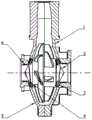
如图1所示,一种磁液耦合被动悬浮式双吸离心血泵,包括右蜗壳1,转子2,悬浮永磁磁环3,悬浮永磁磁片4,左蜗壳5,电机线圈6。As shown in Figure 1, a magnetic-fluid coupling passive suspension type double-suction centrifugal blood pump includes a right volute 1, a
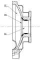
如图2所示为本发明左蜗壳结构示意图。左蜗壳内部腔体形状分为左入口5A,圆台形空腔5B,球形空腔5C,左蜗壳内部镶嵌有悬浮永磁磁环3。Figure 2 is a schematic diagram of the structure of the left volute of the present invention. The shape of the inner cavity of the left volute is divided into a
如图3所示为本发明右蜗壳结构示意图。右蜗壳内部腔体形状分为右入口1A,圆台形空腔1B,球形空腔1C,右蜗壳的内部镶嵌有悬浮永磁磁环3。Figure 3 is a schematic diagram of the structure of the right volute of the present invention. The shape of the inner cavity of the right volute is divided into a right inlet 1A, a truncated
如图4所示,转子2由圆锥实体2A,等距螺旋导流槽2B,右叶轮2C,左叶轮2D,圆柱实体2E等构成,圆锥实体2A内部镶嵌有悬浮永磁磁片4。右叶轮2C和左叶轮2D,左叶轮与右叶轮相邻的两个叶轮末端端面中心线所构成的夹角α为3~4o,箭头所指方向为转子2上流体流动的方向,等距螺旋导流槽2B的螺距为13~15mm,高度为28~30mm。As shown in FIG. 4 , the
如图5所示,右叶轮2C的结构示意图,R1、R2、R3、R4为过渡圆角,圆角半径为1.5~2.5mm,L1、L2、L3、L4为弧长,其弧长分别为56.3~56.8mm,24.5~25.0mm,62.5~63.0mm,34.4~34.9mm,在转子2上均匀分布,数量为6~8个。As shown in Figure 5, the structural diagram of the
如图6所示,左叶轮2D的结构示意图,R1、R2、R3、R4为过渡圆角,圆角半径为1.5~2.5mm,L1、L2、L3、L4为弧长,其弧长分别为19.8~20.3mm,76.7~77.2mm, 66.8~67.3mm,11.7~12.2mm,在转子2上均匀分布,数量为6~8个。As shown in Figure 6, the structural diagram of the
如图7所示,血液从左入口5A,右入口1A处进入血泵,电机线圈6通电后产生旋转磁场,驱动转子内悬浮永磁磁片4旋转,带动左叶轮2D和右叶轮2C旋转,产生离心力,右叶轮2C和左叶轮2D改变血液的流动方向,血液流经左蜗壳5、右蜗壳1与转子2的圆锥实体2A表面之间的间隙,从血泵出口流出。As shown in Figure 7, the blood enters the blood pump from the
如图8所示,悬浮永磁磁环3与悬浮永磁磁片4之间产生排斥力F1、F2、F3、F4。在使用时,需要保证该悬浮永磁磁片4与左蜗壳5以及右蜗壳1上的的悬浮永磁磁环3的充磁范围一一对应,磁片与磁环之间需要根据蜗壳的形状而平行设置。其中右蜗壳1的圆台形空腔1B与转子2的圆锥实体2A表面之间的间隙为0.8~1.2mm;左蜗壳5的圆台形空腔5B与转子2的圆锥实体2A表面之间的间隙为0.8~1.2mm。As shown in FIG. 8 , repulsive forces F1 , F2 , F3 , and F4 are generated between the suspended
以上所述,仅为本发明的具体实施方式,凡在本发明的范围和原则之内,所做的任何修改、改进、等同替换等,均应包含在本发明的保护范围之内。The above is only a specific implementation of the present invention, and any modification, improvement, equivalent replacement, etc. made within the scope and principles of the present invention shall be included in the protection scope of the present invention.
Claims (3)
Translated fromChinesePriority Applications (1)
| Application Number | Priority Date | Filing Date | Title |
|---|---|---|---|
| CN202010780806.2ACN111870752B (en) | 2020-08-06 | 2020-08-06 | A magnetic fluid coupling passive suspension double-suction centrifugal blood pump |
Applications Claiming Priority (1)
| Application Number | Priority Date | Filing Date | Title |
|---|---|---|---|
| CN202010780806.2ACN111870752B (en) | 2020-08-06 | 2020-08-06 | A magnetic fluid coupling passive suspension double-suction centrifugal blood pump |
Publications (2)
| Publication Number | Publication Date |
|---|---|
| CN111870752A CN111870752A (en) | 2020-11-03 |
| CN111870752Btrue CN111870752B (en) | 2023-05-12 |
Family
ID=73210747
Family Applications (1)
| Application Number | Title | Priority Date | Filing Date |
|---|---|---|---|
| CN202010780806.2AActiveCN111870752B (en) | 2020-08-06 | 2020-08-06 | A magnetic fluid coupling passive suspension double-suction centrifugal blood pump |
Country Status (1)
| Country | Link |
|---|---|
| CN (1) | CN111870752B (en) |
Families Citing this family (6)
| Publication number | Priority date | Publication date | Assignee | Title |
|---|---|---|---|---|
| CN114165456B (en)* | 2021-12-17 | 2022-10-28 | 浙江大学 | Centrifugal pump based on magnetic-liquid double-suspension structure |
| CN115143139B (en)* | 2022-07-20 | 2023-05-05 | 扬州大学 | Floating impeller centrifugal pump with automatic limiting function and design method thereof |
| CN115887908A (en)* | 2022-10-20 | 2023-04-04 | 北京航空航天大学 | artificial heart, blood pump |
| CN115501476A (en)* | 2022-10-21 | 2022-12-23 | 重庆凯磁智能科技研究院有限公司 | Unsettled strutting arrangement of rotor for blood pump |
| CN115405536A (en)* | 2022-10-31 | 2022-11-29 | 季华实验室 | A magnetically suspended double-suction centrifugal compressor |
| CN116570832A (en)* | 2023-03-30 | 2023-08-11 | 济南大学 | Centrifugal blood pump using magnetic suspension bearing and working method |
Family Cites Families (9)
| Publication number | Priority date | Publication date | Assignee | Title |
|---|---|---|---|---|
| US4944748A (en)* | 1986-10-12 | 1990-07-31 | Bramm Gunter W | Magnetically suspended and rotated rotor |
| US5055005A (en)* | 1990-10-05 | 1991-10-08 | Kletschka Harold D | Fluid pump with levitated impeller |
| US5195877A (en)* | 1990-10-05 | 1993-03-23 | Kletschka Harold D | Fluid pump with magnetically levitated impeller |
| US5924848A (en)* | 1995-06-01 | 1999-07-20 | Advanced Bionics, Inc. | Blood pump having radial vanes with enclosed magnetic drive components |
| US6206659B1 (en)* | 1995-06-01 | 2001-03-27 | Advanced Bionics, Inc. | Magnetically driven rotor for blood pump |
| DE20004136U1 (en)* | 2000-03-04 | 2000-12-14 | Krankenhausbetr Sgesellschaft | Blood pump |
| CN104307063B (en)* | 2014-10-17 | 2017-01-18 | 山东科技大学 | Magnetic resistance suspension centrifugal type device |
| CN104324428B (en)* | 2014-10-17 | 2016-08-17 | 山东科技大学 | A kind of centrifugal device of magnetic liquid suspension |
| CN105169504B (en)* | 2015-10-19 | 2017-05-17 | 济南大学 | Magnetic fluid coupling type passive suspension axial-flow blood pump |
- 2020
- 2020-08-06CNCN202010780806.2Apatent/CN111870752B/enactiveActive
Also Published As
| Publication number | Publication date |
|---|---|
| CN111870752A (en) | 2020-11-03 |
Similar Documents
| Publication | Publication Date | Title |
|---|---|---|
| CN111870752B (en) | A magnetic fluid coupling passive suspension double-suction centrifugal blood pump | |
| CN108175884B (en) | Ventricular assist pump | |
| CN105169504B (en) | Magnetic fluid coupling type passive suspension axial-flow blood pump | |
| CN107261231A (en) | A kind of Axial feedback controls magnetic levitation axial flow blood pump | |
| CN107890590B (en) | Dynamic magnetic balance suspension centrifugal blood pump | |
| CN102247628B (en) | Implantable magnetic liquid suspension centrifugal blood pump | |
| US20210220635A1 (en) | Centrifugal blood pump | |
| US5195877A (en) | Fluid pump with magnetically levitated impeller | |
| CN101732769A (en) | Implantable blood pump adopting driven suspension bearing | |
| CN105477706B (en) | Double Stator Mixed Support Artificial Heart Pump | |
| WO2018145434A1 (en) | Suspended centrifugal blood pump having alternating rotating impellers | |
| CN104258481B (en) | Magnetic suspension axial flow type spiral driving device | |
| CN211096485U (en) | External magnetic suspension centrifugal blood pump with central magnetic pole structure | |
| CN101601875A (en) | Suspension bearings for blood passive control in implantable centrifugal blood pumps | |
| CN111001056A (en) | Magnetic suspension axial flow type blood pump | |
| CN105343950B (en) | A kind of artificial blood pump of use Hydrodynamic suspension bearing | |
| CN115282466A (en) | Full magnetic suspension centrifugal blood pump | |
| CN107469169A (en) | A kind of band have dislocation design radial permanent magnet bearing axial blood pump | |
| CN101016906A (en) | Permanent magnet suspension bearing centrifugal pump | |
| CN115445075B (en) | Magnetic suspension pressurizing driving assembly of magnetic suspension axial end double-motor blood pump | |
| CN205055004U (en) | Adopt artifical blood pump of hydraulic suspension bearing | |
| CN213527129U (en) | Artificial heart pump with magnetic liquid suspension structure | |
| CN205055005U (en) | Magnetism liquid manifold type axial compressor blood pump that suspends passively | |
| Qian et al. | Permanent magnetic-levitation of rotating impeller: a decisive breakthrough in the centrifugal pump | |
| CN112516454A (en) | Magnetic suspension artificial heart pump |
Legal Events
| Date | Code | Title | Description |
|---|---|---|---|
| PB01 | Publication | ||
| PB01 | Publication | ||
| SE01 | Entry into force of request for substantive examination | ||
| SE01 | Entry into force of request for substantive examination | ||
| GR01 | Patent grant | ||
| GR01 | Patent grant |