CN111870296A - Anastomat - Google Patents
AnastomatDownload PDFInfo
- Publication number
- CN111870296A CN111870296ACN202010895764.7ACN202010895764ACN111870296ACN 111870296 ACN111870296 ACN 111870296ACN 202010895764 ACN202010895764 ACN 202010895764ACN 111870296 ACN111870296 ACN 111870296A
- Authority
- CN
- China
- Prior art keywords
- rack
- tooth
- teeth
- staple cartridge
- firing
- Prior art date
- Legal status (The legal status is an assumption and is not a legal conclusion. Google has not performed a legal analysis and makes no representation as to the accuracy of the status listed.)
- Granted
Links
Images


Classifications
- A—HUMAN NECESSITIES
- A61—MEDICAL OR VETERINARY SCIENCE; HYGIENE
- A61B—DIAGNOSIS; SURGERY; IDENTIFICATION
- A61B17/00—Surgical instruments, devices or methods
- A61B17/068—Surgical staplers, e.g. containing multiple staples or clamps
- A61B17/072—Surgical staplers, e.g. containing multiple staples or clamps for applying a row of staples in a single action, e.g. the staples being applied simultaneously
- A61B17/07207—Surgical staplers, e.g. containing multiple staples or clamps for applying a row of staples in a single action, e.g. the staples being applied simultaneously the staples being applied sequentially
- A—HUMAN NECESSITIES
- A61—MEDICAL OR VETERINARY SCIENCE; HYGIENE
- A61B—DIAGNOSIS; SURGERY; IDENTIFICATION
- A61B17/00—Surgical instruments, devices or methods
- A61B17/068—Surgical staplers, e.g. containing multiple staples or clamps
- A61B17/072—Surgical staplers, e.g. containing multiple staples or clamps for applying a row of staples in a single action, e.g. the staples being applied simultaneously
- A61B2017/07214—Stapler heads
- A61B2017/07235—Stapler heads containing different staples, e.g. staples of different shapes, sizes or materials
- A—HUMAN NECESSITIES
- A61—MEDICAL OR VETERINARY SCIENCE; HYGIENE
- A61B—DIAGNOSIS; SURGERY; IDENTIFICATION
- A61B17/00—Surgical instruments, devices or methods
- A61B17/068—Surgical staplers, e.g. containing multiple staples or clamps
- A61B17/072—Surgical staplers, e.g. containing multiple staples or clamps for applying a row of staples in a single action, e.g. the staples being applied simultaneously
- A61B2017/07214—Stapler heads
- A61B2017/07271—Stapler heads characterised by its cartridge
Landscapes
- Health & Medical Sciences (AREA)
- Life Sciences & Earth Sciences (AREA)
- Surgery (AREA)
- Heart & Thoracic Surgery (AREA)
- Engineering & Computer Science (AREA)
- Biomedical Technology (AREA)
- Nuclear Medicine, Radiotherapy & Molecular Imaging (AREA)
- Medical Informatics (AREA)
- Molecular Biology (AREA)
- Animal Behavior & Ethology (AREA)
- General Health & Medical Sciences (AREA)
- Public Health (AREA)
- Veterinary Medicine (AREA)
- Surgical Instruments (AREA)
Abstract
Description
Translated fromChinese技术领域technical field
本发明涉及医疗器械技术领域,更具体地说,涉及一种吻合器。The present invention relates to the technical field of medical devices, and more particularly, to a stapler.
背景技术Background technique
吻合器作为手工缝合的替代设备,利用钛钉对组织进行离断或吻合,主要用于腔镜下消化道重建及脏器切除手术中残端或切口的闭合,也可用于肝实质、胰脏、肾脏和脾脏的离断与切除,适用于多种开放或微创的普通外科、妇产科、泌尿外科、胸外科以及儿科手术。As an alternative to manual suturing, the stapler uses titanium nails to cut off or anastomose tissue. It is mainly used for endoscopic gastrointestinal reconstruction and closure of stumps or incisions in organ resection. It can also be used for liver parenchyma and pancreas. , kidney and spleen amputation and resection, suitable for a variety of open or minimally invasive general surgery, obstetrics and gynecology, urology, thoracic surgery and pediatric surgery.
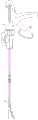
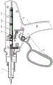
现有的吻合器大致分为两类,一类器械主体1和执行部件2为整体,如图1所示,吻合器击发时切割到的行进距离固定,即只能安装固定长度的钉仓,故在病人的病体组织需要不同切除长度时需要不同的吻合器,增加了病人的就医成本;另一类器械主体1和执行部件2分开,器械主体1可适用不同长度的执行部件2,如图2所示,由于器械主体1的击发长度需适应最长钉仓,对于短行程的缝合钉仓击发时无法确定行程的终点,存在不停击发的可能性,并导致切割刀断裂或器械破坏,且无法回拉切割刀复位、可能给病人造成致命伤害。Existing staplers are roughly divided into two categories. In the first category, the instrument body 1 and the
综上所述,如何适应不同的钉仓组件并根据不同的钉仓组件设置不同的击发距离,是目前本领域技术人员亟待解决的问题。To sum up, how to adapt to different staple cartridge assemblies and set different firing distances according to different staple cartridge assemblies is an urgent problem to be solved by those skilled in the art at present.
发明内容SUMMARY OF THE INVENTION
有鉴于此,本发明的目的是提供一种吻合器,通过设置齿条非全齿和齿条拨片挡块位置可调,实现了根据不同钉仓组件设置不同击发距离的功能。In view of this, the purpose of the present invention is to provide a stapler, which realizes the function of setting different firing distances according to different staple cartridge components by setting the rack partial teeth and the position of the rack pick block to be adjustable.
为了实现上述目的,本发明提供如下技术方案:In order to achieve the above object, the present invention provides the following technical solutions:
一种吻合器,包括执行部件和安装所述执行部件的器械主体,所述器械主体包括壳体、与所述壳体枢接的击发手柄、齿条、齿条拨片以及齿条拨片挡板,所述击发手柄通过所述齿条拨片与所述齿条连接;A stapler, comprising an execution part and an instrument body on which the execution part is mounted, the instrument body comprising a housing, a firing handle pivotally connected to the housing, a rack, a rack pick and a rack pick stop a plate, the firing handle is connected with the rack through the rack pick;
所述齿条为间隔齿形,所述齿条上设有位于第一钉仓极限击发位置处的A齿和位于第二钉仓极限击发位置处的B齿,所述A齿与所述B齿之间无齿形结构,所述第一钉仓的长度小于所述第二钉仓的长度;The rack is in the shape of spaced teeth, and the rack is provided with A teeth at the limit firing position of the first nail cartridge and B teeth at the limit firing position of the second nail cartridge, and the A teeth are connected with the B teeth. There is no tooth structure between the teeth, and the length of the first staple cartridge is less than the length of the second staple cartridge;
所述齿条拨片挡板与所述壳体滑动连接,且所述执行部件内安装的钉仓长度越大,所述齿条拨片挡板距所述击发手柄的旋转中心越远。The rack paddle baffle is slidably connected to the housing, and the longer the length of the nail cartridge installed in the execution part, the farther the rack paddle baffle is from the rotation center of the firing handle.
优选的,所述齿条上还有位于第三钉仓极限击发位置处的C齿,所述B齿与所述C齿之间无齿形结构;Preferably, there is also a C tooth located at the limit firing position of the third staple cartridge on the rack, and there is no tooth structure between the B tooth and the C tooth;
所述第二钉仓的长度小于所述第三钉仓的长度。The length of the second staple cartridge is less than the length of the third staple cartridge.
优选的,所述壳体与所述齿条拨片挡板中的一者设有滑槽,另一者设有与所述滑槽卡接配合的滑块;Preferably, one of the housing and the rack and paddle baffle is provided with a chute, and the other is provided with a slider that is snap-fitted with the chute;
所述齿条拨片挡板远离所述击发手柄的一端与壳体通过弹性件连接。One end of the rack and paddle baffle plate away from the firing handle is connected to the housing through an elastic member.
优选的,所述弹性件的一端与所述壳体固定连接,另一端与所述齿条拨片挡板的端面抵接或连接。Preferably, one end of the elastic member is fixedly connected with the housing, and the other end is abutted or connected with the end face of the rack and pick baffle.
优选的,所述滑槽的数量为两条,两条所述滑槽分别与所述齿条拨片挡板的两端垂直。Preferably, the number of the sliding grooves is two, and the two sliding grooves are respectively perpendicular to both ends of the rack and pick baffles.
优选的,所述齿条的击发起点与所述A齿之间设有若干个连续齿。Preferably, several continuous teeth are provided between the firing point of the rack and the A teeth.
优选的,所述连续齿、所述A齿、所述B齿以及所述C齿四者的齿形均相同。Preferably, the tooth shapes of the continuous teeth, the A teeth, the B teeth and the C teeth are all the same.
本发明提供的吻合器,包括执行部件和安装执行部件的器械主体,器械主体包括壳体、与壳体枢接的击发手柄、齿条、齿条拨片以及齿条拨片挡板,击发手柄通过齿条拨片与齿条连接;齿条为间隔齿形,齿条上设有位于第一钉仓极限击发位置处的A齿和位于第二钉仓极限击发位置处的B齿,A齿与B齿之间无齿形结构,第一钉仓的长度小于第二钉仓的长度;齿条拨片挡板与壳体滑动连接,且执行部件内安装的钉仓长度越大,齿条拨片挡板距击发手柄的旋转中心越远。The stapler provided by the present invention includes an execution part and an instrument body on which the execution part is installed. The instrument body includes a casing, a firing handle pivotally connected to the casing, a rack, a rack paddle, and a rack paddle baffle; the firing handle The rack is connected to the rack through the rack pick; the rack is in the form of spaced teeth, and the rack is provided with A teeth at the limit firing position of the first nail magazine and B teeth at the limit firing position of the second nail magazine. There is no toothed structure with B teeth, the length of the first nail cartridge is less than the length of the second nail cartridge; the rack paddle baffle is slidably connected to the housing, and the longer the length of the nail cartridge installed in the actuator, the longer the rack The further the paddle guard is from the center of rotation of the firing handle.
需要进行说明的是,此处第一钉仓和第二钉仓的具体长度可以根据实际手术中的需要进行确定,当然也可根据实际需要在B齿后设置位于第三极限钉仓极限击发位置处的C齿、位于第四极限钉仓极限击发位置处的D齿等(B齿与C齿之间以及C齿与D齿之间无齿形结构)。It should be noted that the specific lengths of the first nail cartridge and the second nail cartridge can be determined according to the actual needs in the operation, and of course, it can also be set at the limit firing position of the third limit nail cartridge after the B tooth according to the actual needs. The C tooth at the fourth limit, the D tooth at the limit firing position of the fourth limit cartridge, etc. (there is no tooth structure between the B tooth and the C tooth and between the C tooth and the D tooth).
击发手柄击发后,齿条拨片与齿条上的齿形接触并带动齿条向靠近执行部件的方向运动。安装第一钉仓时,在齿条拨片挡板的限制下,齿条拨片可接触的极限位置为A齿,当齿条拨片抵住A齿时,执行部件执行到位、切割和缝合组织到极限位置,此时再次击发击发手柄,由于齿条拨片无法与B齿抵接,执行部件无法继续前进;对于安装第二钉仓的情况,由于齿条拨片挡板距击发手柄的旋转中心更远,齿条拨片仍可与B齿抵接,故在到达第一钉仓的行程尾端后执行部件仍可继续前进,直至前进至第二钉仓的行程尾端。After the firing handle is fired, the rack pick contacts with the teeth on the rack and drives the rack to move in a direction close to the execution part. When installing the first staple cartridge, under the limitation of the rack pick plate, the limit position that the rack pick can contact is the A tooth. When the rack pick touches the A tooth, the execution part is in place, cutting and sewing. The organization reaches the limit position, and the firing handle is fired again at this time. Since the rack paddle cannot abut with the B tooth, the execution part cannot continue to move forward; for the case of installing the second nail cartridge, because the rack paddle baffle is far from the firing handle. The rotation center is further away, and the rack pick can still abut with the B tooth, so the actuator can continue to move forward after reaching the end of the stroke of the first magazine until it reaches the end of the stroke of the second magazine.
因此,本发明提供的吻合器既可适用于不同规格的钉仓,又实现了根据不同的钉仓组件设置不同的击发距离,解决了短行程钉仓到达行程尾端后仍可继续击发的问题,避免了器械损坏或者对病人的额外伤害。Therefore, the stapler provided by the present invention is not only applicable to staple cartridges of different specifications, but also realizes that different firing distances can be set according to different staple cartridge components, and solves the problem that the short-stroke staple cartridge can still be fired after reaching the end of the stroke. , to avoid equipment damage or additional injury to the patient.
附图说明Description of drawings
为了更清楚地说明本发明实施例或现有技术中的技术方案,下面将对实施例或现有技术描述中所需要使用的附图作简单地介绍,显而易见地,下面描述中的附图仅仅是本发明的实施例,对于本领域普通技术人员来讲,在不付出创造性劳动的前提下,还可以根据提供的附图获得其他的附图。In order to explain the embodiments of the present invention or the technical solutions in the prior art more clearly, the following briefly introduces the accompanying drawings that need to be used in the description of the embodiments or the prior art. Obviously, the accompanying drawings in the following description are only It is an embodiment of the present invention. For those of ordinary skill in the art, other drawings can also be obtained according to the provided drawings without creative work.
图1为现有技术中适配单一钉仓的吻合器的结构示意图;1 is a schematic structural diagram of a stapler adapted to a single staple cartridge in the prior art;
图2为现有技术中适配多种钉仓的吻合器的结构示意图;2 is a schematic structural diagram of a stapler adapted to a variety of staple cartridges in the prior art;
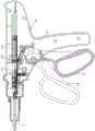
图3为本发明所提供的吻合器的具体实施例的击发构造示意图;3 is a schematic diagram of the firing structure of a specific embodiment of the stapler provided by the present invention;
图4为图3中的齿条的结构示意图;FIG. 4 is a schematic structural diagram of the rack in FIG. 3;
图5为图3中的吻合器击发30钉仓时的分解示意图;FIG. 5 is an exploded schematic view of the stapler in FIG. 3 when firing 30 staple cartridges;
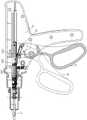
图6为图3中的吻合器击发45钉仓时的分解示意图。FIG. 6 is an exploded schematic view of the stapler in FIG. 3 when the staple cartridge 45 is fired.
图1-图6中:In Figure 1-Figure 6:
1为器械主体、11为壳体、12为击发手柄、13为齿条拨片、14为齿条、141为A齿、142为B齿、143为C齿、144为连续齿、15为齿条拨片挡板、2为执行部件。1 is the main body of the instrument, 11 is the shell, 12 is the firing handle, 13 is the rack paddle, 14 is the rack, 141 is the A tooth, 142 is the B tooth, 143 is the C tooth, 144 is the continuous tooth, and 15 is the tooth The paddle baffle and 2 are the executive parts.
具体实施方式Detailed ways
下面将结合本发明实施例中的附图,对本发明实施例中的技术方案进行清楚、完整地描述,显然,所描述的实施例仅仅是本发明一部分实施例,而不是全部的实施例。基于本发明中的实施例,本领域普通技术人员在没有做出创造性劳动前提下所获得的所有其他实施例,都属于本发明保护的范围。The technical solutions in the embodiments of the present invention will be clearly and completely described below with reference to the accompanying drawings in the embodiments of the present invention. Obviously, the described embodiments are only a part of the embodiments of the present invention, but not all of the embodiments. Based on the embodiments of the present invention, all other embodiments obtained by those of ordinary skill in the art without creative efforts shall fall within the protection scope of the present invention.
本发明的核心是提供一种吻合器,通过设置齿条非全齿和齿条拨片挡块位置可调,实现了根据不同钉仓组件设置不同击发距离的功能。The core of the present invention is to provide a stapler, which realizes the function of setting different firing distances according to different staple cartridge components by setting the racks with incomplete teeth and the position of the rack pick-up block adjustable.
请参考图1-图6,图1为现有技术中适配单一钉仓的吻合器的结构示意图;图2为现有技术中适配多种钉仓的吻合器的结构示意图;图3为本发明所提供的吻合器的具体实施例的击发构造示意图;图4为图3中的齿条的结构示意图;图5为图3中的吻合器击发30钉仓时的分解示意图;图6为图3中的吻合器击发45钉仓时的分解示意图。Please refer to FIGS. 1-6 . FIG. 1 is a schematic structural diagram of a stapler adapted to a single staple cartridge in the prior art; FIG. 2 is a schematic structural diagram of a stapler adapted to multiple staple cartridges in the prior art; A schematic diagram of the firing structure of a specific embodiment of the stapler provided by the present invention; FIG. 4 is a schematic diagram of the structure of the rack in FIG. 3 ; FIG. 5 is an exploded schematic diagram of the stapler in FIG. An exploded schematic view of the stapler in FIG. 3 when the staple cartridge is fired 45 .
本发明提供的吻合器,包括执行部件2和安装执行部件2的器械主体1,器械主体1包括壳体11、与壳体11枢接的击发手柄12、齿条14、齿条拨片13以及齿条拨片挡板15,击发手柄12通过齿条拨片13与齿条14连接;齿条14为间隔齿形,齿条14上设有位于第一钉仓极限击发位置处的A齿141和位于第二钉仓极限击发位置处的B齿142,A齿141与B齿142之间无齿形结构,第一钉仓的长度小于第二钉仓的长度;齿条拨片挡板15与壳体11滑动连接,且执行部件2内安装的钉仓长度越大,齿条拨片挡板15距击发手柄12的旋转中心越远。The stapler provided by the present invention includes an
A齿141和B齿142分别代表第一钉仓的极限击发位置和第二钉仓的极限击发位置,即齿条14的击发起点到A齿141的距离等于第一钉仓的行程长度,齿条14的击发起点到B齿142的距离等于第二钉仓的行程长度。The
需要进行说明的是,此处第一钉仓和第二钉仓的具体长度可以根据实际手术操作中的需要进行确定,当然也可根据实际需要在B齿142后设置位于第三极限钉仓极限击发位置处的C齿143、位于第四极限钉仓极限击发位置处的D齿等(B齿与C齿之间以及C齿与D齿之间无齿形结构)。It should be noted that the specific lengths of the first staple cartridge and the second staple cartridge can be determined according to the needs of actual surgical operations. Of course, it can also be set at the third limit staple cartridge limit after the
齿条拨片挡板15的位置受到执行部位2钉仓长度的影响,由于齿条拨片挡板15靠近击发手柄12的一端与执行部件2抵接,装入的钉仓长度越长,齿条拨片挡板15距离击发手柄12越远。The position of the
齿条拨片挡板15与壳体11滑动连接,以满足改变齿条拨片挡板15到击发手柄12的旋转中心的距离的需要。优选的,壳体11与齿条拨片挡板15中的一者可以设有滑槽,另一者可以设有与滑槽卡接配合的滑块;齿条拨片挡板15远离击发手柄12的一端与壳体11通过弹性件连接。The
优选的,弹性件的一端与壳体11固定连接,另一端与齿条拨片挡板15的端面抵接或连接。Preferably, one end of the elastic member is fixedly connected to the
当弹性件仅与齿条拨片挡板15的端面抵接时,考虑到齿条拨片挡板15的复位问题,应当设置滑槽的长度等于或大于弹性件的自然长度。When the elastic piece only abuts the end face of the
优选的,可以选择弹簧作为弹性件,弹簧的材料和尺寸等参数请根据实际生产的需要参考现有技术,在此不再赘述。Preferably, a spring can be selected as the elastic member. For parameters such as the material and size of the spring, please refer to the prior art according to actual production needs, and will not be repeated here.
因此,齿条拨片挡板15的一端被执行部件2抵接,另一端与弹性件连接,实现了根据执行部件2的长度改变齿条拨片档位15的位置。Therefore, one end of the rack
优选的,滑槽的数量可以为两条,且两条滑槽分别与齿条拨片挡板15的两端垂直,以提高齿条拨片挡板15与壳体11间滑动连接的稳定性。Preferably, the number of the sliding grooves can be two, and the two sliding grooves are respectively perpendicular to both ends of the
此外,也可以在壳体11上设有若干个对应不同钉仓的档位,通过手动调节方式改变齿条拨片挡板15的档位。In addition, several gear positions corresponding to different nail cartridges can also be provided on the
击发手柄12击发后,齿条拨片13与齿条14上的齿形接触并带动齿条14向靠近执行部件2的方向运动。安装第一钉仓时,请参考图5,在齿条拨片挡板15的限制下,齿条拨片13可接触的极限位置为A齿141,当齿条拨片13抵住A齿141时,执行部件2执行到位、切割和缝合组织到极限位置,此时再次击发击发手柄12,由于齿条拨片13无法与B齿142抵接,执行部件2无法继续前进;对于安装第二钉仓的情况,由于齿条拨片挡板15距击发手柄12的旋转中心更远,齿条拨片13仍可与B齿142抵接,故在到达第一钉仓的行程尾端后执行部件2仍可继续前进,直至前进至第二钉仓的行程尾端。After the firing handle 12 is fired, the
因此,本发明提供的吻合器既可适用于不同规格的钉仓,又实现了根据不同的钉仓组件设置不同的击发距离,解决了短行程钉仓到达行程尾端后仍可继续击发的问题,避免了器械损坏或者对病人的额外伤害。Therefore, the stapler provided by the present invention is not only applicable to staple cartridges of different specifications, but also realizes that different firing distances can be set according to different staple cartridge components, and solves the problem that the short-stroke staple cartridge can still be fired after reaching the end of the stroke. , to avoid equipment damage or additional injury to the patient.
在上述实施例的基础上,齿条14上还可以设有位于第三钉仓极限击发位置处的C齿143,B齿142与C齿142之间无齿形结构;第二钉仓的长度小于第三钉仓的长度。On the basis of the above embodiment, the
请参考图6,安装第二钉仓时,受到齿条拨片挡板15的限制,齿条拨片13可接触的极限位置为B齿142,当齿条拨片13抵住B齿142时,执行部件2执行到位、切割和缝合组织到极限位置,此时再次击发击发手柄12,由于齿条拨片13无法与C齿143抵接,执行部件2无法继续前进;而安装第三钉仓的情况,由于齿条拨片挡板15距击发手柄12的旋转中心更远,齿条拨片13仍可与C齿143抵接,故在到达第二钉仓的行程尾端后执行部件2仍可继续前进,直至前进至第三钉仓的行程尾端。Please refer to FIG. 6 , when the second staple cartridge is installed, limited by the
在某一具体实施例中,齿条14上设有位于30钉仓极限位置处的A齿141、位于45钉仓极限位置处的B齿142以及位于60钉仓极限位置处的C齿143。In a specific embodiment, the
优选的,请参考图4,齿条14的击发起点与A齿141之间可以设有若干个连续齿144,以通过增加击发次数减少每次击发所需的击发力。Preferably, please refer to FIG. 4 , several
优选的,连续齿144、A齿141、B齿142和C齿143四者的齿形均相同,以方便齿条14的加工,降低生产成本。其具体齿形请根据实际生产中的需要参考现有技术进行确定,在此不再赘述。Preferably, the tooth shapes of the
本说明书中各个实施例采用递进的方式描述,每个实施例重点说明的都是与其他实施例的不同之处,各个实施例之间相同相似部分互相参见即可。The various embodiments in this specification are described in a progressive manner, and each embodiment focuses on the differences from other embodiments, and the same and similar parts between the various embodiments can be referred to each other.
以上对本发明所提供的吻合器进行了详细介绍。本文中应用了具体个例对本发明的原理及实施方式进行了阐述,以上实施例的说明只是用于帮助理解本发明的方法及其核心思想。应当指出,对于本技术领域的普通技术人员来说,在不脱离本发明原理的前提下,还可以对本发明进行若干改进和修饰,这些改进和修饰也落入本发明权利要求的保护范围内。The stapler provided by the present invention has been described in detail above. The principles and implementations of the present invention are described herein by using specific examples, and the descriptions of the above embodiments are only used to help understand the method and the core idea of the present invention. It should be pointed out that for those skilled in the art, without departing from the principle of the present invention, several improvements and modifications can also be made to the present invention, and these improvements and modifications also fall within the protection scope of the claims of the present invention.
Claims (7)
Translated fromChinesePriority Applications (1)
| Application Number | Priority Date | Filing Date | Title |
|---|---|---|---|
| CN202010895764.7ACN111870296B (en) | 2020-08-31 | 2020-08-31 | A stapler |
Applications Claiming Priority (1)
| Application Number | Priority Date | Filing Date | Title |
|---|---|---|---|
| CN202010895764.7ACN111870296B (en) | 2020-08-31 | 2020-08-31 | A stapler |
Publications (2)
| Publication Number | Publication Date |
|---|---|
| CN111870296Atrue CN111870296A (en) | 2020-11-03 |
| CN111870296B CN111870296B (en) | 2025-06-24 |
Family
ID=73198946
Family Applications (1)
| Application Number | Title | Priority Date | Filing Date |
|---|---|---|---|
| CN202010895764.7AActiveCN111870296B (en) | 2020-08-31 | 2020-08-31 | A stapler |
Country Status (1)
| Country | Link |
|---|---|
| CN (1) | CN111870296B (en) |
Cited By (2)
| Publication number | Priority date | Publication date | Assignee | Title |
|---|---|---|---|---|
| CN115089244A (en)* | 2022-06-27 | 2022-09-23 | 宝玛医疗科技(无锡)有限公司 | Electric anastomat suitable for nail bin assemblies with different lengths |
| CN115089245A (en)* | 2022-06-27 | 2022-09-23 | 宝玛医疗科技(无锡)有限公司 | Multi-gear switching electric anastomat |
Citations (12)
| Publication number | Priority date | Publication date | Assignee | Title |
|---|---|---|---|---|
| CN101507631A (en)* | 2008-02-14 | 2009-08-19 | 伊西康内外科公司 | Surgical stapling apparatus with load-sensitive firing mechanism |
| DE202014105791U1 (en)* | 2014-12-02 | 2014-12-09 | Jiin Haur Industrial Co., Ltd. | Adjustable pruning shears |
| CN106037847A (en)* | 2016-05-16 | 2016-10-26 | 江苏冠创医疗科技有限公司 | Anastomotic mechanism capable of being regulated by single hand for endoscope anastomat |
| CN106388894A (en)* | 2016-11-17 | 2017-02-15 | 马博平 | Novel cutting anastomat and operating method thereof |
| US20170143361A1 (en)* | 2015-11-24 | 2017-05-25 | Ethicon Endo-Surgery, Llc | Surgical Device with Anti-Binding Features |
| CN207235523U (en)* | 2017-09-30 | 2018-04-17 | 林洁清 | A kind of Labour-saving tree pruner of adjustable gear and stroke |
| CN207253350U (en)* | 2017-03-14 | 2018-04-20 | 江苏三联星海医疗器械股份有限公司 | The pressure tool retracting device of disposable hysteroscope Endo-GIA |
| CN109674500A (en)* | 2018-12-25 | 2019-04-26 | 上海逸思医疗科技有限公司 | A kind of safety device of surgical instruments |
| CN110279448A (en)* | 2019-07-27 | 2019-09-27 | 广西医科大学 | A kind of self-fitting type surgical operation operation handle |
| US20200008831A1 (en)* | 2017-03-08 | 2020-01-09 | Aesculap Ag | Surgical instrument with a coupling mechanism for driving a cutting element |
| CN111281461A (en)* | 2018-12-08 | 2020-06-16 | 江苏风和医疗器材股份有限公司 | Driving device, anti-jamming structure of transmission mechanism, steering piece and anastomat |
| CN212973003U (en)* | 2020-08-31 | 2021-04-16 | 山东威瑞外科医用制品有限公司 | Anastomat |
- 2020
- 2020-08-31CNCN202010895764.7Apatent/CN111870296B/enactiveActive
Patent Citations (12)
| Publication number | Priority date | Publication date | Assignee | Title |
|---|---|---|---|---|
| CN101507631A (en)* | 2008-02-14 | 2009-08-19 | 伊西康内外科公司 | Surgical stapling apparatus with load-sensitive firing mechanism |
| DE202014105791U1 (en)* | 2014-12-02 | 2014-12-09 | Jiin Haur Industrial Co., Ltd. | Adjustable pruning shears |
| US20170143361A1 (en)* | 2015-11-24 | 2017-05-25 | Ethicon Endo-Surgery, Llc | Surgical Device with Anti-Binding Features |
| CN106037847A (en)* | 2016-05-16 | 2016-10-26 | 江苏冠创医疗科技有限公司 | Anastomotic mechanism capable of being regulated by single hand for endoscope anastomat |
| CN106388894A (en)* | 2016-11-17 | 2017-02-15 | 马博平 | Novel cutting anastomat and operating method thereof |
| US20200008831A1 (en)* | 2017-03-08 | 2020-01-09 | Aesculap Ag | Surgical instrument with a coupling mechanism for driving a cutting element |
| CN207253350U (en)* | 2017-03-14 | 2018-04-20 | 江苏三联星海医疗器械股份有限公司 | The pressure tool retracting device of disposable hysteroscope Endo-GIA |
| CN207235523U (en)* | 2017-09-30 | 2018-04-17 | 林洁清 | A kind of Labour-saving tree pruner of adjustable gear and stroke |
| CN111281461A (en)* | 2018-12-08 | 2020-06-16 | 江苏风和医疗器材股份有限公司 | Driving device, anti-jamming structure of transmission mechanism, steering piece and anastomat |
| CN109674500A (en)* | 2018-12-25 | 2019-04-26 | 上海逸思医疗科技有限公司 | A kind of safety device of surgical instruments |
| CN110279448A (en)* | 2019-07-27 | 2019-09-27 | 广西医科大学 | A kind of self-fitting type surgical operation operation handle |
| CN212973003U (en)* | 2020-08-31 | 2021-04-16 | 山东威瑞外科医用制品有限公司 | Anastomat |
Cited By (3)
| Publication number | Priority date | Publication date | Assignee | Title |
|---|---|---|---|---|
| CN115089244A (en)* | 2022-06-27 | 2022-09-23 | 宝玛医疗科技(无锡)有限公司 | Electric anastomat suitable for nail bin assemblies with different lengths |
| CN115089245A (en)* | 2022-06-27 | 2022-09-23 | 宝玛医疗科技(无锡)有限公司 | Multi-gear switching electric anastomat |
| CN115089244B (en)* | 2022-06-27 | 2024-02-02 | 宝玛医疗科技(无锡)有限公司 | Electric anastomat applicable to nail bin assemblies with different lengths |
Also Published As
| Publication number | Publication date |
|---|---|
| CN111870296B (en) | 2025-06-24 |
Similar Documents
| Publication | Publication Date | Title |
|---|---|---|
| US20250057528A1 (en) | Surgical stapling device with adjustable dissecting tip | |
| AU2009201758B2 (en) | Surgical instrument with sequential clamping and cutting | |
| JP5143509B2 (en) | Surgical instrument with articulating tool assembly | |
| CN103860221B (en) | Linear stapling cutter nail-head component | |
| CN111870296A (en) | Anastomat | |
| CN204364049U (en) | A kind of nail-head component and chamber mirror surgical operation seaming and cutting device | |
| CN111542275B (en) | End effector, surgical stapling device, and methods of use thereof | |
| CN111938734A (en) | A stapler cartridge and stapler | |
| CN115568897B (en) | Anastomat with switch locking linkage mechanism | |
| CN115209818A (en) | Anvil assembly with cutting board | |
| CN212394992U (en) | A stapler cartridge and stapler | |
| CN219207120U (en) | Reduction device and surgical instrument | |
| CN217566159U (en) | Endoscope cutting closer with tip capable of adjusting bending angle | |
| CN101856252A (en) | Anastomat for minimally invasive surgery | |
| CN212973003U (en) | Anastomat | |
| US12334665B2 (en) | Surgical instrument with electrical connection | |
| CN217853125U (en) | Nail head and medical anastomat | |
| CN211155992U (en) | Drive mechanism and medical stapler | |
| CN213156138U (en) | Surgical stitching instrument with empty nail bin protection function | |
| CN113693657A (en) | Endoscopic stapler for linear push-pull cutting and suturing | |
| CN219461268U (en) | Surgical Stapler | |
| CN109953793B (en) | Handle assembly and stapler including same | |
| JP2023554080A (en) | Stapling device with curved end effector | |
| CN218899554U (en) | Endoscopic stapler execution assembly with guiding function and endoscopic stapler | |
| CN114680978B (en) | Surgical suture device |
Legal Events
| Date | Code | Title | Description |
|---|---|---|---|
| PB01 | Publication | ||
| PB01 | Publication | ||
| SE01 | Entry into force of request for substantive examination | ||
| SE01 | Entry into force of request for substantive examination | ||
| GR01 | Patent grant | ||
| GR01 | Patent grant |