CN111870211A - A three-dimensional endoscope with instrument pose navigation and its navigation method - Google Patents
A three-dimensional endoscope with instrument pose navigation and its navigation methodDownload PDFInfo
- Publication number
- CN111870211A CN111870211ACN202010739975.1ACN202010739975ACN111870211ACN 111870211 ACN111870211 ACN 111870211ACN 202010739975 ACN202010739975 ACN 202010739975ACN 111870211 ACN111870211 ACN 111870211A
- Authority
- CN
- China
- Prior art keywords
- camera
- dimensional
- endoscope
- navigation
- electromagnetic sensor
- Prior art date
- Legal status (The legal status is an assumption and is not a legal conclusion. Google has not performed a legal analysis and makes no representation as to the accuracy of the status listed.)
- Pending
Links
Images

Classifications
- A—HUMAN NECESSITIES
- A61—MEDICAL OR VETERINARY SCIENCE; HYGIENE
- A61B—DIAGNOSIS; SURGERY; IDENTIFICATION
- A61B1/00—Instruments for performing medical examinations of the interior of cavities or tubes of the body by visual or photographical inspection, e.g. endoscopes; Illuminating arrangements therefor
- A61B1/04—Instruments for performing medical examinations of the interior of cavities or tubes of the body by visual or photographical inspection, e.g. endoscopes; Illuminating arrangements therefor combined with photographic or television appliances
- A61B1/045—Control thereof
- A—HUMAN NECESSITIES
- A61—MEDICAL OR VETERINARY SCIENCE; HYGIENE
- A61B—DIAGNOSIS; SURGERY; IDENTIFICATION
- A61B1/00—Instruments for performing medical examinations of the interior of cavities or tubes of the body by visual or photographical inspection, e.g. endoscopes; Illuminating arrangements therefor
- A61B1/00147—Holding or positioning arrangements
- A—HUMAN NECESSITIES
- A61—MEDICAL OR VETERINARY SCIENCE; HYGIENE
- A61B—DIAGNOSIS; SURGERY; IDENTIFICATION
- A61B1/00—Instruments for performing medical examinations of the interior of cavities or tubes of the body by visual or photographical inspection, e.g. endoscopes; Illuminating arrangements therefor
- A61B1/06—Instruments for performing medical examinations of the interior of cavities or tubes of the body by visual or photographical inspection, e.g. endoscopes; Illuminating arrangements therefor with illuminating arrangements
- A61B1/07—Instruments for performing medical examinations of the interior of cavities or tubes of the body by visual or photographical inspection, e.g. endoscopes; Illuminating arrangements therefor with illuminating arrangements using light-conductive means, e.g. optical fibres
- G—PHYSICS
- G06—COMPUTING OR CALCULATING; COUNTING
- G06T—IMAGE DATA PROCESSING OR GENERATION, IN GENERAL
- G06T7/00—Image analysis
- G06T7/20—Analysis of motion
- G06T7/246—Analysis of motion using feature-based methods, e.g. the tracking of corners or segments
- G—PHYSICS
- G06—COMPUTING OR CALCULATING; COUNTING
- G06T—IMAGE DATA PROCESSING OR GENERATION, IN GENERAL
- G06T7/00—Image analysis
- G06T7/80—Analysis of captured images to determine intrinsic or extrinsic camera parameters, i.e. camera calibration
- G—PHYSICS
- G06—COMPUTING OR CALCULATING; COUNTING
- G06T—IMAGE DATA PROCESSING OR GENERATION, IN GENERAL
- G06T2207/00—Indexing scheme for image analysis or image enhancement
- G06T2207/10—Image acquisition modality
- G06T2207/10068—Endoscopic image
Landscapes
- Health & Medical Sciences (AREA)
- Life Sciences & Earth Sciences (AREA)
- Engineering & Computer Science (AREA)
- Surgery (AREA)
- Physics & Mathematics (AREA)
- Biomedical Technology (AREA)
- Animal Behavior & Ethology (AREA)
- Radiology & Medical Imaging (AREA)
- Optics & Photonics (AREA)
- Nuclear Medicine, Radiotherapy & Molecular Imaging (AREA)
- Biophysics (AREA)
- Heart & Thoracic Surgery (AREA)
- Medical Informatics (AREA)
- Molecular Biology (AREA)
- Pathology (AREA)
- General Health & Medical Sciences (AREA)
- Public Health (AREA)
- Veterinary Medicine (AREA)
- Computer Vision & Pattern Recognition (AREA)
- General Physics & Mathematics (AREA)
- Theoretical Computer Science (AREA)
- Multimedia (AREA)
- Instruments For Viewing The Inside Of Hollow Bodies (AREA)
Abstract
Translated fromChinese
Description
Translated fromChinese技术领域technical field
本发明涉及一种手术导航设备领域,特别是关于一种具有器具位姿导航的三维内窥镜及其导航方法。The present invention relates to the field of surgical navigation equipment, in particular to a three-dimensional endoscope with instrument posture navigation and a navigation method thereof.
背景技术Background technique
内窥镜是一种通过外科小切口进入帮助医师查看体内器官或组织表面结构的光学仪器。目前,大多数的30°-70°视觉内窥镜广泛应用于手术辅助检查中。然而,传统的内窥镜仅能提供不包含术野景深信息的二维图像,只能对术野范围进行术中观察,而无法提供手术目标的立体视觉感知,特别是内窥镜与目标物的相对距离感知。而且,传统内窥镜构造复杂、价格昂贵,尽管如此,由于缺乏相对距离感知带来的与体内硬物(如骨头)的碰撞经常发生,极其容易导致内窥镜末梢镜头的损害。在器具导航方面,常见的主要形式有光电跟踪式和电磁控制式。前者能够实现连续导航的前提条件是术中特别是手臂不能遮挡光电信号,否则导航信息会中断;后者通常需要一个电磁引导器去控制内窥镜(常见于胶囊内窥镜)的运动轨迹。二者均缺乏导航稳定性和操作便捷性。An endoscope is an optical instrument that is inserted through a small surgical incision to help physicians view the surface structure of an organ or tissue in the body. At present, most of the 30°-70° visual endoscopes are widely used in surgical auxiliary examinations. However, traditional endoscopes can only provide two-dimensional images without depth information of the operative field, and can only observe the scope of the operative field intraoperatively, but cannot provide stereoscopic vision perception of surgical targets, especially the endoscope and the target object. relative distance perception. Moreover, traditional endoscopes are complicated in structure and expensive. However, due to the lack of relative distance perception, collisions with hard objects (such as bones) in the body often occur, which is extremely easy to cause damage to the distal lens of the endoscope. In the aspect of appliance navigation, the common main forms are photoelectric tracking type and electromagnetic control type. The prerequisite for the former to achieve continuous navigation is that the arm, especially the arm, cannot block the photoelectric signal, otherwise the navigation information will be interrupted; the latter usually requires an electromagnetic guide to control the movement trajectory of the endoscope (commonly used in capsule endoscope). Both lack navigation stability and ease of operation.
发明内容SUMMARY OF THE INVENTION
针对上述问题,本发明的目的是提供一种具有器具位姿导航的三维内窥镜及其导航方法,其能完成被测曲面的三维重构并实时再现,且导航具有连续性,不受遮挡或信号的干扰。In view of the above problems, the purpose of the present invention is to provide a three-dimensional endoscope with device position and orientation navigation and a navigation method thereof, which can complete the three-dimensional reconstruction of the measured surface and reproduce it in real time, and the navigation has continuity and is not blocked. or signal interference.
为实现上述目的,本发明采取以下技术方案:一种具有器具位姿导航的三维内窥镜导航方法,其包括以下步骤:S1、将三维内窥镜的前端放置在距被测量表面一定距离处投射线激光,采集被测量表面的结构光,并分别对相机平面上的结构点进行提取和计算,获取曲面点云在内窥镜坐标系下的三维坐标值

进一步,所述步骤S1中,一定距离为3-10mm。Further, in the step S1, the certain distance is 3-10 mm.
进一步,所述步骤S1中,被测量表面的结构光采用摄像头进行采集。Further, in the step S1, the structured light of the surface to be measured is collected by a camera.
进一步,所述步骤S1中,将相机的光轴定义为Z轴,即深度方向,相机上侧定义为X轴,右侧即为Y轴;则每个被检测出来的激光点在内窥镜坐标系下的三维坐标值为:Further, in the step S1, the optical axis of the camera is defined as the Z axis, that is, the depth direction, the upper side of the camera is defined as the X axis, and the right side is the Y axis; then each detected laser point is the endoscope. The three-dimensional coordinate values in the coordinate system are:


式中,B为基线长度,即光纤先端与相机先端的距离值;f为相机焦距;(x,y)为激光点在相机平面上的二维坐标值;(cx,cy)为相机平面的投影中心坐标。In the formula, B is the baseline length, that is, the distance between the fiber tip and the camera tip; f is the camera focal length; (x, y) is the two-dimensional coordinate value of the laser point on the camera plane; (cx , cy ) is the camera The projected center coordinates of the plane.
进一步,所述步骤S2中,转换公式为:Further, in the step S2, the conversion formula is:

式中,Rs为电磁传感器三维旋转矩阵,且有Rs=RzRyRx,Rz、Ry、Rx分别是绕Z轴、Y轴、X轴的旋转,均为3*3的矩阵;
进一步,所述步骤S3中,采用Marching Cubes优化方法,在OpenGL下将电磁坐标系下的曲面点云渲染生成实体曲面。Further, in the step S3, the Marching Cubes optimization method is used to render the surface point cloud under the electromagnetic coordinate system under OpenGL to generate a solid surface.
进一步,所述实体曲面的生成方法具体步骤如下:Further, the specific steps of the method for generating the solid surface are as follows:
S31、设相邻两个格子顶点分别是Ci和Ci-1,则点云格子的间隔参数t=Ci-Ci-1;S31, suppose that two adjacent lattice vertices are Ci and Ci-1 respectively, then the interval parameter t=Ci -Ci-1 of the point cloud lattice;
S32、计算以CiCi-1为边长的正方体内每一个点云在边长CiCi-1上的投影,如果投影点di在边长中点的左侧,则该点云配置给顶点Ci,否则配置给Ci-1;S32. Calculate the projection of each point cloud in the cube with Ci Ci-1 as the side length on the side length Ci Ci-1 . If the projected point di is on the left side of the midpoint of the side length, then the point Cloud is assigned to vertex Ci , otherwise assigned to Ci-1 ;
S33、根据顶点的分布状态,提取符合预设条件的三角形曲面,根据提取的三角形曲面生成8位二维数值的索引;S33, according to the distribution state of the vertices, extract the triangular surface that meets the preset condition, and generate the index of the 8-bit two-dimensional value according to the extracted triangular surface;
S34、根据8位二维数值的索引获得曲面抽取的类型,完成曲面渲染,生成可视化曲面。S34. Obtain the type of surface extraction according to the index of the 8-bit two-dimensional value, complete surface rendering, and generate a visualized surface.
进一步,所述步骤S5中,具体导航方法包括以下步骤:Further, in the step S5, the specific navigation method includes the following steps:
S51、在以重心G为圆心,r为半径的圆上搜索三个点云,当且仅当能够组成一个等边三角形时,存储这三个点云的三维坐标,记三角形的顶点分别为P1,P2,P3;S51. Search for three point clouds on a circle with the center of gravity G as the center and r as the radius, if and only if an equilateral triangle can be formed, store the three-dimensional coordinates of the three point clouds, and record the vertices of the triangle as P respectively1 , P2 , P3 ;
S52、计算获得的等边三角形任意两边的向量积,求得等边三角形极小邻域内的法向量,则过重心G的法向量即为器具在当前曲面的实时姿态向量,此时重心G的坐标即为器具的当前位置;S52. Calculate the vector product of any two sides of the obtained equilateral triangle, and obtain the normal vector in the minimal neighborhood of the equilateral triangle, then the normal vector passing through the center of gravity G is the real-time attitude vector of the appliance on the current surface. The coordinates are the current position of the appliance;
S53、把步骤S52的法向量,以及器具实时姿态向量,通过OpenGL图像显示再现在显示屏上,完成导航。S53 , displaying the normal vector in step S52 and the real-time attitude vector of the appliance on the display screen through OpenGL image display to complete the navigation.
一种用于实现上述导航方法的三维内窥镜,其包括:摄像头、光纤、电磁传感器和内窥镜探管;所述摄像头、光纤和电磁传感器均设置在所述内窥镜探管内,且所述摄像头、光纤和电磁传感器呈三角形排列布置,三者形成的三角形几何结构存储至上位机内;氦氖激光器与耦合镜设置在所述光纤的一端,所述氦氖激光器投射出的线激光经所述耦合镜后由所述光纤发出,投射在所述被测量曲面上形成与所述被测量曲面相一致的结构光,并由所述摄像头采集该结构光后传输至所述上位机;所述电磁传感器采集当前内窥镜的相对位置和姿态信息并传输至所述上位机,实现对所述摄像头运动状态的跟踪。A three-dimensional endoscope for implementing the above navigation method, comprising: a camera, an optical fiber, an electromagnetic sensor and an endoscope probe; the camera, the optical fiber and the electromagnetic sensor are all arranged in the endoscope probe, and The camera, the optical fiber and the electromagnetic sensor are arranged in a triangular arrangement, and the triangular geometric structure formed by the three is stored in the host computer; the helium-neon laser and the coupling mirror are arranged at one end of the optical fiber, and the line laser projected by the helium-neon laser After passing through the coupling mirror, it is emitted by the optical fiber, projected on the measured curved surface to form a structured light consistent with the measured curved surface, and the structured light is collected by the camera and transmitted to the host computer; The electromagnetic sensor collects the relative position and attitude information of the current endoscope and transmits it to the upper computer, so as to realize the tracking of the motion state of the camera.
进一步,所述电磁传感器与所述摄像头以平行的约束关系固定,且所述电磁传感器位于所述摄像头与所述光纤之间;所述摄像头与所述光纤之间的几何连线及所述光纤与所述电磁传感器之间的几何连线呈八字形结构。Further, the electromagnetic sensor and the camera are fixed in a parallel constraint relationship, and the electromagnetic sensor is located between the camera and the optical fiber; the geometric connection between the camera and the optical fiber and the optical fiber The geometrical connection line with the electromagnetic sensor is in a figure-eight structure.
本发明由于采取以上技术方案,其具有以下优点:1、本发明采用光纤传输激光,而且采用了6自由度微型电磁传感器跟踪摄像头的运动状态,光纤直径为1mm,与摄像头呈八字形并排固定,能有效压缩内窥镜先端至5-6mm直径以内,结构紧凑。2、本发明能完成被测曲面的三维重构并实时三维再现,测量不需要设定参考平面及标定,测量、重构及三维再现时间能在5秒内完成。3、本发明的导航具有连续性,不受遮挡或信号的干扰。The present invention has the following advantages due to adopting the above technical solutions: 1. The present invention adopts optical fiber to transmit laser light, and adopts a 6-DOF miniature electromagnetic sensor to track the motion state of the camera. It can effectively compress the tip of the endoscope to within 5-6mm in diameter, and has a compact structure. 2. The present invention can complete the three-dimensional reconstruction and real-time three-dimensional reconstruction of the measured surface, the measurement does not need to set a reference plane and calibration, and the measurement, reconstruction and three-dimensional reconstruction time can be completed within 5 seconds. 3. The navigation of the present invention has continuity and is not disturbed by occlusion or signals.
附图说明Description of drawings
图1是本发明的三维内窥镜整体结构示意图。FIG. 1 is a schematic diagram of the overall structure of the three-dimensional endoscope of the present invention.
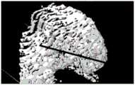
图2是在被测曲面的三维渲染图上重心G的法向量及器具实时姿态向量示意图;其中,虚线表示重心G的法向量,实线表示器具实时姿态向量。2 is a schematic diagram of the normal vector of the center of gravity G and the real-time attitude vector of the appliance on the three-dimensional rendering of the measured surface; wherein, the dotted line represents the normal vector of the center of gravity G, and the solid line represents the real-time attitude vector of the appliance.
具体实施方式Detailed ways
在本发明的描述中,需要理解的是,术语“上”、“下”、“内”、“外”等指示的方位或位置关系为基于附图所示的方位或位置关系,仅是为了便于描述本发明和简化描述,而不是指示或暗示所指的装置或元件必须具有特定的方位、以特定的方位构造和操作,因此不能理解为对本发明的限制。下面结合附图和实施例对本发明进行详细的描述。In the description of the present invention, it should be understood that the orientation or positional relationship indicated by the terms "upper", "lower", "inner", "outer", etc. is based on the orientation or positional relationship shown in the accompanying drawings, only for the purpose of It is convenient to describe the present invention and to simplify the description, rather than indicating or implying that the device or element referred to must have a particular orientation, be constructed and operate in a particular orientation, and therefore should not be construed as limiting the invention. The present invention will be described in detail below with reference to the accompanying drawings and embodiments.
如图1所示,本发明提供一种具有器具位姿导航的三维内窥镜,其包括摄像头1、光纤2、电磁传感器3(电磁式位置追踪器)和内窥镜探管6。摄像头1、光纤2和电磁传感器3均设置在内窥镜探管6内,且摄像头1、光纤2和电磁传感器3呈三角形排列布置,三者形成的三角形几何结构存储至上位机内。氦氖激光器与耦合镜设置在光纤的一端,氦氖激光器投射出的线激光4经耦合镜后由光纤2发出,投射在被测量曲面5上形成与被测量曲面5相一致的结构光,并由摄像头1采集该结构光后传输至上位机。电磁传感器3采集当前内窥镜的相对位置(3自由度)和姿态(3自由度)信息并传输至上位机,实现对摄像头1运动状态的跟踪。As shown in FIG. 1 , the present invention provides a three-dimensional endoscope with instrument posture navigation, which includes a
上述实施例中,摄像头1采用直径为2mm、型号为OVM6946的微型摄像头,其分辨率为16万像素,视角大小为120°,像面大小为400*400,30帧/秒,带防水功能,自带可调亮度LED光源。In the above embodiment, the
上述各实施例中,电磁传感器3采用直径为1mm的6自由度微型电磁传感器。例如,在本实施例中,电磁传感器3采用Micro-Sensor 1.8,其尺寸为:长17.3mm,直径1.8mm,厂家为Polhemus,USA。In the above embodiments, the
上述各实施例中,内窥镜探管6的直径为5-6mm。In the above embodiments, the diameter of the
上述各实施例中,摄像头1、光纤2和电磁传感器3之间的三角形排布结构,在内窥镜探管6内,电磁传感器3与摄像头1以平行的约束关系固定,且电磁传感器3必须位于摄像头1与光纤2之间;摄像头1与光纤2之间的几何连线及光纤2与电磁传感器3之间的几何连线呈八字形结构,以增加测量时的视差,从而提高测量的灵敏度和精度。In the above-mentioned embodiments, the triangular arrangement structure among the
基于上述三维内窥镜,本发明还提供一种具有器具位姿导航的三维内窥镜导航方法,其包括以下步骤:Based on the above-mentioned three-dimensional endoscope, the present invention also provides a three-dimensional endoscope navigation method with device posture navigation, which includes the following steps:
S1、将三维内窥镜的前端放置在距被测量表面一定距离处投射线激光4,采集被测量表面的结构光,并分别对相机平面(即图像平面)上的结构点进行提取和计算,获取曲面点云在内窥镜坐标系下的三维坐标值
优选的,一定距离可以为3-10mm;Preferably, the certain distance can be 3-10mm;
优选的,被测量表面的结构光可以采用摄像头1进行采集;Preferably, the structured light of the measured surface can be collected by the
其中,将相机的光轴定义为Z轴,即深度方向,相机上侧定义为X轴,右侧即为Y轴。则每个被检测出来的激光点在内窥镜坐标系下的三维坐标值为:Among them, the optical axis of the camera is defined as the Z axis, that is, the depth direction, the upper side of the camera is defined as the X axis, and the right side is the Y axis. Then the three-dimensional coordinate value of each detected laser point in the endoscope coordinate system is:


式中,B为基线长度,即光纤先端与相机先端的距离值;f为相机焦距;(x,y)为激光点在相机平面上的二维坐标值;(cx,cy)为相机平面的投影中心坐标。In the formula, B is the baseline length, that is, the distance between the fiber tip and the camera tip; f is the camera focal length; (x, y) is the two-dimensional coordinate value of the laser point on the camera plane; (cx , cy ) is the camera The projected center coordinates of the plane.
S2、将被测量表面在内窥镜坐标系上的坐标值转换到电磁传感器3,统一由电磁传感器坐标系表示。S2. Convert the coordinate value of the surface to be measured on the endoscope coordinate system to the
转换公式为:The conversion formula is:

式中,Rs为电磁传感器三维旋转矩阵,且有Rs=RzRyRx,Rz、Ry、Rx分别是绕Z轴、Y轴、X轴的旋转,均为3*3的矩阵;
S3、将电磁坐标系下的曲面点云渲染生成实体曲面。S3. Render the surface point cloud in the electromagnetic coordinate system to generate a solid surface.
优选的,采用Marching Cubes优化方法,在OpenGL下将电磁坐标系下的曲面点云渲染生成实体曲面;Preferably, the Marching Cubes optimization method is used to render the surface point cloud in the electromagnetic coordinate system under OpenGL to generate a solid surface;
实体曲面的生成方法具体步骤如下:The specific steps of the generation method of the solid surface are as follows:
S31、设相邻两个格子顶点分别是Ci和Ci-1,则点云格子的间隔参数t=Ci-Ci-1;S31, suppose that two adjacent lattice vertices are Ci and Ci-1 respectively, then the interval parameter t=Ci -Ci-1 of the point cloud lattice;
S32、计算以CiCi-1为边长的正方体内每一个点云在边长CiCi-1上的投影,如果投影点di在边长中点的左侧,则该点云配置给顶点Ci,否则配置给Ci-1;S32. Calculate the projection of each point cloud in the cube with Ci Ci-1 as the side length on the side length Ci Ci-1 . If the projected point di is on the left side of the midpoint of the side length, then the point Cloud is assigned to vertex Ci , otherwise assigned to Ci-1 ;
S33、根据顶点的分布状态,提取符合预设条件的三角形曲面,根据提取的三角形曲面生成8位二维数值的索引;S33, according to the distribution state of the vertices, extract the triangular surface that meets the preset condition, and generate the index of the 8-bit two-dimensional value according to the extracted triangular surface;
在一个正方体内,存在三角形的顶点给予二维数值1,否则赋予0;In a cube, the vertices of the existing triangles are given a two-dimensional value of 1, otherwise they are given 0;
S34、根据8位二维数值的索引获得曲面抽取的类型,进而完成曲面渲染,生成可视化曲面。S34. Obtain the type of surface extraction according to the index of the 8-bit two-dimensional value, and then complete the surface rendering to generate a visualized surface.
S4、计算生成实体曲面的所有曲面点云三维坐标的加权平均值,得到曲面的重心G的空间坐标值。S4. Calculate the weighted average of the three-dimensional coordinates of all the surface point clouds of the generated solid surface, and obtain the space coordinate value of the barycenter G of the surface.
S5、根据重心G的空间坐标值获取器具在当前曲面的实时姿态向量,完成导航。S5. Obtain the real-time attitude vector of the appliance on the current curved surface according to the space coordinate value of the center of gravity G, and complete the navigation.
具体方法包括以下步骤:The specific method includes the following steps:
S51、在以重心G为圆心,r为半径(优选r=1mm)的圆上搜索三个点云,当且仅当能够组成一个等边三角形时,存储这三个点云的三维坐标,记三角形的顶点分别为P1,P2,P3。S51. Search for three point clouds on a circle with the center of gravity G as the center of the circle and r as the radius (preferably r=1mm). If and only if an equilateral triangle can be formed, store the three-dimensional coordinates of the three point clouds, and record The vertices of the triangle are P1 , P2 , and P3 respectively.
S52、计算步骤S51中获得的等边三角形任意两边的向量积,求得等边三角形极小邻域内的法向量,则过重心G的法向量即为器具在当前曲面的实时姿态向量,此时重心G的坐标即为器具的当前位置。S52, calculate the vector product of any two sides of the equilateral triangle obtained in step S51, and obtain the normal vector in the minimal neighborhood of the equilateral triangle, then the normal vector passing through the center of gravity G is the real-time attitude vector of the appliance on the current surface, at this time The coordinate of the center of gravity G is the current position of the appliance.
S53、把步骤S52的法向量,以及器具实时姿态向量,通过OpenGL图像显示再现在显示屏上(如图2所示),完成导航。S53 , displaying the normal vector in step S52 and the real-time attitude vector of the appliance on the display screen through OpenGL image display (as shown in FIG. 2 ) to complete the navigation.
上述各实施例仅用于说明本发明,各部件的结构、尺寸、设置位置及形状都是可以有所变化的,在本发明技术方案的基础上,凡根据本发明原理对个别部件进行的改进和等同变换,均不应排除在本发明的保护范围之外。The above-mentioned embodiments are only used to illustrate the present invention, and the structure, size, setting position and shape of each component can be changed to some extent. and equivalent transformations shall not be excluded from the protection scope of the present invention.
Claims (10)
Translated fromChinese


Priority Applications (1)
| Application Number | Priority Date | Filing Date | Title |
|---|---|---|---|
| CN202010739975.1ACN111870211A (en) | 2020-07-28 | 2020-07-28 | A three-dimensional endoscope with instrument pose navigation and its navigation method |
Applications Claiming Priority (1)
| Application Number | Priority Date | Filing Date | Title |
|---|---|---|---|
| CN202010739975.1ACN111870211A (en) | 2020-07-28 | 2020-07-28 | A three-dimensional endoscope with instrument pose navigation and its navigation method |
Publications (1)
| Publication Number | Publication Date |
|---|---|
| CN111870211Atrue CN111870211A (en) | 2020-11-03 |
Family
ID=73201520
Family Applications (1)
| Application Number | Title | Priority Date | Filing Date |
|---|---|---|---|
| CN202010739975.1APendingCN111870211A (en) | 2020-07-28 | 2020-07-28 | A three-dimensional endoscope with instrument pose navigation and its navigation method |
Country Status (1)
| Country | Link |
|---|---|
| CN (1) | CN111870211A (en) |
Cited By (3)
| Publication number | Priority date | Publication date | Assignee | Title |
|---|---|---|---|---|
| CN113925441A (en)* | 2021-12-17 | 2022-01-14 | 极限人工智能有限公司 | Imaging method and imaging system based on endoscope |
| CN115281850A (en)* | 2022-08-12 | 2022-11-04 | 北京信息科技大学 | Apparatus attitude evaluation method based on hemispheric laser list method |
| JP2024031468A (en)* | 2022-08-26 | 2024-03-07 | 富士フイルム株式会社 | Image processing device, its operating method, and endoscope system |
Citations (4)
| Publication number | Priority date | Publication date | Assignee | Title |
|---|---|---|---|---|
| CN105030331A (en)* | 2015-04-24 | 2015-11-11 | 长春理工大学 | Position sensor and three-dimensional laparoscope camera calibration device and method |
| CN107485447A (en)* | 2017-08-09 | 2017-12-19 | 北京信息科技大学 | Utensil pose guider and method in a kind of art towards knee cartilage transplantation |
| CN208319312U (en)* | 2017-08-09 | 2019-01-04 | 北京信息科技大学 | Utensil pose navigation device in a kind of art towards knee cartilage transplantation |
| CN109620104A (en)* | 2019-01-10 | 2019-04-16 | 深圳市资福医疗技术有限公司 | Capsule endoscope and its localization method and system |
- 2020
- 2020-07-28CNCN202010739975.1Apatent/CN111870211A/enactivePending
Patent Citations (4)
| Publication number | Priority date | Publication date | Assignee | Title |
|---|---|---|---|---|
| CN105030331A (en)* | 2015-04-24 | 2015-11-11 | 长春理工大学 | Position sensor and three-dimensional laparoscope camera calibration device and method |
| CN107485447A (en)* | 2017-08-09 | 2017-12-19 | 北京信息科技大学 | Utensil pose guider and method in a kind of art towards knee cartilage transplantation |
| CN208319312U (en)* | 2017-08-09 | 2019-01-04 | 北京信息科技大学 | Utensil pose navigation device in a kind of art towards knee cartilage transplantation |
| CN109620104A (en)* | 2019-01-10 | 2019-04-16 | 深圳市资福医疗技术有限公司 | Capsule endoscope and its localization method and system |
Cited By (5)
| Publication number | Priority date | Publication date | Assignee | Title |
|---|---|---|---|---|
| CN113925441A (en)* | 2021-12-17 | 2022-01-14 | 极限人工智能有限公司 | Imaging method and imaging system based on endoscope |
| CN113925441B (en)* | 2021-12-17 | 2022-05-03 | 极限人工智能有限公司 | Imaging method and imaging system based on endoscope |
| CN115281850A (en)* | 2022-08-12 | 2022-11-04 | 北京信息科技大学 | Apparatus attitude evaluation method based on hemispheric laser list method |
| JP2024031468A (en)* | 2022-08-26 | 2024-03-07 | 富士フイルム株式会社 | Image processing device, its operating method, and endoscope system |
| JP7742079B2 (en) | 2022-08-26 | 2025-09-19 | 富士フイルム株式会社 | Image processing device, its operating method, and endoscope system |
Similar Documents
| Publication | Publication Date | Title |
|---|---|---|
| Fuchs et al. | Augmented reality visualization for laparoscopic surgery | |
| JP2019141620A (en) | Fixation point determination method and device on three-dimensional object | |
| US8248414B2 (en) | Multi-dimensional navigation of endoscopic video | |
| US7824328B2 (en) | Method and apparatus for tracking a surgical instrument during surgery | |
| US7945310B2 (en) | Surgical instrument path computation and display for endoluminal surgery | |
| CN106535806B (en) | The quantitative three-dimensional imaging of surgical scene from multiport visual angle | |
| KR101799281B1 (en) | Endoscope for minimally invasive surgery | |
| US9636188B2 (en) | System and method for 3-D tracking of surgical instrument in relation to patient body | |
| EP3076892B1 (en) | A medical optical tracking system | |
| US8885177B2 (en) | Medical wide field of view optical tracking system | |
| US20180116732A1 (en) | Real-time Three Dimensional Display of Flexible Needles Using Augmented Reality | |
| US20080071142A1 (en) | Visual navigation system for endoscopic surgery | |
| US20080071141A1 (en) | Method and apparatus for measuring attributes of an anatomical feature during a medical procedure | |
| CN111870211A (en) | A three-dimensional endoscope with instrument pose navigation and its navigation method | |
| JP2019511273A5 (en) | ||
| JP2017518147A (en) | Quantitative three-dimensional imaging of surgical scenes | |
| CN112184653B (en) | Binocular endoscope-based focus three-dimensional size measuring and displaying method | |
| US20110122229A1 (en) | Imaging System for Three-Dimensional Observation of an Operative Site | |
| JP2012525190A (en) | Real-time depth estimation from monocular endoscopic images | |
| CN109620408B (en) | Augmented reality operation navigation system calibration method based on electromagnetic positioning | |
| CN111035458A (en) | Intelligent auxiliary system for operation comprehensive vision and image processing method | |
| CN107485447B (en) | Device and method for navigating pose of surgical instrument for knee cartilage grafting | |
| CN113925441A (en) | Imaging method and imaging system based on endoscope | |
| Dimas et al. | Endoscopic single-image size measurements | |
| JPH11337845A (en) | Endoscope device |
Legal Events
| Date | Code | Title | Description |
|---|---|---|---|
| PB01 | Publication | ||
| PB01 | Publication | ||
| SE01 | Entry into force of request for substantive examination | ||
| SE01 | Entry into force of request for substantive examination | ||
| WD01 | Invention patent application deemed withdrawn after publication | ||
| WD01 | Invention patent application deemed withdrawn after publication | Application publication date:20201103 |