CN111867320A - cooling module - Google Patents
cooling moduleDownload PDFInfo
- Publication number
- CN111867320A CN111867320ACN201910383685.5ACN201910383685ACN111867320ACN 111867320 ACN111867320 ACN 111867320ACN 201910383685 ACN201910383685 ACN 201910383685ACN 111867320 ACN111867320 ACN 111867320A
- Authority
- CN
- China
- Prior art keywords
- heat
- heat dissipation
- section
- condensation
- dissipation module
- Prior art date
- Legal status (The legal status is an assumption and is not a legal conclusion. Google has not performed a legal analysis and makes no representation as to the accuracy of the status listed.)
- Withdrawn
Links
- 238000001816coolingMethods0.000titleclaimsdescription8
- 230000017525heat dissipationEffects0.000claimsabstractdescription92
- 230000005494condensationEffects0.000claimsabstractdescription69
- 238000009833condensationMethods0.000claimsabstractdescription69
- 238000001704evaporationMethods0.000claimsabstractdescription60
- 230000008020evaporationEffects0.000claimsabstractdescription60
- 230000000694effectsEffects0.000description16
- 239000007788liquidSubstances0.000description8
- 238000004519manufacturing processMethods0.000description8
- 230000008859changeEffects0.000description4
- 238000005259measurementMethods0.000description4
- 239000000463materialSubstances0.000description3
- 238000000034methodMethods0.000description3
- 238000005452bendingMethods0.000description2
- 239000012809cooling fluidSubstances0.000description2
- 238000010586diagramMethods0.000description2
- 239000007769metal materialSubstances0.000description2
- 238000009529body temperature measurementMethods0.000description1
- 239000004020conductorSubstances0.000description1
- 238000005520cutting processMethods0.000description1
- 230000006872improvementEffects0.000description1
- 230000007246mechanismEffects0.000description1
- 230000008569processEffects0.000description1
- 238000005096rolling processMethods0.000description1
- 238000007789sealingMethods0.000description1
- 229910000679solderInorganic materials0.000description1
Images


Classifications
- F—MECHANICAL ENGINEERING; LIGHTING; HEATING; WEAPONS; BLASTING
- F28—HEAT EXCHANGE IN GENERAL
- F28D—HEAT-EXCHANGE APPARATUS, NOT PROVIDED FOR IN ANOTHER SUBCLASS, IN WHICH THE HEAT-EXCHANGE MEDIA DO NOT COME INTO DIRECT CONTACT
- F28D15/00—Heat-exchange apparatus with the intermediate heat-transfer medium in closed tubes passing into or through the conduit walls ; Heat-exchange apparatus employing intermediate heat-transfer medium or bodies
- F28D15/02—Heat-exchange apparatus with the intermediate heat-transfer medium in closed tubes passing into or through the conduit walls ; Heat-exchange apparatus employing intermediate heat-transfer medium or bodies in which the medium condenses and evaporates, e.g. heat pipes
- F28D15/04—Heat-exchange apparatus with the intermediate heat-transfer medium in closed tubes passing into or through the conduit walls ; Heat-exchange apparatus employing intermediate heat-transfer medium or bodies in which the medium condenses and evaporates, e.g. heat pipes with tubes having a capillary structure
- H—ELECTRICITY
- H05—ELECTRIC TECHNIQUES NOT OTHERWISE PROVIDED FOR
- H05K—PRINTED CIRCUITS; CASINGS OR CONSTRUCTIONAL DETAILS OF ELECTRIC APPARATUS; MANUFACTURE OF ASSEMBLAGES OF ELECTRICAL COMPONENTS
- H05K7/00—Constructional details common to different types of electric apparatus
- H05K7/20—Modifications to facilitate cooling, ventilating, or heating
- H05K7/2029—Modifications to facilitate cooling, ventilating, or heating using a liquid coolant with phase change in electronic enclosures
- H05K7/20336—Heat pipes, e.g. wicks or capillary pumps
- F—MECHANICAL ENGINEERING; LIGHTING; HEATING; WEAPONS; BLASTING
- F28—HEAT EXCHANGE IN GENERAL
- F28D—HEAT-EXCHANGE APPARATUS, NOT PROVIDED FOR IN ANOTHER SUBCLASS, IN WHICH THE HEAT-EXCHANGE MEDIA DO NOT COME INTO DIRECT CONTACT
- F28D15/00—Heat-exchange apparatus with the intermediate heat-transfer medium in closed tubes passing into or through the conduit walls ; Heat-exchange apparatus employing intermediate heat-transfer medium or bodies
- F28D15/02—Heat-exchange apparatus with the intermediate heat-transfer medium in closed tubes passing into or through the conduit walls ; Heat-exchange apparatus employing intermediate heat-transfer medium or bodies in which the medium condenses and evaporates, e.g. heat pipes
- F28D15/0233—Heat-exchange apparatus with the intermediate heat-transfer medium in closed tubes passing into or through the conduit walls ; Heat-exchange apparatus employing intermediate heat-transfer medium or bodies in which the medium condenses and evaporates, e.g. heat pipes the conduits having a particular shape, e.g. non-circular cross-section, annular
- F—MECHANICAL ENGINEERING; LIGHTING; HEATING; WEAPONS; BLASTING
- F28—HEAT EXCHANGE IN GENERAL
- F28D—HEAT-EXCHANGE APPARATUS, NOT PROVIDED FOR IN ANOTHER SUBCLASS, IN WHICH THE HEAT-EXCHANGE MEDIA DO NOT COME INTO DIRECT CONTACT
- F28D15/00—Heat-exchange apparatus with the intermediate heat-transfer medium in closed tubes passing into or through the conduit walls ; Heat-exchange apparatus employing intermediate heat-transfer medium or bodies
- F28D15/02—Heat-exchange apparatus with the intermediate heat-transfer medium in closed tubes passing into or through the conduit walls ; Heat-exchange apparatus employing intermediate heat-transfer medium or bodies in which the medium condenses and evaporates, e.g. heat pipes
- F28D15/0266—Heat-exchange apparatus with the intermediate heat-transfer medium in closed tubes passing into or through the conduit walls ; Heat-exchange apparatus employing intermediate heat-transfer medium or bodies in which the medium condenses and evaporates, e.g. heat pipes with separate evaporating and condensing chambers connected by at least one conduit; Loop-type heat pipes; with multiple or common evaporating or condensing chambers
- H—ELECTRICITY
- H01—ELECTRIC ELEMENTS
- H01L—SEMICONDUCTOR DEVICES NOT COVERED BY CLASS H10
- H01L23/00—Details of semiconductor or other solid state devices
- H01L23/34—Arrangements for cooling, heating, ventilating or temperature compensation ; Temperature sensing arrangements
- H01L23/36—Selection of materials, or shaping, to facilitate cooling or heating, e.g. heatsinks
- H01L23/367—Cooling facilitated by shape of device
- H01L23/3672—Foil-like cooling fins or heat sinks
- H—ELECTRICITY
- H01—ELECTRIC ELEMENTS
- H01L—SEMICONDUCTOR DEVICES NOT COVERED BY CLASS H10
- H01L23/00—Details of semiconductor or other solid state devices
- H01L23/34—Arrangements for cooling, heating, ventilating or temperature compensation ; Temperature sensing arrangements
- H01L23/42—Fillings or auxiliary members in containers or encapsulations selected or arranged to facilitate heating or cooling
- H01L23/427—Cooling by change of state, e.g. use of heat pipes
- H—ELECTRICITY
- H05—ELECTRIC TECHNIQUES NOT OTHERWISE PROVIDED FOR
- H05K—PRINTED CIRCUITS; CASINGS OR CONSTRUCTIONAL DETAILS OF ELECTRIC APPARATUS; MANUFACTURE OF ASSEMBLAGES OF ELECTRICAL COMPONENTS
- H05K7/00—Constructional details common to different types of electric apparatus
- H05K7/20—Modifications to facilitate cooling, ventilating, or heating
- H05K7/2029—Modifications to facilitate cooling, ventilating, or heating using a liquid coolant with phase change in electronic enclosures
- H05K7/20309—Evaporators
- H—ELECTRICITY
- H05—ELECTRIC TECHNIQUES NOT OTHERWISE PROVIDED FOR
- H05K—PRINTED CIRCUITS; CASINGS OR CONSTRUCTIONAL DETAILS OF ELECTRIC APPARATUS; MANUFACTURE OF ASSEMBLAGES OF ELECTRICAL COMPONENTS
- H05K7/00—Constructional details common to different types of electric apparatus
- H05K7/20—Modifications to facilitate cooling, ventilating, or heating
- H05K7/2029—Modifications to facilitate cooling, ventilating, or heating using a liquid coolant with phase change in electronic enclosures
- H05K7/20318—Condensers
- H—ELECTRICITY
- H05—ELECTRIC TECHNIQUES NOT OTHERWISE PROVIDED FOR
- H05K—PRINTED CIRCUITS; CASINGS OR CONSTRUCTIONAL DETAILS OF ELECTRIC APPARATUS; MANUFACTURE OF ASSEMBLAGES OF ELECTRICAL COMPONENTS
- H05K7/00—Constructional details common to different types of electric apparatus
- H05K7/20—Modifications to facilitate cooling, ventilating, or heating
- H05K7/2039—Modifications to facilitate cooling, ventilating, or heating characterised by the heat transfer by conduction from the heat generating element to a dissipating body
- F—MECHANICAL ENGINEERING; LIGHTING; HEATING; WEAPONS; BLASTING
- F28—HEAT EXCHANGE IN GENERAL
- F28D—HEAT-EXCHANGE APPARATUS, NOT PROVIDED FOR IN ANOTHER SUBCLASS, IN WHICH THE HEAT-EXCHANGE MEDIA DO NOT COME INTO DIRECT CONTACT
- F28D21/00—Heat-exchange apparatus not covered by any of the groups F28D1/00 - F28D20/00
- F28D2021/0019—Other heat exchangers for particular applications; Heat exchange systems not otherwise provided for
- F28D2021/0028—Other heat exchangers for particular applications; Heat exchange systems not otherwise provided for for cooling heat generating elements, e.g. for cooling electronic components or electric devices
- F28D2021/0029—Heat sinks
- H—ELECTRICITY
- H01—ELECTRIC ELEMENTS
- H01L—SEMICONDUCTOR DEVICES NOT COVERED BY CLASS H10
- H01L21/00—Processes or apparatus adapted for the manufacture or treatment of semiconductor or solid state devices or of parts thereof
- H01L21/02—Manufacture or treatment of semiconductor devices or of parts thereof
- H01L21/04—Manufacture or treatment of semiconductor devices or of parts thereof the devices having potential barriers, e.g. a PN junction, depletion layer or carrier concentration layer
- H01L21/48—Manufacture or treatment of parts, e.g. containers, prior to assembly of the devices, using processes not provided for in a single one of the groups H01L21/18 - H01L21/326 or H10D48/04 - H10D48/07
- H01L21/4814—Conductive parts
- H01L21/4871—Bases, plates or heatsinks
- H01L21/4882—Assembly of heatsink parts
Landscapes
- Engineering & Computer Science (AREA)
- Microelectronics & Electronic Packaging (AREA)
- Physics & Mathematics (AREA)
- Thermal Sciences (AREA)
- General Engineering & Computer Science (AREA)
- Mechanical Engineering (AREA)
- Sustainable Development (AREA)
- Life Sciences & Earth Sciences (AREA)
- Computer Hardware Design (AREA)
- Power Engineering (AREA)
- General Physics & Mathematics (AREA)
- Condensed Matter Physics & Semiconductors (AREA)
- Materials Engineering (AREA)
- Chemical & Material Sciences (AREA)
- Cooling Or The Like Of Semiconductors Or Solid State Devices (AREA)
- Cooling Or The Like Of Electrical Apparatus (AREA)
Abstract
Translated fromChinese
Description
Translated fromChinese技术领域technical field
本发明涉及一种散热模块,尤其涉及一种以管路将蒸气与液体进行循环以达到散热的散热模块。The invention relates to a heat dissipation module, in particular to a heat dissipation module that circulates vapor and liquid through pipelines to achieve heat dissipation.
背景技术Background technique
良好的散热性能是确保电子产品有效工作的重要保障,电子产品的散热方式多种方式。例如:设置一个风扇加速气流交换或者通过管路使蒸气与液体进行循环散热。现有的散热模块具有多个热管,各热管中具有冷却流体,各热管弯折而概呈L型,使各热管的两端分别形成一蒸发端及一冷凝端,该多个热管的蒸发端连接一导热板,该多个热管的冷凝端则连接一鳍片组,且该多个热管的冷凝端各自独立而未相连通。Good heat dissipation performance is an important guarantee to ensure the effective work of electronic products. There are many ways to heat dissipation of electronic products. For example: setting a fan to speed up air exchange or circulating steam and liquid through pipes to dissipate heat. The existing heat dissipation module has a plurality of heat pipes, each heat pipe has a cooling fluid, and each heat pipe is bent to form an L shape, so that two ends of each heat pipe respectively form an evaporation end and a condensation end, and the evaporation ends of the plurality of heat pipes are formed. A heat conducting plate is connected, the condensation ends of the plurality of heat pipes are connected to a fin group, and the condensation ends of the plurality of heat pipes are independent and not connected.
然而,上述现有的散热模块,由于该多个热管的冷凝端各自独立而未相连通,使得各热管中的冷却流体无法在对位于该鳍片组的范围内彼此流通循环,除散热效率难以提升外,整体散热模块所需的热管数量也要比较多,因而需要进行较多次的裁切作业及对各热管两端的密封作业,导致制造成本难以下降。However, in the above-mentioned existing heat dissipation module, since the condensing ends of the plurality of heat pipes are independent and not connected, the cooling fluid in each heat pipe cannot circulate and circulate with each other within the range of the fin set, which is difficult to remove heat dissipation efficiency. In addition to the improvement, the number of heat pipes required for the overall heat dissipation module is also relatively large, so more cutting operations and sealing operations on both ends of each heat pipe are required, which makes it difficult to reduce the manufacturing cost.
有鉴于此,现有的散热模块确实仍有加以改善的必要。In view of this, the existing cooling module still needs to be improved.
发明内容SUMMARY OF THE INVENTION
为解决上述问题,本发明的目的在于提供一种散热模块,可以由一个热管的两端形成蒸发段,该热管的两端之间形成相连通的一冷凝段,使整个冷凝段可以彼此流通循环,可以提升散热效率及降低制造成本。In order to solve the above problems, the purpose of the present invention is to provide a heat dissipation module, which can form an evaporation section from both ends of a heat pipe, and form a connected condensation section between the two ends of the heat pipe, so that the entire condensation section can circulate and circulate with each other. , which can improve the heat dissipation efficiency and reduce the manufacturing cost.
本发明的一目的在于提供一种散热模块,可以使热管各处的温度可以较为稳定。An object of the present invention is to provide a heat dissipation module, which can make the temperature of the heat pipe more stable.
本发明的一目的在于提供一种散热模块,可以提升组装便利性。An object of the present invention is to provide a heat dissipation module, which can improve the convenience of assembly.
本发明的散热模块,包括:至少一个热管,该热管的第一端与第二端之间具有一个冷凝段,该热管的第一端与该冷凝段之间具有一个第一蒸发段,该热管的第二端与该冷凝段之间具有一个第二蒸发段,该冷凝段连通该第一蒸发段与该第二蒸发段;及一个散热鳍片组,位于该热管的冷凝段。The heat dissipation module of the present invention includes: at least one heat pipe with a condensation section between the first end and the second end of the heat pipe, a first evaporation section between the first end of the heat pipe and the condensation section, the heat pipe There is a second evaporation section between the second end of the heat pipe and the condensation section, the condensation section communicates with the first evaporation section and the second evaporation section; and a heat dissipation fin group located in the condensation section of the heat pipe.
据此,本发明的散热模块,利用至少一个热管的两端均形成蒸发段,而该热管的两端之间形成冷凝段,使得使整个冷凝段可以彼此流通循环,借此,具有可以提升散热效率及降低制造成本的效果。Accordingly, in the heat dissipation module of the present invention, both ends of at least one heat pipe are used to form an evaporation section, and a condensation section is formed between the two ends of the heat pipe, so that the entire condensation section can circulate and circulate with each other, thereby improving heat dissipation. Efficiency and the effect of reducing manufacturing costs.
本发明的散热模块还可以包括一个导热板,该导热板可热传导地连接该第一蒸发段及该第二蒸发段。如此,该导热板可以吸收热源,具有提升散热效率的效果。The heat dissipation module of the present invention may further include a heat conducting plate, which can be thermally conductively connected to the first evaporation section and the second evaporation section. In this way, the heat conducting plate can absorb the heat source, and has the effect of improving the heat dissipation efficiency.
其中,该冷凝段可以呈扁管状而具有相对的两个平面,该散热鳍片组至少与其中一个前述的平面相贴接。如此,可以增加该冷凝段与该散热鳍片组的接触面积,具有提升散热效率的效果。Wherein, the condensation section may be in the shape of a flat tube and have two opposite planes, and the heat dissipation fin group is attached to at least one of the aforementioned planes. In this way, the contact area between the condensation section and the heat dissipation fin group can be increased, which has the effect of improving the heat dissipation efficiency.
本发明的散热模块还可以包括一个连接器,该连接器连接该热管的第一端与第二端,使该连接器内部连通该第一蒸发段与该第二蒸发段。如此,该热管内部可以形成循环,具有提升散热效率的效果。The heat dissipation module of the present invention may further include a connector, which connects the first end and the second end of the heat pipe, so that the inside of the connector communicates with the first evaporation section and the second evaporation section. In this way, a circulation can be formed inside the heat pipe, which has the effect of improving the heat dissipation efficiency.
其中,该冷凝段形成有至少一个U形区,该U形区可以完全位于该散热鳍片组内。如此,该散热鳍片组可以覆盖整个冷凝段,具有提升散热效率的效果。Wherein, the condensation section is formed with at least one U-shaped area, and the U-shaped area can be completely located in the heat dissipation fin group. In this way, the heat dissipation fin group can cover the entire condensation section, which has the effect of improving the heat dissipation efficiency.
其中,该冷凝段形成有至少一个U形区,该U形区的局部可以凸伸出该散热鳍片组外。如此,可以选择由较小体积的该散热鳍片组连接该冷凝段,具有节省制造该散热鳍片组的材料成本的效果。Wherein, the condensation section is formed with at least one U-shaped area, and a part of the U-shaped area can protrude out of the heat dissipation fin group. In this way, the condensing section can be connected by the heat dissipation fin set with a smaller volume, which has the effect of saving the material cost of manufacturing the heat dissipation fin set.
其中,该热管的数量可以为单一个,该热管可以圈绕形成一个T形空间,使该冷凝段的两侧分别形成一个U形区。如此,该结构简易而便于制造,具有降低制造成本的效果。Wherein, the number of the heat pipe may be single, and the heat pipe may be wound to form a T-shaped space, so that two sides of the condensation section respectively form a U-shaped area. In this way, the structure is simple and easy to manufacture, and has the effect of reducing the manufacturing cost.
其中,该热管的数量可以为两个,两个热管可以分别圈绕形成一个靴形空间,各热管可以分别形成一个冷凝段,使两个冷凝段分别具有一个跟部及一个趾部,该两个冷凝段位于同一平面且以跟部相邻。如此,可以形成两个冷凝段,具有提升散热效率的效果。Wherein, the number of the heat pipes can be two, the two heat pipes can be respectively wound around to form a shoe-shaped space, and each heat pipe can form a condensing section respectively, so that the two condensing sections have a heel and a toe respectively. The condensing sections are located on the same plane and are adjacent to each other by their heels. In this way, two condensation sections can be formed, which has the effect of improving the heat dissipation efficiency.
其中,该热管的数量可以为多个,多个热管中的至少一个热管具有不同的外径。如此,可以依实际需求使用于不同的电子设备,具有可以广泛应用的效果。The number of the heat pipes may be multiple, and at least one of the multiple heat pipes has different outer diameters. In this way, it can be used in different electronic devices according to actual needs, and has the effect of being widely applicable.
其中,该热管的数量可以为多个,各热管可以圈绕形成一个T形空间或一个靴型空间,该多个热管的冷凝段分布于至少两个不同平面。如此,依据不同系统机构配置而作可以弹性调整,具有提升使用便利性的效果。The number of the heat pipes may be multiple, each heat pipe may be wound around to form a T-shaped space or a shoe-shaped space, and the condensation sections of the multiple heat pipes are distributed on at least two different planes. In this way, it can be flexibly adjusted according to the configuration of different system mechanisms, which has the effect of improving the convenience of use.
其中,该多个热管的第一蒸发段与第二蒸发段可以均位于同一平面。如此,该结构简易而便于组装,具有提升组装便利性的效果。Wherein, the first evaporation section and the second evaporation section of the plurality of heat pipes may be located on the same plane. In this way, the structure is simple and easy to assemble, and has the effect of improving the convenience of assembling.
其中,该热管的数量可以为两个,该散热鳍片组可以具有连接一个底层鳍片组的一个中间鳍片组与一个顶层鳍片组,该底层鳍片组连接其中一个前述的冷凝段,该顶层鳍片组连接另一个前述的冷凝段,该中间鳍片组同时连接该两个冷凝段。如此,可以通过三层鳍片组进行散热,具有提升散热效率的效果。Wherein, the number of the heat pipes may be two, the heat dissipation fin group may have a middle fin group connected to a bottom fin group and a top fin group, and the bottom fin group is connected to one of the aforementioned condensation sections, The top fin set is connected to another aforementioned condensation section, and the middle fin set is connected to the two condensation sections at the same time. In this way, heat dissipation can be carried out through the three-layer fin group, which has the effect of improving the heat dissipation efficiency.
附图说明Description of drawings
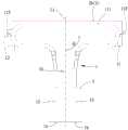
图1为本发明的第一实施例的分解立体图。FIG. 1 is an exploded perspective view of a first embodiment of the present invention.
图2为本发明的第一实施例的组合上视图。FIG. 2 is an assembled top view of the first embodiment of the present invention.
图3为本发明的第二实施例的组合上视图。FIG. 3 is an assembled top view of a second embodiment of the present invention.
图4为本发明的第三实施例的分解立体图。4 is an exploded perspective view of a third embodiment of the present invention.
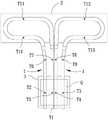
图5为 本发明的第三实施例热管的温度测量位置的示意图。FIG. 5 is a schematic diagram of the temperature measurement position of the heat pipe according to the third embodiment of the present invention.
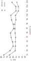
图6为现有技术与本发明的第三实施例的温度曲线图。FIG. 6 is a temperature curve diagram of the prior art and the third embodiment of the present invention.
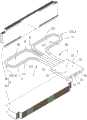
图7为本发明的第四实施例的分解立体图。7 is an exploded perspective view of a fourth embodiment of the present invention.
图8为本发明的第五实施例的分解立体图。8 is an exploded perspective view of a fifth embodiment of the present invention.
附图标记说明Description of reference numerals
(本发明)(this invention)
1 热管1 heat pipe
1a 第一端1a first end
1b 第二端1b second end
11 冷凝段11 Condensing section
111平面111 plane
112U形区112U shaped area
12 第一蒸发段12 The first evaporation stage
13 第二蒸发段13 The second evaporation section
2 散热鳍片组2 cooling fins
2a 底层鳍片组2a Bottom fin set
2b 顶层鳍片组2b top fin set
2c 中间鳍片组2c middle fin set
3 导热板3 Thermal plate
4 连接器4 connectors
H 跟部H heel
E 趾部E Toe
L1 蒸发轴线L1 evaporation axis
L2 冷凝轴线L2 condensation axis
S1 T形空间S1 T-shaped space
S2 靴形空间S2 boot space
Q 热源Q heat source
θ 角度。theta angle.
具体实施方式Detailed ways
为使本发明的上述及其他目的、特征及优点能更明显易懂,下文特列举本发明的较佳实施例,并配合附图,作详细说明如下:In order to make the above-mentioned and other objects, features and advantages of the present invention more obvious and easy to understand, the preferred embodiments of the present invention are enumerated below, and are described in detail as follows in conjunction with the accompanying drawings:
本发明全文所述方向性或其近似用语,例如“前”、“后”、“左”、“右”、“上(顶)”、“下(底)”、“内”、“外”、“侧面”等,主要是参考附图的方向,各方向性或其近似用语仅用以辅助说明及理解本发明的各实施例,并非用以限制本发明。Directionality or similar terms used throughout this disclosure, such as "front", "rear", "left", "right", "top (top)", "bottom (bottom)", "inside", "outside" , "side surface", etc., mainly refer to the directions of the drawings, and each directionality or its similar terms are only used to assist the description and understanding of the various embodiments of the present invention, and are not intended to limit the present invention.
本发明全文所记载的元件及构件使用“一”或“一个”的量词,仅是为了方便使用且提供本发明保护范围的通常意义;于本发明中应被解读为包括一个或至少一个,且单一的概念也包括复数的情况,除非其明显意指其他意思。The use of the quantifier "a" or "an" for the elements and components described throughout the present invention is only for convenience of use and provides the general meaning of the protection scope of the present invention; in the present invention, it should be construed as including one or at least one, and The singular concept also includes the plural, unless it is obvious that it is meant otherwise.
本发明全文所述“结合”、“组合”或“组装”等近似用语,主要包含连接后仍可不破坏构件地分离,或是连接后使构件不可分离等型态,为本领域中具有通常知识者可以依据欲相连的构件材质或组装需求予以选择的。Approximate terms such as "combined", "combined" or "assembled" mentioned in the whole text of the present invention mainly include the components that can be separated without destroying the components after being connected, or the components cannot be separated after being connected, which are common knowledge in the field. It can be selected according to the material of the components to be connected or the assembly requirements.
请参照图1所示,其为本发明的散热模块的第一实施例,其包括可直接或间接相连的至少一个热管1及一个散热鳍片组2。Please refer to FIG. 1 , which is a first embodiment of a heat dissipation module of the present invention, which includes at least one
该热管1可以选用导热材质所制成,且该热管1的内壁面较佳设置有规则或者不规则排列的毛细结构,该热管1内部具有工作液体,本实施例以单一个热管1来作说明。该热管1的第一端1a与第二端1b形成封闭,该热管1的第一端1a与第二端1b之间具有一个冷凝段11,该冷凝段11的形状本发明不加以限制,在本实施例中,可利用冲压或是滚压等技术而加以整平或压平成该冷凝段11,使该冷凝段11可以呈扁管状而具有相对的两个平面111。特别说明的是,该热管1长度较佳大于或等于该热管1外径的十九倍,使该热管1可以具有足够的弯折长度,且该热管1弯折圈绕为何种形状本发明不加以限制,例如:ㄇ形或M形,在本实施例中,该热管1圈绕形成一个T形空间S1,使该冷凝段11的两侧分别形成一个U形区112。The
请参照图1、图2所示,详言之,该热管1的第一端1a与该冷凝段11之间具有一个第一蒸发段12,该热管1的第二端1b与该冷凝段11之间具有一个第二蒸发段13,该第一蒸发段12与该第二蒸发段13分别连通该冷凝段11,意即,就单一个热管1而言,该热管1的头尾部位分别为该第一蒸发段12与该第二蒸发段13,该热管1的中间部位为该冷凝段11。其中,该第一蒸发段12与该第二蒸发段13可位于一个热源(图未绘示)处。此外,该第一蒸发段12与该第二蒸发段13的延伸方向可以形成一个蒸发轴线L1,该冷凝段11的该两个U形区112的延伸方向可以形成一个冷凝轴线L2,该冷凝轴线L2与该蒸发轴线L1之间具有一个角度θ,该角度θ较佳介于60~120度。Please refer to FIG. 1 and FIG. 2 . Specifically, there is a
该散热鳍片组2位于该热管1的冷凝段11,该散热鳍片组2可以采用导热系数高的金属材质制成。其中,该散热鳍片组2可以一体成型后,再结合该冷凝段11;在本实施例中,该散热鳍片组2具有一个底层鳍片组2a及一个顶层鳍片组2b,该底层鳍片组2a位于该冷凝段11下方,该顶层鳍片组2b位于该冷凝段11上方,该底层鳍片组2a与该顶层鳍片组2b可以与该两个平面111相贴接,以增加该冷凝段11与该散热鳍片组2的接触面积。另外,本实施例可以使该热管1的冷凝段11的该两个U形区112均完全位于该散热鳍片组2的范围内,此外,较佳可由一个散热风扇(图未绘示)对该散热鳍片组2吸收热气,从而可以把该散热鳍片组2的热气带走;或是对该散热鳍片组2吹送气流,从而可以使该散热鳍片组2的温度降低,以帮助该散热鳍片组2散热,使该热管1温度下降。The heat dissipation fin set 2 is located in the
本发明的散热模块还可以包括一个导热板3,该导热板3可以采用导热系数高的金属材质制成,使该导热板3可热传导地连接该第一蒸发段12及该第二蒸发段13。该导热板3连接该第一蒸发段12及该第二蒸发段13的方式,本发明不加以限制,在本实施例中,该第一蒸发段12及该第二蒸发段13穿伸于该导热板3内,并以锡膏焊接以形成可热传导地连接,使该热管1的第一端1a与第二端1b可以穿出或不穿出该导热板3。The heat-dissipating module of the present invention may further include a heat-conducting
请参照图2所示,通过前述结构,本发明散热模块使用时,可以将该导热板3装配于如电子设备等热源(图未绘示)处,该导热板3可以吸收热能,使液态的工作液体在该第一蒸发段12及该第二蒸发段13蒸发为气态,并流入该冷凝段11,通过该散热鳍片组2带走该冷凝段11的热能,使气态的工作液体在该冷凝段11降温冷凝而变回液态,同时通过该散热鳍片组2将热散发,达到使热源降温的效果,由于该热管1的第一蒸发段12与第二蒸发段13之间形成该冷凝段11,使得整个冷凝段11可以彼此流通循环,具有提升散热效率的效果。Referring to FIG. 2 , through the aforementioned structure, when the heat dissipation module of the present invention is used, the heat-conducting
请参照图3所示,其为本发明的散热模块的第二实施例,本发明的散热模块还可以包括一个连接器4,该连接器4的内壁面较佳设置有规则或者不规则排列的毛细结构。详言之,可以将该热管1的第一端1a与第二端1b进行裁切,使该热管1的第一端1a与第二端1b形成开放后,再以该连接器4连接于该热管1的第一端1a与第二端1b,使该连接器4内部可以连通该第一蒸发段12与该第二蒸发段13,使该热管1内部可以形成循环,可以更加提升散热效率。此外,当散热效率够好而不需太多鳍片时,也可以选择形成较小体积的该散热鳍片组2连接该冷凝段11,此时,使该U形区112的局部凸伸出该散热鳍片组2外,借此,可以节省制造该散热鳍片组2的材料成本。Please refer to FIG. 3 , which is the second embodiment of the heat dissipation module of the present invention. The heat dissipation module of the present invention may further include a
请参照图4所示,其为本发明的散热模块的第三实施例,该热管1的数量为两个,该两个热管1分别圈绕形成一个靴形空间S2,各热管1可以分别形成一个冷凝段11,因此,本实施例中总共具有两个冷凝段11,使该两个冷凝段11分别具有一个跟部H及一个趾部E,该趾部E即为上述的U形区112。该两个冷凝段11的设置方式可以为上下相叠或左右并排,在本实施例中,该两个冷凝段11位于同一平面且以跟部H相邻,该两个热管1的第一蒸发段12与第二蒸发段13则相间隔地并排于该导热板3,通过该两个热管1的设置,可以更加提升散热效率。Please refer to FIG. 4 , which is a third embodiment of the heat dissipation module of the present invention. The number of the
为力求实验精神,请参照图5所示,其为采用本发明的第三实施例的散热模块对一个热源Q进行散热的配置,并对该两个热管1的多处进行温度测量,其测量点分别为如图上所标示的T2、T3、T4、T5、T6、T7、T8、T9、T10、T11、T12、T13,而测量点T1对热源Q进行温度测量,其中,该测量点T1可以位于该导热板3与该热源Q之间。另外以相同条件测量替换成现有的热管型态的散热模块,并得到如图6所示的两个温度变化曲线。In order to strive for the spirit of experimentation, please refer to FIG. 5 , which is a configuration in which the heat dissipation module according to the third embodiment of the present invention is used to dissipate heat from one heat source Q, and the temperature of the two
由图6可知,具有本发明的热管型态的散热模块的各测量点温度确实都低于具有现有的热管型态的散热模块的各测量点温度,故本发明的散热模块确实可以提升散热效果。除此之外,值得注意的是,相较于具有现有的热管型态的散热模块的多个测量点之间具有较为明显的温度变化,具有本发明的热管型态的散热模块,其多个测量点之间的温度变化明显较稳定,可使得热管中的工作液体的相变化过程更为平稳,故本发明的散热模块确实可以提升散热效率。It can be seen from FIG. 6 that the temperature of each measurement point of the heat dissipation module with the heat pipe type of the present invention is indeed lower than the temperature of each measurement point of the heat dissipation module with the existing heat pipe type, so the heat dissipation module of the present invention can indeed improve the heat dissipation. Effect. In addition, it is worth noting that, compared with the heat dissipation module with the existing heat pipe type, there is a relatively obvious temperature change between multiple measurement points, and the heat dissipation module with the heat pipe type of the present invention has many The temperature change between the measurement points is obviously more stable, which can make the phase change process of the working liquid in the heat pipe more stable, so the heat dissipation module of the present invention can indeed improve the heat dissipation efficiency.
请参照图7所示,其为本发明的散热模块的第四实施例,该热管1的数量为多个,该多个热管1中的至少一个热管1可以具有不同的外径,本实施例的热管1以两个来做说明,各热管1圈绕形成一个T形空间S1,该多个热管1的冷凝段11可以选择分布于不同平面,而该多个热管1的第一蒸发段12与第二蒸发段13可以选择均位于同一平面。此外,该散热鳍片组2还可以具有位于该底层鳍片组2a与该顶层鳍片组2b之间的一个中间鳍片组2c,该底层鳍片组2a连接其中一个前述的冷凝段11,该顶层鳍片组2b连接另一个前述的冷凝段11,该中间鳍片组2c则同时连接该两个冷凝段11,借此,可以更加提升散热效率。Please refer to FIG. 7 , which is a fourth embodiment of the heat dissipation module of the present invention. The number of the
请参照图8所示,其为本发明的散热模块的第五实施例,该热管1的数量为四个,该四个热管1分别圈绕形成一个靴形空间S2,各热管1分别形成一个冷凝段11,因此,本实施例中总共具有四个冷凝段11,各冷凝段11分别具有一个跟部H及一个趾部E,该趾部E 即为上述的U形区112。该四个冷凝段11的设置方式可以为上下相叠或左右并排,在本实施例中,该四个冷凝段11的设置方式,为两两冷凝段11位于同一平面且以跟部H相邻,使该四个冷凝段11分别位于两个不同的平面,该四个热管1的第一蒸发段12与第二蒸发段13则相间隔地并排于该导热板3,通过该四个热管1的设置,可以更加提升散热效率。Please refer to FIG. 8 , which is the fifth embodiment of the heat dissipation module of the present invention. The number of the
综上所述,本发明的散热模块,利用至少一个热管的两端均形成蒸发段,而该热管的两端之间形成冷凝段,使得使整个冷凝段可以彼此流通循环,借此,具有可以提升散热效率及降低制造成本的效果。To sum up, in the heat dissipation module of the present invention, both ends of at least one heat pipe are used to form an evaporation section, and a condensation section is formed between the two ends of the heat pipe, so that the entire condensation section can circulate and circulate with each other. The effect of improving heat dissipation efficiency and reducing manufacturing cost.
Claims (12)
Translated fromChineseApplications Claiming Priority (2)
| Application Number | Priority Date | Filing Date | Title |
|---|---|---|---|
| TW108114922ATWI700472B (en) | 2019-04-29 | 2019-04-29 | Heat dissipation module |
| TW108114922 | 2019-04-29 |
Publications (1)
| Publication Number | Publication Date |
|---|---|
| CN111867320Atrue CN111867320A (en) | 2020-10-30 |
Family
ID=70694291
Family Applications (2)
| Application Number | Title | Priority Date | Filing Date |
|---|---|---|---|
| CN201910383685.5AWithdrawnCN111867320A (en) | 2019-04-29 | 2019-05-09 | cooling module |
| CN201920661802.5UActiveCN210610114U (en) | 2019-04-29 | 2019-05-09 | Heat radiation module |
Family Applications After (1)
| Application Number | Title | Priority Date | Filing Date |
|---|---|---|---|
| CN201920661802.5UActiveCN210610114U (en) | 2019-04-29 | 2019-05-09 | Heat radiation module |
Country Status (3)
| Country | Link |
|---|---|
| US (2) | US20200340755A1 (en) |
| CN (2) | CN111867320A (en) |
| TW (1) | TWI700472B (en) |
Cited By (3)
| Publication number | Priority date | Publication date | Assignee | Title |
|---|---|---|---|---|
| TWI766721B (en)* | 2021-06-09 | 2022-06-01 | 英業達股份有限公司 | Electronic device |
| CN115443025A (en)* | 2021-06-02 | 2022-12-06 | 英业达科技有限公司 | Electronic devices and cooling components |
| CN115443028A (en)* | 2021-06-03 | 2022-12-06 | 英业达科技有限公司 | Electronic device with a detachable cover |
Families Citing this family (3)
| Publication number | Priority date | Publication date | Assignee | Title |
|---|---|---|---|---|
| TWI700472B (en)* | 2019-04-29 | 2020-08-01 | 大陸商昆山廣興電子有限公司 | Heat dissipation module |
| CN213841858U (en)* | 2020-11-05 | 2021-07-30 | 亚浩电子五金塑胶(惠州)有限公司 | Heat pipe and heat radiation structure with same |
| TWI795198B (en)* | 2022-01-28 | 2023-03-01 | 營邦企業股份有限公司 | Rapid heat dissipation device |
Citations (7)
| Publication number | Priority date | Publication date | Assignee | Title |
|---|---|---|---|---|
| CN1884954A (en)* | 2005-06-24 | 2006-12-27 | 鸿富锦精密工业(深圳)有限公司 | Heat pipe |
| CN202565654U (en)* | 2012-04-28 | 2012-11-28 | 昆山巨仲电子有限公司 | Heat dissipation device and heat conduction structure thereof |
| CN102909522A (en)* | 2011-08-01 | 2013-02-06 | 讯凯国际股份有限公司 | Heat pipe and manufacturing method thereof |
| TWM450187U (en)* | 2012-10-25 | 2013-04-01 | Cooling House Co Ltd | Circulation type thermosyphon heat dissipation device |
| CN107166564A (en)* | 2017-06-20 | 2017-09-15 | 珠海格力电器股份有限公司 | Heat pipe heat exchanger, air conditioner control radiating assembly, air conditioner outdoor unit and air conditioner |
| CN208124946U (en)* | 2018-03-29 | 2018-11-20 | 广东努谢尔环境科技有限公司 | Array Microchannel Heat Pipe Heat Exchanger |
| CN210610114U (en)* | 2019-04-29 | 2020-05-22 | 昆山广兴电子有限公司 | Heat radiation module |
Family Cites Families (7)
| Publication number | Priority date | Publication date | Assignee | Title |
|---|---|---|---|---|
| CN1220028C (en)* | 2001-06-22 | 2005-09-21 | 李嘉豪 | Loop type heat pipe heat exchange assembly |
| RU2297661C2 (en)* | 2005-07-29 | 2007-04-20 | Институт теплофизики Уро РАН | Passive cooling system for desktop computers |
| JP4762120B2 (en)* | 2006-11-24 | 2011-08-31 | 株式会社東芝 | Electronic equipment, cooling device |
| US20100101763A1 (en)* | 2008-10-27 | 2010-04-29 | Meng-Cheng Huang | Thin heat dissipating apparatus |
| TW201527702A (en)* | 2014-01-15 | 2015-07-16 | Asia Vital Components Co Ltd | Heat pipe structure and thermal module using same |
| JP6117288B2 (en)* | 2015-07-14 | 2017-04-19 | 古河電気工業株式会社 | Cooling system |
| JP6606267B1 (en)* | 2018-12-28 | 2019-11-13 | 古河電気工業株式会社 | heatsink |
- 2019
- 2019-04-29TWTW108114922Apatent/TWI700472B/enactive
- 2019-05-09CNCN201910383685.5Apatent/CN111867320A/ennot_activeWithdrawn
- 2019-05-09CNCN201920661802.5Upatent/CN210610114U/enactiveActive
- 2020
- 2020-01-02USUS16/732,535patent/US20200340755A1/ennot_activeAbandoned
- 2022
- 2022-01-24USUS17/582,771patent/US20220146206A1/ennot_activeAbandoned
Patent Citations (7)
| Publication number | Priority date | Publication date | Assignee | Title |
|---|---|---|---|---|
| CN1884954A (en)* | 2005-06-24 | 2006-12-27 | 鸿富锦精密工业(深圳)有限公司 | Heat pipe |
| CN102909522A (en)* | 2011-08-01 | 2013-02-06 | 讯凯国际股份有限公司 | Heat pipe and manufacturing method thereof |
| CN202565654U (en)* | 2012-04-28 | 2012-11-28 | 昆山巨仲电子有限公司 | Heat dissipation device and heat conduction structure thereof |
| TWM450187U (en)* | 2012-10-25 | 2013-04-01 | Cooling House Co Ltd | Circulation type thermosyphon heat dissipation device |
| CN107166564A (en)* | 2017-06-20 | 2017-09-15 | 珠海格力电器股份有限公司 | Heat pipe heat exchanger, air conditioner control radiating assembly, air conditioner outdoor unit and air conditioner |
| CN208124946U (en)* | 2018-03-29 | 2018-11-20 | 广东努谢尔环境科技有限公司 | Array Microchannel Heat Pipe Heat Exchanger |
| CN210610114U (en)* | 2019-04-29 | 2020-05-22 | 昆山广兴电子有限公司 | Heat radiation module |
Cited By (3)
| Publication number | Priority date | Publication date | Assignee | Title |
|---|---|---|---|---|
| CN115443025A (en)* | 2021-06-02 | 2022-12-06 | 英业达科技有限公司 | Electronic devices and cooling components |
| CN115443028A (en)* | 2021-06-03 | 2022-12-06 | 英业达科技有限公司 | Electronic device with a detachable cover |
| TWI766721B (en)* | 2021-06-09 | 2022-06-01 | 英業達股份有限公司 | Electronic device |
Also Published As
| Publication number | Publication date |
|---|---|
| TWI700472B (en) | 2020-08-01 |
| US20200340755A1 (en) | 2020-10-29 |
| US20220146206A1 (en) | 2022-05-12 |
| CN210610114U (en) | 2020-05-22 |
| TW202040079A (en) | 2020-11-01 |
Similar Documents
| Publication | Publication Date | Title |
|---|---|---|
| CN111867320A (en) | cooling module | |
| JP4391366B2 (en) | Heat sink with heat pipe and method of manufacturing the same | |
| CN106033749A (en) | Parallel Parallel Microchannel Multi-Chip Heat Sink | |
| CN100456461C (en) | Heat sink of heat pipe | |
| TWI686130B (en) | Cooling module | |
| CN111010847B (en) | A soaking plate type heat sink | |
| CN215421387U (en) | Heat radiation module | |
| CN108106473B (en) | Vapor-liquid phase flow heat transfer module | |
| US10578368B2 (en) | Two-phase fluid heat transfer structure | |
| CN101316495B (en) | Heat sink assembly | |
| CN206909027U (en) | Radiator and cooling system | |
| CN114001336B (en) | High-power heat source heat dissipation device and structure thereof | |
| TW201723413A (en) | Cooling module | |
| JP5624771B2 (en) | Heat pipe and heat sink with heat pipe | |
| CN110198611B (en) | Heat sink device | |
| TWM628154U (en) | Air-liquid dual cooling radiator for memory modules | |
| CN108282983B (en) | Two-phase flow heat transfer structure | |
| TWI484895B (en) | Heat dissipation device | |
| TW202238063A (en) | Heat dissipation module | |
| CN108323099B (en) | Fin type heat pipe coupling radiator | |
| TWI640740B (en) | Vapor-liquid flow heat transfer module | |
| CN207706620U (en) | Two-phase flow heat transfer structure | |
| JP2016205745A (en) | Heat pipe type heat sink | |
| CN221887021U (en) | A heat dissipation device with high thermal conductivity | |
| CN220897076U (en) | Composite heat dissipation components |
Legal Events
| Date | Code | Title | Description |
|---|---|---|---|
| PB01 | Publication | ||
| PB01 | Publication | ||
| SE01 | Entry into force of request for substantive examination | ||
| SE01 | Entry into force of request for substantive examination | ||
| WW01 | Invention patent application withdrawn after publication | Application publication date:20201030 | |
| WW01 | Invention patent application withdrawn after publication |