CN111856430B - A double-layer comb-driven MEMS scanning mirror for laser radar and its preparation method - Google Patents
A double-layer comb-driven MEMS scanning mirror for laser radar and its preparation methodDownload PDFInfo
- Publication number
- CN111856430B CN111856430BCN202010737221.2ACN202010737221ACN111856430BCN 111856430 BCN111856430 BCN 111856430BCN 202010737221 ACN202010737221 ACN 202010737221ACN 111856430 BCN111856430 BCN 111856430B
- Authority
- CN
- China
- Prior art keywords
- layer
- comb teeth
- frame
- silicon
- comb
- Prior art date
- Legal status (The legal status is an assumption and is not a legal conclusion. Google has not performed a legal analysis and makes no representation as to the accuracy of the status listed.)
- Active
Links
- 238000002360preparation methodMethods0.000titledescription3
- XUIMIQQOPSSXEZ-UHFFFAOYSA-NSiliconChemical compound[Si]XUIMIQQOPSSXEZ-UHFFFAOYSA-N0.000claimsdescription53
- 229910052710siliconInorganic materials0.000claimsdescription53
- 239000010703siliconSubstances0.000claimsdescription53
- 239000011521glassSubstances0.000claimsdescription28
- 238000000034methodMethods0.000claimsdescription28
- 238000005516engineering processMethods0.000claimsdescription24
- 244000126211Hericium coralloidesSpecies0.000claimsdescription22
- VYPSYNLAJGMNEJ-UHFFFAOYSA-NSilicium dioxideChemical compoundO=[Si]=OVYPSYNLAJGMNEJ-UHFFFAOYSA-N0.000claimsdescription22
- 229910052814silicon oxideInorganic materials0.000claimsdescription22
- 230000008569processEffects0.000claimsdescription17
- 239000000758substrateSubstances0.000claimsdescription16
- 238000000708deep reactive-ion etchingMethods0.000claimsdescription12
- 239000002184metalSubstances0.000claimsdescription9
- 229910052751metalInorganic materials0.000claimsdescription9
- 238000012545processingMethods0.000claimsdescription8
- 238000005566electron beam evaporationMethods0.000claimsdescription6
- 238000002834transmittanceMethods0.000claimsdescription6
- 238000004519manufacturing processMethods0.000claimsdescription4
- PCHJSUWPFVWCPO-UHFFFAOYSA-NgoldChemical compound[Au]PCHJSUWPFVWCPO-UHFFFAOYSA-N0.000claimsdescription3
- 239000010931goldSubstances0.000claimsdescription3
- 229910052737goldInorganic materials0.000claimsdescription3
- 238000001755magnetron sputter depositionMethods0.000claimsdescription3
- 238000001020plasma etchingMethods0.000claimsdescription3
- 239000002210silicon-based materialSubstances0.000claimsdescription3
- 238000005530etchingMethods0.000claims3
- 238000000151depositionMethods0.000claims2
- 238000001259photo etchingMethods0.000claims2
- 238000004544sputter depositionMethods0.000claims1
- 239000010410layerSubstances0.000description121
- 238000010586diagramMethods0.000description19
- 210000001520combAnatomy0.000description10
- 239000010408filmSubstances0.000description10
- 230000009471actionEffects0.000description8
- 238000000206photolithographyMethods0.000description4
- 238000011161developmentMethods0.000description3
- 238000006073displacement reactionMethods0.000description3
- 230000000694effectsEffects0.000description2
- 239000000463materialSubstances0.000description2
- 239000007769metal materialSubstances0.000description2
- 238000004806packaging method and processMethods0.000description2
- 230000004044responseEffects0.000description2
- 230000035945sensitivityEffects0.000description2
- 239000002356single layerSubstances0.000description2
- 230000009286beneficial effectEffects0.000description1
- 230000005684electric fieldEffects0.000description1
- 238000004377microelectronicMethods0.000description1
- 238000012986modificationMethods0.000description1
- 230000004048modificationEffects0.000description1
- 238000011112process operationMethods0.000description1
- 238000012360testing methodMethods0.000description1
- 239000010409thin filmSubstances0.000description1
- 238000013519translationMethods0.000description1
Images


Classifications
- G—PHYSICS
- G01—MEASURING; TESTING
- G01S—RADIO DIRECTION-FINDING; RADIO NAVIGATION; DETERMINING DISTANCE OR VELOCITY BY USE OF RADIO WAVES; LOCATING OR PRESENCE-DETECTING BY USE OF THE REFLECTION OR RERADIATION OF RADIO WAVES; ANALOGOUS ARRANGEMENTS USING OTHER WAVES
- G01S7/00—Details of systems according to groups G01S13/00, G01S15/00, G01S17/00
- G01S7/48—Details of systems according to groups G01S13/00, G01S15/00, G01S17/00 of systems according to group G01S17/00
- G01S7/481—Constructional features, e.g. arrangements of optical elements
- G01S7/4817—Constructional features, e.g. arrangements of optical elements relating to scanning
- B—PERFORMING OPERATIONS; TRANSPORTING
- B81—MICROSTRUCTURAL TECHNOLOGY
- B81B—MICROSTRUCTURAL DEVICES OR SYSTEMS, e.g. MICROMECHANICAL DEVICES
- B81B7/00—Microstructural systems; Auxiliary parts of microstructural devices or systems
- B81B7/02—Microstructural systems; Auxiliary parts of microstructural devices or systems containing distinct electrical or optical devices of particular relevance for their function, e.g. microelectro-mechanical systems [MEMS]
- G—PHYSICS
- G02—OPTICS
- G02B—OPTICAL ELEMENTS, SYSTEMS OR APPARATUS
- G02B26/00—Optical devices or arrangements for the control of light using movable or deformable optical elements
- G02B26/08—Optical devices or arrangements for the control of light using movable or deformable optical elements for controlling the direction of light
- G02B26/0816—Optical devices or arrangements for the control of light using movable or deformable optical elements for controlling the direction of light by means of one or more reflecting elements
- G02B26/0833—Optical devices or arrangements for the control of light using movable or deformable optical elements for controlling the direction of light by means of one or more reflecting elements the reflecting element being a micromechanical device, e.g. a MEMS mirror, DMD
- G02B26/0841—Optical devices or arrangements for the control of light using movable or deformable optical elements for controlling the direction of light by means of one or more reflecting elements the reflecting element being a micromechanical device, e.g. a MEMS mirror, DMD the reflecting element being moved or deformed by electrostatic means
- G—PHYSICS
- G02—OPTICS
- G02B—OPTICAL ELEMENTS, SYSTEMS OR APPARATUS
- G02B26/00—Optical devices or arrangements for the control of light using movable or deformable optical elements
- G02B26/08—Optical devices or arrangements for the control of light using movable or deformable optical elements for controlling the direction of light
- G02B26/10—Scanning systems
- Y—GENERAL TAGGING OF NEW TECHNOLOGICAL DEVELOPMENTS; GENERAL TAGGING OF CROSS-SECTIONAL TECHNOLOGIES SPANNING OVER SEVERAL SECTIONS OF THE IPC; TECHNICAL SUBJECTS COVERED BY FORMER USPC CROSS-REFERENCE ART COLLECTIONS [XRACs] AND DIGESTS
- Y02—TECHNOLOGIES OR APPLICATIONS FOR MITIGATION OR ADAPTATION AGAINST CLIMATE CHANGE
- Y02A—TECHNOLOGIES FOR ADAPTATION TO CLIMATE CHANGE
- Y02A90/00—Technologies having an indirect contribution to adaptation to climate change
- Y02A90/10—Information and communication technologies [ICT] supporting adaptation to climate change, e.g. for weather forecasting or climate simulation
Landscapes
- Physics & Mathematics (AREA)
- Engineering & Computer Science (AREA)
- General Physics & Mathematics (AREA)
- Optics & Photonics (AREA)
- Computer Networks & Wireless Communication (AREA)
- Radar, Positioning & Navigation (AREA)
- Remote Sensing (AREA)
- Computer Hardware Design (AREA)
- Microelectronics & Electronic Packaging (AREA)
- Mechanical Light Control Or Optical Switches (AREA)
- Micromachines (AREA)
Abstract
Translated fromChinese
Description
Translated fromChinese技术领域technical field
本发明涉及微机电技术领域,具体涉及一种用于激光雷达的双层梳齿驱动MEMS扫描镜及制备方法。The invention relates to the field of micro-electromechanical technology, in particular to a double-layer comb-driven MEMS scanning mirror for laser radar and a preparation method.
背景技术Background technique
随着各种先进器件的不断发展,激光雷达逐渐向低成本、低功耗、小型化和便捷式应用方向发展,特别是MEMS技术的发展带动了MEMS扫描镜的发展。用于激光雷达系统的MEMS扫描镜要求其扫描角度大,驱动电压低,有效的降低系统的功耗,且工艺简单易于集成。With the continuous development of various advanced devices, lidar is gradually developing towards low cost, low power consumption, miniaturization and convenient application. In particular, the development of MEMS technology has driven the development of MEMS scanning mirrors. The MEMS scanning mirror used in the lidar system requires a large scanning angle, low driving voltage, effectively reducing the power consumption of the system, and the process is simple and easy to integrate.
MEMS扫描镜主要依靠微驱动器来推动可活动镜面产生转动或平动,从而改变入射光的传播方向。MEMS扫描镜可根据其驱动方式分为电磁驱动、电热驱动、压电驱动和静电驱动四类。其中,电磁驱动功耗很高,并且在包装反射镜时始终需要在外部施加磁场,无法实现系统的微型化。电热驱动其响应缓慢、功耗高以及对环境温度敏感等因素限制了MEMS扫描镜的性能。电压驱动的扫描镜响应速度快,但是难以制造高质量的压电薄膜。然而,静电驱动的MEMS扫描镜具有体积小、功耗低、可扩展性高,响应速度快以及与集成电路的良好兼容性等优点,能够在大位移状态下实现高精度的位置控制,从各方面特性上看更适合应用于激光雷达领域。2017年Yanjun Fan和Can Cui等人提出了一种新型的静电垂直梳状驱动扫描微镜的制造和测试,制作的反射镜在95 VPP正弦信号下可以实现±10.8°的机械扫描角,该器件的谐振频率为393 Hz。MEMS scanning mirrors mainly rely on micro-actuators to drive the movable mirror to produce rotation or translation, thereby changing the propagation direction of incident light. MEMS scanning mirrors can be divided into four types according to their driving methods: electromagnetic drive, electrothermal drive, piezoelectric drive and electrostatic drive. Among them, the electromagnetic drive consumes a lot of power, and it is always necessary to apply an external magnetic field when packaging the mirror, which makes it impossible to miniaturize the system. Factors such as slow response, high power consumption, and sensitivity to ambient temperature of the electrothermal drive limit the performance of the MEMS scanning mirror. Voltage-driven scanning mirrors respond quickly, but it is difficult to fabricate high-quality piezoelectric films. However, the electrostatically driven MEMS scanning mirror has the advantages of small size, low power consumption, high scalability, fast response speed, and good compatibility with integrated circuits, and can achieve high-precision position control in a large displacement state, from various In terms of characteristics, it is more suitable for application in the field of lidar. In 2017, Yanjun Fan and Can Cui et al. proposed the manufacture and testing of a new type of electrostatic vertical comb-driven scanning micromirror. The fabricated mirror can achieve a mechanical scanning angle of ±10.8° under a 95 VPP sinusoidal signal. The device The resonant frequency is 393 Hz.
然而,现有的MEMS扫描镜主要还存在以下缺点:(1)驱动电压较高,扫描频率与扭转角度较小,无法有效的降低激光雷达功耗。(2)扫描镜结构和加工工艺复杂,加工成本高。However, the existing MEMS scanning mirrors mainly have the following disadvantages: (1) The driving voltage is high, the scanning frequency and the torsion angle are small, and the power consumption of the lidar cannot be effectively reduced. (2) The structure and processing technology of the scanning mirror are complicated, and the processing cost is high.
发明内容Contents of the invention
针对现有用于激光雷达的MEMS扫描镜存在的不足,本发明提供一种用于激光雷达的双层梳齿驱动MEMS扫描镜及制备方法,解决了现有技术中存在的驱动电压较高,扫描频率与扭转角度较小等问题。Aiming at the shortcomings of existing MEMS scanning mirrors used for laser radar, the present invention provides a double-layer comb-driven MEMS scanning mirror for laser radar and its preparation method, which solves the problem of high driving voltage and high scanning voltage in the prior art. Problems such as frequency and torsion angle are small.
本发明为了解决以上技术问题采用以下技术方案:The present invention adopts the following technical solutions in order to solve the above technical problems:
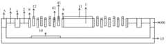
一种用于激光雷达的双层梳齿驱动MEMS扫描镜,包括透明的玻璃盖帽16、旋转扫描镜本体和硅基底15;A double-layer comb-driven MEMS scanning mirror for lidar, including a
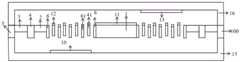
所述旋转扫描镜本体为方形的结构层硅材料,且包括方形的微镜1、第一S型扭转梁2、第二S型扭转梁3、长方形的内层框架4和长方形的外层框架5;The body of the rotating scanning mirror is a square structural layer silicon material, and includes a
所述外层框架5同轴套设在内层框架4外,且内层框架4的两端分别通过第一S型扭转梁2连接着外层框架5;The
所述微镜1两端均依次通过直连接梁6、第二S型扭转梁3对应连接着内层框架4,使得微镜1活动安装在内层框架4的中部;Both ends of the
以外层框架5的中心为原点,外层框架5的长度方向为y轴、宽度方向为x轴,所述第一S型扭转梁2的旋转轴、第二S型扭转梁3的旋转轴和直连接梁6均位于y轴上;The center of the
所述每个直连接梁6的两侧均匀布设有驱动梳齿61;所述内层框架4每个侧框的内侧均匀布设有内层可动梳齿41、每个侧框的外侧均匀布设有外层可动梳齿42;所述外层框架5每个侧框的内侧均匀布设有固定梳齿51;The two sides of each straight connecting
所述外层可动梳齿42和固定梳齿51交替布置,且高低交错;所述内层可动梳齿41和驱动梳齿61交替布置,且高低交错;The outer
所述微镜1的上表面设有微镜反射层11,所述每个驱动梳齿61、内层可动梳齿41、外层可动梳齿42和固定梳齿51外均包裹梳齿电极层12。The upper surface of the
所述玻璃盖帽16的下底面布设有上电极13,所述硅基底15的上底面布设有下电极10,且上电极13对应着y轴方向一侧的外层框架5,下电极10对应着y轴方向另一侧的外层框架5;The lower bottom surface of the
所述玻璃盖帽16、外层框架5和硅基底15依次键合,形成封闭的活动腔,所述微镜1可在活动腔内旋动。The
工作时,通过向梳齿电极层12、上电极13和下电极10施加驱动电压,使得所述微镜1可在活动腔内旋动。During operation, the
进一步,所述相邻驱动梳齿61之间的间隔距离、相邻固定梳齿51之间的间隔距离、相邻内层可动梳齿41之间的间隔距离和相邻外层可动梳齿42之间的间隔距离均相等。Further, the distance between the adjacent
进一步,所述下电极10、微镜反射层11和梳齿电极层12均为金的金属材料,上电极13为掺Sn的ITO薄膜,且透射率达到90%以上,所述玻璃盖帽16为K9玻璃材料制成,且透射率达到99%。Further, the
本发明还包括一种用于激光雷达的双层梳齿驱动MEMS扫描镜的制备方法,采用体硅加工工艺,包括以下步骤:The present invention also includes a method for preparing a double-layer comb-driven MEMS scanning mirror for laser radar, which adopts bulk silicon processing technology and includes the following steps:
步骤(1):取一片双抛SOI晶片,且包括顶硅层100、中间氧化硅层101、底硅层102,在顶硅层100上采用深反应离子刻蚀并显露出微镜1、直连接梁6、第一S型扭转梁2、第二S型扭转梁3、内层框架4、外层框架5、驱动梳齿61、内层可动梳齿41、外层可动梳齿42和固定梳齿51;使得驱动梳齿61和内层可动梳齿41交替布置、外层可动梳齿42和固定梳齿51交替布置;Step (1): Take a double-polished SOI wafer, including a
步骤(2):在步骤1的基础上采用一张掩膜板光刻,减薄内层可动梳齿41和固定梳齿51上的顶硅层100;Step (2): On the basis of
步骤(3):在步骤2的基础上采用一张掩膜板光刻,减薄第一S型扭转梁2和第一S型扭转梁3上的顶硅层100;Step (3): On the basis of
步骤(4):取一片硅片15腐蚀出下凹槽,得到硅基底15,采用电子束蒸发工艺在下凹槽的表面沉积金属薄膜,形成下电极10;Step (4): Take a piece of
步骤(5):将步骤3得到的双抛SOI晶片倒置,并和硅基底15进行硅-硅键合;Step (5): Invert the double-throw SOI wafer obtained in
步骤(6):采用深反应离子刻蚀技术将步骤5的双抛SOI晶片的底硅层102全部去掉,露出氧化硅层101;Step (6): Using deep reactive ion etching technology to remove all the
步骤(7):在氧化硅层101上采用反应离子刻蚀技术,将外层可动梳齿42和驱动梳齿61上的氧化硅层101去掉,保留直连接梁6、第一S型扭转梁2和第二S型扭转梁3、固定梳齿51、内层可动梳齿41、内层框架4、外层框架5和微镜1上的氧化硅层101;Step (7): Reactive ion etching technology is used on the
步骤(8):在步骤7的基础上采用深反应离子刻蚀技术,把外层可动梳齿42和驱动梳齿61上的顶硅层100刻蚀减薄,使得外层可动梳齿42和固定梳齿51高低交错布置,驱动梳齿61和内层可动梳齿41高低交错布置;Step (8): On the basis of step 7, use deep reactive ion etching technology to etch and thin the
步骤(9):在步骤8的基础上采用深反应离子刻蚀技术,刻蚀掉直连接梁6、第一S型扭转梁2、第二S型扭转梁3、固定梳齿51、内层可动梳齿41、内层框架4、外层框架5和微镜1上的氧化硅层101;Step (9): On the basis of step 8, use deep reactive ion etching technology to etch away the straight connecting
步骤(10):在步骤9的基础上采用电子束蒸发工艺,利用掩膜板在微镜1的上表面沉积一层金属薄膜,为微镜反射层11,Step (10): on the basis of step 9, using an electron beam evaporation process, using a mask plate to deposit a layer of metal film on the upper surface of the
在内层可动梳齿41表面、外层可动梳齿42表面、驱动梳齿61表面和固定梳齿51表面均沉积一层金属薄膜,为梳齿电极层12;A layer of metal film is deposited on the surface of the
步骤(11):取一片K9玻璃采用HF溶液刻蚀出上凹槽,得到玻璃盖帽16,采用磁控溅射技术在上凹槽的表面溅射一层掺Sn的 ITO薄膜,形成上电极13;Step (11): Take a piece of K9 glass and use HF solution to etch the upper groove to obtain the
步骤(12):将玻璃盖帽16和步骤10得到的结构进行硅-玻璃阳极键合;使得上凹槽和下凹槽通过键合形成封闭的活动腔,所述微镜1可在活动腔内旋动。Step (12): Perform silicon-glass anodic bonding on the
进一步,所述双抛SOI晶片的厚度为70um,顶硅层100厚度为30um、中间氧化硅层101厚度为10um、底硅层102为30um,所述内层可动梳齿41、外层可动梳齿42、驱动梳齿61和固定梳齿51的厚度均为20um,且外层可动梳齿42和固定梳齿51高低交错的重叠高度为10um,内层可动梳齿41和驱动梳齿61高低交错的重叠高度为10um。Further, the thickness of the double-thrown SOI wafer is 70um, the thickness of the
本发明的有益技术效果如下:Beneficial technical effect of the present invention is as follows:
1、本发明的MEMS扫描镜以外层框架的中心即微镜的中心为原点,外层框架的长度方向为y轴、宽度方向为x轴,1. The center of the MEMS scanning mirror of the present invention is the center of the micromirror as the origin, the length direction of the outer frame is the y-axis, and the width direction is the x-axis.
本发明的具有双层梳齿结构特征:直连接梁两侧的驱动梳齿,和内层可动梳齿形成第一层梳齿结构;外层可动梳齿和固定梳齿形成第二层梳齿结构,因此双层梳齿结构为以y轴为对称轴的轴对称结构;且微镜活动连接在内层框架的中部;The present invention has double-layer comb structure features: the drive combs on both sides of the beam are directly connected, and the inner movable comb forms the first layer of comb structure; the outer movable comb and fixed comb form the second layer Comb structure, so the double-layer comb structure is an axisymmetric structure with the y-axis as the axis of symmetry; and the micromirror is movably connected to the middle of the inner frame;
工作时施加在梳齿电极层的驱动电压的特征:通过梳齿电极层,施加在直连接梁两侧的驱动梳齿上的驱动电压正、负相反;施加在内层可动梳齿上的驱动电压,和交替布置的驱动梳齿上的驱动电压正、负相反;施加在外层可动梳齿上的驱动电压,和固定梳齿上的驱动电压正、负相反;同时施加在上电极、下电极的驱动电压正、负相反。The characteristics of the driving voltage applied to the comb electrode layer during operation: through the comb electrode layer, the driving voltage applied to the driving comb teeth on both sides of the direct connection beam is positive and negative; the driving voltage applied to the inner layer movable comb teeth The driving voltage is positive and negative opposite to the driving voltage on the alternately arranged driving combs; the driving voltage applied to the outer movable comb is positive and negative opposite to the driving voltage on the fixed combs; simultaneously applied to the upper electrode, The driving voltage of the lower electrode is positive and negative.
综上所述,内层框架带动微镜在第一层梳齿结构受到的静电排斥力作用下发生一次角度偏转,在一次角度偏转基础上,内层框架带动微镜在第二层梳齿结构受到的静电排斥力作用下发生二次角度偏转;当驱动电压达到110v时,微镜可实现最大偏转角,且最大偏转角为±13.46°。In summary, the inner frame drives the micromirror to undergo an angular deflection under the action of the electrostatic repulsion force on the first layer of comb structure. The secondary angle deflection occurs under the action of electrostatic repulsion; when the driving voltage reaches 110v, the micromirror can realize the maximum deflection angle, and the maximum deflection angle is ±13.46°.
2、本发明的内层框架的两端分别通过第一S型扭转梁连接着外层框架,微镜两端均依次通过直连接梁、第二S型扭转梁对应连接着内层框架,使得微镜活动安装在内层框架的中部;采用第一S型扭转梁和第二S型扭转梁代替普通直扭转梁,因S型扭转梁相比直扭转梁具有较小的敏感轴刚度,降低了扭转梁的扭转刚度,可以有效的降低驱动微镜所需的电压,增大微镜的扭转角。2. The two ends of the inner frame of the present invention are respectively connected to the outer frame by the first S-shaped torsion beam, and the two ends of the micromirror are connected to the inner frame by the direct connection beam and the second S-shaped torsion beam in turn, so that The micromirror is movably installed in the middle of the inner frame; the first S-shaped torsion beam and the second S-shaped torsion beam are used instead of the ordinary straight torsion beam, because the S-shaped torsion beam has smaller sensitive axis stiffness than the straight torsion beam, reducing The torsional rigidity of the torsion beam is improved, the voltage required to drive the micromirror can be effectively reduced, and the torsion angle of the micromirror can be increased.
附图说明Description of drawings
图1为本发明的MEMS扫描镜的结构示意图。FIG. 1 is a schematic structural diagram of the MEMS scanning mirror of the present invention.
图2为本发明的旋转扫描镜本体的结构示意图。FIG. 2 is a schematic structural diagram of the rotating scanning mirror body of the present invention.
图3为本发明y轴一侧驱动梳齿的受力情况示意图。Fig. 3 is a schematic diagram of the driving force of the comb teeth on one side of the y-axis in the present invention.
图4为本发明中y轴另一侧驱动梳齿的受力情况示意图。Fig. 4 is a schematic diagram of the driving force of the comb teeth on the other side of the y-axis in the present invention.
图5为S型扭转梁和直扭转梁的位移对比图。Figure 5 is a comparison diagram of the displacement of the S-shaped torsion beam and the straight torsion beam.
图6为驱动电压和微镜扫描角度关系图。FIG. 6 is a diagram showing the relationship between the driving voltage and the scanning angle of the micromirror.
图7为双抛硅片的层结构示意图。FIG. 7 is a schematic diagram of the layer structure of a double-thrown silicon wafer.
图8为步骤(1)的工艺剖面示意图。Fig. 8 is a schematic cross-sectional process diagram of step (1).
图9为步骤(2)的工艺剖面示意图。Fig. 9 is a schematic cross-sectional process diagram of step (2).
图10为步骤(3)的工艺剖面示意图。Fig. 10 is a schematic cross-sectional process diagram of step (3).
图11为步骤(4)的工艺剖面示意图。Fig. 11 is a schematic cross-sectional process diagram of step (4).
图12为步骤(5)的工艺剖面示意图。Fig. 12 is a schematic cross-sectional process diagram of step (5).
图13为步骤(6)的工艺剖面示意图。Fig. 13 is a schematic cross-sectional process diagram of step (6).
图14为步骤(7)的工艺剖面示意图。Fig. 14 is a schematic cross-sectional process diagram of step (7).
图15为步骤(8)的工艺剖面示意图。Fig. 15 is a schematic cross-sectional process diagram of step (8).
图16为步骤(9)的工艺剖面示意图。Fig. 16 is a schematic cross-sectional process diagram of step (9).
图17为步骤(10)的工艺剖面示意图。Fig. 17 is a schematic cross-sectional process diagram of step (10).
图18为步骤(11)的工艺剖面示意图。Fig. 18 is a schematic cross-sectional process diagram of step (11).
图19为步骤(12)的工艺剖面示意图。Fig. 19 is a schematic cross-sectional process diagram of step (12).
其中标号:1微镜、11微镜反射层、2第一S型扭转梁、3第二S型扭转梁、4长内层框架、41内层可动梳齿、42外层可动梳齿、5外层框架、51固定梳齿、6直连接梁、61驱动梳齿、10下电极、12梳齿电极层、13上电极、100顶硅层、101中间氧化硅层、102底硅层、16玻璃盖帽、15硅基底。Labels: 1 micromirror, 11 micromirror reflective layer, 2 first S-shaped torsion beam, 3 second S-shaped torsion beam, 4 long inner frame, 41 inner movable comb, 42 outer movable comb , 5 outer frame, 51 fixed comb, 6 straight connecting beam, 61 drive comb, 10 lower electrode, 12 comb electrode layer, 13 upper electrode, 100 top silicon layer, 101 middle silicon oxide layer, 102 bottom silicon layer , 16 glass caps, 15 silicon substrates.
具体实施方式Detailed ways
为使本发明的目的、技术方案及优点更加清楚明白,以下结合附图及实施例,对本发明作进一步详细说明。应当理解,此处所描述的具体实施方式仅仅用以解释本发明,并不用于限定本发明。In order to make the object, technical solution and advantages of the present invention clearer, the present invention will be further described in detail below in conjunction with the accompanying drawings and embodiments. It should be understood that the specific embodiments described here are only used to explain the present invention, and are not intended to limit the present invention.
实施例1Example 1
见图1~2,一种用于激光雷达的双层梳齿驱动MEMS扫描镜,包括透明的玻璃盖帽16、旋转扫描镜本体和硅基底15;See Figures 1-2, a double-layer comb-driven MEMS scanning mirror for lidar, including a
所述旋转扫描镜本体为方形的结构层硅材料,且包括方形的微镜1、第一S型扭转梁2、第二S型扭转梁3、长方形的内层框架4和长方形的外层框架5;The body of the rotating scanning mirror is a square structural layer silicon material, and includes a
所述外层框架5同轴套设在内层框架4外,且内层框架4的两端分别通过第一S型扭转梁2连接着外层框架5;The
所述微镜1两端均依次通过直连接梁6、第二S型扭转梁3对应连接着内层框架4,使得微镜1活动安装在内层框架4的中部;Both ends of the
以外层框架5的中心为原点,外层框架5的长度方向为y轴、宽度方向为x轴,所述第一S型扭转梁2的旋转轴、第二S型扭转梁3的旋转轴和直连接梁6均位于y轴上;The center of the
所述每个直连接梁6的两侧均匀布设有驱动梳齿61;所述内层框架4每个侧框的内侧均匀布设有内层可动梳齿41、每个侧框的外侧均匀布设有外层可动梳齿42;所述外层框架5每个侧框的内侧均匀布设有固定梳齿51;The two sides of each straight connecting
所述外层可动梳齿42和固定梳齿51交替布置,且高低交错;所述内层可动梳齿41和驱动梳齿61交替布置,且高低交错;The outer
所述微镜1的上表面设有微镜反射层11,所述每个驱动梳齿61、内层可动梳齿41、外层可动梳齿42和固定梳齿51外均包裹梳齿电极层12。The upper surface of the
所述玻璃盖帽16的下底面布设有上电极13,所述硅基底15的上底面布设有下电极10,且上电极13对应着y轴方向一侧的外层框架5,下电极10对应着y轴方向另一侧的外层框架5;The lower bottom surface of the
所述玻璃盖帽16、外层框架5和硅基底15依次键合,形成封闭的活动腔,所述微镜1可在活动腔内旋动。The
所述相邻驱动梳齿61之间的间隔距离、相邻固定梳齿51之间的间隔距离、相邻内层可动梳齿41之间的间隔距离和相邻外层可动梳齿42之间的间隔距离均相等。The distance between the adjacent driving
所述下电极10、微镜反射层11和梳齿电极层12均为金的金属材料,上电极13为掺Sn的ITO薄膜,且透射率达到90%以上,所述玻璃盖帽16为K9玻璃材料制成,且透射率达到99%。The
工作原理:本发明的MEMS扫描镜以外层框架5的中心即微镜1的中心为原点,外层框架5的长度方向为y轴、宽度方向为x轴,Working principle: the center of the MEMS scanning mirror of the present invention is the center of the
本发明的具有双层梳齿结构特征:直连接梁6两侧的驱动梳齿61,和内层可动梳齿41形成第一层梳齿结构;外层可动梳齿42和固定梳齿51形成第二层梳齿结构,因此双层梳齿结构为以y轴为对称轴的轴对称结构;且微镜1活动连接在内层框架4的中部;The present invention has a double-layer comb structure feature: the
工作时施加在梳齿电极层的驱动电压的特征:通过梳齿电极层12,使得施加在直连接梁6两侧的驱动梳齿61上的驱动电压正、负相反;施加在内层可动梳齿41上的驱动电压,和交替布置的驱动梳齿61上的驱动电压正、负相反;施加在外层可动梳齿42上的驱动电压,和固定梳齿51上的驱动电压正、负相反;同时施加在上电极13、下电极10的驱动电压正、负相反。The characteristics of the drive voltage applied to the comb-tooth electrode layer during operation: through the comb-
综上所述,内层框架4带动微镜1在第一层梳齿结构受到的静电排斥力作用下发生一次角度偏转,在一次角度偏转基础上,内层框架4带动微镜1在第二层梳齿结构受到的静电排斥力作用下发生二次角度偏转;当驱动电压达到110v时,微镜1可实现最大偏转角,且最大偏转角为±13.46°。In summary, the
见图6,所示为以往的单层梳齿结构和本发明的双层梳齿的偏转特性,可以看出偏转角度θ与偏转电压V成二次方关系,当施加的驱动电压达到110V时,单层梳齿结构的微镜1偏转角度为±2.16°,双层梳齿结构的微镜1偏转角度能达到±13.46°,有效的提高了扫描镜的灵敏度。See Figure 6, which shows the deflection characteristics of the conventional single-layer comb structure and the double-layer comb of the present invention. It can be seen that the deflection angle θ has a quadratic relationship with the deflection voltage V. When the applied driving voltage reaches 110V , the deflection angle of the
具体的可动梳齿61在驱动电压的作用下的受力情况见图3和图4。See Fig. 3 and Fig. 4 for the specific stress of the
见图3,所示为y轴一侧的每个可动梳齿61的受力情况,每个可动梳齿61在内层可动梳齿梳齿41和下电极10形成的电场作用下会受到静电力的作用,其左右静电引力的大小相等方向相反,最终可动梳齿61受到的合力为竖直向上的静电排斥力;See Figure 3, which shows the stress of each
见图4,所示为y轴另一侧的每个可动梳齿61的受力情况,每个可动梳齿61在内层可动梳齿41和上电极13形成的电场作用下会受到静电力的作用,其左右静电引力的大小相等方向相反,最终可动梳齿61受到的合力为竖直向下的静电排斥力,上述方向相反的一对力使得内层框架4发生一次角度偏转;See Figure 4, which shows the stress of each
同理内层框架4在外层可动梳齿42和固定梳齿51的作用下,在一次角度偏转的基础上,再次发生一定角度偏转,这样微镜1的偏转角度增大,且当驱动电压达到110V时,最大偏转角为±13.46°。In the same way, under the action of the
见图5,所示为在相同力的作用下时S型扭转梁的位移大于直扭转梁的位移;See Figure 5, which shows that the displacement of the S-shaped torsion beam is greater than that of the straight torsion beam under the same force;
因此本发明的内层框架4的两端分别通过第一S型扭转3梁连接着外层框架5,微镜1两端均依次通过直连接梁6、第二S型扭转梁2对应连接着内层框架4,使得微镜1活动安装在内层框架的中部;采用第一S型扭转梁3和第二S型扭转梁2代替普通直扭转梁,因S型扭转梁相比直扭转梁具有较小的敏感轴刚度,降低了扭转梁的扭转刚度,可以有效的降低驱动微镜所需的电压,增大微镜的扭转角。Therefore, the two ends of the
实施例2Example 2
本发明还包括一种用于激光雷达的双层梳齿驱动MEMS扫描镜的制备方法,采用体硅加工工艺,包括以下步骤:The present invention also includes a method for preparing a double-layer comb-driven MEMS scanning mirror for laser radar, which adopts bulk silicon processing technology and includes the following steps:
步骤(1):取一片双抛SOI晶片,且包括顶硅层100、中间氧化硅层101、底硅层102,双抛SOI晶片的层结构如图7所示;Step (1): Take a double-throw SOI wafer, including a
在顶硅层100上采用深反应离子刻蚀并显露出微镜1、直连接梁6、第一S型扭转梁2、第二S型扭转梁3、内层框架4、外层框架5、驱动梳齿61、内层可动梳齿41、外层可动梳齿42和固定梳齿51;使得驱动梳齿61和内层可动梳齿41交替布置、外层可动梳齿42和固定梳齿51交替布置;如图8所示。Deep reactive ion etching is used on the
步骤(2):在步骤1的基础上采用一张掩膜板光刻,减薄内层可动梳齿41和固定梳齿51上的顶硅层100;如图9所示。Step (2): On the basis of
步骤(3):在步骤2的基础上采用一张掩膜板光刻,减薄第一S型扭转梁2和第一S型扭转梁3上的顶硅层100;如图10所示。Step (3): On the basis of
步骤(4):取一片硅片15腐蚀出下凹槽,得到硅基底15,采用电子束蒸发工艺在下凹槽的表面沉积金属薄膜,形成下电极10;如图11所示。Step (4): Take a piece of
步骤(5):将步骤3得到的双抛SOI晶片倒置,并和硅基底15进行硅-硅键合;如图12所示。Step (5): Turn the double-throw SOI wafer obtained in
步骤(6):采用深反应离子刻蚀技术将步骤5的双抛SOI晶片的底硅层102全部去掉,露出氧化硅层101;如图13所示。Step (6): Using deep reactive ion etching technology to remove all the
步骤(7):在氧化硅层101上采用反应离子刻蚀技术,将外层可动梳齿42和驱动梳齿61上的氧化硅层101去掉,保留直连接梁6、第一S型扭转梁2和第二S型扭转梁3、固定梳齿51、内层可动梳齿41、内层框架4、外层框架5和微镜1上的氧化硅层101;如图14所示。Step (7): Reactive ion etching technology is used on the
步骤(8):在步骤7的基础上采用深反应离子刻蚀技术,把外层可动梳齿42和驱动梳齿61上的顶硅层100刻蚀减薄,使得外层可动梳齿42和固定梳齿51高低交错布置,驱动梳齿61和内层可动梳齿41高低交错布置;如图15所示。Step (8): On the basis of step 7, use deep reactive ion etching technology to etch and thin the
步骤(9):在步骤8的基础上采用深反应离子刻蚀技术,刻蚀掉直连接梁6、第一S型扭转梁2、第二S型扭转梁3、固定梳齿51、内层可动梳齿41、内层框架4、外层框架5和微镜1上的氧化硅层101;如图16所示。Step (9): On the basis of step 8, use deep reactive ion etching technology to etch away the straight connecting
步骤(10):在步骤9的基础上采用电子束蒸发工艺,利用掩膜板在微镜1的上表面沉积一层金属薄膜,为微镜反射层11,Step (10): on the basis of step 9, using an electron beam evaporation process, using a mask plate to deposit a layer of metal film on the upper surface of the
在内层可动梳齿41表面、外层可动梳齿42表面、驱动梳齿61表面和固定梳齿51表面均沉积一层金属薄膜,为梳齿电极层12。如图17所示。A metal thin film is deposited on the surface of the inner
步骤(11):取一片K9玻璃采用HF溶液刻蚀出上凹槽,得到玻璃盖帽16,采用磁控溅射技术在上凹槽的表面溅射一层掺Sn的 ITO薄膜,形成上电极13。如图18所示。Step (11): Take a piece of K9 glass and use HF solution to etch the upper groove to obtain the
步骤(12):将玻璃盖帽16和步骤10得到的结构进行硅-玻璃阳极键合;使得上凹槽和下凹槽通过键合形成封闭的活动腔,所述微镜1可在活动腔内旋动;如图19所示。Step (12): Perform silicon-glass anodic bonding on the
所述双抛SOI晶片的厚度为70um,顶硅层100厚度为30um、中间氧化硅层101厚度为10um、底硅层102为30um,所述内层可动梳齿41、外层可动梳齿42、驱动梳齿61和固定梳齿51的厚度均为20um,且外层可动梳齿42和固定梳齿51高低交错的重叠高度为10um,内层可动梳齿41和驱动梳齿61高低交错的重叠高度为10um,具体尺寸结构见表1所示;The thickness of the double-throwing SOI wafer is 70um, the thickness of the
表1Table 1

因此本发明的一种用于激光雷达的双层梳齿驱动MEMS扫描镜的制备方法,采用体硅加工工艺和基于SOI硅-玻璃键合技术完成对MEMS扫描镜的制造与封装。兼容微电子加工技术,通过定制模板与规范工艺操作,可节省大量的时间,提高了加工效率,且重复性较好。Therefore, a method for preparing a double-layer comb-driven MEMS scanning mirror for lidar of the present invention uses bulk silicon processing technology and SOI silicon-glass bonding technology to complete the manufacturing and packaging of the MEMS scanning mirror. Compatible with microelectronics processing technology, through customized templates and standardized process operations, it can save a lot of time, improve processing efficiency, and have good repeatability.
本领域的技术人员容易理解,以上所述仅为本发明的较佳实施例而已,并不用以限制本发明,凡在本发明的精神和原则之内所作的任何修改、等同替换和改进等,均应包含在本发明的保护范围之内。It is easy for those skilled in the art to understand that the above descriptions are only preferred embodiments of the present invention, and are not intended to limit the present invention. Any modifications, equivalent replacements and improvements made within the spirit and principles of the present invention, All should be included within the protection scope of the present invention.
Claims (5)
Priority Applications (1)
| Application Number | Priority Date | Filing Date | Title |
|---|---|---|---|
| CN202010737221.2ACN111856430B (en) | 2020-07-28 | 2020-07-28 | A double-layer comb-driven MEMS scanning mirror for laser radar and its preparation method |
Applications Claiming Priority (1)
| Application Number | Priority Date | Filing Date | Title |
|---|---|---|---|
| CN202010737221.2ACN111856430B (en) | 2020-07-28 | 2020-07-28 | A double-layer comb-driven MEMS scanning mirror for laser radar and its preparation method |
Publications (2)
| Publication Number | Publication Date |
|---|---|
| CN111856430A CN111856430A (en) | 2020-10-30 |
| CN111856430Btrue CN111856430B (en) | 2023-07-14 |
Family
ID=72948632
Family Applications (1)
| Application Number | Title | Priority Date | Filing Date |
|---|---|---|---|
| CN202010737221.2AActiveCN111856430B (en) | 2020-07-28 | 2020-07-28 | A double-layer comb-driven MEMS scanning mirror for laser radar and its preparation method |
Country Status (1)
| Country | Link |
|---|---|
| CN (1) | CN111856430B (en) |
Families Citing this family (7)
| Publication number | Priority date | Publication date | Assignee | Title |
|---|---|---|---|---|
| CN115373131B (en)* | 2021-05-19 | 2024-10-01 | 安徽中科米微电子技术有限公司 | Preparation method of MEMS micromirror with double-sided electrode structure |
| CN113820852B (en)* | 2021-08-30 | 2023-10-17 | 安徽中科米微电子技术有限公司 | High duty ratio MEMS micro-mirror, micro-mirror array and preparation method |
| CN113820851B (en)* | 2021-08-30 | 2023-10-17 | 安徽中科米微电子技术有限公司 | Double-shaft vertical comb MEMS (micro electro mechanical systems) micromirror, micromirror array and preparation method |
| CN114019675B (en)* | 2021-09-29 | 2022-11-01 | 北京理工大学 | Two-dimensional micromirror |
| CN114637110A (en)* | 2022-03-17 | 2022-06-17 | 安徽大学 | Double-layer torsional MEMS (micro-electromechanical system) micro-mirror with electrostatic driving function and laser radar |
| CN116100845A (en)* | 2023-01-06 | 2023-05-12 | 四川大学 | Method for integrating 3D printing torsion Liang Weixing with scanning micro-mirror |
| CN120622404A (en)* | 2025-08-13 | 2025-09-12 | 芯联集成电路制造股份有限公司 | MEMS inertial device and preparation method thereof |
Citations (8)
| Publication number | Priority date | Publication date | Assignee | Title |
|---|---|---|---|---|
| JPH0576186A (en)* | 1991-06-21 | 1993-03-26 | Fuji Electric Co Ltd | Electrostatic actuator |
| CN1580863A (en)* | 2003-08-12 | 2005-02-16 | 富士通株式会社 | Micro oscillating element and its driving method |
| CN1847916A (en)* | 2005-04-15 | 2006-10-18 | 富士通株式会社 | Micro-moving components and optical switching devices |
| CN103901609A (en)* | 2014-03-26 | 2014-07-02 | 重庆大学 | Movable MEMS large turning angle blazed grating light modulator based on double-layer comb drive |
| CN104765144A (en)* | 2015-03-20 | 2015-07-08 | 西北工业大学 | Electromagnetism-static electricity hybrid driven two-dimensional micro scanning mirror and manufacturing method |
| CN108061884A (en)* | 2017-11-10 | 2018-05-22 | 无锡英菲感知技术有限公司 | A kind of shared window laser radar system based on micro mirror |
| CN110703430A (en)* | 2019-11-28 | 2020-01-17 | 无锡微视传感科技有限公司 | Two-dimensional electrostatic scanning micro-mirror |
| CN111045206A (en)* | 2020-01-22 | 2020-04-21 | 无锡微视传感科技有限公司 | Electrostatic scanning micro-mirror |
Family Cites Families (3)
| Publication number | Priority date | Publication date | Assignee | Title |
|---|---|---|---|---|
| US6612029B2 (en)* | 2000-03-24 | 2003-09-02 | Onix Microsystems | Multi-layer, self-aligned vertical combdrive electrostatic actuators and fabrication methods |
| KR100469062B1 (en)* | 2002-08-13 | 2005-02-02 | 한국전자통신연구원 | Scanning micromirror for optical communication systems and method for manufacturing the same |
| US10551613B2 (en)* | 2010-10-20 | 2020-02-04 | Tiansheng ZHOU | Micro-electro-mechanical systems micromirrors and micromirror arrays |
- 2020
- 2020-07-28CNCN202010737221.2Apatent/CN111856430B/enactiveActive
Patent Citations (8)
| Publication number | Priority date | Publication date | Assignee | Title |
|---|---|---|---|---|
| JPH0576186A (en)* | 1991-06-21 | 1993-03-26 | Fuji Electric Co Ltd | Electrostatic actuator |
| CN1580863A (en)* | 2003-08-12 | 2005-02-16 | 富士通株式会社 | Micro oscillating element and its driving method |
| CN1847916A (en)* | 2005-04-15 | 2006-10-18 | 富士通株式会社 | Micro-moving components and optical switching devices |
| CN103901609A (en)* | 2014-03-26 | 2014-07-02 | 重庆大学 | Movable MEMS large turning angle blazed grating light modulator based on double-layer comb drive |
| CN104765144A (en)* | 2015-03-20 | 2015-07-08 | 西北工业大学 | Electromagnetism-static electricity hybrid driven two-dimensional micro scanning mirror and manufacturing method |
| CN108061884A (en)* | 2017-11-10 | 2018-05-22 | 无锡英菲感知技术有限公司 | A kind of shared window laser radar system based on micro mirror |
| CN110703430A (en)* | 2019-11-28 | 2020-01-17 | 无锡微视传感科技有限公司 | Two-dimensional electrostatic scanning micro-mirror |
| CN111045206A (en)* | 2020-01-22 | 2020-04-21 | 无锡微视传感科技有限公司 | Electrostatic scanning micro-mirror |
Also Published As
| Publication number | Publication date |
|---|---|
| CN111856430A (en) | 2020-10-30 |
Similar Documents
| Publication | Publication Date | Title |
|---|---|---|
| CN111856430B (en) | A double-layer comb-driven MEMS scanning mirror for laser radar and its preparation method | |
| CN106959106B (en) | A kind of fused silica micro-hemisphere resonant gyroscope based on SOI package and its processing method | |
| US8279509B2 (en) | MEMS-scanning mirror device and method for manufacturing the same | |
| JP4988807B2 (en) | Mirror device and method of manufacturing mirror device | |
| TWI411064B (en) | Microelectromechanical system | |
| WO2001092939A1 (en) | Staggered torsional electrostatic combdrive and method of forming same | |
| SG189738A1 (en) | Semiconductor mechanical structure | |
| CN105353506A (en) | Vertical comb drive MOEMS (micro opticalelectronic mechanics system) micromirror and manufacturing method thereof | |
| JP2003172897A (en) | Optical scanning device and its manufacturing method, optical writing device, image forming device, vibrating mirror chip and its manufacturing method, optical scanning module | |
| JP4151959B2 (en) | Vibrating mirror and manufacturing method thereof, optical writing device, and image forming apparatus | |
| CN110632754A (en) | A linear micromachined bidirectional torsion mirror array and its manufacturing method | |
| JP2003005101A (en) | Light modulation device and method of manufacturing the same | |
| CN113031251B (en) | Electrostatic driving type micro-mirror and manufacturing method thereof | |
| CN114895454B (en) | A thin-film piezoelectric micro-deformable mirror based on MEMS technology and its production method | |
| CN114408854B (en) | A two-dimensional micromechanical bidirectional torsion mirror array and its manufacturing method | |
| US7453617B2 (en) | Scanning device and fabrication method thereof | |
| JP2013029849A (en) | Manufacturing method for mems scanning mirror | |
| CN113671689B (en) | MEMS rotating mirror structure with large mirror surface | |
| CN116256889A (en) | MEMS scanning mirror and preparation method thereof | |
| JP4409858B2 (en) | Vibration mirror, optical writing device, and image forming apparatus | |
| JP2003222817A (en) | Optical scanning device, optical scanning module, and image forming apparatus | |
| KR100492772B1 (en) | Scaning mirror with 2 degrees of freedom and manufacturing method thereof | |
| JP2004198798A (en) | Rocking body | |
| US20250206595A1 (en) | Mems device | |
| CN100414954C (en) | Scanning device and manufacturing method thereof |
Legal Events
| Date | Code | Title | Description |
|---|---|---|---|
| PB01 | Publication | ||
| PB01 | Publication | ||
| SE01 | Entry into force of request for substantive examination | ||
| SE01 | Entry into force of request for substantive examination | ||
| GR01 | Patent grant | ||
| GR01 | Patent grant |