CN111855893B - Air quality detection device - Google Patents
Air quality detection deviceDownload PDFInfo
- Publication number
- CN111855893B CN111855893BCN201910349445.3ACN201910349445ACN111855893BCN 111855893 BCN111855893 BCN 111855893BCN 201910349445 ACN201910349445 ACN 201910349445ACN 111855893 BCN111855893 BCN 111855893B
- Authority
- CN
- China
- Prior art keywords
- air
- area
- hole
- air hole
- shell
- Prior art date
- Legal status (The legal status is an assumption and is not a legal conclusion. Google has not performed a legal analysis and makes no representation as to the accuracy of the status listed.)
- Active
Links
- 238000001514detection methodMethods0.000titleclaimsabstractdescription151
- 239000003570airSubstances0.000claimsdescription487
- WSFSSNUMVMOOMR-UHFFFAOYSA-NFormaldehydeChemical compoundO=CWSFSSNUMVMOOMR-UHFFFAOYSA-N0.000claimsdescription21
- 239000000428dustSubstances0.000claimsdescription12
- 239000012080ambient airSubstances0.000claimsdescription9
- UGFAIRIUMAVXCW-UHFFFAOYSA-NCarbon monoxideChemical compound[O+]#[C-]UGFAIRIUMAVXCW-UHFFFAOYSA-N0.000claimsdescription7
- 229910002091carbon monoxideInorganic materials0.000claimsdescription7
- 238000013461designMethods0.000description7
- 239000011148porous materialSubstances0.000description6
- 238000005265energy consumptionMethods0.000description3
- 238000012544monitoring processMethods0.000description3
- 230000000630rising effectEffects0.000description3
- 230000009471actionEffects0.000description2
- 238000010586diagramMethods0.000description2
- 230000000694effectsEffects0.000description2
- 230000020169heat generationEffects0.000description2
- 230000006872improvementEffects0.000description2
- 238000005457optimizationMethods0.000description2
- WHXSMMKQMYFTQS-UHFFFAOYSA-NLithiumChemical compound[Li]WHXSMMKQMYFTQS-UHFFFAOYSA-N0.000description1
- 238000003915air pollutionMethods0.000description1
- 230000005540biological transmissionEffects0.000description1
- 230000008859changeEffects0.000description1
- 230000003247decreasing effectEffects0.000description1
- 238000011161developmentMethods0.000description1
- 230000036541healthEffects0.000description1
- 238000010438heat treatmentMethods0.000description1
- 230000001939inductive effectEffects0.000description1
- 238000009434installationMethods0.000description1
- 239000004973liquid crystal related substanceSubstances0.000description1
- 229910052744lithiumInorganic materials0.000description1
- 238000000034methodMethods0.000description1
- 239000000203mixtureSubstances0.000description1
- 230000004044responseEffects0.000description1
Images


Classifications
- G—PHYSICS
- G01—MEASURING; TESTING
- G01N—INVESTIGATING OR ANALYSING MATERIALS BY DETERMINING THEIR CHEMICAL OR PHYSICAL PROPERTIES
- G01N33/00—Investigating or analysing materials by specific methods not covered by groups G01N1/00 - G01N31/00
- G01N33/0004—Gaseous mixtures, e.g. polluted air
- G01N33/0009—General constructional details of gas analysers, e.g. portable test equipment
- Y—GENERAL TAGGING OF NEW TECHNOLOGICAL DEVELOPMENTS; GENERAL TAGGING OF CROSS-SECTIONAL TECHNOLOGIES SPANNING OVER SEVERAL SECTIONS OF THE IPC; TECHNICAL SUBJECTS COVERED BY FORMER USPC CROSS-REFERENCE ART COLLECTIONS [XRACs] AND DIGESTS
- Y02—TECHNOLOGIES OR APPLICATIONS FOR MITIGATION OR ADAPTATION AGAINST CLIMATE CHANGE
- Y02B—CLIMATE CHANGE MITIGATION TECHNOLOGIES RELATED TO BUILDINGS, e.g. HOUSING, HOUSE APPLIANCES OR RELATED END-USER APPLICATIONS
- Y02B30/00—Energy efficient heating, ventilation or air conditioning [HVAC]
- Y02B30/70—Efficient control or regulation technologies, e.g. for control of refrigerant flow, motor or heating
Landscapes
- Chemical & Material Sciences (AREA)
- Life Sciences & Earth Sciences (AREA)
- Engineering & Computer Science (AREA)
- Health & Medical Sciences (AREA)
- Analytical Chemistry (AREA)
- Food Science & Technology (AREA)
- Medicinal Chemistry (AREA)
- Physics & Mathematics (AREA)
- Combustion & Propulsion (AREA)
- Biochemistry (AREA)
- General Health & Medical Sciences (AREA)
- General Physics & Mathematics (AREA)
- Immunology (AREA)
- Pathology (AREA)
- Investigating Or Analyzing Materials By The Use Of Fluid Adsorption Or Reactions (AREA)
- Air Conditioning Control Device (AREA)
Abstract
Translated fromChinese
Description
Translated fromChinese技术领域technical field
本发明有关于一种空气品质检测装置,特别是有关于一种不需风扇即可达到机体内部空气循环、对流的空气品质检测装置。The invention relates to an air quality detection device, in particular to an air quality detection device that can achieve air circulation and convection inside the body without a fan.
背景技术Background technique
随着工业的发展及人口的增加,空气污染日趋严重,对于空气品质的实时监测越来越重要,市面上出现许多空气品质改善产品,如:空调机、除湿机、空气清净机等,虽然有些空气品质改善产品本身就内建有侦测器,但受限于体积、重量及电源配置,此类型产品并无法随心所欲地针对空气品质做一个全面性的侦测及状态显示。因此,相关的空气品质监测产品亦随需求而出现。With the development of industry and the increase of population, air pollution is becoming more and more serious, and real-time monitoring of air quality is more and more important. There are many air quality improvement products on the market, such as air conditioners, dehumidifiers, air purifiers, etc. Although some The air quality improvement product itself has a built-in detector, but limited by the size, weight and power configuration, this type of product cannot do a comprehensive detection and status display for the air quality at will. Therefore, related air quality monitoring products also appear with the demand.
现有的空气品质监测仪,一般都包含有风扇来增强机体内部的空气循环。例如一种公开于中国专利申请号201420357615.5,发明名称为“空气检测仪”的空气品质监测仪。该专利公开一种空气检测仪,包括有具有开口的壳体1000,壳体1000内凹设有进风腔室1100,进风腔室1100的底部开设有与外界相通的进风口1200,壳体1000内设置有支架座3000,支架座3000与壳体1000的开口端形成有用于出风的间隙,从而使从进风口1200进入的口气从此间隙流出。支架座3000上安装连接有用于检测分析空气质量的机芯组件和提供电源的电池4000,机芯组件包括检测组件,检测组件包括送风组件2110和与送风组件2110相邻设置的空气检测组件。送风组件2110包括风扇2111和用于安装支撑风扇2111的风扇座2112,电池4000为风扇2111供电,风扇2111转动,空气从进风口1200流入,经过风扇2111的吹送,输送至空气检测组件进行相应的检测。Existing air quality monitors generally include fans to enhance air circulation inside the body. For example, there is an air quality monitor disclosed in Chinese Patent Application No. 201420357615.5, whose invention name is "air detector". This patent discloses an air detector, which includes a casing 1000 with an opening, an air inlet chamber 1100 is recessed in the casing 1000, and an air inlet 1200 communicated with the outside is opened at the bottom of the air inlet chamber 1100. A bracket seat 3000 is provided in the 1000, and a gap for air outlet is formed between the bracket seat 3000 and the open end of the housing 1000, so that the air entering from the air inlet 1200 flows out of the gap. A core assembly for detecting and analyzing air quality and a battery 4000 for supplying power are installed and connected to the bracket base 3000. The core assembly includes a detection component, and the detection component includes an air supply component 2110 and an air detection component disposed adjacent to the air supply component 2110. . The air supply assembly 2110 includes a fan 2111 and a fan base 2112 for installing and supporting the fan 2111. The battery 4000 supplies power to the fan 2111, the fan 2111 rotates, and the air flows in from the air inlet 1200, and is blown by the fan 2111, and sent to the air detection assembly for corresponding detection.
上述结构的问题在于,风扇运行时将产生噪音,在将空气监测仪用于实时监测时,其背景运作的音量将对使用者造成影响,且风扇耗能较大,使用者须时刻注意电量是否充足,再者,若风扇有所损坏或故障时,其更换并非一般使用者所孰悉或甚至无法更换,使得风扇损坏时,空气监测仪整体将无法正常运作。The problem with the above structure is that the fan will generate noise when running. When the air monitor is used for real-time monitoring, the volume of its background operation will affect the user, and the fan consumes a lot of energy. The user must always pay attention to whether the power is It is sufficient. Furthermore, if the fan is damaged or faulty, its replacement is not known to ordinary users or even cannot be replaced, so that when the fan is damaged, the air monitor as a whole will not be able to operate normally.
因此,如何提供一种静音、低耗能且稳定的空气品质监测仪,使得空气监测仪在背景运作时使用者感觉不到产品运行,且耗能降低、整体运作稳定,实为目前亟需克服的问题。Therefore, how to provide a quiet, low-energy-consumption and stable air quality monitor so that the user cannot feel the operation of the product when the air monitor is operating in the background, and the energy consumption is reduced and the overall operation is stable, is an urgent need to overcome. The problem.
发明内容SUMMARY OF THE INVENTION
有鉴于上述现有的问题,本发明的目的就是在提供一种不需风扇即可达到机体内部空气循环、对流的空气品质检测装置,以解决风扇造成噪音、耗能且不稳定的问题。In view of the above existing problems, the purpose of the present invention is to provide an air quality detection device that can achieve air circulation and convection inside the body without a fan, so as to solve the problems of noise, energy consumption and instability caused by the fan.
根据本发明的目的,提出一种空气品质检测装置,包含一壳体,其内部为中空且区分为一进风区、一排风区以及连通进风区及排风区的一气流通道,进风区靠近壳体的底部,排风区靠近壳体的顶部,且气流通道介于进风区及排风区之间;至少一进气口组,设置于壳体并邻近壳体的底部,进气口组至少包含一第一气孔及一第二气孔分别与进风区连通,使外部环境空气可经由第一气孔及第二气孔进入进风区;其中,第一气孔与壳体的顶部的距离大于第二气孔与壳体的顶部的距离,且第一气孔允许空气通过的气孔面积大于第二气孔允许空气通过的气孔面积;一排气口组,设置于壳体并邻近壳体的顶部,且排气口组连通排风区,使排风区的空气可经由排气口组流出壳体;一空气品质检测模块,固设于壳体内,并邻近壳体内部的进风区及气流通道,且空气品质检测模块受驱动而动作,以检测通过空气品质检测模块的空气成分;当空气品质检测模块动作而产生一热能时,热能使通过第一气孔及第二气孔进入壳体内部的空气升温,且通过第一气孔的空气的流速小于通过第二气孔的空气的流速;升温后的空气自然地上升通过气流通道流至排风区,并从排气口组流出壳体。According to the purpose of the present invention, an air quality detection device is proposed, which includes a casing, the interior of which is hollow and is divided into an air intake area, an air exhaust area, and an air flow channel connecting the air intake area and the air exhaust area. The air area is close to the bottom of the casing, the exhaust area is close to the top of the casing, and the airflow channel is between the air inlet area and the air exhaust area; at least one air inlet group is arranged on the casing and adjacent to the bottom of the casing, The air inlet group at least includes a first air hole and a second air hole respectively communicating with the air inlet area, so that the external ambient air can enter the air inlet area through the first air hole and the second air hole; wherein, the first air hole and the top of the casing The distance between the second air hole and the top of the casing is greater than the distance between the second air hole and the top of the casing, and the air hole area that the first air hole allows air to pass through is larger than the air hole area that the second air hole allows air to pass through; The top, and the exhaust port group is connected to the exhaust area, so that the air in the exhaust area can flow out of the casing through the exhaust port group; an air quality detection module is fixed in the casing, and is adjacent to the air inlet area and the casing inside the casing. an air flow channel, and the air quality detection module is driven to act to detect the air components passing through the air quality detection module; when the air quality detection module operates to generate a heat energy, the heat energy enters the inside of the casing through the first air hole and the second air hole The heated air rises, and the flow rate of the air passing through the first air hole is lower than that of the air passing through the second air hole; the heated air naturally rises through the airflow channel and flows to the exhaust area, and flows out of the housing from the exhaust port group.
较佳地,前述的空气品质检测装置中,进气口组允许空气通过的总面积为排气口组允许空气通过的总面积的2-4倍。Preferably, in the aforementioned air quality detection device, the total area of the air inlet group that allows air to pass through is 2-4 times the total area that the exhaust port group allows air to pass through.
较佳地,前述的空气品质检测装置中,进气口组的数量为二,且二进气口组分别设置于壳体相对的两侧,使二进气口组的第一进气口及第二进气口为相对设置并分别与进风区连通,使外部环境空气可经由各进气口组的第一进气口及第二进气口进入进风区。Preferably, in the aforementioned air quality detection device, the number of air inlet groups is two, and the two air inlet groups are respectively arranged on opposite sides of the casing, so that the first air inlet of the two air inlet groups and the The second air inlets are arranged opposite to each other and communicate with the air inlet area respectively, so that the external ambient air can enter the air inlet area through the first air inlet and the second air inlet of each air inlet group.
较佳地,前述的空气品质检测装置中,进气口组更包含一第三气孔,第三气孔与壳体的顶部的距离小于第二气孔与壳体的顶部的距离,且第三气孔允许空气通过的气孔面积小于第二气孔允许空气通过的气孔面积。Preferably, in the aforementioned air quality detection device, the air inlet group further includes a third air hole, the distance between the third air hole and the top of the casing is smaller than the distance between the second air hole and the top of the casing, and the third air hole allows The air hole area through which air passes is smaller than the air hole area through which the second air hole allows air to pass.
较佳地,前述的空气品质检测装置中,通过第一气孔的空气的流速小于通过第二气孔的空气的流速,使得进风区邻近第一气孔的区域形成相对高压区,进风区邻近第二气孔的区域形成相对低压区,进而使通过第一气孔的空气自相对高压区推动通过第二气孔且位在相对低压区的空气,以加速位在相对低压区的空气进入气流通道并流至排风区,再从排气口组流出壳体。Preferably, in the aforementioned air quality detection device, the flow velocity of the air passing through the first air hole is smaller than the flow velocity of the air passing through the second air hole, so that the area of the air inlet area adjacent to the first air hole forms a relatively high pressure area, and the air inlet area is adjacent to the second air hole. The area of the two air holes forms a relatively low pressure area, so that the air passing through the first air hole is pushed through the second air hole and the air located in the relatively low pressure area from the relatively high pressure area, so as to accelerate the air located in the relatively low pressure area to enter the airflow channel and flow to the Exhaust area, and then flow out of the housing from the exhaust port group.
较佳地,前述的空气品质检测装置中,进气口组的第二气孔的最大孔径为第一气孔的最大孔径的40%-90%。Preferably, in the aforementioned air quality detection device, the maximum diameter of the second air holes of the air inlet group is 40%-90% of the maximum diameter of the first air holes.
较佳地,前述的空气品质检测装置中,第一气孔的形状呈长椭圆形或圆形。Preferably, in the aforementioned air quality detection device, the shape of the first air hole is an oblong or circular shape.
较佳地,前述的空气品质检测装置中,空气品质检测模块至少包含粉尘检测元件、甲醛检测元件、一氧化碳检测元件、VOC检测元件及温湿度检测元件的其中之一或其组合。Preferably, in the aforementioned air quality detection device, the air quality detection module includes at least one or a combination of dust detection elements, formaldehyde detection elements, carbon monoxide detection elements, VOC detection elements and temperature and humidity detection elements.
较佳地,前述的空气品质检测装置中,空气品质检测模块的检测元件的数量等于或大于二时,该些检测元件于壳体内部的位置依照其个别运作所产生热量的大小排列,产生热量较大的检测元件较产生热量较小的检测元件靠上设置。Preferably, in the aforementioned air quality detection device, when the number of detection elements of the air quality detection module is equal to or greater than two, the positions of the detection elements inside the casing are arranged according to the size of the heat generated by their individual operations to generate heat. Larger detector elements are placed above detector elements that generate less heat.
较佳地,前述的空气品质检测装置中,空气品质检测模块的温湿度检测元件邻近进气口组,以对由进气口组流入的空气进行检测。Preferably, in the aforementioned air quality detection device, the temperature and humidity detection element of the air quality detection module is adjacent to the air inlet group, so as to detect the air flowing in from the air inlet group.
较佳地,前述的空气品质检测装置还包含一供电模块,供电模块驱动空气品质检测模块动作;其中,供电模块至少包含电池或可连接外部电源的USB接口。Preferably, the aforementioned air quality detection device further includes a power supply module, and the power supply module drives the action of the air quality detection module; wherein, the power supply module at least includes a battery or a USB interface that can be connected to an external power source.
较佳地,前述的空气品质检测装置中,其更包含一显示组件,显示组件与空气品质检测模块连接,且显示组件的至少一部份显露于壳体外以显示空气品质的状态。Preferably, in the aforementioned air quality detection device, it further includes a display component, the display component is connected to the air quality detection module, and at least a part of the display component is exposed outside the casing to display the air quality status.
较佳地,前述的空气品质检测装置中,其更包含一控制组件,该控制组件与该空气品质检测模块连接,且该控制组件的至少一部份显露于该壳体外以控制该空气品质检测模块的动作。Preferably, in the aforementioned air quality detection device, it further comprises a control component, the control component is connected with the air quality detection module, and at least a part of the control component is exposed outside the casing to control the air quality detection Action of the module.
承上所述,依本发明的空气品质检测装置,其可具有以下所述的优点:Based on the above, according to the air quality detection device of the present invention, it can have the following advantages:
(1)取消风扇的设置,采用空气检测模块自身的发热以及各检测元件的配置关系,进一步加速机体内部气流的对流速度,增加空气循环,同时减少噪音并增加检测装置运作的稳定性。(1) Cancel the setting of the fan, adopt the heating of the air detection module itself and the configuration relationship of each detection element to further accelerate the convection speed of the air flow inside the body, increase the air circulation, reduce noise and increase the stability of the operation of the detection device.
(2)进气口的优化,采用进气口孔径由下至上渐变小的设计,使得机体内部邻近进气口区域产生压差,导致进气口区域的气流产生向上流动的趋势,且气流牵引速度加快,使得整体进气口能均匀有效入气,促进气流流动及空气检测模块的检测作用。(2) The optimization of the air inlet adopts the design of the diameter of the air inlet becoming smaller from bottom to top, so that a pressure difference is generated in the area adjacent to the air inlet inside the body, which causes the air flow in the air inlet area to flow upward, and the air is drawn. The speed is accelerated, so that the overall air inlet can enter the air evenly and effectively, and promote the air flow and the detection function of the air detection module.
附图说明Description of drawings
图1为本发明空气品质检测装置的立体示意图。FIG. 1 is a three-dimensional schematic diagram of an air quality detection device of the present invention.
图2为图1空气品质检测装置的另一视角的立体示意图。FIG. 2 is a schematic perspective view of the air quality detection device of FIG. 1 from another perspective.
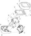
图3为图1空气品质检测装置的分解立体图。FIG. 3 is an exploded perspective view of the air quality detection device of FIG. 1 .
图4为空气品质检测装置移除前壳的立体图。FIG. 4 is a perspective view of the air quality detection device with the front cover removed.
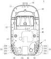
图5为底座的侧视图。Figure 5 is a side view of the base.
图6为图4空气品质检测装置的X-X剖面图。FIG. 6 is an X-X sectional view of the air quality detection device of FIG. 4 .
图7为图6的局部A的放大视图。FIG. 7 is an enlarged view of part A of FIG. 6 .
图8为本发明空气品质检测装置另一实施例的立体示意图。FIG. 8 is a three-dimensional schematic diagram of another embodiment of the air quality detection device of the present invention.
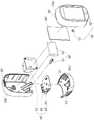
图9为图8空气品质检测装置的分解立体图。FIG. 9 is an exploded perspective view of the air quality detection device of FIG. 8 .
图10为图8空气品质检测装置移除前壳的立体图。FIG. 10 is a perspective view of the air quality detection device of FIG. 8 with the front cover removed.
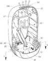
图11为图8空气品质检测装置的Y-Y剖面图。FIG. 11 is a sectional view taken along the line Y-Y of the air quality detection device of FIG. 8 .
【符号说明】【Symbol Description】
1、1’ 空气品质检测装置1. 1’ air quality detection device
10、10’ 壳体10, 10' housing
10a、10a’ 前壳 10b、10b’ 后壳 10c、10c’ 底座10a, 10a’
11、11’ 进风区11, 11’ air inlet area
12、12’ 气流通道12, 12' air flow channel
13、13’ 排风区13, 13' exhaust area
20、20’ 进气口组20, 20’ air inlet group
21、21’ 第一进气口组21, 21’ The first air inlet group
L1 第一层 211、211’ 第一气孔 R1 孔径
L2 第二层 212、212’ 第二气孔 R2 孔径
L3 第三层 213、213’ 第三气孔 R3 孔径L3 The
L4 第四层 214、214’ 第四气孔 R4 孔径
22、22’ 第二进气口组22, 22' Second air inlet group
221、221’ 第一气孔 222、222’ 第二气孔221, 221'
223、223’ 第三气孔 224、224’ 第四气孔223, 223’ The
30、30’ 排气口组30, 30' exhaust port group
40、40’ 空气检测模块40, 40’ Air Detection Module
41、41’ 粉尘检测元件 42 甲醛检测元件41, 41’
43 一氧化碳检测元件 44、44’ VOC检测元件43 Carbon
45’ 温湿度检测元件 46、46’ 电路板45’ temperature and
50、50’ 供电模块50, 50' power supply module
51、51’ USB接口 52’ 电池51, 51’ USB port 52’ battery
60、60’ 显示组件60, 60' display assembly
70、70’ 控制组件70, 70’ Control Assembly
71 触控按键模块 72 人机界面71
71’ 感应触控弹簧 72’ 触控按钮71’
具体实施方式Detailed ways
为能更清楚地说明本发明,兹举较佳实施例并配合图式详细说明如后。请参阅图1至图7,为本发明空气品质检测装置1的一较佳实施例,用以侦测并显示各项空气品质数据。如图3所示,空气品质检测装置1包含一中空的壳体10,以及设置于壳体10内部的空气检测模块40、供电模块50、显示组件60、控制组件70。In order to describe the present invention more clearly, preferred embodiments are given and described in detail with the drawings as follows. Please refer to FIG. 1 to FIG. 7 , which are a preferred embodiment of the air
如图1至图3所示,壳体10可为多个外壳组装而成,在本实施例中,壳体10由上方的前壳10a、后壳10b及下方的底座10c所组装而成,于底座10c上设置有进气口组20,在本实施例中,进气口组20包含有分别设置于底座10c两侧边的第一进气口组21及第二进气口组22,且于前壳10a及后壳10b的顶部分别设置有互相对应的开槽,将前壳10a及后壳10b两者对接之后,该些互相对应的开槽分别形成通孔而组成一完整的排气口组30;组装完成的壳体10内部形成一空间,其内部空间可区分为邻近壳体10底部并位于底座10c内的进风区11,邻近壳体10顶部且位于前壳10a、后壳10b内的排风区13,以及可连通进风区11、排风区13两者的气流通道12;进风区11与进气口组20连通,使外部环境空气可经由进气口组20而进入壳体10内部的进风区11,排风区13与排气口组30连通,使壳体10内部排风区13的空气可经由排气口组30流出壳体10外。As shown in FIG. 1 to FIG. 3 , the
参照图5至图7,以下将说明进气口组20中位于底座10c一侧的第一进气口组21的细部结构。本实施例的第一进气口组21由多个气孔所组成,其中,多个气孔层层排列,位于同层的气孔的孔径一致,且定义距离壳体10顶部最远的一层气孔为第一层L1,定义距离壳体10顶部次远的一层气孔为第二层L2,依此类推在本实施例中还包含有第三层L3及第四层L4,但不以此为限。多个气孔依以下规则排列:愈靠近壳体10顶部的气孔(平均)孔径越小(允许空气通过的气孔面积越小),愈远离壳体10顶部的气孔(平均)孔径越大(允许空气通过的气孔面积越大),即,在本实施例中,分别位于各层L1、L2、L3、L4的各气孔211、212、213、214的水平方向孔径一致,但位于第一层L1的第一气孔211的垂直方向(最大)孔径R1大于位于第二层L2的第二气孔212的垂直方向(最大)孔径R2,位于第二层L2的第二气孔212的垂直方向(最大)孔径R2大于位于第三层L3的第三气孔213的垂直方向(最大)孔径R3,位于第三层L3的第三气孔213的垂直方向(最大)孔径R3大于位于第四层L4的第四气孔214的垂直方向(最大)孔径R4。第二气孔212的垂直方向(最大)孔径R2约为第一气孔211的垂直方向(最大)孔径R1的40%至90%,第三气孔213的垂直方向(最大)孔径R3约为第二气孔212的垂直方向(最大)孔径R2的40%至90%,第四气孔214的垂直方向(最大)孔径R4约为第三气孔213的垂直方向(最大)孔径R3的40%至90%。其中,第一气孔211、第二气孔212及第三气孔213大致呈垂直方向孔径依序逐变小的长椭圆形,而第四气孔214则大致呈垂直方向孔径最小并等于水平方向孔径的圆形,如图5所示,但气孔形状不以此为限。位于底座10c另一侧的第二进气口组22与第一进气口组21对应设置且构造相同,第二进气口组22同样由多个气孔层层排列组成,且同样包含有位于第一层的第一气孔221、位于第二层的第二气孔222、位于第三层的第三气孔223以及位于第四层的第四气孔224等,其孔径变化同于第一进气口组21,此处不再赘述。5 to 7 , the detailed structure of the first
位于壳体10顶部的排气口组30由多个长形通孔所组成,且进气口组20允许空气通过的总面积约为排气口组30允许空气通过的总面积的2至4倍。The
空气检测模块40固设于壳体10内部,且可被同样固设于壳体10内部的供电模块50所驱动,以检测通过空气品质检测模块40的空气成分及状态。在本实施例中,空气检测模块40包含有粉尘检测元件41、甲醛检测元件42、一氧化碳检测元件43、VOC检测元件44以及电路板46;如图4及图6所示,电路板46设置于进风区11并横跨部分的气流通道12,甲醛检测元件42、一氧化碳检测元件43、VOC检测元件44设置于进风区11且邻近进气口组20,而粉尘检测元件41则设置于气流通道12且偏中间位置。供电模块50包含一邻近后壳10b设置的USB接口51,后壳10b对应USB接口51处具有开口,可供USB接口51与外部电源如:市电系统、可携式电源等连接。The
壳体10上还设置有显示组件60,显示组件60与空气品质检测模块40耦接,在本实施例中以一液晶显示模块表示;此显示组件60可以简洁的方式呈现空气品质的状态内容,即时提醒使用者,提供影响人体健康空气品质信息。The
控制组件70与空气品质检测模块40耦接,在本实施例中,控制组件70由触控按键模块71及人机界面72所构成,其中人机界面72以设在前壳10a向内凹陷的按钮表示,但不以此为限,亦可为向外凸出或印刷的按钮,触控按键模块71则位于壳体10内,并与人机界面72的各按钮对应配置,使用者可通过操作人机界面72以触发触控按键模块71,进而控制空气品质检测模块40的开启、关闭、调整显示状态等动作。The
请参阅图6及图7,以下将说明空气品质检测装置1中各结构设计的功效,及其运作时壳体10内部气流的流动状况。使用者透过USB传输线将USB接口51与外部电源连接,并操作控制组件70使空气品质检测模块40开始动作,由于各检测元件在工作时均会发热,使得各检测元件周围的空气被加热,又由于热空气的密度较冷空气小,基于热空气上升原理,加热后的空气向上运动,此时下方空气将上升以填补所遗留空缺,造成空气呈现向上流动的趋势,如此使得壳体10内部开始产生热对流。再者,考量各检测元件在工作时的发热量不同及热对流原理的相互影响,本实施例进一步依照发热量较大的元件较靠上,发热量较小的元件较靠下的设计原理进行各检测元件的配置,例如:粉尘检测元件41工作时的发热量大于其他检测元件,因此在本实施例中将粉尘检测元件41设置于其他检测元件上方,粉尘检测元件41下方则分别设置有其他检测元件,例如:甲醛检测元件42、一氧化碳检测元件43、VOC检测元件44;顺应热对流趋势,此配置可加速壳体10内部气流的对流速度。Please refer to FIG. 6 and FIG. 7 , the following will describe the effects of various structural designs in the air
热空气开始上升后,将沿气流通道12流至排风区13,最终通过排气口组30离开壳体10。与此同时,外部环境空气将从第一及第二进气口组21、22进入壳体10以填补内部空缺;由于第一及第二进气口组21、22各层气孔孔径大小的变化(即允许空气通过的气孔面积变化),导致通过第一气孔211、221的空气的流速将小于通过第二气孔212、222的空气的流速,根据伯努利定律(Bernoulli's Law)可知,气体流速、高低差距、流场压力,三者存在一恒定关系,在高低差距大致不变的状态下,流速低则压力大,流速高则压力小,使得进风区11邻近第一气孔211、221的区域由于空气流速相对较慢而形成一相对高压区,进风区11邻近第二气孔212、222的区域由于空气流速相对较快而形成一相对低压区,两处区域因此形成压力差,驱使通过第一气孔211、221的空气自相对高压区朝向相对低压区流动,进而推动已通过第二气孔212、222且位在相对低压区的空气,而加速位在相对低压区的空气进入气流通道12,如图7所示。可以理解的是,由于孔径的变化趋势,通过第二气孔212、222的空气的流速亦小于通过第三气孔213、223的空气的流速,因此进风区11邻近第二气孔212、222的区域形成相对高压区,进风区11邻近第三气孔213、223的区域则形成相对低压区,两处形成压力差,使得通过第二气孔212、222的空气推动通过第三气孔213、223的空气向上流动,如此循环,通过第三气孔213、223的空气亦将推动通过第四气孔214、224的空气向上流动。气孔的孔径渐变设计使得外部空气进入进气口组20后容易向上方推进,气体自然有向上流动的趋势,且因气流牵引速度加快,整体进气口组20因此能均匀地有效入气。After the hot air starts to rise, it will flow to the
外部环境空气进入壳体10后通过位于进风区11的检测元件,且经前述压差作用因此向上流动,接着通过位于气流通道12的甲醛检测元件42、一氧化碳检测元件43、VOC检测元件44,再通过位于上方的粉尘检测元件41,各检测元件41、42、43、44分别对通过的空气进行检测,并将检测结果显示于显示组件60上,供使用者检视空气品质状态。与此同时,通过空气检测模块40的空气再度被加热,基于热空气上升原理,再次上升并通过排风区13并经由排气口组30离开壳体10,下方的外部环境空气因而经由进气口组20进入壳体10内递补,如此循环,壳体10内部空气对流良好,而无滞留等现象发生。再者,从烟囱效应(StackEffect)原理可知,在进出气口距离高度及内部平均工作温度大致不变的情况下,流速与进出气口组允许空气通过的面积呈正比,且当进气口组允许空气通过面积对出气口组允许空气通过的面积比为2倍时,流速增加约27%,当进气口组允许空气通过的面积对出气口组允许空气通过的面积的比为4倍时,流速增加约37%;在本实施例中,设计将进气口组20允许空气通过的总面积调整为排气口组30允许空气通过的总面积的2至4倍,以提高空气通过壳体10内部的流速,增加壳体10内外对流速度。After the external ambient air enters the
总的来说,基于空气检测模块40自身的发热、各检测元件的排列关系、进气口组20结构的优化以及进气口组20允许空气通过的面积和出气口组30允许空气通过的面积差异的设计,可促进整体空气品质检测装置1壳体10内部的气体流动,及空气检测模块40的检测作用,并减少因装设电扇所造成的噪音及损害风险,进而增加检测装置运作的稳定性。In general, based on the heat generation of the
请参阅图8至图11,为本发明空气品质检测装置1’的另一较佳实施例,其壳体10’、壳体10’上的进气口组20’及排气口组30’、显示组件60’、控制组件70’均与前述实施例大致相同,此实施例目的在于提供另一种空气检测模块40’与供电模块50’的选择。在本实施例中,空气检测模块40’包含有粉尘检测元件41’、VOC检测元件44’及温湿度检测元件45’、电路板46’;如图10及图11所示,电路板46’设置于进风区11’内且邻近底座10c’的底部,VOC检测元件44’及温湿度检测元件45’设置于进风区11’内且邻近进气口组20’,而粉尘检测元件41’则设置于气流通道12’且偏中上位置。供电模块50’则包含有邻近后壳10b’设置的USB接口51’,后壳10b’对应USB接口51’处具有开口,可供USB接口51’与外部电源连接,差异在于,本实施例的供电模块50’还包含有内置于机壳10内且邻近前壳10a’设置的电池52’,电池52’可为一锂电池等的可充电电池,以做为空气品质检测装置1’的电源。此外,控制组件70’包含感应触控弹簧71’及触控按钮72’,其中,感应触控弹簧71’设于壳体10’内与空气检测模块40’耦接,触控按钮72’则设于前壳10a’供使用者操作,以触发感应触控弹簧71’驱动空气检测模块40’动作。Please refer to FIG. 8 to FIG. 11 , which is another preferred embodiment of the air
值得说明的是,此实施例同样依照发热量较大的元件较靠上的设计原理,将粉尘检测元件41’设置于VOC检测元件44’及温湿度检测元件45’上方,可加速热对流趋势。且由于温湿度检测元件45’设置于邻近进气口组20’的区域,使得由进气口组20’进入的空气可即时为温湿度检测元件45’所检测,确保温湿度数据尚未受加热而失真,以上配置符合各检测元件的作用需求,使整体空气品质检测装置1’响应速度快且准确。再者,以电池52’作为装置电源,可令空气品质检测装置1’具有可携性,且透过USB接口51’与外部电源连接时亦可对电池52’充电,以延长携出时的运作时间。It is worth noting that, in this embodiment, the
请参阅图11,以下将说明当空气品质检测装置1’动作时,壳体10’内部气流的流动状况。使用者操作控制组件70’使空气品质检测模块40’开始动作,空气品质检测模块40’的各检测元件41’、44’、45’运作并逐渐产生热能,热能使得位于各检测元件41’、44’、45’周围的空气加热,由于热空气上升原理,热空气上升离开各检测元件41’、44’、45’周围区域,下方的气体则向上填补所遗留空缺,因此造成一向上气流,使得热空气最终从排气区13’由排气口组30’离开壳体10’,同时外部环境空气将从第一进气口组21’及第二进气口组22’进入壳体10’的进气区11’,空气在经过各层气孔211’、212’、213’、214’、221’、222’、223’、224’后,与前述实施例相同地,因为各层气孔间孔径(即允许空气通过的气孔面积)的差异,位于不同层的空气间产生速度差进而产生压力差,由于较下层空气压力相对较大,较上层空气压力相对较小,因此下层空气推动上层空气向上朝向气流通道12’方向移动,与此同时,空气通过空气品质检测模块40’的各检测元件41’、44’、45’而受到检测,空气品质检测模块40’的检测结果则显示于显示组件60’上,供使用者检视空气品质状态。通过空气品质检测模块40’的空气将再度被加热,热空气将上升而下方的气体则向上填补,因此再次造成一向上的气流,而下方环境空气将经由进气口组20’进入壳体10’内,如此循环,使得壳体10’内部的空气流动良好。Please refer to FIG. 11 , the following will describe the flow condition of the air flow inside the housing 10' when the air quality detection device 1' operates. The user operates the control assembly 70' to start the air quality detection module 40', and each
在较佳实施例的详细说明中所提出的具体实施例仅用以方便说明本发明的技术内容,而非将本发明狭义地限制于上述实施例,在不超出本发明的精神及以下申请专利范围的情况,所做的种种变化实施,皆属于本发明的范围。The specific embodiments proposed in the detailed description of the preferred embodiments are only used to facilitate the description of the technical content of the present invention, rather than limiting the present invention to the above-mentioned embodiments in a narrow sense. In the case of the scope, various changes and implementations made belong to the scope of the present invention.
Claims (12)
Priority Applications (1)
| Application Number | Priority Date | Filing Date | Title |
|---|---|---|---|
| CN201910349445.3ACN111855893B (en) | 2019-04-28 | 2019-04-28 | Air quality detection device |
Applications Claiming Priority (1)
| Application Number | Priority Date | Filing Date | Title |
|---|---|---|---|
| CN201910349445.3ACN111855893B (en) | 2019-04-28 | 2019-04-28 | Air quality detection device |
Publications (2)
| Publication Number | Publication Date |
|---|---|
| CN111855893A CN111855893A (en) | 2020-10-30 |
| CN111855893Btrue CN111855893B (en) | 2022-08-26 |
Family
ID=72966122
Family Applications (1)
| Application Number | Title | Priority Date | Filing Date |
|---|---|---|---|
| CN201910349445.3AActiveCN111855893B (en) | 2019-04-28 | 2019-04-28 | Air quality detection device |
Country Status (1)
| Country | Link |
|---|---|
| CN (1) | CN111855893B (en) |
Citations (13)
| Publication number | Priority date | Publication date | Assignee | Title |
|---|---|---|---|---|
| CN1129436A (en)* | 1993-06-24 | 1996-08-21 | 辛普里马蒂克工程公司 | Speed-controllable air conveyor without baffles |
| CN1133018A (en)* | 1993-09-03 | 1996-10-09 | 高耶恩控制有限公司 | Bag house cleaning systems |
| CN2695174Y (en)* | 2004-04-29 | 2005-04-27 | 普慧企业股份有限公司 | Aerial fog cooling device of processing machine |
| CN201000159Y (en)* | 2006-12-21 | 2008-01-02 | 日扬科技股份有限公司 | Unpowered exhaust device |
| TWM391626U (en)* | 2010-06-15 | 2010-11-01 | Gem Sun Technologies Co Ltd | LED lamp having air flow guiding function |
| CN202914209U (en)* | 2012-08-10 | 2013-05-01 | 河南创世电机科技有限公司 | Air filter used for 188F gasoline engine |
| CN104697821A (en)* | 2013-12-09 | 2015-06-10 | 深圳市鑫汇科股份有限公司 | Air detection device, air sampling device and air sampling method |
| CN105259087A (en)* | 2015-11-16 | 2016-01-20 | 武汉百络优物联科技有限公司 | Air detection device and method |
| CN205174562U (en)* | 2015-11-30 | 2016-04-20 | 北京无量威德科技发展有限公司 | Air purifying device |
| CN105823515A (en)* | 2016-05-06 | 2016-08-03 | 中科同德(北京)生态科技有限公司 | Indoor air environment monitoring equipment |
| CN107261656A (en)* | 2014-04-14 | 2017-10-20 | 罗瑞真 | Air purifying device |
| CN206831752U (en)* | 2017-06-28 | 2018-01-02 | 福建师范大学 | One kind energy-conservation cooling ventilation unit |
| CN109301786A (en)* | 2018-10-31 | 2019-02-01 | 国家电网有限公司 | A cable trench cover plate capable of automatic dehumidification |
- 2019
- 2019-04-28CNCN201910349445.3Apatent/CN111855893B/enactiveActive
Patent Citations (13)
| Publication number | Priority date | Publication date | Assignee | Title |
|---|---|---|---|---|
| CN1129436A (en)* | 1993-06-24 | 1996-08-21 | 辛普里马蒂克工程公司 | Speed-controllable air conveyor without baffles |
| CN1133018A (en)* | 1993-09-03 | 1996-10-09 | 高耶恩控制有限公司 | Bag house cleaning systems |
| CN2695174Y (en)* | 2004-04-29 | 2005-04-27 | 普慧企业股份有限公司 | Aerial fog cooling device of processing machine |
| CN201000159Y (en)* | 2006-12-21 | 2008-01-02 | 日扬科技股份有限公司 | Unpowered exhaust device |
| TWM391626U (en)* | 2010-06-15 | 2010-11-01 | Gem Sun Technologies Co Ltd | LED lamp having air flow guiding function |
| CN202914209U (en)* | 2012-08-10 | 2013-05-01 | 河南创世电机科技有限公司 | Air filter used for 188F gasoline engine |
| CN104697821A (en)* | 2013-12-09 | 2015-06-10 | 深圳市鑫汇科股份有限公司 | Air detection device, air sampling device and air sampling method |
| CN107261656A (en)* | 2014-04-14 | 2017-10-20 | 罗瑞真 | Air purifying device |
| CN105259087A (en)* | 2015-11-16 | 2016-01-20 | 武汉百络优物联科技有限公司 | Air detection device and method |
| CN205174562U (en)* | 2015-11-30 | 2016-04-20 | 北京无量威德科技发展有限公司 | Air purifying device |
| CN105823515A (en)* | 2016-05-06 | 2016-08-03 | 中科同德(北京)生态科技有限公司 | Indoor air environment monitoring equipment |
| CN206831752U (en)* | 2017-06-28 | 2018-01-02 | 福建师范大学 | One kind energy-conservation cooling ventilation unit |
| CN109301786A (en)* | 2018-10-31 | 2019-02-01 | 国家电网有限公司 | A cable trench cover plate capable of automatic dehumidification |
Also Published As
| Publication number | Publication date |
|---|---|
| CN111855893A (en) | 2020-10-30 |
Similar Documents
| Publication | Publication Date | Title |
|---|---|---|
| CN204116178U (en) | Air detection instrument | |
| CN217116774U (en) | Server cabinet and data center | |
| CN111855893B (en) | Air quality detection device | |
| CN103592058B (en) | The monitoring device of electric appliance refrigerated amount and air-conditioning | |
| CN209135577U (en) | Ion blower | |
| TW202040128A (en) | Air quality testing device | |
| CN102252955A (en) | Constant temperature and constant humidity cabinet | |
| CN102892265A (en) | Power electronic equipment, cabinet body thereof and cabinet door of cabinet body | |
| CN104266283B (en) | Table top air conditioner | |
| CN201749535U (en) | Detection system of smoke type fire alarm | |
| CN113040435B (en) | An aerosol generating device | |
| CN108758825A (en) | Wall-hanging air conditioner indoor unit | |
| CN210399141U (en) | Indoor unit of air conditioner | |
| CN208651295U (en) | A bladeless fan with display function | |
| CN214962655U (en) | An aerosol generating device | |
| CN204987345U (en) | Humidifier and inferior valve subassembly thereof | |
| CN204787005U (en) | Humidifier | |
| CN104279638B (en) | Desktop air conditioner | |
| CN116697453A (en) | An air conditioner indoor unit | |
| CN116008485A (en) | Gas collection device and method | |
| CN215175846U (en) | Intelligent controller of fresh air system | |
| CN221865217U (en) | Cooling dining chair | |
| CN222284693U (en) | Electronic atomization device | |
| CN219763158U (en) | Electric oven with control panel heat dissipation device | |
| CN210463283U (en) | Humidifying device and air conditioner |
Legal Events
| Date | Code | Title | Description |
|---|---|---|---|
| PB01 | Publication | ||
| PB01 | Publication | ||
| SE01 | Entry into force of request for substantive examination | ||
| SE01 | Entry into force of request for substantive examination | ||
| GR01 | Patent grant | ||
| GR01 | Patent grant |