CN111852256A - An adjustable door frame assembly and installation method and shower door installation structure - Google Patents
An adjustable door frame assembly and installation method and shower door installation structureDownload PDFInfo
- Publication number
- CN111852256A CN111852256ACN202010736286.5ACN202010736286ACN111852256ACN 111852256 ACN111852256 ACN 111852256ACN 202010736286 ACN202010736286 ACN 202010736286ACN 111852256 ACN111852256 ACN 111852256A
- Authority
- CN
- China
- Prior art keywords
- door frame
- fixed
- installation
- frame assembly
- sliding end
- Prior art date
- Legal status (The legal status is an assumption and is not a legal conclusion. Google has not performed a legal analysis and makes no representation as to the accuracy of the status listed.)
- Pending
Links
- 238000009434installationMethods0.000titleclaimsabstractdescription82
- 238000000034methodMethods0.000titleclaimsabstractdescription13
- 230000007246mechanismEffects0.000claimsdescription9
- 230000000903blocking effectEffects0.000claimsdescription7
- 230000002265preventionEffects0.000claimsdescription3
- 238000005553drillingMethods0.000abstractdescription7
- 229910052782aluminiumInorganic materials0.000description37
- XAGFODPZIPBFFR-UHFFFAOYSA-NaluminiumChemical compound[Al]XAGFODPZIPBFFR-UHFFFAOYSA-N0.000description37
- 239000000463materialSubstances0.000description37
- 238000010586diagramMethods0.000description12
- 238000013461designMethods0.000description11
- 230000008569processEffects0.000description4
- 239000011521glassSubstances0.000description3
- 238000010079rubber tappingMethods0.000description3
- 239000000853adhesiveSubstances0.000description2
- 230000001070adhesive effectEffects0.000description2
- 238000003780insertionMethods0.000description2
- 230000037431insertionEffects0.000description2
- 230000007774longtermEffects0.000description2
- 230000007704transitionEffects0.000description2
- XLYOFNOQVPJJNP-UHFFFAOYSA-NwaterSubstancesOXLYOFNOQVPJJNP-UHFFFAOYSA-N0.000description2
- 230000009471actionEffects0.000description1
- 238000013459approachMethods0.000description1
- 230000008602contractionEffects0.000description1
- 239000003292glueSubstances0.000description1
- 238000011900installation processMethods0.000description1
- 239000000696magnetic materialSubstances0.000description1
- 229910052751metalInorganic materials0.000description1
- 239000002184metalSubstances0.000description1
- 239000007769metal materialSubstances0.000description1
- 238000012986modificationMethods0.000description1
- 230000004048modificationEffects0.000description1
- 230000003068static effectEffects0.000description1
Images


Classifications
- E—FIXED CONSTRUCTIONS
- E06—DOORS, WINDOWS, SHUTTERS, OR ROLLER BLINDS IN GENERAL; LADDERS
- E06B—FIXED OR MOVABLE CLOSURES FOR OPENINGS IN BUILDINGS, VEHICLES, FENCES OR LIKE ENCLOSURES IN GENERAL, e.g. DOORS, WINDOWS, BLINDS, GATES
- E06B1/00—Border constructions of openings in walls, floors, or ceilings; Frames to be rigidly mounted in such openings
- E06B1/04—Frames for doors, windows, or the like to be fixed in openings
- E06B1/52—Frames specially adapted for doors
- E—FIXED CONSTRUCTIONS
- E05—LOCKS; KEYS; WINDOW OR DOOR FITTINGS; SAFES
- E05D—HINGES OR SUSPENSION DEVICES FOR DOORS, WINDOWS OR WINGS
- E05D11/00—Additional features or accessories of hinges
- E—FIXED CONSTRUCTIONS
- E05—LOCKS; KEYS; WINDOW OR DOOR FITTINGS; SAFES
- E05D—HINGES OR SUSPENSION DEVICES FOR DOORS, WINDOWS OR WINGS
- E05D7/00—Hinges or pivots of special construction
- E05D7/04—Hinges adjustable relative to the wing or the frame
- E—FIXED CONSTRUCTIONS
- E05—LOCKS; KEYS; WINDOW OR DOOR FITTINGS; SAFES
- E05D—HINGES OR SUSPENSION DEVICES FOR DOORS, WINDOWS OR WINGS
- E05D7/00—Hinges or pivots of special construction
- E05D7/08—Hinges or pivots of special construction for use in suspensions comprising two spigots placed at opposite edges of the wing, especially at the top and the bottom, e.g. trunnions
- E05D7/081—Hinges or pivots of special construction for use in suspensions comprising two spigots placed at opposite edges of the wing, especially at the top and the bottom, e.g. trunnions the pivot axis of the wing being situated near one edge of the wing, especially at the top and bottom, e.g. trunnions
- E—FIXED CONSTRUCTIONS
- E06—DOORS, WINDOWS, SHUTTERS, OR ROLLER BLINDS IN GENERAL; LADDERS
- E06B—FIXED OR MOVABLE CLOSURES FOR OPENINGS IN BUILDINGS, VEHICLES, FENCES OR LIKE ENCLOSURES IN GENERAL, e.g. DOORS, WINDOWS, BLINDS, GATES
- E06B3/00—Window sashes, door leaves, or like elements for closing wall or like openings; Layout of fixed or moving closures, e.g. windows in wall or like openings; Features of rigidly-mounted outer frames relating to the mounting of wing frames
- E06B3/70—Door leaves
- E06B3/72—Door leaves consisting of frame and panels, e.g. of raised panel type
Landscapes
- Engineering & Computer Science (AREA)
- Mechanical Engineering (AREA)
- Civil Engineering (AREA)
- Structural Engineering (AREA)
- Residential Or Office Buildings (AREA)
- Wing Frames And Configurations (AREA)
Abstract
Translated fromChinese
Description
Translated fromChinese技术领域technical field
本发明涉及但不限于卫浴领域,更具体地,涉及一种可调的门框组件和安装方法及淋浴门安装结构。The present invention relates to, but is not limited to, the field of sanitary ware, and more particularly, to an adjustable door frame assembly, an installation method and a shower door installation structure.
背景技术Background technique
淋浴门通常靠着墙壁安装,淋浴门与墙壁之间通过至少两组连接组件进行安装连接,并且要保持淋浴门在安装后处于竖直状态。然而,由于淋浴房的墙面通常非完全竖直,如果完全沿着墙面安装,可能出现淋浴门在安装后不处于竖直状态的现象,影响淋浴门的开合。为了解决这一问题,安装时需要调节淋浴门的上、下端与墙面之间的距离以保证淋浴门处于竖直状态。The shower door is usually installed against the wall, and the shower door and the wall are installed and connected through at least two sets of connecting components, and the shower door should be kept in a vertical state after installation. However, since the wall of the shower room is usually not completely vertical, if it is installed completely along the wall, the shower door may not be in a vertical state after installation, which affects the opening and closing of the shower door. In order to solve this problem, it is necessary to adjust the distance between the upper and lower ends of the shower door and the wall during installation to ensure that the shower door is in a vertical state.
为实现调节,淋浴门通常包括用于与墙面固定的固定门框,以及与门板连接的移动门框,固定门框与移动门框通过至少两组连接组件进行连接。安装时,将固定门框靠着墙壁固定,然后将移动门框安装至固定门框上,安装过程中通过调节连接组件的伸缩来将移动门框调节至竖直状态,最后在移动门框和固定门框上钻孔并用螺钉等将移动门框和固定门框紧固在一起。然而,一方面,钻孔需要至少两人配合才能完成,并且需要耗费较长时间,在整个钻孔过程中需要人力将移动门框与固定门框保持为相对静止,安装难度较大,且安装后不能进行二次调节。另一方面,由于人力操作具有较大的不稳定性,例如在钻孔过程中移动门框相对固定门框移动,不仅影响淋浴门的外观,而且可能造成固定门框和移动门框损坏,甚至可能造成淋浴门报废。In order to realize adjustment, the shower door usually includes a fixed door frame for fixing to the wall surface, and a moving door frame connected with the door panel. The fixed door frame and the moving door frame are connected by at least two sets of connecting components. During installation, fix the fixed door frame against the wall, and then install the mobile door frame on the fixed door frame. During the installation process, adjust the expansion and contraction of the connecting component to adjust the mobile door frame to a vertical state, and finally drill holes on the mobile door frame and the fixed door frame. And fasten the moving door frame and the fixed door frame together with screws, etc. However, on the one hand, drilling requires at least two people to complete the drilling, and it takes a long time. During the whole drilling process, manpower is required to keep the moving door frame and the fixed door frame relatively static, which is difficult to install and cannot be installed after installation. Make a second adjustment. On the other hand, due to the large instability of manual operation, for example, the moving door frame moves relative to the fixed door frame during the drilling process, which not only affects the appearance of the shower door, but also may cause damage to the fixed door frame and the moving door frame, and may even cause the shower door to be scrapped .
发明内容SUMMARY OF THE INVENTION
本公开实施例提供了一种可调的门框组件,包括固定在墙壁上的固定门框,以及用以安装门板的移动门框,所述移动门框的顶部和底部设有转轴座,包括调节件和紧固件,任一所述转轴座设有导向槽,所述调节件包括固定端和滑动端,所述固定端与所述固定门框连接,所述滑动端设置为沿所述导向槽滑动,通过使所述移动门框靠近或远离所述固定门框调节所述移动门框的竖直状态;所述紧固件设置在所述滑动端,使所述滑动端固定在所述导向槽内一处。An embodiment of the present disclosure provides an adjustable door frame assembly, including a fixed door frame fixed on a wall, and a moving door frame for installing a door panel, the top and bottom of the moving door frame are provided with pivot seats, including an adjustment member and a tightening member. Any one of the rotating shaft seats is provided with a guide groove, the adjusting member includes a fixed end and a sliding end, the fixed end is connected with the fixed door frame, and the sliding end is set to slide along the guide groove, and the sliding end is configured to slide along the guide groove. The vertical state of the moving door frame is adjusted by making the moving door frame close to or away from the fixed door frame; the fastener is arranged on the sliding end, so that the sliding end is fixed at one place in the guide groove.
一种可能的设计,所述转轴座设有防脱机构,所述防脱机构是一处于所述滑动端的滑动路径上的支撑杆,所述支撑杆设置在所述转轴座靠近所述固定门框的一端,用以在所述紧固件失效情况下避免所述滑动端脱离所述导向槽而导致移动门框掉落。A possible design, the pivot seat is provided with an anti-drop mechanism, the anti-drop mechanism is a support rod located on the sliding path of the sliding end, and the support rod is arranged on the pivot seat close to the fixed door frame. One end of the sliding end is used to prevent the sliding end from escaping from the guide groove and causing the moving door frame to fall when the fastener fails.
一种可能的设计,所述转轴座设置有容纳所述调节件的安装槽,所述安装槽的延伸方向垂直于所述移动门框,所述安装槽的槽壁设置有所述导向槽。In a possible design, the rotating shaft seat is provided with an installation groove for accommodating the adjusting member, the extension direction of the installation groove is perpendicular to the moving door frame, and the guide groove is provided on the groove wall of the installation groove.
一种可能的设计,所述滑动端设置有向两侧突出的凸台,所述凸台插入所述导向槽内。In a possible design, the sliding end is provided with bosses protruding to both sides, and the bosses are inserted into the guide grooves.
一种可能的设计,所述支撑杆设置在所述安装槽靠近所述固定门框的一端,所述支撑杆的两端与所述安装槽的槽壁相连,所述滑动端设有挡筋,当所述滑动端移至所述安装槽靠近所述固定门框的一端时,所述挡筋与所述支撑杆相抵,用以限制所述凸台脱离所述导向槽。In a possible design, the support rod is arranged at one end of the installation groove close to the fixed door frame, the two ends of the support rod are connected to the groove wall of the installation groove, and the sliding end is provided with a retaining rib, When the sliding end moves to an end of the installation slot close to the fixed door frame, the retaining rib abuts against the support rod, so as to restrict the boss from leaving the guide slot.
一种可能的设计,所述转轴座在所述安装槽远离所述固定门框一端设有安装缺口,用以将所述凸台滑入所述导向槽。In a possible design, an installation notch is provided at the end of the installation groove away from the fixed door frame of the rotating shaft seat, so as to slide the boss into the guide groove.
一种可能的设计,所述凸台设置在所述挡筋上,所述挡筋向下延伸且向所述固定门框一侧倾斜。In a possible design, the boss is arranged on the retaining rib, and the retaining rib extends downward and is inclined to the side of the fixed door frame.
一种可能的设计,所述安装槽的槽底对应所述支撑杆设置有避让缺口。In a possible design, the bottom of the installation groove is provided with an avoidance notch corresponding to the support rod.
一种可能的设计,所述紧固件是一顶丝,所述滑动端设有上下贯通的螺纹孔,所述顶丝贯穿所述螺纹孔且抵在所述安装槽的槽底。In a possible design, the fastener is a top wire, the sliding end is provided with a threaded hole that penetrates up and down, and the top wire penetrates the threaded hole and abuts against the bottom of the installation groove.
一种可能的设计,所述固定端设有勾状的钩头,所述钩头夹在墙壁与所述固定门框之间。In a possible design, the fixed end is provided with a hook-shaped hook head, and the hook head is clamped between the wall and the fixed door frame.
一种可能的设计,所述钩头在面向墙壁的端面上设有弧面,所述弧面延伸至所述钩头的钩尖处。In a possible design, the hook head is provided with an arc surface on the end face facing the wall, and the arc surface extends to the hook tip of the hook head.
一种可能的设计,所述固定门框对应调节件设有定位缺口,所述钩头扣在所述定位缺口处。In a possible design, a positioning notch is provided on the corresponding adjusting member of the fixed door frame, and the hook head is fastened at the positioning notch.
本发明实施例提供了一种安装方法,应用于上述的可调的门框组件,包括:An embodiment of the present invention provides an installation method, which is applied to the above-mentioned adjustable door frame assembly, including:
安装所述固定门框,组装带有所述转轴座的所述移动门框;installing the fixed door frame, and assembling the moving door frame with the pivot seat;
将所述固定门框和移动门框对应插接;Correspondingly inserting the fixed door frame and the moving door frame;
保持所述调节件竖直并将所述滑动端塞入所述安装缺口,使所述凸台滑入所述导向槽;Keep the adjustment piece upright and insert the sliding end into the installation notch, so that the boss slides into the guide groove;
以凸台的轴线为中心旋转所述调节件,使所述固定端旋向所述固定门框并与所述固定门框扣合;Rotate the adjusting member with the axis of the boss as the center, so that the fixed end is rotated toward the fixed door frame and fastened with the fixed door frame;
调节所述移动门框,以使所述移动门框竖直;adjusting the moving door frame so that the moving door frame is vertical;
拧紧所述紧固件,将所述滑动端顶紧在所述转轴座。Tighten the fastener to press the sliding end against the shaft seat.
本公开实施例提供了一种淋浴门安装结构,包括门板和上述的可调的门框组件,所述固定门框与墙壁固定,所述移动门框连接有门板,处于所述移动门框顶部的转轴座设有所述调节件和紧固件,所述移动门框的底部与地面粘接固定。An embodiment of the present disclosure provides a shower door installation structure, including a door panel and the above-mentioned adjustable door frame assembly, the fixed door frame is fixed to a wall, the movable door frame is connected with a door panel, and a rotating shaft seat at the top of the movable door frame is provided There are the adjusting pieces and fasteners, and the bottom of the moving door frame is bonded and fixed with the ground.
本公开实施例的门框组件在调节竖直状态时,无需钻孔,节省了人力和时间,而且不会损坏边框表面而影响产品的外观。When adjusting the vertical state of the door frame assembly of the embodiment of the present disclosure, no drilling is required, which saves manpower and time, and does not damage the surface of the frame to affect the appearance of the product.
本发明实施例的门框组件设有防脱机构,可在所述紧固件失效情况下避免滑动端脱离导向槽而导致移动门框掉落,既利于安装,又可防止长期使用后紧固件松动而导致门板掉落,大大提升了使用体验。The door frame assembly of the embodiment of the present invention is provided with an anti-dropping mechanism, which can prevent the sliding end from breaking away from the guide groove and cause the moving door frame to fall when the fastener fails, which is not only convenient for installation, but also prevents the fastener from loosening after long-term use. As a result, the door panel fell, which greatly improved the user experience.
本发明的其它特征和优点将在随后的说明书中阐述,并且,部分地从说明书中变得显而易见,或者通过实施本发明而了解。本发明的目的和其他优点可通过在说明书以及附图中所特别指出的结构来实现和获得。Other features and advantages of the present invention will be set forth in the description which follows, and in part will be apparent from the description, or may be learned by practice of the invention. The objectives and other advantages of the invention may be realized and attained by the structure particularly pointed out in the description and drawings.
附图说明Description of drawings
附图用来提供对本发明技术方案的进一步理解,并且构成说明书的一部分,与本申请的实施例一起用于解释本发明的技术方案,并不构成对本发明技术方案的限制。The accompanying drawings are used to provide a further understanding of the technical solutions of the present invention, and constitute a part of the specification. They are used to explain the technical solutions of the present invention together with the embodiments of the present application, and do not limit the technical solutions of the present invention.
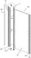
图1为根据本发明的一实施例的淋浴门安装结构第一示意图;1 is a first schematic diagram of a shower door installation structure according to an embodiment of the present invention;
图2为图1中的淋浴门安装结构拆分示意图;Fig. 2 is a schematic diagram of the disassembly of the installation structure of the shower door in Fig. 1;
图3为图1的A处局部放大示意图;Fig. 3 is a partial enlarged schematic diagram at A of Fig. 1;
图4为图1的B处局部放大示意图;Fig. 4 is the partial enlarged schematic diagram at B of Fig. 1;
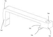
图5为图2的C处局部放大示意图;Fig. 5 is the partial enlarged schematic diagram at C of Fig. 2;
图6为图2的D处局部放大示意图;Fig. 6 is the partial enlarged schematic diagram at D of Fig. 2;
图7为图1中的淋浴门安装结构第二示意图;Fig. 7 is the second schematic diagram of the installation structure of the shower door in Fig. 1;
图8为图5中的调节件示意图;Fig. 8 is the schematic diagram of the adjusting member in Fig. 5;
图9为图5中的上转轴座第一示意图;Fig. 9 is the first schematic diagram of the upper shaft seat in Fig. 5;
图10为图5中的上转轴座第二示意图;Fig. 10 is the second schematic diagram of the upper shaft seat in Fig. 5;
图11为图5中的固定门框示意图;Figure 11 is a schematic diagram of the fixed door frame in Figure 5;
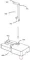
图12为图3中的调节件与转轴座插接示意图;Fig. 12 is a schematic diagram of the plug connection between the adjusting member and the rotating shaft seat in Fig. 3;
图13为图1中的淋浴门安装结构第一剖视图;Fig. 13 is the first sectional view of the installation structure of the shower door in Fig. 1;
图14为图1中的淋浴门安装结构第二剖视图;Figure 14 is a second cross-sectional view of the shower door installation structure in Figure 1;
图15为图1中的淋浴门安装结构第三剖视图;Fig. 15 is the third sectional view of the shower door installation structure in Fig. 1;
图16为图1中的淋浴门安装结构第四剖视图;Figure 16 is a fourth cross-sectional view of the shower door installation structure in Figure 1;
图17为图1中的淋浴门安装结构第五剖视图。FIG. 17 is a fifth cross-sectional view of the shower door installation structure in FIG. 1 .
附图标记:100-固定门框、101-定位缺口、200-移动门框、201-固定铝材、202-转轴铝材、203-防水胶条、204-升降座、205-装饰盖、206-自攻钉、300-门板、301-玻璃板、302-磁吸铝材、303-磁条、400-上转轴座、401-主体、402-转轴、403-安装槽、404-导向槽、405-支撑杆、406-安装缺口、407-避让缺口、408-第一斜面、409-固定孔、410-过渡板、411-固定部、412-转轴部、500-下转轴座、600-顶丝、700-调节杆、701-固定端、702-滑动端、703-钩头、704-螺纹孔、705-挡筋、706-凸台、707-弧面、800-墙壁、801-安装间隙。Reference signs: 100-fixed door frame, 101-positioning notch, 200-movable door frame, 201-fixed aluminum material, 202-rotating shaft aluminum material, 203-waterproof rubber strip, 204-lifting seat, 205-decorative cover, 206-self Tapping screw, 300-door panel, 301-glass panel, 302-magnetic aluminum material, 303-magnetic strip, 400-upper hinge seat, 401-main body, 402-rotating shaft, 403-installation slot, 404-guide slot, 405- Support rod, 406-installation gap, 407-avoidance gap, 408-first slope, 409-fixing hole, 410-transition plate, 411-fixed part, 412-rotating shaft part, 500-lower shaft seat, 600-top wire, 700-Adjusting rod, 701-Fixed end, 702-Sliding end, 703-Hook head, 704-Threaded hole, 705-Retaining rib, 706-Boss, 707-Arc surface, 800-Wall, 801-Installation clearance.
具体实施方式Detailed ways
为使本发明的目的、技术方案和优点更加清楚明白,下文中将结合附图对本发明的实施例进行详细说明。需要说明的是,在不冲突的情况下,本申请中的实施例及实施例中的特征可以相互任意组合。In order to make the objectives, technical solutions and advantages of the present invention clearer, the embodiments of the present invention will be described in detail below with reference to the accompanying drawings. It should be noted that, the embodiments in the present application and the features in the embodiments may be arbitrarily combined with each other if there is no conflict.
请参阅图1至图17的本公开实施例的淋浴门安装结构,该淋浴门安装结构包括门板300和可调的门框组件,该门框组件包括固定在墙壁800上的固定门框100,以及用以安装门板300的移动门框200,固定门框100与移动门框200插接且插接深度可调,以将门板300和移动门框200调整为竖直状态(即垂直于地面)。Please refer to FIG. 1 to FIG. 17 of the shower door installation structure of the embodiment of the present disclosure, the shower door installation structure includes a
如图1至图7所示,该门框组件包括插接的固定门框100和移动门框200,其中,该移动门框200的顶部和底部设有转轴座,两个转轴座因上下位置不同可分为处于顶部的上转轴座400和处于底部的下转轴座500。另外,上转轴座400上设有分体的调节件700和紧固件,该上转轴座400上还设有导向槽404。该调节件700为长条型材,调节件700包括固定端701和滑动端702,该固定端701与固定门框100连接,而滑动端702设置为沿导向槽404滑动,通过使移动门框200靠近或远离固定门框100调节移动门框200的竖直状态。在一些示例性实施例中,该紧固件采用顶丝600,顶丝600设置在滑动端702,使滑动端702固定在导向槽404内一处,锁定移动门框200。As shown in FIG. 1 to FIG. 7 , the door frame assembly includes a fixed
就固定门框100而言,如图2、图7和图11所示,该固定门框100为截面呈半包围的长条铝材,该固定门框100的开口背向墙壁800,即面向移动门框200,而且在固定门框100固定在墙壁800上后,该固定门框100的腹板与墙壁800的墙面之间形成安装间隙801。As for the fixed
就移动门框200而言,如图1至图7及图10所示,该移动门框200除了包括上述上转轴座400和下转轴座500,还包括固定铝材201、转轴铝材202、防水胶条203、升降座204和装饰盖205。其中,固定铝材201为截面呈半包围的长条铝材,该固定铝材201的开口面向墙壁800且宽度略大于固定门框100,使得固定门框100可由固定铝材201的开口插入固定铝材201内,固定门框100插入固定铝材201的深度即为固定门框100与移动门框200的插接深度。转轴铝材202为截面呈全包围的长条铝材,该转轴铝材202与固定铝材201平行且通过上转轴座400和下转轴座500连接。该转轴铝材202的上下两端分别插接有升降座204,该升降座204设有突出的轴座,该升降座204被装饰盖205遮盖且留有插入轴座的通孔。上转轴座400连接转轴铝材202与固定铝材201的方式,与下转轴座500连接转轴铝材202与固定铝材201的方式相同,以上转轴座400为例,该上转轴座400的一部分扣在固定铝材201的上端且通过自攻钉206固定,上转轴座400的另一部分扣在转轴铝材202的上端且设有向下延伸的转轴402,该转轴402可插入升降座204的轴座内,形成上转轴座400与转轴铝材202的旋转连接,即转轴铝材202可绕转轴402的轴线转动,从而可形成门板的开合。另外,该固定铝材201和转轴铝材202之间设有上述防水胶条203,具有弹性的防水胶条203填充固定铝材201和转轴铝材202之间的间隙,在转轴铝材202转动时也可保证密封,防止水由间隙溅出,可提升用户体验。As for the moving
就门板300而言,如图2所示,该门板300包括玻璃板301、磁吸铝材302和磁条303,该玻璃板301的一端可与转轴铝材202固定,另一端固定有磁吸铝材302,该磁条303嵌在磁吸铝材302上,相对应地,门板300另一侧墙壁上可对应上述磁条303设有磁性不同的磁性材料或可被磁铁吸引的金属材料,以锁定合门状态。另外,该门板300的下侧与地面之间留有间隙,方便门板300开合,而该间隙处可对应设有挡水条。As far as the
就调节件700而言,如图8和图12所示,该调节件700为长条金属型材,固定端701和滑动端702分别为调节件700长度方向的两端。该固定端791设有勾状的钩头703,该钩头703向一侧弯折,该滑动端702下端面向安装槽403的槽底延伸出一挡筋705,该挡筋705在自由一端的两侧设有突出且呈圆形的凸台706,该滑动端702还设有贯通的螺纹孔704。另外,钩头703在背向滑动端702的端面上设有弧面707,该弧面707一直有延伸至钩头703的钩尖处。As for the adjusting
上述上转轴座400和下转轴座500的区别在于,上转轴座400上还设有调节件700、顶丝600和导向槽404等。如图9和图10,该上转轴座400包括主体401,该主体401被分为与固定铝材201对应的固定部411,和与转轴铝材202对应的转轴部412,该固定部411设有两个贯通的固定孔409,以自攻钉206贯穿打入到固定铝材201,该转轴部412的下端设有突出的转轴402。该固定部411的顶部设有容纳上述调节件700的安装槽403,该安装槽403沿上转轴座的长度方向布置,一直延伸至转轴部412。该安装槽403的两侧壁在靠近槽底处都设有上述导向槽404,导向槽404与安装槽403同向设置,使得上述调节件700的两个凸台706分别插入两导向槽404内后,该调节件700可在安装槽403内滑动,且仅能沿导向槽404滑动。在固定部411和转轴部412之间设有安装缺口406,安装缺口406处于安装槽403的一端,以使滑动端702的凸台706能滑入到导向槽404内。另外,该安装槽403槽底处的板材继续向安装缺口406延伸,形成过渡板410。The difference between the
如图9和图10所示,安装槽403的另一端设有支撑杆405,该支撑杆405横在安装槽403内,支撑杆405的两端与安装槽403的槽壁相连。当滑动端702滑到安装槽403的支撑杆405处时,上述挡筋705可抵在支撑杆405上,防止滑动端702滑出安装槽403,从而防止调节件700与上转轴座400分离,该支撑杆405和挡筋705构成了防脱机构。另外,该安装槽403的槽底对应支撑杆405设置有避让缺口407。As shown in FIG. 9 and FIG. 10 , the other end of the
在该门框组件安装就位后,该调节件700的钩头703夹在墙壁800与固定门框100之间,调节件700搭在支撑杆405上,滑动端702的顶丝600顶在安装槽403的槽底,定位滑动端702的位置,将固定门框100上端和移动门框200上端相对固定。该固定门框100的腹板对应调节件700的钩头设有定位缺口101,该钩头703扣在定位缺口101处。即使顶丝600失效,即顶丝600未顶在安装槽403的槽底,因门板300重量,该上转轴座400会连同移动门框200会背向固定门框100移动,滑动端703相当于安装槽403向墙壁800一侧移动,直至挡筋705抵在支撑杆405上停止,正如图16所示,因此在顶丝600失效情况,该防脱机构可避免滑动端702脱离导向槽404而导致移动门框200掉落,从而提高了使用安全性。另外,在一些示例性实施例中,该挡筋705向下延伸且向固定门框100一侧倾斜,相对应地,该支撑杆405在面向转轴部412的端面设于第一斜面408,使得挡筋705与支撑杆405相抵时第一斜面408与挡筋705贴合。After the door frame assembly is installed in place, the
由于墙壁800的墙面可能存在一定程度倾斜的情况,贴合在墙壁上的固定门框100也会伴随存在一定斜度,此时需要调整移动门框200保持竖直才能不影响淋浴门的开合。上述的可调的门框组件可按照如下步骤安装,以保持移动门框竖直。首先,分别安装固定门框100和组装带有转轴座的移动门框200。其次,抬起移动门框200,并将移动门框200与固定门框100对应插接,固定门框100完全插入固定铝材201内,固定门框100与移动门框200的插接深度最大。随后,正如图12所示,先保持调节件700竖直,再向下移动直至如图13所示将滑动端702塞入安装缺口406,平移调节件700,使得挡筋705设有凸台706的一端贴在过渡板410上。然后,如图14所示,以凸台的轴线a为中心旋转调节件700,在此过程中适当平移调节件700,使钩头703旋向固定门框100并与固定门框100扣合,正如图15所示,形成移动门框200可在调节件700与导向槽404的导向作用下向远离固定门框100方向活动。继续移动移动门框200,直至移动门框200处于竖直,确定该状态为最后锁定的状态。最后,拧紧顶丝600,顶丝600穿过滑动端702并顶紧在转轴座上,正如图17所示。在一些示例性实施例中,该顶丝600可预装在调节件700上,但未拧至最深配合位,直至调节移动门框200结束后,再完全拧紧顶丝600。Since the wall surface of the
在一些示例性实施例中,该门框组件的上端在调节后通过调节件700和顶丝600锁定,而下端的下转轴座500和移动门框200在调节好位置后则可通过粘胶粘接在地面上。In some exemplary embodiments, the upper end of the door frame assembly is locked by the adjusting
该淋浴门安装结构在安装时,可参照上述门框组件的安装方法,在组装移动门框200时需要将门板300也固定在移动门框200上,门框组件上端插入调节件700后调节调节门框组件上端位置,在调节过程中即使操作失误而失去移动门框200和门板300的控制,防脱机构也可防止移动门框200和门板300倾倒脱落,可提升安装安全性,在调节完成后可利用顶丝600锁定。门框组件的下端无调节件700,无需插入调节件700,在调整移动门框200后可利用粘胶固定。When installing the shower door installation structure, refer to the above-mentioned installation method of the door frame assembly. When assembling the moving
在一些示例性实施例中,下转轴座500通过调节件形成与固定门框100的滑动连接,并通过顶丝600锁定。In some exemplary embodiments, the
结合上述实施例,本公开实施例的门框组件在调节竖直状态时,无需钻孔,节省了人力和时间,而且不会损坏边框表面而影响产品的外观。本发明实施例的门框组件设有防脱机构,可在所述紧固件失效情况下避免滑动端脱离导向槽而导致移动门框掉落,既利于安装,又可防止长期使用后紧固件松动而导致门板掉落,大大提升了使用体验。In combination with the above embodiments, the door frame assembly of the embodiments of the present disclosure does not require drilling when adjusting the vertical state, which saves manpower and time, and does not damage the surface of the frame to affect the appearance of the product. The door frame assembly of the embodiment of the present invention is provided with an anti-dropping mechanism, which can prevent the sliding end from breaking away from the guide groove and cause the moving door frame to fall when the fastener fails, which is not only convenient for installation, but also prevents the fastener from loosening after long-term use. As a result, the door panel fell, which greatly improved the user experience.
在本发明中的描述中,需要说明的是,术语“上”、“下”、“一侧”、“另一侧”、“一端”、“另一端”、“边”、“相对”、“四角”、“周边”、““口”字结构”等指示的方位或位置关系为基于附图所示的方位或位置关系,仅是为了便于描述本发明和简化描述,而不是指示或暗示所指的结构具有特定的方位、以特定的方位构造和操作,因此不能理解为对本发明的限制。In the description of the present invention, it should be noted that the terms "upper", "lower", "one side", "the other side", "one end", "the other end", "side", "opposite", The orientation or positional relationship indicated by "four corners", "periphery", "mouth structure", etc. are based on the orientation or positional relationship shown in the accompanying drawings, and are only for the convenience of describing the present invention and simplifying the description, rather than indicating or implying The structures referred to have specific orientations, are constructed and operate in specific orientations and are therefore not to be construed as limitations of the invention.
在本发明实施例的描述中,除非另有明确的规定和限定,术语“连接”、“直接连接”、“间接连接”、“固定连接”、“安装”、“装配”应做广义理解,例如,可以是固定连接,也可以是可拆卸连接,或一体地连接;术语“安装”、“连接”、“固定连接”可以是直接相连,也可以通过中间媒介间接相连,可以是两个元件内部的连通。对于本领域的普通技术人员而言,可以具体情况理解上述术语在本发明中的具体含义。In the description of the embodiments of the present invention, unless otherwise expressly specified and limited, the terms "connection", "direct connection", "indirect connection", "fixed connection", "installation" and "assembly" should be understood in a broad sense, For example, it may be a fixed connection, a detachable connection, or an integral connection; the terms "installation", "connection" and "fixed connection" may be directly connected or indirectly connected through an intermediate medium, and may be two elements Internal connectivity. For those of ordinary skill in the art, the specific meanings of the above terms in the present invention can be understood in specific situations.
虽然本发明所揭露的实施方式如上,但所述的内容仅为便于理解本发明而采用的实施方式,并非用以限定本发明。任何本发明所属领域内的技术人员,在不脱离本发明所揭露的精神和范围的前提下,可以在实施的形式及细节上进行任何的修改与变化,但本发明的专利保护范围,仍须以所附的权利要求书所界定为准。Although the embodiments disclosed in the present invention are as above, the described contents are only the embodiments adopted to facilitate the understanding of the present invention, and are not intended to limit the present invention. Any person skilled in the art to which the present invention belongs, without departing from the spirit and scope disclosed by the present invention, can make any modifications and changes in the form and details of the implementation, but the scope of the patent protection of the present invention still needs to be as defined by the appended claims.
Claims (14)
Translated fromChinesePriority Applications (3)
| Application Number | Priority Date | Filing Date | Title |
|---|---|---|---|
| CN202010736286.5ACN111852256A (en) | 2020-07-28 | 2020-07-28 | An adjustable door frame assembly and installation method and shower door installation structure |
| PCT/CN2020/115326WO2022021563A1 (en) | 2020-07-28 | 2020-09-15 | Adjustable door frame assembly, installation method, and shower door installation structure |
| EP20202882.5AEP3944799A1 (en) | 2020-07-28 | 2020-10-20 | Adjustable door frame assembly, installation method and shower door installation structure |
Applications Claiming Priority (1)
| Application Number | Priority Date | Filing Date | Title |
|---|---|---|---|
| CN202010736286.5ACN111852256A (en) | 2020-07-28 | 2020-07-28 | An adjustable door frame assembly and installation method and shower door installation structure |
Publications (1)
| Publication Number | Publication Date |
|---|---|
| CN111852256Atrue CN111852256A (en) | 2020-10-30 |
Family
ID=72948406
Family Applications (1)
| Application Number | Title | Priority Date | Filing Date |
|---|---|---|---|
| CN202010736286.5APendingCN111852256A (en) | 2020-07-28 | 2020-07-28 | An adjustable door frame assembly and installation method and shower door installation structure |
Country Status (2)
| Country | Link |
|---|---|
| CN (1) | CN111852256A (en) |
| WO (1) | WO2022021563A1 (en) |
Cited By (2)
| Publication number | Priority date | Publication date | Assignee | Title |
|---|---|---|---|---|
| CN112790642A (en)* | 2021-02-03 | 2021-05-14 | 苏州科硕住宅科技有限公司 | A shower screen structure and installation method thereof |
| WO2024212095A1 (en)* | 2023-04-11 | 2024-10-17 | 佛山市爱迪尔卫浴有限公司 | Rotating shaft assembly for shower door and shower door comprising same |
Families Citing this family (1)
| Publication number | Priority date | Publication date | Assignee | Title |
|---|---|---|---|---|
| CN115247523B (en)* | 2022-07-18 | 2025-08-26 | 广东玫瑰岛家居股份有限公司 | Shower room sliding door |
Citations (5)
| Publication number | Priority date | Publication date | Assignee | Title |
|---|---|---|---|---|
| EP2803305A1 (en)* | 2013-05-13 | 2014-11-19 | Foshan Ideal Co., Ltd. | Door assembly |
| EP2926704A1 (en)* | 2014-04-01 | 2015-10-07 | Ideal Sanitary Ware Co., Ltd | Shower door assembly for fast assembling and adjustment |
| WO2016169073A1 (en)* | 2015-04-24 | 2016-10-27 | 佛山市爱迪尔卫浴有限公司 | Shower door assembly and shower door |
| CN109983193A (en)* | 2019-02-19 | 2019-07-05 | 佛山市爱迪尔卫浴有限公司 | Take a shower door component |
| CN212614320U (en)* | 2020-07-28 | 2021-02-26 | 福建西河卫浴科技有限公司 | An adjustable door frame assembly and shower door installation structure |
Family Cites Families (12)
| Publication number | Priority date | Publication date | Assignee | Title |
|---|---|---|---|---|
| DE4241690C1 (en)* | 1992-12-10 | 1994-03-31 | Salice Arturo Spa | Furniture hinge |
| JP2000008686A (en)* | 1998-06-22 | 2000-01-11 | Nippon Electric Ind Co Ltd | Top pivot device with hanging down-prevention function of door |
| DE29811793U1 (en)* | 1998-07-02 | 1999-11-18 | Mepla-Werke Lautenschläger GmbH & Co KG, 64354 Reinheim | Furniture hinge |
| CN104563690A (en)* | 2013-10-23 | 2015-04-29 | 天津海州科工贸有限公司 | Door and frame member with adjustable gap |
| FR3015539A1 (en)* | 2013-12-24 | 2015-06-26 | Habib Aboudi | SYSTEM AND METHOD FOR GOND DEPORTATION FOR MOUNTING AN OPENING ON AN EXISTING GOND FIXED IN A MASONRY |
| BE1022089B1 (en)* | 2014-08-13 | 2016-02-15 | Van Parys Remi Emiel | AID FOR ADJUSTING THE DISTANCE BETWEEN A HINGE AND A PROFILE OF A WINDOW OR DOOR AND HINGE FITTED WITH SUCH AID |
| CA2956859C (en)* | 2016-01-11 | 2018-12-18 | Wuxiang Wei | Shower door adjusting device and shower door |
| CN207144739U (en)* | 2017-05-27 | 2018-03-27 | 佛山市理想卫浴有限公司 | Shower doors component and shower doors |
| CN207553867U (en)* | 2017-12-05 | 2018-06-29 | 江西太升实业有限公司 | A kind of broad-adjustable door frame structure |
| CN208056884U (en)* | 2017-12-22 | 2018-11-06 | 广东坚祥建筑五金有限公司 | A kind of Slide support for door and window and its fixed structure |
| CN109281587B (en)* | 2018-10-29 | 2023-10-20 | 上海东铁五金有限公司 | Translational emergency evacuation automatic door with anti-drop function |
| CN210977003U (en)* | 2019-07-02 | 2020-07-10 | 加泰罗尼亚洁具(宁波)有限公司 | Limiting rotating shaft and shower room |
- 2020
- 2020-07-28CNCN202010736286.5Apatent/CN111852256A/enactivePending
- 2020-09-15WOPCT/CN2020/115326patent/WO2022021563A1/ennot_activeCeased
Patent Citations (5)
| Publication number | Priority date | Publication date | Assignee | Title |
|---|---|---|---|---|
| EP2803305A1 (en)* | 2013-05-13 | 2014-11-19 | Foshan Ideal Co., Ltd. | Door assembly |
| EP2926704A1 (en)* | 2014-04-01 | 2015-10-07 | Ideal Sanitary Ware Co., Ltd | Shower door assembly for fast assembling and adjustment |
| WO2016169073A1 (en)* | 2015-04-24 | 2016-10-27 | 佛山市爱迪尔卫浴有限公司 | Shower door assembly and shower door |
| CN109983193A (en)* | 2019-02-19 | 2019-07-05 | 佛山市爱迪尔卫浴有限公司 | Take a shower door component |
| CN212614320U (en)* | 2020-07-28 | 2021-02-26 | 福建西河卫浴科技有限公司 | An adjustable door frame assembly and shower door installation structure |
Cited By (2)
| Publication number | Priority date | Publication date | Assignee | Title |
|---|---|---|---|---|
| CN112790642A (en)* | 2021-02-03 | 2021-05-14 | 苏州科硕住宅科技有限公司 | A shower screen structure and installation method thereof |
| WO2024212095A1 (en)* | 2023-04-11 | 2024-10-17 | 佛山市爱迪尔卫浴有限公司 | Rotating shaft assembly for shower door and shower door comprising same |
Also Published As
| Publication number | Publication date |
|---|---|
| WO2022021563A1 (en) | 2022-02-03 |
Similar Documents
| Publication | Publication Date | Title |
|---|---|---|
| CN111852256A (en) | An adjustable door frame assembly and installation method and shower door installation structure | |
| CN212614320U (en) | An adjustable door frame assembly and shower door installation structure | |
| EP3944799A1 (en) | Adjustable door frame assembly, installation method and shower door installation structure | |
| RU2546489C2 (en) | Door block | |
| AU2535900A (en) | Supporting means for a screening device | |
| CN101662130B (en) | Adjustable installing bracket and distribution box with same | |
| JP2024032844A (en) | refurbished sash | |
| US20140186103A1 (en) | Connection System For Meeting Rail Of Window | |
| KR100561053B1 (en) | Door hinge | |
| KR100790307B1 (en) | Open support for the door | |
| JP5224376B2 (en) | Refurbished sash | |
| US11454063B2 (en) | Mounting structure for roller blind | |
| KR200180068Y1 (en) | Supporting device for curtain | |
| TWI685608B (en) | Water-repellent window structure | |
| JP4823108B2 (en) | Reform sash and its construction method | |
| JP7055036B2 (en) | Joinery | |
| JPS6022240Y2 (en) | Fixtures locking device | |
| JP7432422B2 (en) | refurbished sash | |
| JP7448432B2 (en) | Fukashi frame mounting structure and fittings | |
| CN117052250B (en) | Sliding rail structure of sliding window, sliding window and sliding window mounting method | |
| KR200353797Y1 (en) | A hinge for door | |
| KR101850575B1 (en) | Window frame for remodeling | |
| JPS5845431Y2 (en) | Installation structure of new window frame in renovated Satsushi | |
| JP2009091829A (en) | Parapet device | |
| JP7055037B2 (en) | Joinery |
Legal Events
| Date | Code | Title | Description |
|---|---|---|---|
| PB01 | Publication | ||
| PB01 | Publication | ||
| SE01 | Entry into force of request for substantive examination | ||
| SE01 | Entry into force of request for substantive examination | ||
| CB02 | Change of applicant information | Country or region after:China Address after:No.253, South High Tech Park Road, Luncang Town, Nan'an City, Quanzhou City, Fujian Province Applicant after:Fujian Demao Sanitary Ware Technology Co.,Ltd. Address before:No. 253 South Road, High tech Park, Luncang Town, Nan'an City, Quanzhou City, Fujian Province Applicant before:FUJIAN XIHE SANITARY WARE TECHNOLOGY Co.,Ltd. Country or region before:China | |
| CB02 | Change of applicant information |