CN111850663A - Circular rocking mechanism for electroplating - Google Patents
Circular rocking mechanism for electroplatingDownload PDFInfo
- Publication number
- CN111850663A CN111850663ACN202010862013.5ACN202010862013ACN111850663ACN 111850663 ACN111850663 ACN 111850663ACN 202010862013 ACN202010862013 ACN 202010862013ACN 111850663 ACN111850663 ACN 111850663A
- Authority
- CN
- China
- Prior art keywords
- frame
- plate
- fixed
- electroplating
- circular
- Prior art date
- Legal status (The legal status is an assumption and is not a legal conclusion. Google has not performed a legal analysis and makes no representation as to the accuracy of the status listed.)
- Pending
Links
- 230000007246mechanismEffects0.000titleclaimsabstractdescription72
- 238000009713electroplatingMethods0.000titleclaimsabstractdescription57
- 239000000463materialSubstances0.000claimsabstractdescription92
- 230000000903blocking effectEffects0.000claimsabstractdescription24
- 230000005540biological transmissionEffects0.000claimsdescription28
- 238000007747platingMethods0.000claims6
- 239000003792electrolyteSubstances0.000abstractdescription9
- 239000002699waste materialSubstances0.000abstractdescription2
- 230000000149penetrating effectEffects0.000abstract2
- 239000000243solutionSubstances0.000description6
- 238000010586diagramMethods0.000description3
- 239000007788liquidSubstances0.000description3
- 239000008151electrolyte solutionSubstances0.000description2
- 230000009286beneficial effectEffects0.000description1
- 238000007599dischargingMethods0.000description1
- 238000000034methodMethods0.000description1
Images


Classifications
- C—CHEMISTRY; METALLURGY
- C25—ELECTROLYTIC OR ELECTROPHORETIC PROCESSES; APPARATUS THEREFOR
- C25D—PROCESSES FOR THE ELECTROLYTIC OR ELECTROPHORETIC PRODUCTION OF COATINGS; ELECTROFORMING; APPARATUS THEREFOR
- C25D17/00—Constructional parts, or assemblies thereof, of cells for electrolytic coating
- C25D17/02—Tanks; Installations therefor
- C—CHEMISTRY; METALLURGY
- C25—ELECTROLYTIC OR ELECTROPHORETIC PROCESSES; APPARATUS THEREFOR
- C25D—PROCESSES FOR THE ELECTROLYTIC OR ELECTROPHORETIC PRODUCTION OF COATINGS; ELECTROFORMING; APPARATUS THEREFOR
- C25D17/00—Constructional parts, or assemblies thereof, of cells for electrolytic coating
- C25D17/16—Apparatus for electrolytic coating of small objects in bulk
- C25D17/18—Apparatus for electrolytic coating of small objects in bulk having closed containers
- C—CHEMISTRY; METALLURGY
- C25—ELECTROLYTIC OR ELECTROPHORETIC PROCESSES; APPARATUS THEREFOR
- C25D—PROCESSES FOR THE ELECTROLYTIC OR ELECTROPHORETIC PRODUCTION OF COATINGS; ELECTROFORMING; APPARATUS THEREFOR
- C25D21/00—Processes for servicing or operating cells for electrolytic coating
- C25D21/10—Agitating of electrolytes; Moving of racks
Landscapes
- Chemical & Material Sciences (AREA)
- Engineering & Computer Science (AREA)
- Chemical Kinetics & Catalysis (AREA)
- Electrochemistry (AREA)
- Materials Engineering (AREA)
- Metallurgy (AREA)
- Organic Chemistry (AREA)
- Electroplating Methods And Accessories (AREA)
Abstract
Description
Translated fromChinese技术领域:Technical field:
本发明属于电镀加工技术领域,特别涉及电镀用圆形摇摆机构。The invention belongs to the technical field of electroplating processing, and particularly relates to a circular rocking mechanism for electroplating.
背景技术:Background technique:
在现有的技术中,电镀加工时,加工件在从电镀池内通过升降设备带动其从升降池内出来时,无法将配件上残留的电镀液进行旋转摇摆,从而导致部分液体残留在配件时,再移动时,电解液容易滴落的电镀池的外部,造成不必要的浪费,存在一方面的缺失。In the prior art, during electroplating processing, when the workpiece is driven out of the electroplating tank by the lifting device, the electroplating liquid remaining on the accessories cannot be rotated and swayed, so that part of the liquid remains in the accessories. When moving, the outside of the electroplating bath where the electrolyte is easily dripped, causing unnecessary waste, and there is a lack of one aspect.
发明内容:Invention content:
本发明的目的就在于为了解决上述问题而提供。An object of the present invention is to provide in order to solve the above-mentioned problems.
为了解决上述问题,本发明提供了一个技术方案:In order to solve the above-mentioned problems, the present invention provides a technical scheme:
电镀用圆形摇摆机构,包括电镀池,所述电镀池内部设置有电镀液,所述电镀池内部顶端上方设置有挡料机构,所述电镀池内部底端嵌设有若干盛料机构,所述挡料机构与甩料机构贯穿相通,所述甩料机构穿过挡料机构的一端插入电镀池内与其内部的若干盛料机构固定连接。The circular rocking mechanism for electroplating includes an electroplating pool, an electroplating solution is arranged inside the electroplating pool, a material stopper mechanism is arranged above the top of the inside of the electroplating pool, and a number of material holding mechanisms are embedded in the bottom end of the electroplating pool. The material blocking mechanism is in communication with the material throwing mechanism, and the material throwing mechanism is inserted into the electroplating tank through one end of the material blocking mechanism and is fixedly connected with several material holding mechanisms inside.
作为优选,所述挡料机构包括挡料框架、L型连接把、连接板以及一号螺栓,所述挡料框架两侧侧壁的底端均设有L型连接把,两个所述L型连接把靠近挡料框架一侧的顶端以及底端均固定有连接板,两侧的两个所述连接板位于L型连接把上方以及下方均插设有一号螺栓,顶端的两个所述连接板分别通过两个一号螺栓与挡料框架的两侧侧壁可拆卸连接,底端的两个所述连接板分别通过两个一号螺栓与电镀池的两侧侧壁可拆卸连接,所述挡料框架的外径尺寸小于电镀池的内径尺寸,且所述挡料框架的底部插设于电镀池的内部顶端。Preferably, the material blocking mechanism includes a material blocking frame, an L-shaped connecting handle, a connecting plate and a No. 1 bolt, the bottom ends of the side walls on both sides of the material blocking frame are provided with L-shaped connecting handles, and the two L-shaped connecting handles are The top and bottom ends of the L-shaped connecting handle near the stopper frame are fixed with connecting plates. The two connecting plates on both sides are located above and below the L-shaped connecting handle. No. 1 bolts are inserted. The connecting plates are detachably connected to the side walls on both sides of the stopper frame through two No. 1 bolts, respectively, and the two connecting plates at the bottom end are detachably connected to the side walls on both sides of the electroplating pool through two No. 1 bolts, respectively. The outer diameter of the stopper frame is smaller than the inner diameter of the electroplating pool, and the bottom of the stopper frame is inserted into the inner top of the electroplating pool.
作为优选,所述甩料机构包括一号板、二号板、支撑柱、轴承、传动杆、从动轮、传动皮带、伺服电机、固定框架以及二号螺栓,所述一号板和二号板相互靠近的一端分别与四个支撑柱的顶部以及底部固定连接,且四个所述支撑柱分别与一号板和二号板相靠近一端的四角,所述一号板和二号板位于四个支撑柱之间的内部安装有若干轴承,所述一号板和二号板上的轴承内壁分别与若干传动杆的外壁固定连接,每个所述传动杆的顶部均固定有从动轮,每个所述从动轮的外壁分别与传动皮带的内壁套设连接,所述一号板顶部设有固定框架,所述固定框架底端四角均插设有二号螺栓,所述固定框架的内部固定有伺服电机,所述伺服电机的输出端与其中一个从动轮的顶部固定连接。Preferably, the material rejection mechanism includes a No. 1 plate, a No. 2 plate, a support column, a bearing, a transmission rod, a driven wheel, a transmission belt, a servo motor, a fixed frame and a No. 2 bolt. The No. 1 and No. 2 plates The ends that are close to each other are fixedly connected to the top and bottom of the four support columns, and the four support columns are respectively close to the four corners of one end of the first plate and the second plate, and the first plate and the second plate are located on the fourth plate. A number of bearings are installed between the support columns, the inner walls of the bearings on the No. 1 plate and the No. 2 plate are respectively fixedly connected with the outer walls of several transmission rods, and a driven wheel is fixed on the top of each of the transmission rods. The outer walls of each of the driven pulleys are respectively sleeved and connected to the inner wall of the transmission belt. The top of the No. 1 plate is provided with a fixed frame, and the four corners of the bottom of the fixed frame are inserted with No. 2 bolts. The inside of the fixed frame is fixed There is a servo motor, and the output end of the servo motor is fixedly connected with the top of one of the driven wheels.
作为优选,所述盛料机构包括盛料圆框、衔接杆、搭扣、铰链、限位圈架、一号过滤网、扭簧、L型搭锁以及二号过滤网,所述盛料圆框内部固定有两个衔接杆,每个所述传动杆的底部分别插入每个盛料机构的盛料圆框内部,且与其两个衔接杆之间的顶部固定连接,所述盛料圆框的外壁安装有二号过滤网,所述盛料圆框底部一侧固定有搭扣,所述盛料圆框底部远离搭扣的一侧通过铰链与限位圈架一侧转动连接,所述限位圈架远离铰链的一侧固定有扭簧,所述扭簧远离限位圈架的一端固定有L型搭锁,所述限位圈架通过L型搭锁与L型搭锁转动连接,且所述L型搭锁的位置与搭扣的位置相匹配,且所述L型搭锁与搭扣挂接。Preferably, the material holding mechanism includes a round material holding frame, a connecting rod, a buckle, a hinge, a limit ring frame, a No. 1 filter screen, a torsion spring, an L-shaped snap and a No. 2 filter screen. Two connecting rods are fixed inside the frame, and the bottom of each transmission rod is inserted into the material holding round frame of each material holding mechanism, and is fixedly connected with the top between the two connecting rods, and the material holding round frame is fixedly connected. No. 2 filter screen is installed on the outer wall of the outer wall, a buckle is fixed on one side of the bottom of the material-containing round frame, and the side of the bottom of the material-containing round frame away from the buckle is rotatably connected to one side of the limit ring frame through a hinge. A torsion spring is fixed on the side of the limit ring frame away from the hinge, and an L-shaped snap is fixed on one end of the torsion spring away from the limit ring frame, and the limit ring frame is rotatably connected with the L-shaped snap through the L-shaped snap. , and the position of the L-shaped snap is matched with the position of the snap, and the L-shaped snap is hooked to the snap.
作为优选,所述限位圈架的外径尺寸等于盛料圆框的外径尺寸,所述盛料圆框的内径尺寸等于一号过滤网的外径尺寸,若干所述盛料机构中两侧盛料圆框相互远离一侧之间的距离小于挡料框架两侧内壁之间的距离。Preferably, the outer diameter of the limit ring frame is equal to the outer diameter of the material-holding round frame, the inner diameter of the material-holding round frame is equal to the outer diameter of the No. 1 filter, and two of the several material holding mechanisms The distance between the side material-retaining round frames away from each other is smaller than the distance between the inner walls on both sides of the material-stopping frame.
作为优选,所述二号板底部至传动杆底部之间的距离大于挡料框架顶部至电镀池内部底端之间的距离。Preferably, the distance from the bottom of the second plate to the bottom of the transmission rod is greater than the distance from the top of the stopper frame to the bottom end of the electroplating tank.
本发明的有益效果:Beneficial effects of the present invention:
本发明设置旋转甩料机构以及挡料机构的搭配使用,可以很好的将残留在配件上的电解液进行拖料工作,避免电解液挂留在配件上,在移动至下料区域时,电解液落在电解池外部,造成浪费的情况。The invention is provided with the combination of the rotating material throwing mechanism and the material blocking mechanism, which can effectively drag the electrolyte solution remaining on the accessories to prevent the electrolyte solution from hanging on the accessories. The liquid falls outside the electrolytic cell, creating a wasteful situation.
附图说明:Description of drawings:
为了易于说明,本发明由下述的具体实施及附图作以详细描述。For ease of description, the present invention is described in detail by the following specific implementations and accompanying drawings.
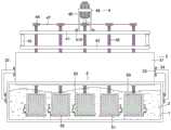
图1为本发明的结构示意图;Fig. 1 is the structural representation of the present invention;
图2为本发明甩料机构的局部结构示意图;Fig. 2 is the partial structure schematic diagram of the material rejection mechanism of the present invention;
图3为本发明盛料机构卸料时的俯视结构示意图;Fig. 3 is the top view structure schematic diagram of the material holding mechanism of the present invention when discharging;
图4为本发明挡料机构的结构示意图。FIG. 4 is a schematic structural diagram of the material blocking mechanism of the present invention.
图中:1、电镀池;2、电镀液;3、挡料机构;31、挡料框架;32、L型连接把;33、连接板;34、一号螺栓;4、甩料机构;41、一号板;42、二号板;43、支撑柱;44、轴承;45、传动杆;46、从动轮;47、传动皮带;48、伺服电机;49、固定框架;410、二号螺栓;5、盛料机构;51、盛料圆框;52、衔接杆;53、搭扣;54、铰链;55、限位圈架;56、一号过滤网;57、扭簧;58、L型搭锁;59、二号过滤网。In the figure: 1. Electroplating pool; 2. Electroplating solution; 3. Material retaining mechanism; 31. Material retaining frame; 32. L-shaped connecting handle; 33. Connecting plate; 34. No. 1 bolt; , No. 1 plate; 42, No. 2 plate; 43, support column; 44, bearing; 45, transmission rod; 46, driven wheel; 47, transmission belt; 48, servo motor; 49, fixed frame; 410, No. 2 bolt ;5, material holding mechanism; 51, material holding round frame; 52, connecting rod; 53, buckle; 54, hinge; 55, limit ring frame; 56, No. 1 filter; 57, torsion spring; 58, L Type snap; 59, No. 2 filter.
具体实施方式:Detailed ways:
如图1-4所示,本具体实施方式采用以下技术方案:电镀用圆形摇摆机构,包括电镀池1,所述电镀池1内部设置有电镀液2,所述电镀池1内部顶端上方设置有挡料机构3,所述电镀池1内部底端嵌设有若干盛料机构5,所述挡料机构3与甩料机构4贯穿相通,所述甩料机构4穿过挡料机构3的一端插入电镀池1内与其内部的若干盛料机构5固定连接。As shown in FIGS. 1-4 , this specific embodiment adopts the following technical solutions: a circular rocking mechanism for electroplating includes an
其中,所述挡料机构3包括挡料框架31、L型连接把32、连接板33以及一号螺栓34,所述挡料框架31两侧侧壁的底端均设有L型连接把32,两个所述L型连接把32靠近挡料框架31一侧的顶端以及底端均固定有连接板33,两侧的两个所述连接板33位于L型连接把32上方以及下方均插设有一号螺栓34,顶端的两个所述连接板33分别通过两个一号螺栓34与挡料框架31的两侧侧壁可拆卸连接,底端的两个所述连接板33分别通过两个一号螺栓34与电镀池1的两侧侧壁可拆卸连接,所述挡料框架31的外径尺寸小于电镀池1的内径尺寸,且所述挡料框架31的底部插设于电镀池1的内部顶端。The
其中,所述甩料机构4包括一号板41、二号板42、支撑柱43、轴承44、传动杆45、从动轮46、传动皮带47、伺服电机48、固定框架49以及二号螺栓410,所述一号板41和二号板42相互靠近的一端分别与四个支撑柱43的顶部以及底部固定连接,且四个所述支撑柱43分别与一号板41和二号板42相靠近一端的四角,所述一号板41和二号板42位于四个支撑柱43之间的内部安装有若干轴承44,所述一号板41和二号板42上的轴承44内壁分别与若干传动杆45的外壁固定连接,每个所述传动杆45的顶部均固定有从动轮46,每个所述从动轮46的外壁分别与传动皮带47的内壁套设连接,所述一号板41顶部设有固定框架49,所述固定框架49底端四角均插设有二号螺栓410,所述固定框架49的内部固定有伺服电机48,所述伺服电机48的输出端与其中一个从动轮46的顶部固定连接。The material rejection mechanism 4 includes a No. 1
其中,所述盛料机构5包括盛料圆框51、衔接杆52、搭扣53、铰链54、限位圈架55、一号过滤网56、扭簧57、L型搭锁58以及二号过滤网59,所述盛料圆框51内部固定有两个衔接杆52,每个所述传动杆45的底部分别插入每个盛料机构5的盛料圆框51内部,且与其两个衔接杆52之间的顶部固定连接,所述盛料圆框51的外壁安装有二号过滤网59,所述盛料圆框51底部一侧固定有搭扣53,所述盛料圆框51底部远离搭扣53的一侧通过铰链54与限位圈架55一侧转动连接,所述限位圈架55远离铰链54的一侧固定有扭簧57,所述扭簧57远离限位圈架55的一端固定有L型搭锁58,所述限位圈架55通过L型搭锁58与L型搭锁58转动连接,且所述L型搭锁58的位置与搭扣53的位置相匹配,且所述L型搭锁58与搭扣53挂接。The
其中,所述限位圈架55的外径尺寸等于盛料圆框51的外径尺寸,所述盛料圆框51的内径尺寸等于一号过滤网56的外径尺寸,若干所述盛料机构5中两侧盛料圆框51相互远离一侧之间的距离小于挡料框架31两侧内壁之间的距离。Wherein, the outer diameter of the
其中,所述二号板42底部至传动杆45底部之间的距离大于挡料框架31顶部至电镀池1内部底端之间的距离。Wherein, the distance from the bottom of the
具体的:使用时,通过升降设备带动本装置中的甩料机构4下降,甩料机构4通过若干传动杆45带动每个盛料机构5下降,直至每个传动杆45和盛料机构5穿过挡料框架31,并插入电镀池1内部,且盛料圆框51的顶部需在电镀池1内的高度低于电镀液2在电镀池1内的高度;电镀工作完成后,升降设备带动甩料机构4和盛料机构5上升,若干盛料机构5从电镀池1内的电镀液2中抽出,直至其上升至挡料框架31的内部后,停止升降设备的上升,伺服电机48的工作,通过从动轮46以及传动皮带47带动若干传动杆45转动,若干传动杆45带动每个盛料机构5转动,使盛料圆框51内盛放的被电镀好的配件跟着一并旋转,配件上残留的电解液通过离心力摇摆分离,通过盛料圆框51外壁的二号过滤网59将甩出的电解液甩至挡料框架31的内壁,再通过挡料框架31的限位,使其内壁的电解液顺势滑落到电镀池1内,通过限位圈架55内部的一号过滤网56,电解液直接落入电镀池1内,甩料结束后,停止伺服电机48的工作,将甩料机构4和若干盛料机构5从挡料框架31内抽出,并通过移动设备将其移动至远离电镀池1和挡料机构3的一端,进行下料工作;下料时,L型搭锁58通过扭簧57的转动,使其缩回,脱离与搭扣53的挂接限位,此时限位圈架55通过铰链54转动打开,盛料圆框51内部承载的电镀完成的配件落下,进行下料工作,下料完成后,通过铰链54的转动,使限位圈架55的顶部与盛料圆框51的底部触接,L型搭锁58与搭扣53的挂接进行对限位圈架55在盛料圆框51底部的限位,然后将需要进行电镀的配件由盛料圆框51的顶部放置进盛料圆框51内,在通过移动设备带动其移动其挡料框架31的上方,按照上述步骤,进行下一批次加工件的电镀加工工作。Specifically: when in use, the material-rejecting mechanism 4 in the device is driven to descend by the lifting device, and the material-rejecting mechanism 4 drives each material-
以上显示和描述了本发明的基本原理和主要特征和本发明的优点,本行业的技术人员应该了解,本发明不受上述实施例的限制,上述实施例和说明书中描述的只是说明本发明的原理,在不脱离本发明精神和范围的前提下,本发明还会有各种变化和改进,这些变化和改进都落入要求保护的本发明范围内,本发明要求保护范围由所附的权利要求书及其等效物界定。The basic principles, main features and advantages of the present invention are shown and described above. Those skilled in the art should understand that the present invention is not limited by the above-mentioned embodiments, and the descriptions in the above-mentioned embodiments and the description are only to illustrate the present invention. principle, on the premise of not departing from the spirit and scope of the present invention, the present invention will also have various changes and improvements, these changes and improvements all fall within the scope of the claimed invention, and the claimed scope of the present invention is determined by the appended rights Requirements and their equivalents are defined.
Claims (6)
Priority Applications (1)
| Application Number | Priority Date | Filing Date | Title |
|---|---|---|---|
| CN202010862013.5ACN111850663A (en) | 2020-08-25 | 2020-08-25 | Circular rocking mechanism for electroplating |
Applications Claiming Priority (1)
| Application Number | Priority Date | Filing Date | Title |
|---|---|---|---|
| CN202010862013.5ACN111850663A (en) | 2020-08-25 | 2020-08-25 | Circular rocking mechanism for electroplating |
Publications (1)
| Publication Number | Publication Date |
|---|---|
| CN111850663Atrue CN111850663A (en) | 2020-10-30 |
Family
ID=72967474
Family Applications (1)
| Application Number | Title | Priority Date | Filing Date |
|---|---|---|---|
| CN202010862013.5APendingCN111850663A (en) | 2020-08-25 | 2020-08-25 | Circular rocking mechanism for electroplating |
Country Status (1)
| Country | Link |
|---|---|
| CN (1) | CN111850663A (en) |
Cited By (2)
| Publication number | Priority date | Publication date | Assignee | Title |
|---|---|---|---|---|
| CN111850651A (en)* | 2020-08-25 | 2020-10-30 | 太仓舒扬博机电设备有限公司 | Aluminium anodized flying target swing device for electroplating |
| CN116397304A (en)* | 2023-03-27 | 2023-07-07 | 益阳市明正宏电子有限公司 | PCB circuit board electroplating equipment |
Citations (14)
| Publication number | Priority date | Publication date | Assignee | Title |
|---|---|---|---|---|
| DE29707027U1 (en)* | 1997-04-18 | 1997-07-17 | Alfred R. Franz Galvanotechnik, 82538 Geretsried | Loading rack for objects to be electroplated |
| US20020027080A1 (en)* | 2000-03-17 | 2002-03-07 | Junichiro Yoshioka | Plating apparatus and method |
| US20120152749A1 (en)* | 2010-12-21 | 2012-06-21 | Shingo Yasuda | Electroplating method |
| CN108149309A (en)* | 2017-12-26 | 2018-06-12 | 宁波江北清锐汽车零部件有限公司 | A kind of electroplanting device with drying functions |
| CN108545333A (en)* | 2018-06-19 | 2018-09-18 | 贵州玉屏展鸿茶叶有限公司 | A kind of screening of tealeaves and storing unit |
| EP3415051A1 (en)* | 2017-06-12 | 2018-12-19 | Vorwerk & Co. Interholding GmbH | System for handling a tea strainer insert and handle and tea machine for same |
| CN110117811A (en)* | 2019-06-26 | 2019-08-13 | 王宏斌 | A kind of plating treatment apparatus |
| CN110235836A (en)* | 2019-06-25 | 2019-09-17 | 赖虔忠 | A kind of feeding lobster feeding ship in lotus rhizome pond |
| CN110373702A (en)* | 2019-08-13 | 2019-10-25 | 何桂华 | It is a kind of with the electroplating system to feed intake with agitating function |
| CN110541185A (en)* | 2019-07-24 | 2019-12-06 | 扬州市佳佳镀锌有限公司 | High-efficient type electroplating device with edulcoration function |
| CN110592646A (en)* | 2019-07-24 | 2019-12-20 | 扬州市佳佳镀锌有限公司 | Environment-friendly barrel plating equipment with high electroplating quality |
| CN209861661U (en)* | 2019-04-26 | 2019-12-31 | 江苏徐淮地区徐州农业科学研究所(江苏徐州甘薯研究中心) | Novel agitator tank structure for agricultural thresher |
| CN209941131U (en)* | 2019-04-19 | 2020-01-14 | 扬州丽致机械设备制造有限公司 | Rotary type automatic discharging electroplating drum |
| CN212476928U (en)* | 2020-08-25 | 2021-02-05 | 太仓舒扬博机电设备有限公司 | Circular rocking mechanism for electroplating |
- 2020
- 2020-08-25CNCN202010862013.5Apatent/CN111850663A/enactivePending
Patent Citations (14)
| Publication number | Priority date | Publication date | Assignee | Title |
|---|---|---|---|---|
| DE29707027U1 (en)* | 1997-04-18 | 1997-07-17 | Alfred R. Franz Galvanotechnik, 82538 Geretsried | Loading rack for objects to be electroplated |
| US20020027080A1 (en)* | 2000-03-17 | 2002-03-07 | Junichiro Yoshioka | Plating apparatus and method |
| US20120152749A1 (en)* | 2010-12-21 | 2012-06-21 | Shingo Yasuda | Electroplating method |
| EP3415051A1 (en)* | 2017-06-12 | 2018-12-19 | Vorwerk & Co. Interholding GmbH | System for handling a tea strainer insert and handle and tea machine for same |
| CN108149309A (en)* | 2017-12-26 | 2018-06-12 | 宁波江北清锐汽车零部件有限公司 | A kind of electroplanting device with drying functions |
| CN108545333A (en)* | 2018-06-19 | 2018-09-18 | 贵州玉屏展鸿茶叶有限公司 | A kind of screening of tealeaves and storing unit |
| CN209941131U (en)* | 2019-04-19 | 2020-01-14 | 扬州丽致机械设备制造有限公司 | Rotary type automatic discharging electroplating drum |
| CN209861661U (en)* | 2019-04-26 | 2019-12-31 | 江苏徐淮地区徐州农业科学研究所(江苏徐州甘薯研究中心) | Novel agitator tank structure for agricultural thresher |
| CN110235836A (en)* | 2019-06-25 | 2019-09-17 | 赖虔忠 | A kind of feeding lobster feeding ship in lotus rhizome pond |
| CN110117811A (en)* | 2019-06-26 | 2019-08-13 | 王宏斌 | A kind of plating treatment apparatus |
| CN110592646A (en)* | 2019-07-24 | 2019-12-20 | 扬州市佳佳镀锌有限公司 | Environment-friendly barrel plating equipment with high electroplating quality |
| CN110541185A (en)* | 2019-07-24 | 2019-12-06 | 扬州市佳佳镀锌有限公司 | High-efficient type electroplating device with edulcoration function |
| CN110373702A (en)* | 2019-08-13 | 2019-10-25 | 何桂华 | It is a kind of with the electroplating system to feed intake with agitating function |
| CN212476928U (en)* | 2020-08-25 | 2021-02-05 | 太仓舒扬博机电设备有限公司 | Circular rocking mechanism for electroplating |
Cited By (3)
| Publication number | Priority date | Publication date | Assignee | Title |
|---|---|---|---|---|
| CN111850651A (en)* | 2020-08-25 | 2020-10-30 | 太仓舒扬博机电设备有限公司 | Aluminium anodized flying target swing device for electroplating |
| CN111850651B (en)* | 2020-08-25 | 2025-04-15 | 深圳市新富华表面技术有限公司 | Aluminum anodizing target swing device for electroplating |
| CN116397304A (en)* | 2023-03-27 | 2023-07-07 | 益阳市明正宏电子有限公司 | PCB circuit board electroplating equipment |
Similar Documents
| Publication | Publication Date | Title |
|---|---|---|
| CN111850663A (en) | Circular rocking mechanism for electroplating | |
| CN116130821B (en) | Wet recycling device for lithium iron phosphate battery and application method of wet recycling device | |
| CN212476928U (en) | Circular rocking mechanism for electroplating | |
| CN116988132A (en) | Gantry barrel plating device | |
| CN109046870A (en) | A kind of the dacroment process dip-coating centrifugation all-in-one machine | |
| CN110552050A (en) | Barrel-plating device for hardware part machining | |
| CN206138836U (en) | Hybrid processing device that combined material system filtration membrane used | |
| CN221223173U (en) | Layered dryer for tea processing | |
| CN104175713A (en) | Ink circulating device with automatic stirring function | |
| CN210966133U (en) | Tea leaf cleaning device | |
| CN210752285U (en) | Full-automatic dye preparation system | |
| CN212018699U (en) | Magnetic material screening and cleaning device | |
| CN209597545U (en) | A dip-coating centrifuge integrated machine for dacromet treatment | |
| CN223422477U (en) | Feeding equipment for sewage treatment | |
| CN223118507U (en) | A mechanical parts quenching device | |
| CN111468003A (en) | Device for replacing artificial intelligence to stir building stones and placing method | |
| CN219072133U (en) | Extraction element is used in chinese-medicinal material processing | |
| CN112426800A (en) | Acid liquor collecting device for polar plate production | |
| CN221135462U (en) | Grinding machine | |
| CN221249344U (en) | Building engineering material mixes configuration device | |
| CN210752498U (en) | Fluorescent paint preparation facilities | |
| CN215089369U (en) | Belt cleaning device is used in chinese-medicinal material production convenient to pay-off in batches | |
| CN223226211U (en) | Electroplating tank for electroplating processing | |
| CN219174647U (en) | Barrel plating production line | |
| CN222158551U (en) | Conveying equipment convenient to adjust and used for solid waste resource management |
Legal Events
| Date | Code | Title | Description |
|---|---|---|---|
| PB01 | Publication | ||
| PB01 | Publication | ||
| SE01 | Entry into force of request for substantive examination | ||
| SE01 | Entry into force of request for substantive examination |