CN111843678A - A wood furniture grinding device - Google Patents
A wood furniture grinding deviceDownload PDFInfo
- Publication number
- CN111843678A CN111843678ACN202010500257.9ACN202010500257ACN111843678ACN 111843678 ACN111843678 ACN 111843678ACN 202010500257 ACN202010500257 ACN 202010500257ACN 111843678 ACN111843678 ACN 111843678A
- Authority
- CN
- China
- Prior art keywords
- grinding
- workbench
- module
- block
- sliding block
- Prior art date
- Legal status (The legal status is an assumption and is not a legal conclusion. Google has not performed a legal analysis and makes no representation as to the accuracy of the status listed.)
- Granted
Links
- 239000002023woodSubstances0.000titleclaimsabstractdescription43
- 239000003638chemical reducing agentSubstances0.000claimsdescription9
- 239000000428dustSubstances0.000claimsdescription7
- 238000005498polishingMethods0.000claimsdescription6
- 230000000149penetrating effectEffects0.000claims1
- 238000000034methodMethods0.000abstractdescription7
- 230000008569processEffects0.000abstractdescription6
- 230000009471actionEffects0.000abstractdescription3
- XLYOFNOQVPJJNP-UHFFFAOYSA-NwaterSubstancesOXLYOFNOQVPJJNP-UHFFFAOYSA-N0.000abstractdescription3
- 239000002245particleSubstances0.000description6
- 230000004048modificationEffects0.000description3
- 238000012986modificationMethods0.000description3
- 239000000843powderSubstances0.000description3
- 238000005034decorationMethods0.000description2
- 238000010586diagramMethods0.000description2
- 238000004519manufacturing processMethods0.000description2
- 230000009286beneficial effectEffects0.000description1
- 230000008859changeEffects0.000description1
- 230000000694effectsEffects0.000description1
- 230000006872improvementEffects0.000description1
- 239000007787solidSubstances0.000description1
Images


Classifications
- B—PERFORMING OPERATIONS; TRANSPORTING
- B24—GRINDING; POLISHING
- B24B—MACHINES, DEVICES, OR PROCESSES FOR GRINDING OR POLISHING; DRESSING OR CONDITIONING OF ABRADING SURFACES; FEEDING OF GRINDING, POLISHING, OR LAPPING AGENTS
- B24B7/00—Machines or devices designed for grinding plane surfaces on work, including polishing plane glass surfaces; Accessories therefor
- B24B7/20—Machines or devices designed for grinding plane surfaces on work, including polishing plane glass surfaces; Accessories therefor characterised by a special design with respect to properties of the material of non-metallic articles to be ground
- B24B7/28—Machines or devices designed for grinding plane surfaces on work, including polishing plane glass surfaces; Accessories therefor characterised by a special design with respect to properties of the material of non-metallic articles to be ground for grinding wood
- B—PERFORMING OPERATIONS; TRANSPORTING
- B24—GRINDING; POLISHING
- B24B—MACHINES, DEVICES, OR PROCESSES FOR GRINDING OR POLISHING; DRESSING OR CONDITIONING OF ABRADING SURFACES; FEEDING OF GRINDING, POLISHING, OR LAPPING AGENTS
- B24B41/00—Component parts such as frames, beds, carriages, headstocks
- B24B41/02—Frames; Beds; Carriages
- B—PERFORMING OPERATIONS; TRANSPORTING
- B24—GRINDING; POLISHING
- B24B—MACHINES, DEVICES, OR PROCESSES FOR GRINDING OR POLISHING; DRESSING OR CONDITIONING OF ABRADING SURFACES; FEEDING OF GRINDING, POLISHING, OR LAPPING AGENTS
- B24B5/00—Machines or devices designed for grinding surfaces of revolution on work, including those which also grind adjacent plane surfaces; Accessories therefor
- B24B5/50—Machines or devices designed for grinding surfaces of revolution on work, including those which also grind adjacent plane surfaces; Accessories therefor characterised by a special design with respect to properties of the material of non-metallic articles to be ground, e.g. strings
Landscapes
- Engineering & Computer Science (AREA)
- Mechanical Engineering (AREA)
- Life Sciences & Earth Sciences (AREA)
- Wood Science & Technology (AREA)
- Finish Polishing, Edge Sharpening, And Grinding By Specific Grinding Devices (AREA)
Abstract
Translated fromChinese
Description
Translated fromChinese技术领域technical field
本说明书一个或多个实施例涉及家具生产设备技术领域,尤其涉及一种木式家具打磨装置。One or more embodiments of this specification relate to the technical field of furniture production equipment, and in particular, to a wood furniture grinding device.
背景技术Background technique
木式家具一般用作高档装饰,对于木材的处理需要进行多道工序,特别是需要进行细致地打磨,从而使木材的纹理能够充分展现;通常在进行打磨时,需要技术工人采用人工打磨的方式;使用打磨工具沿着木材的纹理方向对表面进行单一方向的打磨,但人工打磨效率较低,从而使成本增加,需要一种装置能够模仿人工打磨的方式替代人工打磨,从而节省人力,提高生产效率。Wooden furniture is generally used for high-end decoration, and the treatment of wood requires multiple processes, especially careful grinding, so that the texture of the wood can be fully displayed; usually, when grinding, skilled workers are required to use manual grinding. ;Use a grinding tool to grind the surface in a single direction along the grain direction of the wood, but the efficiency of manual grinding is low, which increases the cost, and a device that can imitate manual grinding is needed to replace manual grinding, thereby saving manpower and improving production. efficiency.
发明内容SUMMARY OF THE INVENTION
有鉴于此,本说明书一个或多个实施例的目的在于提出一种木式家具打磨装置,以解决背景技术中提出的问题。In view of this, the purpose of one or more embodiments of the present specification is to provide a wood furniture grinding device to solve the problems raised in the background art.
基于上述目的,本说明书一个或多个实施例提供了一种木式家具打磨装置,包括:Based on the above purpose, one or more embodiments of the present specification provide a wooden furniture grinding device, including:
机架;frame;
工作台,装设于所述机架上,上端面为水平台面,上端面上装设有夹持块;The workbench is installed on the frame, the upper end surface is a water platform surface, and a clamping block is installed on the upper end surface;
支架组件,装设于所述机架上,包括竖直设置的支架,所述支架的上端装设有沿所述工作台长度方向设置的滑轨;a bracket assembly, installed on the frame, including a vertically arranged bracket, the upper end of the bracket is equipped with a slide rail arranged along the length direction of the workbench;
打磨组件,装设于所述支架的上端,包括滑块,所述滑块滑动装设于所述滑轨上,所述滑块在靠近所述工作台的一侧端面上设置有伸缩件,所述伸缩件在靠近所述工作台的一端装设有打磨模块;The grinding assembly is installed on the upper end of the bracket, and includes a slider, the slider is slidably installed on the slide rail, and the slider is provided with a telescopic piece on the end surface of one side close to the worktable, A grinding module is installed at one end of the telescopic piece close to the worktable;
控制组件,包括传感模块与控制模块,所述传感模块固定装设于所述滑轨的侧壁上,所述控制模块固定装设于所述机架上;a control assembly, including a sensing module and a control module, the sensing module is fixedly installed on the side wall of the slide rail, and the control module is fixedly installed on the rack;
驱动组件,固定装设于所述机架的上端,与所述控制模块电性连接,能够驱动所述滑块移动。The driving component is fixedly installed on the upper end of the frame, is electrically connected with the control module, and can drive the sliding block to move.
可选的,所述工作台的上端面沿所述工作台的长度方向开设有多条相互平行的第一凹槽,所述第一凹槽的开口方向远离所述工作台的中心,所述第一凹槽在开口处设置有凸缘,所述第一凹槽内活动装设有多个移动块,所述移动块与所述第一凹槽相匹配,所述移动块的上端面竖直装设有螺纹杆。Optionally, a plurality of mutually parallel first grooves are provided on the upper end surface of the worktable along the length direction of the worktable, and the opening direction of the first grooves is away from the center of the worktable. The first groove is provided with a flange at the opening, a plurality of moving blocks are movably installed in the first groove, the moving blocks are matched with the first groove, and the upper end surface of the moving block is vertical Straight mount with threaded rod.
可选的,所述夹持块的截面为L形,包括杆部与夹持部,夹持部长度小于杆部,且与杆部垂直设置,杆部的端面上沿长度方向贯穿开设有通孔。Optionally, the cross-section of the clamping block is L-shaped, including a rod part and a clamping part, the clamping part is shorter than the rod part, and is perpendicular to the rod part, and the end surface of the rod part is provided with a through hole along the length direction. hole.
可选的,所述第一凹槽的两侧内壁上开设有多个吸风口,所述吸风口连通装设有吸尘模块。Optionally, a plurality of air suction openings are opened on the inner walls of both sides of the first groove, and a dust suction module is connected and installed with the air suction openings.
可选的,所述滑块的侧壁上贯穿开设有通槽,所述通槽的内壁轮廓与所述滑轨的外壁轮廓相匹配,所述通槽的内壁上装设有传感器,所述滑轨的外壁上可拆卸地装设有两个信号发生器,所述信号发生器设置于所述传感器移动路径的首尾两端,两个所述信号发生器的间距可调。Optionally, a through slot is formed through the side wall of the slider, the inner wall contour of the through slot matches the outer wall contour of the slide rail, a sensor is installed on the inner wall of the through slot, and the slide Two signal generators are detachably mounted on the outer wall of the rail, the signal generators are arranged at the beginning and the end of the moving path of the sensor, and the distance between the two signal generators is adjustable.
可选的,所述滑轨的下端面上开设有沿所述滑轨长度方向设置的第二凹槽,所述第二凹槽的开口方向朝向所述工作台的上端面,所述第二凹槽的一侧内壁上开设有齿面,所述齿面上啮合装设有齿轮,所述齿轮的下端面装设有转动轴,所述转动轴竖直贯穿所述滑块的下端面,所述转动轴在远离所述齿轮的一端固定装设有圆盘,所述圆盘的下端面装设有刷毛。Optionally, the lower end surface of the slide rail is provided with a second groove arranged along the length direction of the slide rail, and the opening direction of the second groove faces the upper end surface of the workbench, and the second groove A tooth surface is opened on one inner wall of the groove, a gear is meshed on the tooth surface, a rotating shaft is installed on the lower end surface of the gear, and the rotating shaft vertically penetrates the lower end surface of the sliding block. A disc is fixedly installed on the end of the rotating shaft away from the gear, and bristles are installed on the lower end surface of the disc.
可选的,所述伸缩件具有固定端与伸缩端,所述打磨模块包括对称装设于所述伸缩件两侧的摆动臂,所述摆动臂的顶端与固定端的侧壁连接装设有伸缩弹簧,所述摆动臂的侧壁与固定端的侧壁间装设有第一连杆,与伸缩端的侧壁间铰接装设有第二连杆,所述第一连杆设于所述第二连杆的上方,所述摆动臂的下端铰接装设有打磨块,伸缩端的下端面上固定装设有打磨块。Optionally, the telescopic piece has a fixed end and a telescopic end, the grinding module includes swing arms symmetrically installed on both sides of the telescopic piece, and the top end of the swing arm is connected to the side wall of the fixed end with a telescopic arm. A spring, a first link is installed between the side wall of the swing arm and the side wall of the fixed end, and a second link is hingedly installed with the side wall of the telescopic end, and the first link is arranged on the second link. Above the connecting rod, a grinding block is hingedly mounted on the lower end of the swing arm, and a grinding block is fixedly mounted on the lower end surface of the telescopic end.
可选的,所述工作台的下端装设有移动模块,所述移动模块包括沿所述工作台长度方向设置的丝杠,所述工作台的下端套装于所述丝杠的外壁上。Optionally, a moving module is installed at the lower end of the working table, the moving module includes a lead screw arranged along the length direction of the working platform, and the lower end of the working platform is sleeved on the outer wall of the lead screw.
可选的,所述支架的上端固定装设有驱动电机,所述驱动电机的转动轴连接装设有减速器,所述减速器的输出端固定装设有第一摇杆,所述第一摇杆在远离所述减速器的一端铰接装设有第二摇杆,所述第二摇杆的另一端与所述滑块的侧壁铰接设置。Optionally, a drive motor is fixedly installed on the upper end of the bracket, a reducer is connected to the rotating shaft of the drive motor, and a first rocker is fixedly installed at the output end of the reducer. A second rocker is hingedly arranged at one end of the rocker away from the speed reducer, and the other end of the second rocker is hingedly arranged with the side wall of the slider.
有益效果:Beneficial effects:
1.为了保证实木家具的纹理能够清晰呈现,设置有滑轨和打磨组件,能够使打磨过程按照单方向移动打磨,打磨块在完成打磨动作时,打磨头在伸缩件的推动下,贴合木材表面移动;当打磨块收回时,伸缩件带动打磨块离开木材表面;通过伸缩件带动打磨块上下移动,打磨块能够循环地完成单方向打磨,从而更好得呈现木材的纹理。1. In order to ensure that the texture of solid wood furniture can be clearly presented, there are slide rails and grinding components, which can make the grinding process move and grind in one direction. When the grinding block completes the grinding action, the grinding head is pushed by the telescopic piece to fit the wood. The surface moves; when the grinding block is retracted, the telescopic piece drives the grinding block away from the wood surface; the grinding block is driven up and down by the telescopic piece, and the grinding block can cyclically complete one-way grinding, so as to better present the wood texture.
2.本装置不仅仅需要对板材进行打磨,也需要对杆状木材进行打磨,为了提升本装置的打磨效果,设置有摆动臂、第一连杆和第二连杆,伸缩端下降时,摆动臂带动打磨块夹持在杆状木材的两侧,从而实现对板材的多面打磨,提高打磨效率。2. The device not only needs to grind the plate, but also needs to grind the rod-shaped wood. In order to improve the grinding effect of the device, a swing arm, a first link and a second link are provided. The arm drives the grinding blocks to be clamped on both sides of the rod-shaped wood, so as to realize multi-face grinding of the board and improve the grinding efficiency.
附图说明Description of drawings
为了更清楚地说明本说明书一个或多个实施例或现有技术中的技术方案,下面将对实施例或现有技术描述中所需要使用的附图作简单地介绍,显而易见地,下面描述中的附图仅仅是本说明书一个或多个实施例,对于本领域普通技术人员来讲,在不付出创造性劳动的前提下,还可以根据这些附图获得其他的附图。In order to more clearly illustrate one or more embodiments of the present specification or the technical solutions in the prior art, the following briefly introduces the accompanying drawings used in the description of the embodiments or the prior art. Obviously, in the following description The accompanying drawings are only one or more embodiments of the present specification, and for those of ordinary skill in the art, other drawings can also be obtained from these drawings without any creative effort.
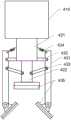
图1为本说明书一个或多个实施例木式家具打磨装置的整体结构示意图;1 is a schematic diagram of the overall structure of a wooden furniture grinding device according to one or more embodiments of this specification;
图2为本说明书一个或多个实施例木式家具打磨装置中打磨模块的结构示意图;2 is a schematic structural diagram of a grinding module in a wooden furniture grinding device according to one or more embodiments of this specification;
图3为本说明书一个或多个实施例木式家具打磨装置中滑块的剖面示意图;3 is a schematic cross-sectional view of a slider in a wooden furniture grinding device according to one or more embodiments of the present specification;
图4为图1中A-A的剖面示意图。FIG. 4 is a schematic cross-sectional view of A-A in FIG. 1 .
具体实施方式Detailed ways
为使本公开的目的、技术方案和优点更加清楚明白,以下结合具体实施例,对本公开进一步详细说明。In order to make the objectives, technical solutions and advantages of the present disclosure clearer, the present disclosure will be further described in detail below with reference to specific embodiments.
需要说明的是,除非另外定义,本说明书一个或多个实施例使用的技术术语或者科学术语应当为本公开所属领域内具有一般技能的人士所理解的通常意义。本说明书一个或多个实施例中使用的“第一”、“第二”以及类似的词语并不表示任何顺序、数量或者重要性,而只是用来区分不同的组成部分。“包括”或者“包含”等类似的词语意指出现该词前面的元件或者物件涵盖出现在该词后面列举的元件或者物件及其等同,而不排除其他元件或者物件。“连接”或者“相连”等类似的词语并非限定于物理的或者机械的连接,而是可以包括电性的连接,不管是直接的还是间接的。“上”、“下”、“左”、“右”等仅用于表示相对位置关系,当被描述对象的绝对位置改变后,则该相对位置关系也可能相应地改变。It should be noted that, unless otherwise defined, the technical or scientific terms used in one or more embodiments of the present specification shall have the usual meanings understood by those with ordinary skill in the art to which this disclosure belongs. The terms "first," "second," and similar terms used in one or more embodiments of this specification do not denote any order, quantity, or importance, but are merely used to distinguish the various components. "Comprises" or "comprising" and similar words mean that the elements or things appearing before the word encompass the elements or things recited after the word and their equivalents, but do not exclude other elements or things. Words like "connected" or "connected" are not limited to physical or mechanical connections, but may include electrical connections, whether direct or indirect. "Up", "Down", "Left", "Right", etc. are only used to represent the relative positional relationship, and when the absolute position of the described object changes, the relative positional relationship may also change accordingly.
如图1至图4所示,本说明书提供了一种木式家具打磨装置,包括:As shown in Figures 1 to 4, this specification provides a wooden furniture grinding device, including:
机架1,固定安装在地面上,用于放置本装置各部分零件;Rack 1, fixedly installed on the ground, used to place all parts of the device;
工作台2,活动装设于机架1上,上端面为水平台面,用于放置需要打磨的木材,上端面上装设有夹持块210,夹持块210夹持在木材的两端,用于固定;The
支架组件3,下端通过螺栓固定在机架1上,包括竖直设置的支架310,支架310的上端装设有沿工作台2长度方向设置的滑轨320;The
打磨组件4,装设于支架310的上端,包括滑块410,滑块410滑动装设于滑轨320上,滑块410在靠近工作台2的一侧端面上设置有伸缩件420,伸缩件420在靠近工作台2的一端装设有打磨模块430,使用时,滑块410首先按照一定的方向移动,在移动过程中,伸缩件420推动打磨模块430向工作台2方向运动,打磨模块430与木材的被打磨面相贴合,随着滑块410在滑轨320上缓慢移动,实现打磨模块430对木材表面打磨;滑块410在收回的过程中,打磨模块430通过伸缩件420向上提升,与木材的被打磨面相分离。The
控制组件5,包括传感模块510与控制模块520,传感模块510固定装设于滑轨320的侧壁上,控制模块520固定装设于机架1上,传感模块510用以测定滑块410的行程,从而使控制模块520准确控制打磨模块430的升降;The
驱动组件6,固定装设于机架1的上端,与控制模块520电性连接,能够驱动滑块410在滑轨320上往复移动。The
木式家具一般用作高档装饰,为了保证木质纹理能够清晰呈现,设置有滑轨320和打磨组件4,能够使打磨过程按照单方向移动打磨,打磨模块430在完成打磨动作时,打磨头在伸缩件420的推动下,贴合木材表面移动;当打磨块收回时,伸缩件420带动打磨块离开木材表面;通过伸缩件420带动打磨块上下移动,打磨块能够循环地完成单方向打磨,从而更好得呈现木材的纹理。Wooden furniture is generally used for high-end decoration. In order to ensure that the wood texture can be clearly presented, a
进一步地,工作台2的上端面沿工作台2的长度方向开设有多条相互平行的第一凹槽220,第一凹槽220的开口方向远离工作台2的中心,第一凹槽220在开口处设置有凸缘,第一凹槽220内活动装设有多个移动块230,移动块230与第一凹槽220相匹配,移动块230的上端面竖直装设有螺纹杆231,其中移动块230可根据被打磨木材的形状来调节位置,从而可以适应不同形状的木材,使之可以固定牢固。Further, the upper end surface of the
进一步地,夹持块210的截面为L形,包括杆部211与夹持部212,夹持部212长度小于杆部211,且与杆部211垂直设置,杆部211的端面上沿长度方向贯穿开设有通孔,在使用时,杆部211通过通孔套装在螺纹杆231上,夹持部212位于远离移动块230的一端,用于对木材施加夹持力,螺纹杆231上设置调节螺母,从而调节夹持块210的高度。Further, the cross-section of the
进一步地,第一凹槽220的两侧内壁上开设有多个吸风口221,吸风口221连通装设有吸尘模块7,在打磨过程中,会产生灰尘颗粒,落入到第一凹槽220中后,通过吸尘模块7将灰尘颗粒吸入吸风口221,总而便于收集,避免灰尘颗粒污染环境。Further, a plurality of
进一步地,滑块410的侧壁上沿滑轨320的长度方向贯穿开设有通槽411,通槽411的内壁轮廓与滑轨320的外壁轮廓相匹配,通槽411的内壁上装设有传感器512,滑轨320的外壁上可拆卸地装设有两个信号发生器511,信号发生器511设置于传感器512移动路径的首尾两端,两个信号发生器511的间距可调;当滑块410由初始位置运动,带动传感器512经过第一个信号发生器511时,产生信号并传输至控制模块520中,控制模块520控制伸缩件420推动打磨模块430下降,使打磨模块430与被打磨面紧密贴合,随着滑块410继续在滑轨320上移动,打磨模块430对被打磨面提供稳定且均匀的摩擦力;当滑块410移动到行程末端时,传感器512接受到第二个信号发生器511的信号,从而通过控制模块520发出指令,使伸缩件420带动打磨模块430上升,从而离开被打磨面;同时滑块410在移动到行程末端后,会沿着滑轨320回到起始位置,当传感器512到达起始位置后,接受到第一个信号发生器511的信号后,伸缩件430重新推动打磨模块430与被打磨面相贴合,从而实现单向打磨,使木材呈现出完整清晰的纹理。Further, a through
进一步地,滑轨320的下端面上开设有沿滑轨320长度方向设置的第二凹槽321,第二凹槽321的开口方向朝向工作台2的上端面,第二凹槽321的一侧内壁上开设有齿面,齿面上啮合装设有齿轮441,齿轮441的下端面装设有转动轴442,转动轴442竖直贯穿滑块410的下端面,转动轴442在远离齿轮441的一端固定装设有圆盘443,圆盘443的下端面装设有刷毛444,由于被打磨面上堆积大量粉末颗粒后,会导致打磨效率降低,因此需要及时将粉末颗粒清除,随着滑块410在滑轨320上往复移动,齿轮441在第二凹槽321内与齿面啮合,从而带动下端的转动轴442转动,转动轴442下端的圆盘443随转动轴442转动,从而带动刷毛444清除被打磨面上的粉末颗粒。Further, the lower end surface of the
在一种可选实施例中,该装置需要对杆状木材进行打磨,为保证打磨的效率与打磨质量,设置伸缩件420具有固定端421与伸缩端422,固定端421的上端通过螺栓连接的方式固定安装在滑块410的下端面上;In an optional embodiment, the device needs to grind rod-shaped wood. In order to ensure the grinding efficiency and grinding quality, the
打磨模块430包括对称装设于伸缩件420两侧的摆动臂431,摆动臂431的顶端与固定端421的侧壁连接装设有伸缩弹簧434,摆动臂431的侧壁与固定端421的侧壁间装设有第一连杆432,第一连杆432与固定端421连接的一侧固定安装,摆动臂431与伸缩端422的侧壁间铰接装设有第二连杆433,第一连杆432设于第二连杆433的上方,摆动臂431的下端铰接装设有打磨块435,伸缩端422的下端面上固定装设有打磨块435,在使用时,随着伸缩端422下降,带动第二连杆433下降,从而带动摆动臂431绕第一连杆432转动,摆动臂431端部的打磨块435将杆状木材的两侧夹紧,从而增加与木材的接触面积,随着滑块410在滑轨320上移动,实现对杆状木材的多面打磨,提升打磨效率,同时使打磨程度一致,从而使木材打磨均匀,提升打磨质量。The grinding
进一步地,工作台2的下端装设有移动模块,移动模块包括沿工作台长度方向设置的丝杠240,工作台2的下端套装于丝杠240的外壁上,在使用时,通过丝杠240的转动,可以对工作台2的位置进行调整;优选的采用电机驱动丝杠240转动。Further, the lower end of the
进一步地,支架310的上端固定装设有驱动电机610,驱动电机610的转动轴连接装设有减速器,减速器的输出端固定装设有第一摇杆621,第一摇杆621在远离减速器的一端铰接装设有第二摇杆622,第二摇杆622的另一端与滑块410的侧壁铰接设置,通过第一摇杆621与第二摇杆622组合使用,可以使滑块410在滑轨320上往复运动。Further, a
本发明的具体工作原理:驱动模块6通过驱动第一摇杆621与第二摇杆622摆动,从而使滑块410在滑轨320上做往复运动;The specific working principle of the present invention: the
传感模块510包括安装在滑块410上的传感器512和安装在滑轨上的两个信号发生器511,分别安装在滑块410移动的起始位置与终止位置,传感器512经过第一个信号发生器511时,接收信号并通过控制模块520控制伸缩件420推动打磨模块430与被打磨面相贴合,随着滑块410移动完成对木材的打磨;当滑块410移动到终止位置时,第二个信号发生器511的信号被传感器512接收,并通过控制模块520提升打磨模块430,使之离开被打磨面,同时滑块410从终止位置向初始位置移动;The
伸缩端422向下移动时,第二连杆433带动摆动臂431绕第一连杆432转动,从而使摆动臂431端部的打磨块435与被打磨的杆状木材的侧壁相贴合。When the
所属领域的普通技术人员应当理解:以上任何实施例的讨论仅为示例性的,并非旨在暗示本公开的范围(包括权利要求)被限于这些例子;在本公开的思路下,以上实施例或者不同实施例中的技术特征之间也可以进行组合,步骤可以以任意顺序实现,并存在如上所述的本说明书一个或多个实施例的不同方面的许多其它变化,为了简明它们没有在细节中提供。It should be understood by those of ordinary skill in the art that the discussion of any of the above embodiments is only exemplary, and is not intended to imply that the scope of the present disclosure (including the claims) is limited to these examples; under the spirit of the present disclosure, the above embodiments or Technical features in different embodiments may also be combined, steps may be carried out in any order, and there are many other variations of the different aspects of one or more embodiments of this specification as described above, which are not in detail for the sake of brevity supply.
尽管已经结合了本公开的具体实施例对本公开进行了描述,但是根据前面的描述,这些实施例的很多替换、修改和变型对本领域普通技术人员来说将是显而易见的。Although the present disclosure has been described in conjunction with specific embodiments thereof, many alternatives, modifications, and variations to these embodiments will be apparent to those of ordinary skill in the art from the foregoing description.
本说明书一个或多个实施例旨在涵盖落入所附权利要求的宽泛范围之内的所有这样的替换、修改和变型。因此,凡在本说明书一个或多个实施例的精神和原则之内,所做的任何省略、修改、等同替换、改进等,均应包含在本公开的保护范围之内。The embodiment or embodiments of this specification are intended to cover all such alternatives, modifications and variations that fall within the broad scope of the appended claims. Therefore, any omission, modification, equivalent replacement, improvement, etc. made within the spirit and principle of one or more embodiments of the present specification should be included within the protection scope of the present disclosure.
Claims (9)
Priority Applications (1)
| Application Number | Priority Date | Filing Date | Title |
|---|---|---|---|
| CN202010500257.9ACN111843678B (en) | 2020-06-04 | 2020-06-04 | Wooden furniture grinding device |
Applications Claiming Priority (1)
| Application Number | Priority Date | Filing Date | Title |
|---|---|---|---|
| CN202010500257.9ACN111843678B (en) | 2020-06-04 | 2020-06-04 | Wooden furniture grinding device |
Publications (2)
| Publication Number | Publication Date |
|---|---|
| CN111843678Atrue CN111843678A (en) | 2020-10-30 |
| CN111843678B CN111843678B (en) | 2021-12-31 |
Family
ID=72985877
Family Applications (1)
| Application Number | Title | Priority Date | Filing Date |
|---|---|---|---|
| CN202010500257.9AActiveCN111843678B (en) | 2020-06-04 | 2020-06-04 | Wooden furniture grinding device |
Country Status (1)
| Country | Link |
|---|---|
| CN (1) | CN111843678B (en) |
Cited By (3)
| Publication number | Priority date | Publication date | Assignee | Title |
|---|---|---|---|---|
| CN112692673A (en)* | 2020-12-24 | 2021-04-23 | 上海钢度电子商务有限公司 | Processing device for removing burrs in steel transportation |
| CN114464029A (en)* | 2021-05-14 | 2022-05-10 | 淮阴工学院 | Language teaching device |
| CN117921488A (en)* | 2024-03-25 | 2024-04-26 | 宿迁市永峰智能家居有限公司 | Automatic polishing device for furniture production |
Citations (4)
| Publication number | Priority date | Publication date | Assignee | Title |
|---|---|---|---|---|
| EP2123396A1 (en)* | 2008-05-22 | 2009-11-25 | Marino Angeloni | Smoothing/brushing machine for wooden articles and relative operating method |
| CN108161618A (en)* | 2017-12-18 | 2018-06-15 | 曾强 | A kind of constructing tunnel pipe edge grinding apparatus |
| CN209364305U (en)* | 2018-11-22 | 2019-09-10 | 天津品辉木业有限公司 | A kind of intelligent grinding device of timber carving |
| CN210046459U (en)* | 2019-02-13 | 2020-02-11 | 中山市玛斯特展示制品有限公司 | Well island cabinet polishing equipment of polishing |
- 2020
- 2020-06-04CNCN202010500257.9Apatent/CN111843678B/enactiveActive
Patent Citations (4)
| Publication number | Priority date | Publication date | Assignee | Title |
|---|---|---|---|---|
| EP2123396A1 (en)* | 2008-05-22 | 2009-11-25 | Marino Angeloni | Smoothing/brushing machine for wooden articles and relative operating method |
| CN108161618A (en)* | 2017-12-18 | 2018-06-15 | 曾强 | A kind of constructing tunnel pipe edge grinding apparatus |
| CN209364305U (en)* | 2018-11-22 | 2019-09-10 | 天津品辉木业有限公司 | A kind of intelligent grinding device of timber carving |
| CN210046459U (en)* | 2019-02-13 | 2020-02-11 | 中山市玛斯特展示制品有限公司 | Well island cabinet polishing equipment of polishing |
Cited By (5)
| Publication number | Priority date | Publication date | Assignee | Title |
|---|---|---|---|---|
| CN112692673A (en)* | 2020-12-24 | 2021-04-23 | 上海钢度电子商务有限公司 | Processing device for removing burrs in steel transportation |
| CN114464029A (en)* | 2021-05-14 | 2022-05-10 | 淮阴工学院 | Language teaching device |
| CN114464029B (en)* | 2021-05-14 | 2023-09-22 | 淮阴工学院 | a language teaching device |
| CN117921488A (en)* | 2024-03-25 | 2024-04-26 | 宿迁市永峰智能家居有限公司 | Automatic polishing device for furniture production |
| CN117921488B (en)* | 2024-03-25 | 2024-05-24 | 宿迁市永峰智能家居有限公司 | Automatic polishing device for furniture production |
Also Published As
| Publication number | Publication date |
|---|---|
| CN111843678B (en) | 2021-12-31 |
Similar Documents
| Publication | Publication Date | Title |
|---|---|---|
| CN111843678A (en) | A wood furniture grinding device | |
| CN207239843U (en) | One kind finishing uses ceramic floor sanding apparatus | |
| TW201521961A (en) | One kind of gantry milling bodies and the application of its automatic grinding machine | |
| CN207448119U (en) | A kind of entire body marble sanding apparatus | |
| CN111266961A (en) | Cambered surface grinding device | |
| CN209062729U (en) | A kind of glass edge polishing device | |
| CN217224926U (en) | Vibration material disk grinding device | |
| CN221582988U (en) | Whitewash wall grinding device | |
| CN108818221A (en) | A kind of accurate grinding device of auto parts processing | |
| TWM485788U (en) | A kind of automatic grinding machine | |
| CN215700325U (en) | Automatic polishing device for core felt of piano hammer head | |
| CN211490980U (en) | Polishing device for ceramic processing capable of polishing inner wall of product | |
| CN201168911Y (en) | Adjusting device for dust suction opening of polisher | |
| CN213795651U (en) | Clamping device for bakelite plate processing | |
| CN210909327U (en) | Glass edge grinding machine | |
| CN203426825U (en) | chip grinder | |
| CN213498287U (en) | Grinding device is used in hardware processing | |
| CN201427272Y (en) | Single-head automatic edging machine | |
| CN207189409U (en) | A kind of burnishing device | |
| CN216030069U (en) | Aluminum product polishing equipment | |
| CN219053967U (en) | Steel construction rust cleaning device that polishes | |
| CN219359057U (en) | Wood strip polishing device | |
| CN222537233U (en) | Timber surface grinding device is used in production of wood furniture | |
| CN218697442U (en) | Polishing equipment for medium density fiberboard | |
| CN222472032U (en) | Polishing device for wood product production |
Legal Events
| Date | Code | Title | Description |
|---|---|---|---|
| PB01 | Publication | ||
| PB01 | Publication | ||
| SE01 | Entry into force of request for substantive examination | ||
| SE01 | Entry into force of request for substantive examination | ||
| GR01 | Patent grant | ||
| GR01 | Patent grant | ||
| PE01 | Entry into force of the registration of the contract for pledge of patent right | ||
| PE01 | Entry into force of the registration of the contract for pledge of patent right | Denomination of invention:A wooden furniture polishing device Effective date of registration:20230105 Granted publication date:20211231 Pledgee:Anhui Guoyang Rural Commercial Bank Co.,Ltd. Pledgor:Anhui Jujiang Furniture Manufacturing Co.,Ltd. Registration number:Y2023980030320 | |
| PC01 | Cancellation of the registration of the contract for pledge of patent right | ||
| PC01 | Cancellation of the registration of the contract for pledge of patent right | Granted publication date:20211231 Pledgee:Anhui Guoyang Rural Commercial Bank Co.,Ltd. Pledgor:Anhui Jujiang Furniture Manufacturing Co.,Ltd. Registration number:Y2023980030320 |