CN111836593A - Cryoablation element with conductive bushing - Google Patents
Cryoablation element with conductive bushingDownload PDFInfo
- Publication number
- CN111836593A CN111836593ACN201980018433.0ACN201980018433ACN111836593ACN 111836593 ACN111836593 ACN 111836593ACN 201980018433 ACN201980018433 ACN 201980018433ACN 111836593 ACN111836593 ACN 111836593A
- Authority
- CN
- China
- Prior art keywords
- ablation
- thermally conductive
- catheter
- ablation energy
- energy
- Prior art date
- Legal status (The legal status is an assumption and is not a legal conclusion. Google has not performed a legal analysis and makes no representation as to the accuracy of the status listed.)
- Granted
Links
Images


Classifications
- A—HUMAN NECESSITIES
- A61—MEDICAL OR VETERINARY SCIENCE; HYGIENE
- A61B—DIAGNOSIS; SURGERY; IDENTIFICATION
- A61B18/00—Surgical instruments, devices or methods for transferring non-mechanical forms of energy to or from the body
- A61B18/02—Surgical instruments, devices or methods for transferring non-mechanical forms of energy to or from the body by cooling, e.g. cryogenic techniques
- A—HUMAN NECESSITIES
- A61—MEDICAL OR VETERINARY SCIENCE; HYGIENE
- A61B—DIAGNOSIS; SURGERY; IDENTIFICATION
- A61B18/00—Surgical instruments, devices or methods for transferring non-mechanical forms of energy to or from the body
- A61B2018/00053—Mechanical features of the instrument of device
- A61B2018/00059—Material properties
- A61B2018/00089—Thermal conductivity
- A61B2018/00095—Thermal conductivity high, i.e. heat conducting
- A—HUMAN NECESSITIES
- A61—MEDICAL OR VETERINARY SCIENCE; HYGIENE
- A61B—DIAGNOSIS; SURGERY; IDENTIFICATION
- A61B18/00—Surgical instruments, devices or methods for transferring non-mechanical forms of energy to or from the body
- A61B2018/00315—Surgical instruments, devices or methods for transferring non-mechanical forms of energy to or from the body for treatment of particular body parts
- A61B2018/00345—Vascular system
- A61B2018/00351—Heart
- A—HUMAN NECESSITIES
- A61—MEDICAL OR VETERINARY SCIENCE; HYGIENE
- A61B—DIAGNOSIS; SURGERY; IDENTIFICATION
- A61B18/00—Surgical instruments, devices or methods for transferring non-mechanical forms of energy to or from the body
- A61B2018/00571—Surgical instruments, devices or methods for transferring non-mechanical forms of energy to or from the body for achieving a particular surgical effect
- A61B2018/00577—Ablation
- A—HUMAN NECESSITIES
- A61—MEDICAL OR VETERINARY SCIENCE; HYGIENE
- A61B—DIAGNOSIS; SURGERY; IDENTIFICATION
- A61B18/00—Surgical instruments, devices or methods for transferring non-mechanical forms of energy to or from the body
- A61B2018/00636—Sensing and controlling the application of energy
- A61B2018/00696—Controlled or regulated parameters
- A61B2018/00714—Temperature
- A—HUMAN NECESSITIES
- A61—MEDICAL OR VETERINARY SCIENCE; HYGIENE
- A61B—DIAGNOSIS; SURGERY; IDENTIFICATION
- A61B18/00—Surgical instruments, devices or methods for transferring non-mechanical forms of energy to or from the body
- A61B2018/00636—Sensing and controlling the application of energy
- A61B2018/00773—Sensed parameters
- A61B2018/00791—Temperature
- A—HUMAN NECESSITIES
- A61—MEDICAL OR VETERINARY SCIENCE; HYGIENE
- A61B—DIAGNOSIS; SURGERY; IDENTIFICATION
- A61B18/00—Surgical instruments, devices or methods for transferring non-mechanical forms of energy to or from the body
- A61B2018/00636—Sensing and controlling the application of energy
- A61B2018/00773—Sensed parameters
- A61B2018/00839—Bioelectrical parameters, e.g. ECG, EEG
- A—HUMAN NECESSITIES
- A61—MEDICAL OR VETERINARY SCIENCE; HYGIENE
- A61B—DIAGNOSIS; SURGERY; IDENTIFICATION
- A61B18/00—Surgical instruments, devices or methods for transferring non-mechanical forms of energy to or from the body
- A61B18/02—Surgical instruments, devices or methods for transferring non-mechanical forms of energy to or from the body by cooling, e.g. cryogenic techniques
- A61B2018/0212—Surgical instruments, devices or methods for transferring non-mechanical forms of energy to or from the body by cooling, e.g. cryogenic techniques using an instrument inserted into a body lumen, e.g. catheter
- A—HUMAN NECESSITIES
- A61—MEDICAL OR VETERINARY SCIENCE; HYGIENE
- A61B—DIAGNOSIS; SURGERY; IDENTIFICATION
- A61B18/00—Surgical instruments, devices or methods for transferring non-mechanical forms of energy to or from the body
- A61B18/02—Surgical instruments, devices or methods for transferring non-mechanical forms of energy to or from the body by cooling, e.g. cryogenic techniques
- A61B2018/0231—Characteristics of handpieces or probes
- A61B2018/0262—Characteristics of handpieces or probes using a circulating cryogenic fluid
Landscapes
- Health & Medical Sciences (AREA)
- Surgery (AREA)
- Life Sciences & Earth Sciences (AREA)
- Nuclear Medicine, Radiotherapy & Molecular Imaging (AREA)
- Medical Informatics (AREA)
- Engineering & Computer Science (AREA)
- Biomedical Technology (AREA)
- Heart & Thoracic Surgery (AREA)
- Otolaryngology (AREA)
- Molecular Biology (AREA)
- Animal Behavior & Ethology (AREA)
- General Health & Medical Sciences (AREA)
- Public Health (AREA)
- Veterinary Medicine (AREA)
- Surgical Instruments (AREA)
- Laminated Bodies (AREA)
- Compounds Of Alkaline-Earth Elements, Aluminum Or Rare-Earth Metals (AREA)
Abstract
Translated fromChinese
Description
Translated fromChinese相关申请的交叉引用CROSS-REFERENCE TO RELATED APPLICATIONS
本申请要求于2018年1月10日提交的第62/615,573号美国临时申请的权益,出于所有目的,该申请的全部内容通过引用以其整体并入本文。This application claims the benefit of US Provisional Application No. 62/615,573, filed January 10, 2018, the entire contents of which are incorporated herein by reference in their entirety for all purposes.
背景background
1.发明领域1. Field of Invention
本发明的实施例涉及外科手术装置,更具体地,涉及用于施加热能来消融组织的外科器械。Embodiments of the present invention relate to surgical devices and, more particularly, to surgical instruments for applying thermal energy to ablate tissue.
2.现有技术的描述2. Description of the prior art
心房扑动和心房颤动是其中心脏的左心房或右心房不正常跳动的心脏疾病。心房扑动是心房跳动非常快、但仍然均匀的一种疾病。心房颤动是心房跳动非常快但不均匀的一种疾病。Atrial flutter and atrial fibrillation are heart diseases in which the left or right atrium of the heart does not beat normally. Atrial flutter is a disorder in which the heart beats very fast, but still evenly. Atrial fibrillation is a condition in which the heart beats very fast but unevenly.
这些疾病通常由心房壁的某个部分的异常电性(electrical behavior)引起。心房的某些部位或附近结构(例如肺静脉)可能在其对控制心脏收缩的电信号的产生或传导上失败,形成异常的电信号,导致心房在由正常的级联电脉冲引起的正常收缩之间收缩。例如,这可以由被称为异位病灶的缺血组织的斑点引起,或者由肺静脉中的电活性纤维引起。These diseases are usually caused by abnormal electrical behavior of some part of the atrial wall. Certain parts of the atrium or nearby structures (such as the pulmonary veins) may fail in their production or conduction of the electrical signals that control the heart's contractions, resulting in abnormal electrical signals that cause the atria to fail before the normal contractions caused by the normal cascade of electrical impulses. shrinkage. For example, this can be caused by spots of ischemic tissue called ectopic foci, or by electroactive fibers in the pulmonary veins.
室性心动过速(V-tach或VT)是一种由心室中不适当的电活动引起的有规律且快速的心率。在室性心动过速中,心室中的异常电信号导致心脏跳动快于正常速率,通常每分钟跳动100次或更多次,与上面的腔室(upper chambers)不同步。当这种情况发生时,因为腔室跳动得太快或彼此不同步,以至于腔室没有时间进行适当地充盈,所以心脏可能无法将足够的血液泵送到身体和肺部。因此,V-tach可能导致心脏骤停,并可能变成心室颤动。Ventricular tachycardia (V-tach or VT) is a regular and rapid heart rate caused by inappropriate electrical activity in the ventricles. In ventricular tachycardia, abnormal electrical signals in the ventricles cause the heart to beat faster than normal, usually 100 or more times per minute, out of sync with the upper chambers. When this happens, the heart may not be able to pump enough blood to the body and lungs because the chambers are beating too fast or out of sync with each other for the chambers to have time to fill properly. As a result, V-tach can lead to cardiac arrest and may become ventricular fibrillation.
心房颤动是更普遍类型的心脏疾病之一。心房颤动未得到治疗会导致许多不良后果,包括心悸、呼吸短促、虚弱和通常身体血流不畅。Atrial fibrillation is one of the more common types of heart disease. Untreated atrial fibrillation can lead to many adverse outcomes, including heart palpitations, shortness of breath, weakness, and often poor blood flow to the body.
各种技术被用来治疗心房颤动。一种治疗AF的技术是肺静脉隔离(PVI)。PVI通过在肺静脉周围造成损伤来进行。PVI用于阻挡错误或异常的电信号。Various techniques are used to treat atrial fibrillation. One technique for the treatment of AF is pulmonary vein isolation (PVI). PVI works by causing damage around the pulmonary veins. PVI is used to block erroneous or abnormal electrical signals.
然而,进行PVI的一个挑战是获得肺静脉的持久或永久隔离。各种研究都强调了这一缺点。在一项长期随访研究中,研究了初次隔离后的肺静脉重新连接率,161例患者中有53%没有AF。在66例患者中,对重复心律失常进行了重复消融。肺静脉重新连接率高达94%(66例中的62例)(Ouyang F、Tilz R、Chun J等人,“Long-term results of catheterablation in paroxysmal atrial fibrillation:lessons from a 5-year follow-up”,Circulation 2010年;122:2368-77)。However, a challenge in performing PVI is obtaining durable or permanent isolation of the pulmonary veins. Various studies have highlighted this shortcoming. In a long-term follow-up study examining the rate of pulmonary vein reconnection after initial isolation, 53% of 161 patients were free of AF. In 66 patients, repeat ablation was performed for repetitive arrhythmias. The pulmonary vein reconnection rate was as high as 94% (62 of 66) (Ouyang F, Tilz R, Chun J et al., "Long-term results of catheterablation in paroxysmal atrial fibrillation: lessons from a 5-year follow-up", Circulation 2010;122:2368-77).
一些PVI治疗不持久的一个原因是由于肺静脉(或电)重新连接的现象(SawhneyN、Anousheh R、Chen WC等人,“Five-year outcomes after segmental pulmonary veinisolation for paroxysmal atrial fibrillation”,Am J Cardiol 2009年;104:366-72)(Callans DJ、Gerstenfeld EP、Dixit S等人,“Efficacy of repeat pulmonary veinisolation procedures in patients with recurrent atrial fibrillation”,JCardiovasc Electrophysiol 2004年;15:1050-5)(Verma A、Kilicaslan F、Pisano E等人,“Response of atrial fibrillation to pulmonary vein antrum isolation isdirectly related to resumption and delay of pulmonary vein conduction”,Circulation 2005年;112:627-35)。One reason some PVI treatments are not durable is due to the phenomenon of pulmonary vein (or electrical) reconnection (Sawhney N, Anousheh R, Chen WC et al, "Five-year outcomes after segmental pulmonary vein isolation for paroxysmal atrial fibrillation", Am J Cardiol 2009 ;104:366-72) (Callans DJ, Gerstenfeld EP, Dixit S et al., "Efficacy of repeat pulmonary vein isolation procedures in patients with recurrent atrial fibrillation", JCardiovasc Electrophysiol 2004;15:1050-5) (Verma A, Kilicaslan F. Pisano E et al., "Response of atrial fibrillation to pulmonary vein antrum isolation is directly related to resumption and delay of pulmonary vein conduction", Circulation 2005;112:627-35).
肺静脉重新连接可能是由于静脉的间隙和不完全或不连续的隔离(Bunch TJ、Cutler MJ.,“Is pulmonary vein isolation still the cornerstone in atrialfibrillation ablation?”J Thorac Dis.2015年2月;7(2):132-41)。不完全隔离是由于环绕损伤内的残余间隙或缺乏透壁损伤造成的。(McGann CJ、Kholmovski EG、Oakes RS等人,“New magnetic resonance imaging-based method for defining the extent of leftatrial wall injury after the ablation of atrial fibrillation”,J Am CollCardiol,2008年;52:1263-71)(Ranjan R、Kato R、Zviman MM等人,“Gaps in theablation line as a potential cause of recovery from electrical isolation andtheir visualization using MRI”,Circ Arrhythm Electrophysiol,2011年;4:279-86)。Pulmonary vein reconnection may be due to intervening space and incomplete or discontinuous isolation (Bunch TJ, Cutler MJ., "Is pulmonary vein isolation still the cornerstone in atrialfibrillation ablation?" J Thorac Dis. 2015 Feb;7(2 ): 132-41). Incomplete isolation is due to residual gaps within the surrounding lesions or lack of transmural lesions. (McGann CJ, Kholmovski EG, Oakes RS et al., "New magnetic resonance imaging-based method for defining the extent of leftatrial wall injury after the ablation of atrial fibrillation", J Am CollCardiol, 2008;52:1263-71)( Ranjan R, Kato R, Zviman MM, et al. "Gaps in theablation line as a potential cause of recovery from electrical isolation and their visualization using MRI", Circ Arrhythm Electrophysiol, 2011;4:279-86).
此外,消融后AF的早期复发可能是不完全肺静脉隔离的早期标志。这得到了对12名患者的研究的支持,这些患者在射频消融失败后接受了迷宫手术。值得注意的是,心肌活检显示了已经重新连接的肺静脉中的解剖间隙和/或非透壁损伤(Kowalski M、Grimes MM、Perez FJ等人,“Histopathologic characterization of chronic radiofrequencyablation lesions for pulmonary vein isolation”,J Am Coll Cardiol,2012年;59:930-8)。Furthermore, early recurrence of AF after ablation may be an early marker of incomplete pulmonary vein isolation. This is supported by a study of 12 patients who underwent maze surgery after failing radiofrequency ablation. Notably, myocardial biopsies showed anatomical spaces and/or non-transmural lesions in the pulmonary veins that had reconnected (Kowalski M, Grimes MM, Perez FJ et al., "Histopathologic characterization of chronic radiofrequencyablation lesions for pulmonary vein isolation", J Am Coll Cardiol, 2012;59:930-8).
一项犬类研究进一步支持了这一点,该研究证实了心内膜传导阻滞,并且在消融线内使用MRI确认了术后间隙。长期随访数据表明,那些经MRI确认存在间隙的肺静脉更有可能随症状复发而重新电连接(Ranjan R、Kato R、Zviman MM等人,“Gaps in theablation line as potential cause of recovery from electrical isolation andtheir visualization using MRI”,Circ Arrhythm Electrophysiol,2011年;4:279-86)。This is further supported by a canine study that demonstrated endocardial block and confirmed postoperative space using MRI within the ablation line. Long-term follow-up data suggest that those pulmonary veins with MRI-confirmed gaps are more likely to reconnect electrically with symptom recurrence (Ranjan R, Kato R, Zviman MM et al., "Gaps in theablation line as potential cause of recovery from electrical isolation and their visualization" using MRI", Circ Arrhythm Electrophysiol, 2011;4:279-86).
解决上述问题的各种尝试包括结合环肺静脉隔离术(CPVI)进行线性消融。例如,一项研究比较了CPVI结合附加线性消融术和CPVI在阵发性AF患者的前瞻性随机对照研究中的临床结果。该研究招募了100例阵发性AF患者(男性75.0%,年龄56.4±11.6岁),他们接受射频环周消融术(RFCA),并随机分为CPVI组(n=50)或导管达拉斯(Dallas)损伤组(CPVI,后部盒形损伤和前部线性消融,n=50)。导管达拉斯损伤组比CPVI组需要更长的手术时间(190.3±46.3vs 161.1±30.3min,P<0.001)和消融时间(5345.4±1676.4vs4027.2±878.0s,P<0.001)。导管达拉斯损伤组中的完全双向传导阻滞率为68.0%,CPVI组为100%。与手术相关的并发症发生率在导管达拉斯损伤组(0%)和CPVI组(4%,P=0.157)之间无显著差异。在16.3±4.0个月的随访中,两组之间的临床复发率无显著差异,无论线性消融后是否完全实现了双向传导阻滞(Kim等人,“Linear ablation in addition tocircumferential pulmonary vein isolation(Dallas lesion set)does not improveclinical outcome in patients with paroxysmal atrial fibrillation:aprospective randomized study”,Europace.2015年3月;17(3):388-95)。Various attempts to address the above problems have included linear ablation combined with circumferential pulmonary vein isolation (CPVI). For example, one study compared the clinical outcomes of CPVI combined with additional linear ablation and CPVI in a prospective randomized controlled study of patients with paroxysmal AF. The study enrolled 100 patients with paroxysmal AF (75.0% male, age 56.4±11.6 years) who underwent radiofrequency circumferential ablation (RFCA) and were randomized to CPVI (n=50) or catheter Dallas (Dallas) ) lesion group (CPVI, posterior box injury and anterior linear ablation, n=50). The catheter Dallas injury group required longer operation time (190.3±46.3vs 161.1±30.3min, P<0.001) and ablation time (5345.4±1676.4vs 4027.2±878.0s, P<0.001) than the CPVI group. The complete bidirectional block rate was 68.0% in the catheter Dallas injury group and 100% in the CPVI group. The incidence of surgery-related complications was not significantly different between the catheter Dallas injury group (0%) and the CPVI group (4%, P=0.157). At 16.3 ± 4.0 months of follow-up, there was no significant difference in clinical recurrence rates between the two groups, regardless of whether bidirectional block was fully achieved after linear ablation (Kim et al, "Linear ablation in addition to circumferential pulmonary vein isolation (Dallas vein isolation)" lesion set) does not improve clinical outcome in patients with paroxysmal atrial fibrillation: aprospective randomized study", Europace. 2015 Mar;17(3):388-95).
因此,鉴于上述参考研究,在静脉入口周围增加更多消融点,和/或试图通过使用逐点消融来增加线性损伤,似乎不是防止沿着环绕损伤的间隙的最佳解决方案。此外,添加多个点和线会不期望地增加手术时间。Therefore, given the above referenced studies, adding more ablation points around the venous entry, and/or attempting to increase linear lesions by using point-by-point ablation, does not appear to be the best solution to prevent gaps along the surrounding lesions. Furthermore, adding multiple points and lines can undesirably increase procedure time.
鉴于上述缺点,包括柔性冷冻探针或冷冻导管、双极RF导管、单极RF导管(使用在患者的皮肤上的接地贴片(ground patches))、微波导管、激光导管以及超声导管的各种消融导管已经被提议用于损伤的形成。例如,授予Ormsby的美国专利第6,190,382号和授予Feld的美国专利第6,941,953号描述了用于消融心脏组织的RF消融导管。这些方法是有吸引力的,因为这些方法是微创的并且可以在跳动的心脏上进行。但是,这些方法具有低成功率。该低成功率可能是由于不完整的损伤形成导致的。完全透壁损伤需要确保引起心房颤动的电脉冲与心房的剩余部分完全隔离,并且用心脏跳动手术是难以实现这一点的。In view of the above disadvantages, various types of catheters including flexible cryoprobes or cryocatheters, bipolar RF catheters, monopolar RF catheters (using ground patches on the patient's skin), microwave catheters, laser catheters, and ultrasound catheters Ablation catheters have been proposed for lesion formation. For example, US Patent Nos. 6,190,382 to Ormsby and 6,941,953 to Feld describe RF ablation catheters for ablating cardiac tissue. These methods are attractive because they are minimally invasive and can be performed on a beating heart. However, these methods have low success rates. This low success rate may be due to incomplete lesion formation. Complete transmural injury requires ensuring that the electrical impulse that causes atrial fibrillation is completely isolated from the rest of the atrium, and this is difficult to achieve with beating heart surgery.
因此,外科医生面临的挑战是沿着正确的组织轮廓放置导管/探针,使得探针与组织完全接触。由于手术的性质和必须产生损伤的解剖位置,导管必须足够柔软和可调节,使得它们能够匹配待消融组织的形状和轮廓。Therefore, the challenge for the surgeon is to place the catheter/probe along the correct tissue contour so that the probe is in full contact with the tissue. Due to the nature of the procedure and the anatomical location in which the injury must be created, the catheters must be flexible and adjustable enough that they can match the shape and contour of the tissue to be ablated.
授予Cox等人的美国专利第6,161,543号和8,177,780号中,描述了有延展性的和柔性的冷冻探针。描述的探针具有有延展性的轴。有延展性的金属杆与聚合物复合以形成该轴。有延展性的杆允许使用者将轴塑性变形为所需的形状,使得尖端可以到达要消融的组织。Malleable and flexible cryoprobes are described in US Pat. Nos. 6,161,543 and 8,177,780 to Cox et al. The described probe has a malleable shaft. A malleable metal rod is compounded with a polymer to form the shaft. The malleable rod allows the user to plastically deform the shaft into the desired shape so that the tip can reach the tissue to be ablated.
颁布给Potocky等人的美国专利第5,108,390号公开了高度柔性的冷冻探针,该冷冻探针可以穿过血管并且进入心脏中而没有除了血管本身之外的外部引导物。US Patent No. 5,108,390 to Potocky et al. discloses a highly flexible cryoprobe that can be passed through a blood vessel and into the heart without external guides other than the blood vessel itself.
然而,上述一些装置的挑战是沿着解剖表面进行连续接触,从而可产生连续的损伤。由于目标组织的轮廓和形状因其在体内的位置而变化,还由于患者之间解剖结构的变化,加剧了这一挑战。因此,不同的治疗程序和患者解剖结构需要设计和使用不同的导管。另一个挑战是能够在原位调整导管的形状,以解决解剖结构等方面的这些变化。A challenge with some of the above devices, however, is continuous contact along the anatomical surface, which can result in continuous damage. This challenge is exacerbated by variations in the contour and shape of the target tissue due to its location in the body, but also by anatomical variations between patients. Therefore, different treatment procedures and patient anatomy require different catheters to be designed and used. Another challenge is being able to adjust the shape of the catheter in situ to account for these changes in anatomy, among other things.
上述一些装置的另外的挑战是在设备的内部冷却/加热元件和设备的外部护套/套管之间的高效热传导,即冷却/热传递。因此,可能需要将冻结温度和加热温度高效地传递到待消融的组织。An additional challenge with some of the above devices is efficient heat conduction, ie cooling/heat transfer, between the internal cooling/heating element of the device and the external jacket/sleeve of the device. Therefore, it may be desirable to efficiently deliver freezing and heating temperatures to the tissue to be ablated.
因此,存在对于用于提供对组织的微创的、可调节形状的、安全的和高效低温冷却的改进方法和系统的需要。这些改进的系统包括改进的装置和方法,以在目标组织中形成连续的损伤,而不管被治疗的疾病和患者解剖结构的变化。Accordingly, there is a need for improved methods and systems for providing minimally invasive, shape-adjustable, safe and efficient cryogenic cooling of tissue. These improved systems include improved devices and methods to create continuous lesions in target tissue regardless of the disease being treated and changes in the patient's anatomy.
还需要一种改进的装置和方法来治疗AF、心房扑动和V-tach,并在心脏的各个腔室内实现更完全、持久和安全的电信号隔离,包括肺静脉隔离。There is also a need for an improved device and method to treat AF, atrial flutter, and V-tach and achieve more complete, durable, and safe electrical signal isolation within the various chambers of the heart, including pulmonary vein isolation.
概述Overview
一种用于在目标组织中产生损伤的消融装置,该消融装置包括手柄、从手柄延伸到远侧尖端的长形轴,其中该轴包括第一部分、远离第一部分的消融部分和外鞘。消融装置还包括设置在外鞘内的至少一个消融能量元件,其中在至少一个消融能量元件和外鞘之间形成空间,以及包括设置在该空间内的导热衬套。An ablation device for creating lesions in target tissue includes a handle, an elongated shaft extending from the handle to a distal tip, wherein the shaft includes a first portion, an ablation portion remote from the first portion, and an outer sheath. The ablation device also includes at least one ablation energy element disposed within the outer sheath, wherein a space is formed between the at least one ablation energy element and the outer sheath, and a thermally conductive bushing disposed within the space.
在实施例中,导热衬套是装填有导热材料的热塑性弹性体或热塑性聚氨酯。In an embodiment, the thermally conductive bushing is a thermoplastic elastomer or thermoplastic polyurethane filled with thermally conductive material.
在实施例中,导热衬套是装填有氧化铝的聚醚嵌段酰胺(PEBA)。在实施例中,PEBA装填有按重量计约50%-70%范围内的氧化铝。在一些实施例中,PEBA装填有按重量计约50%-70%范围内的氮化硼。In an embodiment, the thermally conductive bushing is alumina loaded polyether block amide (PEBA). In embodiments, the PEBA is loaded with alumina in the range of about 50%-70% by weight. In some embodiments, the PEBA is loaded with boron nitride in the range of about 50%-70% by weight.
在实施例中,导热衬套通过流动熔化设置在空间中,以基本上填充空间并包围每个消融能量元件。In an embodiment, a thermally conductive bushing is disposed in the space by flow melting to substantially fill the space and surround each ablation energy element.
在实施例中,消融能量元件是线性的或长形的,并且纵向地设置在外鞘内。In an embodiment, the ablation energy element is linear or elongate and is disposed longitudinally within the outer sheath.
在实施例中,至少一个消融能量元件包括至少一个消融能量递送腔和至少一个消融能量返回腔。在实施例中,消融能量递送腔和至少一个消融能量返回腔中的每一个都包括内管,内管具有包围内管的外管,从而在内管和外管之间限定间隙。该间隙能够用导热液体填充。In an embodiment, the at least one ablation energy element includes at least one ablation energy delivery lumen and at least one ablation energy return lumen. In an embodiment, each of the ablation energy delivery lumen and the at least one ablation energy return lumen includes an inner tube having an outer tube surrounding the inner tube, thereby defining a gap therebetween. This gap can be filled with a thermally conductive liquid.
在实施例中,消融装置还包括多个消融能量递送腔和多个消融能量返回腔。In an embodiment, the ablation device further includes a plurality of ablation energy delivery lumens and a plurality of ablation energy return lumens.
在实施例中,消融装置还包括在外鞘的外表面上的至少一个电极和至少一个服务腔,以向消融部分提供电导体或其他功能元件。In embodiments, the ablation device further includes at least one electrode and at least one service lumen on the outer surface of the outer sheath to provide electrical conductors or other functional elements to the ablation portion.
在实施例中,消融能量由通过消融能量递送腔和至少一个消融能量返回腔输送的冷冻剂提供。在实施例中,冷冻剂是氮或处于接近临界状态的氮。In an embodiment, the ablation energy is provided by a cryogen delivered through the ablation energy delivery lumen and the at least one ablation energy return lumen. In an embodiment, the cryogen is nitrogen or nitrogen in a near critical state.
在实施例中,消融装置还包括通针腔(stylet lumen)和通针,通针腔基本上沿着轴的长度从手柄至少延伸到消融部分;通针能够插入通针腔。在实施例中,通针包括形状记忆材料,并且其中通针沿着其长度具有多处柔性部。在实施例中,至少通针的远侧部分预设有与待形成的损伤的期望形状相对应的形状。In an embodiment, the ablation device further comprises a stylet lumen extending substantially along the length of the shaft from the handle to at least the ablation portion, and a stylet lumen; the stylet lumen is insertable into the stylet lumen. In an embodiment, the needle includes a shape memory material, and wherein the needle has a plurality of flexures along its length. In an embodiment, at least the distal portion of the through needle is preset with a shape corresponding to the desired shape of the lesion to be formed.
在实施例中,消融装置用于治疗选自由心房颤动、心房扑动和室性心动过速构成的组的疾病。In an embodiment, the ablation device is used to treat a disease selected from the group consisting of atrial fibrillation, atrial flutter, and ventricular tachycardia.
在实施例中,导热衬套完全包围每个消融能量元件。In an embodiment, the thermally conductive bushing completely surrounds each ablation energy element.
在实施例中,至少一个消融能量元件降低目标组织的温度以引起消融。在一些实施例中,至少一个消融能量元件增加目标组织的温度。In an embodiment, the at least one ablation energy element reduces the temperature of the target tissue to cause ablation. In some embodiments, the at least one ablation energy element increases the temperature of the target tissue.
在一些实施例中,公开了一种用于在目标组织中产生损伤的消融系统。消融系统包括导管,该导管具有手柄、远侧尖端和从手柄延伸到远侧尖端的长形轴。该轴包括第一部分、远离第一部分的消融部分和至少一个消融能量元件,消融部分包括外鞘,消融能量元件设置在外鞘内,其中在至少一个消融能量元件和外鞘之间形成空间。轴还包括设置在所述空间内的第一导热介质。该系统还包括耦合到导管的能量发生器,以将消融能量从至少一个消融能量元件递送并控制到目标组织。In some embodiments, an ablation system for creating lesions in target tissue is disclosed. The ablation system includes a catheter having a handle, a distal tip, and an elongate shaft extending from the handle to the distal tip. The shaft includes a first portion, an ablation portion remote from the first portion, and at least one ablation energy element, the ablation portion including an outer sheath within which the ablation energy element is disposed, wherein a space is formed between the at least one ablation energy element and the outer sheath. The shaft also includes a first thermally conductive medium disposed within the space. The system also includes an energy generator coupled to the catheter to deliver and control ablation energy from the at least one ablation energy element to the target tissue.
在实施例中,一种用于制造具有长形消融部分的消融导管的方法,所述消融部分包括外鞘和纵向延伸穿过其中的内部消融元件,所述方法包括使传导性衬套在内部消融元件和外鞘之间限定的空间之间流动。在实施例中,流动步骤通过使装填有导热试剂的热塑性塑料流动来进行。In an embodiment, a method for fabricating an ablation catheter having an elongate ablation portion comprising an outer sheath and an inner ablation element extending longitudinally therethrough, the method comprising internalizing a conductive bushing Flow between the space defined between the ablation element and the outer sheath. In an embodiment, the flowing step is performed by flowing a thermoplastic loaded with a thermally conductive agent.
在实施例中,流动步骤通过使装填有低线性热膨胀系数试剂的热塑性塑料流动来进行。In an embodiment, the flowing step is performed by flowing a thermoplastic loaded with a low coefficient of linear thermal expansion agent.
在实施例中,用于消融组织的方法包括本文所述步骤中的任何一个或组合,除非这些步骤相互排斥。In an embodiment, a method for ablating tissue includes any one or combination of the steps described herein, unless the steps are mutually exclusive.
在实施例中,用于消融组织的装置包括本文所述结构中的任何一种或其组合,除非这些结构相互排斥。In an embodiment, a device for ablating tissue includes any one or combination of the structures described herein, unless the structures are mutually exclusive.
在实施例中,用于消融组织的系统包括本文描述的部件中的任何一个或组合,除非这些部件彼此排斥。In an embodiment, a system for ablating tissue includes any one or combination of the components described herein, unless the components are mutually exclusive.
在另一个实施例中,公开了一种用于在目标组织中产生损伤的消融导管。消融导管包括从手柄延伸到远侧尖端的长形轴,该轴包括远离第一部分的消融部分,其中消融部分还包括外鞘;设置在外鞘内的至少一个消融能量元件,并在至少一个消融能量元件和外鞘之间限定空间;以及设置在该空间内的导热衬套。In another embodiment, an ablation catheter for creating lesions in target tissue is disclosed. The ablation catheter includes an elongated shaft extending from the handle to the distal tip, the shaft including an ablation portion remote from the first portion, wherein the ablation portion further includes an outer sheath; at least one ablation energy element disposed within the outer sheath, and at least one ablation energy A space is defined between the element and the outer sheath; and a thermally conductive bushing disposed within the space.
一些实施例涉及一种导热材料,其包括选自包括热塑性弹性体(TPE)和热塑性聚氨酯(TPU)的组的基础材料和选自包括铝、氧化铝、氮化硼、铜、银和金的组的导热填料。在一些实施例中,基础材料是聚醚嵌段酰胺(PEBA)。在一些实施例中,导热填料是氧化铝(Al203)或氮化硼(BN)。在一些实施例中,PEBA装填有按重量计约10%-70%的氧化铝(Al203)或氮化硼(BN)。Some embodiments relate to a thermally conductive material comprising a base material selected from the group consisting of thermoplastic elastomer (TPE) and thermoplastic polyurethane (TPU) and a thermally conductive material selected from the group consisting of aluminum, aluminum oxide, boron nitride, copper, silver and gold. Set of thermally conductive fillers. In some embodiments, the base material is polyether block amide (PEBA). In some embodiments, the thermally conductive filler is aluminum oxide (Al2 03 ) or boron nitride (BN). In some embodiments, the PEBA is loaded with about 10%-70% by weight of alumina (Al2 03 ) or boron nitride (BN).
本发明的实施例的描述、目的和优点从后续的详细描述连同所附附图将变得明显。The description, objects, and advantages of embodiments of the present invention will become apparent from the ensuing detailed description, taken in conjunction with the accompanying drawings.
附图简述Brief Description of Drawings
现在将参考附图,结合各种实施例来描述本技术的上述方面以及其他特征、方面和优点。然而,图示的实施例仅仅是示例,而不是限制性的。在整个附图中,相似的符号通常标识相似的部件,除非上下文另有规定。注意,以下附图的相对尺寸可能没有按比例绘制。The above-described aspects, as well as other features, aspects, and advantages of the present technology will now be described in conjunction with various embodiments with reference to the accompanying drawings. However, the illustrated embodiments are merely examples and are not restrictive. Throughout the drawings, similar symbols typically identify similar parts, unless context dictates otherwise. Note that the relative dimensions of the following figures may not be drawn to scale.
图1图示了典型的冷冻剂相图;Figure 1 illustrates a typical refrigerant phase diagram;
图2是低温冷却系统的示意图;Figure 2 is a schematic diagram of a cryogenic cooling system;
图3是对应于图2所示系统的冷冻剂相图,其中冷冻剂是N2;Figure 3 is a refrigerant phase diagram corresponding to the system shown in Figure 2, wherein the refrigerant isN2 ;
图4提供了总结了图2的冷却系统的各方面的流程图;FIG. 4 provides a flowchart summarizing aspects of the cooling system of FIG. 2;
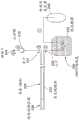
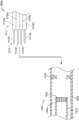
图5A是根据本发明的实施例的冷冻消融导管的透视图;5A is a perspective view of a cryoablation catheter according to an embodiment of the present invention;
图5B是沿图5A中的线5B-5B截取的横截面图;Figure 5B is a cross-sectional view taken along
图6是根据本发明的实施例的包括冷冻消融导管的冷冻消融系统的图示;6 is an illustration of a cryoablation system including a cryoablation catheter according to an embodiment of the present invention;
图7是图6所示的冷冻消融导管的远侧段的放大透视图;Figure 7 is an enlarged perspective view of the distal section of the cryoablation catheter shown in Figure 6;
图8是具有柔性远侧治疗段的冷冻消融导管的另一个实施例的透视图;8 is a perspective view of another embodiment of a cryoablation catheter with a flexible distal treatment segment;
图9A是沿着图9中的线9A-9A截取的图8中所示的导管的实施例的横截面图;9A is a cross-sectional view of the embodiment of the catheter shown in FIG. 8 taken along
图9B是图9A中所示的多层管中的一个的放大视图;Figure 9B is an enlarged view of one of the multilayer tubes shown in Figure 9A;
图9C是冷冻消融导管的另一个实施例的横截面图;9C is a cross-sectional view of another embodiment of a cryoablation catheter;
图10A是图8所示的导管的实施例的局部截面图;10A is a partial cross-sectional view of the embodiment of the catheter shown in FIG. 8;
图10B是管元件的近端和图8中所示的导管的实施例的中间段的远端的局部分解图;Figure 10B is a partial exploded view of the proximal end of the tube element and the distal end of the intermediate section of the embodiment of the catheter shown in Figure 8;
图11是具有柔性远侧治疗段的冷冻消融导管的另一个实施例的透视图;Figure 11 is a perspective view of another embodiment of a cryoablation catheter with a flexible distal treatment segment;
图12是图11所示的远侧段的一部分的放大视图;Figure 12 is an enlarged view of a portion of the distal segment shown in Figure 11;
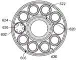
图13是沿着图12的线13-13截取的图12中所示的导管的横截面图;Figure 13 is a cross-sectional view of the catheter shown in Figure 12 taken along line 13-13 of Figure 12;
图14-图15图示了图11所示导管的远侧段从外鞘构件的顺序展开;Figures 14-15 illustrate the sequential deployment of the distal section of the catheter shown in Figure 11 from the outer sheath member;
图16是具有柔性远侧治疗段的冷冻消融导管的另一个实施例的透视图;Figure 16 is a perspective view of another embodiment of a cryoablation catheter with a flexible distal treatment segment;
图17是图16所示的导管的远侧段的放大视图;Figure 17 is an enlarged view of the distal section of the catheter shown in Figure 16;
图18是沿着图17的线17-17截取的图17中所示的导管的横截面图;Figure 18 is a cross-sectional view of the catheter shown in Figure 17 taken along line 17-17 of Figure 17;
图19A-图19D示出了根据本发明的实施例的导管的远侧段的展开;19A-19D illustrate deployment of a distal segment of a catheter according to an embodiment of the present invention;
图20A-图20B示出了减小图19D所示导管的预设环形的直径;Figures 20A-20B illustrate reducing the diameter of the preset annulus of the catheter shown in Figure 19D;
图21A-图21C示出了根据本发明的实施例的导管轴的铰接(articulation);21A-21C illustrate articulation of a catheter shaft according to an embodiment of the present invention;
图22A-图22B示出了导管的中间段的部件;22A-22B show components of the middle section of the catheter;
图23A示出了根据本发明的实施例的用于消融导管的手柄的透视图;23A shows a perspective view of a handle for an ablation catheter according to an embodiment of the present invention;
图23B示出了图23A所示手柄的局部透视图,其中外部被移除;Figure 23B shows a partial perspective view of the handle shown in Figure 23A with the exterior removed;
图24是具有内部通针的冷冻消融导管的另一个实施例的透视图;Figure 24 is a perspective view of another embodiment of a cryoablation catheter with an internal needle;
图25A-图25C是对应于图24中的24A-24A线的本发明不同实施例的横截面图;Figures 25A-25C are cross-sectional views of various embodiments of the invention corresponding to lines 24A-24A in Figure 24;
图26是图25A所示的多层冷冻剂递送/返回管的放大视图;Figure 26 is an enlarged view of the multilayer cryogen delivery/return tube shown in Figure 25A;
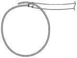
图27A是图24所描绘的冷冻消融导管的透视图,其中插入了内部通针;Fig. 27A is a perspective view of the cryoablation catheter depicted in Fig. 24 with the inner needle inserted;
图27B是图24所描绘的冷冻消融导管的透视图,其中插入了内部通针,消融轴/套管的柔性远侧消融部分转变成通针的弯曲构型;Fig. 27B is a perspective view of the cryoablation catheter depicted in Fig. 24 with the inner needle inserted and the flexible distal ablation portion of the ablation shaft/cannula converted to the curved configuration of the needle;
图28A-图28C是对应于图27A中的线27A-27A的本发明的各种实施例的横截面图;Figures 28A-28C are cross-sectional views of various embodiments of the invention corresponding to lines 27A-27A in Figure 27A;
图29描绘了通针的样本形状;Figure 29 depicts the sample shape of the needle;
图30描绘了根据本发明的实施例的沿其长度具有多处柔性部的通针;30 depicts a through needle having multiple flexures along its length in accordance with an embodiment of the present invention;
图31A描绘了根据本发明的实施例的改变通针的一部分的柔性的方法;31A depicts a method of changing the flexibility of a portion of a needle according to an embodiment of the present invention;
图31B描绘了根据本发明的实施例的图31A中的视图A;Figure 31B depicts view A in Figure 31A according to an embodiment of the present invention;
图32A描绘了根据本发明的实施例的改变通针的一部分的柔性的方法;32A depicts a method of changing the flexibility of a portion of a needle according to an embodiment of the present invention;
图32B描绘了根据本发明的实施例的改变通针的一部分的柔性的方法;32B depicts a method of changing the flexibility of a portion of a needle according to an embodiment of the present invention;
图32C描绘了根据本发明的实施例的改变通针的一部分的柔性的方法;32C depicts a method of changing the flexibility of a portion of a needle according to an embodiment of the present invention;
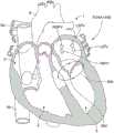
图33是根据本发明的实施例的各种损伤的位置以及心脏的图示;33 is an illustration of the location of various lesions and the heart according to an embodiment of the present invention;
图34是进入心脏的血管内导管的实施例的图示;Figure 34 is an illustration of an embodiment of an intravascular catheter into the heart;
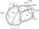
图35-图36是根据本发明的实施例将冷冻消融导管的远侧段抵靠左心房内的心内膜壁放置的过程的图示,该过程限定了左上肺静脉入口和左下肺静脉入口;35-36 are illustrations of the process of placing a distal segment of a cryoablation catheter against the endocardial wall within the left atrium, which defines the left superior pulmonary vein entrance and the left inferior pulmonary vein entrance, in accordance with embodiments of the present invention;
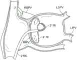
图37-图38是根据本发明的实施例将冷冻消融导管的远侧段抵靠左心房内的心内膜壁放置的过程的示意图,该过程限定了右上肺静脉入口和右下肺静脉入口。37-38 are schematic illustrations of the process of placing a distal segment of a cryoablation catheter against the endocardial wall within the left atrium, which defines the right upper and lower pulmonary vein inlets, according to embodiments of the present invention.
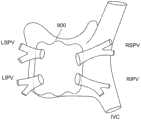
图39-图40图示了根据本发明的实施例的用于产生盒形损伤的方法,其中附图描绘了从患者背部观察的左心房;Figures 39-40 illustrate a method for producing a box-shaped lesion according to an embodiment of the present invention, wherein the figures depict the left atrium viewed from the back of a patient;
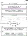
图41是示出了根据本发明的实施例在左心房中产生包围多个PV的盒形损伤的方法的流程图;41 is a flowchart illustrating a method of producing a box-shaped lesion enclosing a plurality of PVs in the left atrium according to an embodiment of the present invention;
图42是显示二尖瓣电活动的心脏的图示;Figure 42 is an illustration of a heart showing electrical activity of the mitral valve;
图43A描绘了根据本发明的实施例的中断二尖瓣电活动的损伤的形成;Figure 43A depicts the formation of a lesion that interrupts the electrical activity of the mitral valve according to an embodiment of the present invention;
图43B描绘了根据本发明的实施例的中断二尖瓣电活动的损伤的形成;43B depicts the formation of a lesion that interrupts the electrical activity of the mitral valve according to an embodiment of the present invention;
图44是示出了根据本发明的实施例在左心房中产生包围多个PV的盒形损伤和中断二尖瓣电活动的损伤的方法的流程图;和Figure 44 is a flowchart illustrating a method of producing a box-shaped lesion enclosing a plurality of PVs and a lesion that disrupts mitral valve electrical activity in the left atrium in accordance with an embodiment of the present invention; and
图45描绘了根据本发明的实施例的中断右心房中的电活动的损伤的形成。45 depicts the formation of a lesion that interrupts electrical activity in the right atrium, according to an embodiment of the present invention.
详细描述Detailed Description
应理解,由于对于描述的本发明的实施例可以进行各种改变或修改并且等同物可以被替换而不脱离本发明的实施例的精神和范围,因此本文所描述的本发明的实施例不限于本文所陈述的特定变型。在阅读本公开内容之后对本领域技术人员来说将明显的是,本文所描述和示出的各个实施例中的每个具有分立的部件和特征,这些部件和特征可在不脱离本发明的实施例的范围或精神的情况下与其它若干实施例中的任一个的特征容易地分离或组合。此外,可以进行许多修改以使特定的情况、材料、物质的组成、过程、过程行动或步骤适应于本发明实施例的目的、精神或范围。所有这样的修改旨在落入本文提出的权利要求的范围内。It should be understood that the embodiments of the invention described herein are not limited in that various changes or modifications may be made to the described embodiments of the invention and equivalents may be substituted without departing from the spirit and scope of the embodiments of the invention specific variations set forth herein. It will be apparent to those skilled in the art after reading this disclosure that each of the various embodiments described and illustrated herein have discrete components and features that can be practiced without departing from the invention The features of any of the other several embodiments can be easily separated or combined within the scope or spirit of the embodiments. In addition, many modifications may be made to adapt a particular situation, material, composition of matter, process, process act or step to the purpose, spirit or scope of the embodiments of the invention. All such modifications are intended to fall within the scope of the claims presented herein.
此外,尽管方法可以以特定次序在附图中描绘或在说明书中描述,但是这些方法不需要以所示的特定次序或按顺序来执行,并且不需要执行所有方法来获得期望的结果。未被描绘或描述的其他方法可以被结合到示例方法和过程中。例如,一个或更多个附加方法可在描述的任何方法之前、之后、同时或其间执行。此外,在其他实施方式中,这些方法可以被重新排列或重新排序。而且,以上所描述实施方式中的各种系统部件的分离不应被理解为在所有实施方式中要求该种分离,并且应被理解为通常可将所描述的部件和系统一起整合在单个产品中或者包装成多个产品。另外,其他实施方式在本公开的范围内。Furthermore, although methods may be depicted in the drawings or described in the specification in a particular order, these methods do not need to be performed in the particular order shown or sequential order, and need not be performed by all methods to obtain desirable results. Other methods not depicted or described may be incorporated into the example methods and processes. For example, one or more additional methods may be performed before, after, concurrently with, or between any of the methods described. Furthermore, in other embodiments, the methods may be rearranged or reordered. Furthermore, the separation of the various system components in the above-described embodiments should not be construed as requiring such separation in all embodiments, and should generally be understood to integrate the described components and systems together in a single product Or packaged into multiple products. Additionally, other implementations are within the scope of this disclosure.
除非另外特别说明或者在所用于的上下文中以其他方式被理解,否则条件措词,诸如“可(can)”、“可(could)”、“可能(might)”或“可以(may)”通常旨在表达某些实施例包括或不包括某些特征、元件和/或步骤。因此,此类条件措辞通常并非旨在以任意方式暗示一个或更多个实施例所需的特征、元件和/或步骤。Conditional words such as "can," "could," "might," or "may" unless specifically stated otherwise or otherwise understood in the context in which they are used It is generally intended to express that certain embodiments include or exclude certain features, elements and/or steps. Thus, such conditional expressions are generally not intended to imply in any way a required feature, element, and/or step of one or more embodiments.
除非另有特别说明,否则诸如短语“X、Y和Z中的至少一个”的连接语言在所用于的上下文中通常被理解为传达项目、术语等可以是X、Y或Z。因此,这种连接语言通常不意图暗示某些实施例需要X中的至少一个、Y中的至少一个和Z中的至少一个存在。Conjunctive language such as the phrase "at least one of X, Y, and Z" is generally understood in the context in which it is used to convey that the item, term, etc. can be X, Y, or Z unless specifically stated otherwise. Thus, this connection language is generally not intended to imply that certain embodiments require the presence of at least one of X, at least one of Y, and at least one of Z.
对单个项目的引用包括存在复数个相同项目的可能性。更具体地,如本文和所附的权利要求中使用的,单数形式“一个(a)”、“一个(an)”、“所述(said)”和“该(the)”包括复数指示物,除非上下文清楚地另外指明。还要注意,权利要求可被设计为排除了任何可选要素。该声明旨在充当用于这种排他性术语如“仅仅”“只”以及与权利要求要素的列举有关的类似术语的使用或者“否定”限制的使用的先行基础。Reference to a single item includes the possibility that there are multiple identical items. More specifically, as used herein and in the appended claims, the singular forms "a", "an", "said" and "the" include plural referents , unless the context clearly dictates otherwise. Also note that the claims may be designed to exclude any optional element. This statement is intended to serve as an antecedent basis for the use of such exclusive terms as "only," "only," and similar terms in connection with the recitation of claim elements, or the use of "negative" limitations.
将理解,当元件被提及为“连接”或“耦合”到另一元件时,它可以直接连接或耦合到另一元件,或者可以存在中间元件。相反,如果元件被提及为“直接连接”或“直接耦合”到另一个元件时,不存在中间元件。It will be understood that when an element is referred to as being "connected" or "coupled" to another element, it can be directly connected or coupled to the other element or intervening elements may be present. In contrast, if an element is referred to as being "directly connected" or "directly coupled" to another element, there are no intervening elements present.
还将理解的是,尽管术语第一、第二等在本文可用于描述各个元件,但这些元件不应被这些术语限制。这些术语只是用来将一个元件与另一个区分开。因此,第一元件可以被称为第二元件,而不脱离本发明的教导。It will also be understood that, although the terms first, second, etc. may be used herein to describe various elements, these elements should not be limited by these terms. These terms are only used to distinguish one element from another. Thus, a first element could be termed a second element without departing from the teachings of the present invention.
本文使用的程度语言,例如术语“大约”、“约”、“大致”和“基本上”,表示接近所述值、量或特性的值、量或特性,其仍然执行期望的功能或实现期望的结果。例如,术语“大约”、“约”、“大致”和“基本上”可以指小于或等于所述量的10%、小于或等于所述量的5%、小于或等于所述量的1%、小于或等于所述量的0.1%以及小于或等于所述量的0.01%的量。如果所述量是0(例如,无,没有),上述范围可以是特定范围,并且不在该值的特定百分比内。此外,数值范围包括界定范围的数字,并且本文提供的任何单个值可以作为包括本文提供的其他单个值的范围的端点。例如,诸如1、2、3、8、9和10的一组值也是1-10、1-8、3-9等的数字范围的公开。Language of degree, such as the terms "about," "approximately," "substantially," and "substantially," as used herein, means a value, quantity, or characteristic that approximates the stated value, quantity, or characteristic, which still performs the desired function or achieves the desired the result of. For example, the terms "about", "about", "approximately" and "substantially" can mean less than or equal to 10% of the stated amount, less than or equal to 5% of the stated amount, less than or equal to 1% of the stated amount , an amount less than or equal to 0.1% of said amount and less than or equal to 0.01% of said amount. If the amount is 0 (eg, none, none), the above range may be a specific range and not within a specific percentage of the value. Furthermore, numerical ranges include the numbers that define the range, and any single value provided herein can be taken as an endpoint of a range that includes other single values provided herein. For example, a set of values such as 1, 2, 3, 8, 9, and 10 are also disclosures of numerical ranges of 1-10, 1-8, 3-9, and the like.
已经结合附图描述了一些实施例。附图是按比例绘制的,但是这种比例不应该是限制性的,因为除了所示的尺寸和比例之外的尺寸和比例都是可以预期的,并且都在所公开的发明的范围内。距离、角度等仅仅是说明性的,不一定与所示设备的实际尺寸和布局有精确的关系。可以添加、移除和/或重新排列部件。此外,本文结合各种实施例公开的任何特定特征、方面、方法、性能、特性、质量、属性、元件等可用于本文阐述的所有其他实施例中。此外,将认识到,本文描述的任何方法可以使用适合于执行所述步骤的任何设备来实践。Some embodiments have been described in conjunction with the accompanying drawings. The drawings are drawn to scale, but such proportions should not be limiting as dimensions and proportions other than those shown are contemplated and are within the scope of the disclosed invention. Distances, angles, etc. are illustrative only and do not necessarily have a precise relationship to the actual size and layout of the device shown. Components can be added, removed, and/or rearranged. Furthermore, any specific features, aspects, methods, properties, characteristics, qualities, attributes, elements, etc. disclosed herein in connection with various embodiments may be used in all other embodiments set forth herein. Furthermore, it will be appreciated that any of the methods described herein can be practiced using any apparatus suitable for performing the steps described.
虽然已经详细描述了多个实施例及其变型,但是使用它们的其他修改和方法对于本领域技术人员来说是明显的。因此,应当理解,在不脱离本文独特的和创造性的公开或权利要求的范围的情况下,各种应用、修改、材料和替代可以是等效的。While a number of embodiments and variations thereof have been described in detail, other modifications and methods of using them will be apparent to those skilled in the art. Accordingly, it should be understood that various applications, modifications, materials and substitutions may be equivalent without departing from the scope of the unique and inventive disclosure or claims herein.
本文中提到的所有现有主题(例如出版物、专利、专利申请和硬件)通过引用以其整体并入本文,除了提到的现有主题可能与本发明的主题冲突以外(在这种情况下,以本文呈现的内容为准)。All prior subject matter mentioned herein (eg, publications, patents, patent applications, and hardware) is hereby incorporated by reference in its entirety, except that prior subject matter mentioned may conflict with the subject matter of the present invention (in which case below, subject to the content presented in this article).
本发明的实施例利用了使用冷冻剂的热力学过程,该冷冻剂提供冷却而不会遇到汽塞的现象。Embodiments of the present invention utilize a thermodynamic process using a cryogen that provides cooling without encountering the phenomenon of vapor locks.
冷冻剂相图和近临界点Refrigerant Phase Diagram and Near Critical Points
本申请使用相图来说明各种热力学过程。图1中示出了示例相图。该相图包括对应于压力P和温度T的轴,以及描绘了液体和气体共存的所有(P,T)点的轨迹的相线102。对于相线102左侧的(P,T)值,冷冻剂处于液态,其通常以较高的压力和较低的温度获得,而在相线102的右侧的(P,T)值界定冷冻剂处于气态的区域,其通常以较低的压力和较高的温度获得。相线102在被称为临界点104的单点中突然结束。在氮气N2的实例中,临界点处于Pc=3.396MPa和Tc=-147.15℃。This application uses phase diagrams to illustrate various thermodynamic processes. An example phase diagram is shown in FIG. 1 . The phase diagram includes axes corresponding to pressure P and temperature T, and a
当流体在压力逐渐增加期间具有存在的液相和气相两者时,系统沿着液-气相线102向上移动。在N2的实例中,在低压力下的液体比气相密集多达两百倍。压力的持续增加导致液体密度降低且气相密度增加,直到液体密度和气相密度只在临界点104处相等。液体和气体之间的区别在临界点104处消失。因此,当冷冻剂在本文定义为“近临界条件”的临界点周围的条件下流动时,避免了在液体冷冻剂之前的气体膨胀造成的向前流动的阻塞(“汽塞”)。在保持功能性流动的同时允许与临界点更大偏离的因素包括冷冻剂流的更大速度、流腔的更大直径以及基于热交换器或冷冻处理区的更低热载荷。The system moves upward along the liquid-
随着临界点从下面被接近,汽相密度增加且液相密度减小,直到正好在这两个相的密度完全相等的临界点处为止。在临界点以上,液相和汽相的区别消失,只留下单一的超临界相,在此流体同时具有液体和气体的性质(即,没有表面张力的稠密流体能够无摩擦流动)。As the critical point is approached from below, the vapor phase density increases and the liquid phase density decreases until exactly at the critical point where the densities of the two phases are exactly equal. Above the critical point, the distinction between liquid and vapor phases disappears, leaving only a single supercritical phase, where the fluid has both liquid and gas properties (ie, a dense fluid without surface tension can flow without friction).
范德瓦尔斯热力学状态方程是描述气体和液体的公认的方程:The van der Waals thermodynamic equation of state is a well-established equation describing gases and liquids:
(p+3/v2)(3v-1)=8t [方程1](p+3/v2 )(3v-1)=8t [Equation 1]
其中,p=P/Pc,v=V/Vc,以及t=T/Tc,并且Pc、Vc和Tc分别是临界压力、临界摩尔体积和临界温度。where p=P/Pc, v=V/Vc , andt =T/Tc , and Pc,Vc , andTc are critical pressure, critical molar volume, and critical temperature, respectively.
变量v、p和t通常分别被称为“对比摩尔体积”、“对比压力”和“对比温度”。因此,具有相同p、v和t值的任何两种物质都处于临近其临界点的相同流体热力学状态。方程1因此被称为体现了“对应状态的定律”。这在H.E.Stanley的Introduction to PhaseTransitions and Critical Phenomena(牛津大学科学出版物,1971年)中更充分地被描述,其整个公开内容出于所有目的通过引用以其整体并入本文。The variables v, p and t are commonly referred to as "comparative molar volume", "comparative pressure" and "comparative temperature", respectively. Therefore, any two substances with the same values of p, v and t are in the same fluid thermodynamic state near their critical point.
在本发明的实施例中,对比压力p固定在约为一的恒定值,并且因此在临近临界压力的固定的物理压力处,同时对比温度t随着施加至该设备的热载荷而变化。如果对比压力p是通过系统工程设置的恒量,那么对比摩尔体积v是对比温度t的精确函数。In an embodiment of the present invention, the contrast pressure p is fixed at a constant value of about one, and thus at a fixed physical pressure near the critical pressure, while the contrast temperature t varies with the thermal load applied to the device. If the contrast pressure p is a constant set by systems engineering, then the contrast molar volume v is an exact function of the contrast temperature t.
在本发明的其他实施例中,操作压力p可以被调整,使得在设备的温度t的变化过程中,v保持低于某一最大值,在该最大值处将导致汽塞状况。通常希望将p保持在最低值,在该最低值处这是可靠的,因为提高压力以实现p的更高值可能涉及更复杂和更昂贵的压缩机的使用,从而导致整个装置支撑系统的更昂贵的采购和维护以及更低的总体冷却效率。In other embodiments of the invention, the operating pressure p may be adjusted such that, during changes in the temperature t of the device, v remains below a certain maximum value at which a steam lock condition would result. It is generally desirable to keep p at a minimum value where this is reliable, as increasing the pressure to achieve higher values of p may involve the use of a more complex and expensive compressor, resulting in a more expensive overall plant support system Expensive purchase and maintenance and lower overall cooling efficiency.
对于v的条件以复杂的方式取决于体积流率dV/dt、液相和汽相的热容量、以及例如在液体和蒸汽两者中的导热系数、粘性等的输送性质。该精确关系不是在封闭形式中用代数方法得到,但是可以通过整合描述冷却设备内的质量和热量输送的模型方程来数值地确定。从概念上讲,当尖端(或用于输送冷冻剂和冷却组织的其它设备结构)的加热速率产生汽相时,就会发生汽塞。与蒸汽的流率乘以蒸汽的热容量除以蒸汽的摩尔体积成比例的该汽相的冷却能力不能够跟上对尖端的加热速率。当这发生时,为了吸收在冷冻剂流中通过液相转变为蒸汽的多余热量,越来越多的汽相形成。这形成了液体转变成汽相来填充尖端的逃逸条件,并且由于在流入尖端中的热量迅速增加其温度和压力时导致该汽相的大的压力,因此所有冷冻剂流有效地停止。该状况被称为“汽塞”。The conditions for v depend in a complex manner on the volume flow rate dV/dt, the heat capacity of the liquid and vapor phases, and transport properties such as thermal conductivity, viscosity, etc. in both liquid and vapor. This exact relationship is not derived algebraically in closed form, but can be determined numerically by integrating model equations describing mass and heat transport within the cooling device. Conceptually, a vapor lock occurs when the heating rate of the tip (or other device structure used to deliver cryogen and cool tissue) creates a vapor phase. The cooling capacity of this vapor phase, which is proportional to the flow rate of the steam multiplied by the heat capacity of the steam divided by the molar volume of the steam, cannot keep up with the heating rate to the tip. As this occurs, more and more vapor phase forms in order to absorb excess heat that is converted to vapor through the liquid phase in the refrigerant stream. This creates a runaway condition where the liquid transforms into the vapor phase to fill the tip, and all cryogen flow effectively stops due to the large pressure of the vapor phase as the heat flowing into the tip rapidly increases its temperature and pressure. This condition is referred to as a "steam lock".
根据本发明的一个实施例,液相和汽相的摩尔体积基本相同。冷却能力处于临界点,并且冷却系统避免了汽塞。另外,在稍微低于临界点的条件下,该装置也可以避免汽塞。According to one embodiment of the present invention, the molar volumes of the liquid and vapor phases are substantially the same. Cooling capacity is at a critical point, and the cooling system avoids steam locks. In addition, under conditions slightly below the critical point, the device can also avoid vapour locks.
冷冻消融系统cryoablation system
图2提供了在一个实施例中用于低温系统的结构布置的示意图,以及图3提供了说明当图2的系统被操作时由冷冻剂采取的热力学路径的相图。在两个图中有圆圈的数字标识符相对应,使得在图2中指示了达到沿着热力学路径确定的操作点的物理定位。以下的描述因此在描述冷却流的物理方面和热力学方面时有时会同时参考图2的结构图和图3的相图。2 provides a schematic diagram of a structural arrangement for a cryogenic system in one embodiment, and FIG. 3 provides a phase diagram illustrating the thermodynamic path taken by the cryogen when the system of FIG. 2 is operated. The circled numerical identifiers in both figures correspond so that in FIG. 2 the physical location to reach the operating point determined along the thermodynamic path is indicated. The following description therefore sometimes references both the structural diagram of FIG. 2 and the phase diagram of FIG. 3 when describing the physical and thermodynamic aspects of the cooling flow.
为了说明的目的,图2和图3都具体参考氮冷冻剂,但是这不意图是限制性的。本发明的实施例可以更一般地与任何合适的冷冻剂一起使用,例如氩、氖、氦、氢和氧。For illustrative purposes, Figures 2 and 3 both refer specifically to nitrogen cryogens, but this is not intended to be limiting. Embodiments of the present invention may be used more generally with any suitable cryogen, such as argon, neon, helium, hydrogen and oxygen.
在图3中,液-气相线用参考标号256标识,并且被冷冻剂遵循的热力学路径用参考标号258标识。In FIG. 3 , the liquid-gas phase line is identified with
低温发生器246用于以超过冷冻剂在其出口处的临界点压力Pc的压力供应冷冻剂,在图2和图3中参考标号①。虽然压力接近临界点压力Pc是有利的,但是冷却循环通常可以在相图中具有高于或稍微低于Pc的压力的任意点处开始。当初始压力接近临界点压力Pc时,本文描述的过程的冷却效率通常较大,使得在较高的压力处可以有为了实现所需的流动的增加的能量需求。因此,实施例有时可以包含各种较高的上部边界压力,但是通常在接近临界点处开始,例如在0.8和1.2倍的Pc之间,并且在一个实施例中,在约0.85倍的Pc处开始。The
如本文使用的,术语“近临界”指的是接近液体-蒸汽临界点。该术语的使用相当于“接近临界点”并且其是这样一种区域:其中液体-蒸汽系统充分接近于临界点、其中流体的动态粘度接近于正常气体的动态粘度并且远小于液体的动态粘度;另外,同时流体的密度接近于正常液态的密度。近临界流体的热容量甚至比其液相的热容量更大。气体状粘度、液体状密度和非常大的热容量的组合使得近临界流体是非常有效的冷却剂。对近临界点的提及指的是这样的区域,其中液体-蒸汽系统充分接近于临界点使得液相和汽相的波动大到足以形成在其背景值之上的热容量的极大增加。近临界温度是在临界点温度的±10%内的温度。近临界压力在临界点压力的0.8倍和1.2倍之间。As used herein, the term "near critical" refers to approaching the liquid-vapor critical point. The use of this term is equivalent to "close to the critical point" and it is a region in which the liquid-vapor system is sufficiently close to the critical point, in which the dynamic viscosity of the fluid is close to that of a normal gas and is much smaller than that of the liquid; In addition, at the same time the density of the fluid is close to that of a normal liquid state. The heat capacity of a near-critical fluid is even greater than that of its liquid phase. The combination of gas-like viscosity, liquid-like density, and very large heat capacity makes near-critical fluids very efficient coolants. Reference to near critical point refers to the region where the liquid-vapor system is sufficiently close to the critical point that the fluctuations in the liquid and vapor phases are large enough to create a large increase in heat capacity above their background values. A near critical temperature is a temperature within ±10% of the critical point temperature. The near-critical pressure is between 0.8 and 1.2 times the critical point pressure.
再次参考图2,冷冻剂流经管,该管的至少一部分被处于液态的冷冻剂的储器240环绕,降低了其温度而基本上不改变其压力。在图2中,储器显示为液N2,其中热交换器242设置在储器240内以从流动的冷冻剂提取热量。在储器240外部,热隔绝可以围绕管设置以防止当冷冻剂从冷冻剂发生器246流动时冷冻剂的不需要的变暖。在点②处,在通过与液体冷冻剂热接触而冷却后,冷冻剂具有较低的温度但是基本上在初始压力处。在某些情况下,如在图3中以轻微的压力下降的形式指示的,可能会有压力变化,条件是压力基本上不下降到临界点压力Pc之下,即不下降到确定的最小压力之下。在图3中所示的示例中,作为流经液体冷冻剂的结果,温度下降约是50℃。Referring again to Figure 2, the cryogen flows through a tube, at least a portion of which is surrounded by a
冷冻剂然后提供给用于在低温应用中使用的设备。在图2所示的示例性实施例中,冷冻剂提供至导管224的入口236,该导管224例如可以用在医用低温血管内应用中,但这不是必须的。The cryogen is then supplied to the equipment for use in cryogenic applications. In the exemplary embodiment shown in FIG. 2, the cryogen is provided to the
实际上,医疗设备的形式可以广泛变化,并且包括但不限于:仪器、器具、导管、设备、工具、装置和探针,而不管这种探针是短而刚性的,还是长而柔性的,也不管它是用于开放式、最小化、非侵入式、手动还是机器人手术。In practice, medical devices can vary widely in form and include, but are not limited to, instruments, appliances, catheters, devices, tools, devices, and probes, whether short and rigid or long and flexible, It doesn't matter if it's for open, minimal, non-invasive, manual or robotic surgery.
在实施例中,冷冻剂可以穿过导管的近侧部分、继续沿着导管的柔性中间段并且进入导管的远侧治疗段而引入。当冷冻剂在图2和图3中的标号②和③之间被输送通过导管,并穿过冷冻消融处理区域228时,可能存在冷冻剂在移动穿过与设备的交界部(例如,图2中的冷冻消融区域228)时其压力和/或温度的轻微的变化。这种变化通常可显示出温度的轻微上升以及压力的轻微下降。假定冷冻剂压力保持在确定的最小压力(及相关联的条件)之上,那么由于冷冻剂仅朝着临界点移回而不会遇到液-气相线256,因此温度的轻微上升不会显著影响性能,从而避免汽塞。In embodiments, the cryogen may be introduced through the proximal portion of the catheter, continuing along the flexible intermediate section of the catheter, and into the distal treatment section of the catheter. As the cryogen is delivered through the catheter between
在所述实施例中,可以使用包括止回阀216、流动阻抗和/流量控制器的组件来控制冷冻剂从冷冻剂发生器246通过导管224或其他设备的流动。导管224本身可以包括沿着其长度的真空绝缘体232(例如,覆盖物或套管)并且可以具有用于低温应用的冷的冷冻消融区域228。和工作冷冻剂的压力在探针尖端处显著改变的焦耳-汤姆逊(Joule-Thomson)探针不同,本发明的这些实施例提供贯穿整个装置在压力方面的相对小的变化。因此,在点④处,冷冻剂的温度已经大约上升到环境温度,但是压力保持升高。当冷冻剂通过导管输送时,通过保持压力高于或接近临界点压力Pc,可以避免汽塞。In the described embodiment, components including the check valve 216, flow impedance and/or flow controller may be used to control the flow of refrigerant from the
冷冻剂压力在点⑤处恢复到环境压力。冷冻剂然后可以在基本上环境条件下通过排放口204排出。The refrigerant pressure returns to ambient pressure at
以下共同转让的美国专利和美国专利申请中描述了冷冻消融系统、其部件和各种布置的示例:由Peter J.Littrup等人于2004年1月14日提交的美国专利申请第10/757,768号,其于2008年8月12日作为美国专利第7,410,484号发布,名称为“CRYOTHERAPY PROBE”;由Peter J.Littrup等人于2004年1月14日提交的美国专利申请第10/757,769号,其于2006年8月1日作为美国专利第7,083,612号发布,名称为“CRYOTHERAPY SYSTEM”;由PeterJ.Littrup等人于2004年9月27日提交的美国专利申请第10/952,531号,其于2007年9月25日作为美国专利第7,273,479号发布,名称为“METHODS AND SYSTEMS FOR CRYOGENICCOOLING”;由Peter Littrup等人于2006年6月6日提交的美国专利申请第11/447,356号,其于2009年3月24日作为美国专利第7,507,233号发布,名称为“CRYOTHERAPY SYSTEM”;由Peter Littrup等人于2007年8月28日提交的美国专利申请第11/846,226号,其于2011年4月12日作为美国专利第7,921,657号发布,名称为“METHODS AND SYSTEMS FOR CRYOGENICCOOLING”;由Peter Littrup等人于2008年1月23日提交的美国专利申请第12/018,403号,其于2013年11月26日作为美国专利第8,591,503号发布,名称为“CRYOTHERAPY PROBE”;由Peter Littrup等人于2011年3月11日提交的美国专利申请第13/046,274号,其于2013年3月5日作为美国专利第8,387,402号发布,名称为“METHODS AND SYSTEMS FOR CRYOGENICCOOLING”;由Peter Littrup等人于2013年11月22日提交的美国专利申请第14/087,947号,其正在审理中的名称为“CRYOTHERAPY PROBE”;由Alexei Babkin等人于2010年7月29日提交的美国专利申请第12/744,001号,其于2014年6月3日作为美国专利第8,740,891号发布,名称为“FLEXIBLE MULTI-TUBULAR CRYOPROBE”;由Alexei Babkin等人于2010年7月29日提交的美国专利申请第12/744,033号,其于2014年6月3日作为美国专利第8,740,892号发布,名称为“EXPANDABLE MULTI-TUBULAR CRYOPROBE”,;以及由Alexei Babkin等人于2014年9月22日提交的名称为“ENDOVASCULAR NEAR CRITICAL FLUID BASED CRYOABLATIONCATHETER AND RELATED METHODS”的美国专利申请第14/915,632号,上述每个美国专利/申请的内容出于所有目的,通过引用全部并入本文。Examples of cryoablation systems, components thereof, and various arrangements are described in the following commonly assigned US patent and US patent application: US Patent Application Serial No. 10/757,768, filed January 14, 2004 by Peter J. Littrup et al. , which was issued on August 12, 2008 as US Patent No. 7,410,484, entitled "CRYOTHERAPY PROBE"; US Patent Application No. 10/757,769, filed January 14, 2004 by Peter J. Littrup et al., which Issued August 1, 2006 as US Patent No. 7,083,612, entitled "CRYOTHERAPY SYSTEM"; US Patent Application Serial No. 10/952,531, filed September 27, 2004 by Peter J. Littrup et al., 2007 Issued September 25 as US Patent No. 7,273,479, entitled "METHODS AND SYSTEMS FOR CRYOGENICCOOLING"; US Patent Application Serial No. 11/447,356, filed June 6, 2006 by Peter Littrup et al., filed March 2009 Issued Aug. 24 as US Patent No. 7,507,233, entitled "CRYOTHERAPY SYSTEM"; US Patent Application No. 11/846,226, filed Aug. 28, 2007 by Peter Littrup et al. US Patent No. 7,921,657, entitled "METHODS AND SYSTEMS FOR CRYOGENICCOOLING"; US Patent Application No. 12/018,403, filed January 23, 2008 by Peter Littrup et al. Patent No. 8,591,503, titled "CRYOTHERAPY PROBE"; US Patent Application Serial No. 13/046,274, filed March 11, 2011 by Peter Littrup et al., filed March 5, 2013 as US Patent No. 8,387,402 Published under the title "METHODS AND SYSTEMS FOR CRYOGENICCOOLING"; US Patent Application Serial No. 14/087,947, filed Nov. 22, 2013 by Peter Littrup et al under the pending title "CRYOTHERAPY PROBE"; by Alexei Babkin US Patent Application Serial No. 12/744,001, filed Jul. 29, 2010 by et al., which was filed on Jun. 3, 2014 as US Patent No. 8,740,891 Published under the title "FLEXIBLE MULTI-TUBULAR CRYOPROBE"; US Patent Application Serial No. 12/744,033, filed Jul. 29, 2010 by Alexei Babkin et al., which issued Jun. 3, 2014 as U.S. Patent No. 8,740,892 , entitled "EXPANDABLE MULTI-TUBULAR CRYOPROBE", and U.S. Patent Application Serial No. 14/915,632, entitled "ENDOVASCULAR NEAR CRITICAL FLUID BASED CRYOABLATIONCATHETER AND RELATED METHODS," filed September 22, 2014 by Alexei Babkin et al., The contents of each of the above US patents/applications are incorporated herein by reference in their entirety for all purposes.
一种用于冷却目标组织的方法使用图4的流程图说明,其中冷冻剂遵循与图3所示的热力学路径相似的热力学路径。在块310处,冷冻剂以超过临界点压力的压力生成且邻近临界点温度。生成的冷冻剂的温度在块314处通过与具有较低温度的物质热交换而降低。在一些情况下,这可以通过使用与环境压力液态的冷冻剂的热交换方便地进行,尽管该热交换在不同的实施例中可以在其它条件下进行。例如,在一些实施例中可以使用不同的冷冻剂,例如当工作流体是氩时通过提供与液氮的热交换。此外,在其它可选择的实施例中,热交换可以使用在不同于环境压力的压力下的冷冻剂进行,例如通过提供在较低压力下的冷冻剂以形成较冷的环境。One method for cooling target tissue is illustrated using the flowchart of FIG. 4 , where the cryogen follows a thermodynamic path similar to that shown in FIG. 3 . At
另外的冷却冷冻剂在块318处提供给可以用于在块322处的冷却应用的低温应用设备。冷却应用可以根据目标是否使用冷却应用冻结而包括冷冻(chilling)和/或冻结(freezing)。作为冷冻剂应用的结果,冷冻剂的温度增加,并且在块326处加热的冷冻剂流向控制台。虽然可以有某种变化,但是冷冻剂压力通常贯穿块310-326保持高于临界点压力;在这些阶段处的冷冻剂的热力学性质中的主要变化是其温度。在块330处,加热的冷冻剂的压力然后允许降到环境压力,使得在块334处冷冻剂可以被排放出或者再循环。在其它实施例中,在块326处的剩余的加压冷冻剂也可以沿着路径返回至块310以再循环冷冻剂而不是在环境压力下排放冷冻剂。Additional cooling refrigerant is provided at
冷冻消融导管cryoablation catheter
本发明的冷冻消融装置的实施例可以具有多种配置。例如,本发明的一个实施例是如图5A所示的柔性导管400。导管400包括适于流体连接到流体源(未示出)的近侧设置的壳体或连接器410。Embodiments of cryoablation devices of the present invention may have a variety of configurations. For example, one embodiment of the present invention is a
多个流体传输管420被示出从连接器410延伸。这些管包括用于接收来自连接器的输入流的一组输入流体传输管422和用于从连接器410排出流的一组输出流体传输管424。A plurality of
在实施例中,流体传输管中的每一个由在从-200℃到环境温度的全范围温度中保持柔性的材料形成。在实施例中,流体传输管420由退火不锈钢或聚合物(如聚酰亚胺)形成。在这种配置中,材料可以在近临界温度时保持柔性。在实施例中,每个流体传输管具有在约0.1mm和1mm之间(优选地在约0.2mm和0.5mm之间)的范围中的内径。每个流体传输管可具有在约0.01mm和0.3mm之间(优选地在约0.02mm和0.1mm之间)的范围中的壁厚。In an embodiment, each of the fluid transfer tubes is formed of a material that remains flexible over the full range of temperatures from -200°C to ambient temperature. In an embodiment, the
端帽440定位在流体传输管的末端处以提供从输入流体传输管到输出流体传输管的流体传输。端帽440显示为具有防损伤尖端。端帽440可以是用于提供从输入流体传输管到输出流体传输管的流体传输的任何合适的元件。例如,端帽440可以界定用于流体连接管422、424的内腔室、空腔或通道。An
参考图5B,外鞘430被示为围绕管束420。外鞘用于将管保持在管状布置中,并保护结构免受外来物体和障碍物的穿透或破坏。Referring to FIG. 5B ,
温度传感器432显示在远侧段的表面上。温度传感器可以是热电偶,以感测对应于邻近组织的温度,并通过管束中的导线将信号发送回控制台进行处理。温度传感器可以被放置在沿着轴的其他地方或者一个或更多个流体传输管内,以确定流入和流出之间的温差。A
对于管的布置有许多种配置。在实施例中,流体传输管由圆形阵列形成,其中该一组输入流体传输管包括界定圆的中心区域的至少一个输入流体传输管422,并且其中该一组输出流体传输管424包括以圆形图案围绕该中心区域隔开的多个输出流体传输管。在图5B中所示的配置中,流体传输管422、424落入这类实施例内。There are many configurations for the arrangement of the tubes. In an embodiment, the fluid transfer tubes are formed from a circular array, wherein the set of input fluid transfer tubes includes at least one input
在操作期间,冷冻剂/冷冻流体在接近于-200℃的温度处从合适的冷冻剂源经过供应线到达导管,冷冻剂循环经过由暴露的流体传输管提供的多管状冻结区,并且返回至连接器。冷冻剂通过输入流体传输管422流入冻结区,并通过输出流体传输管424流出冻结区。During operation, the cryogen/refrigerated fluid is passed from a suitable cryogen source through the supply line to the conduit at a temperature close to -200°C, the cryogen circulates through the multi-tubular freezing zone provided by the exposed fluid transfer tube, and back to the Connector. The refrigerant flows into the freezing zone through the input
在实施例中,氮流在任意热载荷下都不在小直径管中形成气态气泡,以便不产生限制流动和冷却能力的汽塞。通过在至少能量应用的初始时段在近临界条件下操作,汽塞随着液相和气相之间的区别消失而消除。在近临界条件下(例如,对于氮气,在接近临界温度-147.15℃的温度下且在接近临界压力3.396MPa的压力下)进行初始操作之后,操作压力可以降低,如由Alexei Babkin于2015年10月21日提交的,名称为“PRESSURE MODULATEDCRYOABLATION SYSTEM AND RELATED METHODS”的共同转让的美国专利申请第14/919,681号中所公开和描述的,该专利申请的内容出于所有目的通过引用以其整体并入本文。In an embodiment, the nitrogen flow does not form gaseous bubbles in the small diameter tube under any thermal load so as not to create a steam plug that restricts flow and cooling capabilities. By operating under near-critical conditions for at least the initial period of energy application, the vapor lock is eliminated as the distinction between liquid and gas phases disappears. After initial operation under near-critical conditions (eg, for nitrogen, at a temperature near the critical temperature of -147.15°C and at a pressure near the critical pressure of 3.396 MPa), the operating pressure can be reduced, as described by Alexei Babkin on October 2015 As disclosed and described in commonly assigned U.S. Patent Application Serial No. 14/919,681, entitled "PRESSURE MODULATEDCRYOABLATION SYSTEM AND RELATED METHODS," filed on March 21, the contents of which are hereby incorporated by reference in their entirety for all purposes. into this article.
多管设计可以优选为单管设计,因为额外的管可以显著增加冷冻剂和组织之间的热交换面积。根据使用的管的数量,冷冻仪器可以增加超过具有类似大小直径的具有单个轴/管的以前设计几倍的接触面积。然而,本发明的实施例并不意图限于单管或多管设计,除非在所附权利要求中具体陈述。A multi-tube design may be preferred over a single-tube design, as the additional tubes can significantly increase the heat exchange area between the cryogen and tissue. Depending on the number of tubes used, the cryo-instrument can increase the contact area several times over previous designs with a single shaft/tube of similar size diameter. However, embodiments of the present invention are not intended to be limited to single-tube or multi-tube designs unless specifically recited in the appended claims.
冷冻消融控制台cryoablation console
图6示出了具有推车(cart)或控制台960的冷冻消融系统950和通过柔性长形管910可拆卸地连接至控制台的冷冻消融导管900。下文将结合图7更详细描述的冷冻消融导管900包含一个或更多个流体输送管以从组织中移除热量。FIG. 6 shows a
控制台960可以包括或容纳各种部件(未示出),例如发生器、控制器、箱(tank)、阀、泵等。为了方便用户操作,计算机970和显示器980在图6中示出为位于推车顶部。计算机可以包括控制器、定时器或者与外部控制器连通以驱动冷冻消融系统的部件(例如,泵、阀或发生器)。诸如鼠标972和键盘974的输入设备可以被提供以允许用户输入数据并且控制冷冻消融设备。
在实施例中,如本文描述的,计算机970配置为或编程为控制冷冻剂流率、压力和温度。目标值和实时测量结果可以发送到显示器980并且在显示器980上显示。In embodiments,
图7示出冷冻消融装置的远侧段900的放大视图。远侧段900类似于上述设计,除了治疗区域914包括柔性防护性覆盖物924。覆盖物用于在流体输送管之一破裂的情况下容纳冷冻剂的泄漏。虽然泄漏在流体递送输送管中的任一个中是不期望或不预期的,但是防护性覆盖物提供了冷冻剂将必须穿透以便在过程期间流出导管的额外的或多余的阻挡层。在实施例中,防护性覆盖物可以由金属形成。FIG. 7 shows an enlarged view of the
此外,导热液体可以设置在输送管和覆盖物的内表面之间的空间或间隙内,以提高设备在治疗期间的热冷却效率。在实施例中,导热液体是水。Additionally, a thermally conductive fluid can be placed in the space or gap between the delivery tube and the inner surface of the cover to increase the thermal cooling efficiency of the device during treatment. In an embodiment, the thermally conductive liquid is water.
覆盖物924被示出是管状的或圆柱形的并且终止在远侧尖端912处。如本文描述的,冷却区域914包含多个流体递送管和流体返回管以输送冷却流体经过治疗区域914,导致热量从目标组织被传输/移除。在实施例中,冷冻剂在邻近相图中的流体的临界点的物理条件下被输送经过管束。除其它以外,覆盖物有助于容纳冷却流体并且防止其在递送管中的一个中形成泄漏的情况下从导管逸出。Cover 924 is shown to be tubular or cylindrical and terminates at
尽管在图6-7中示出了覆盖物,但是除了在所附权利要求中所述的以外,本发明并不意图受到这样的限制。该装置可以设有或不设有防护性覆盖物,并用于冷却目标组织。Although a cover is shown in Figures 6-7, the invention is not intended to be so limited, except as set forth in the appended claims. The device may or may not be provided with a protective covering and is used to cool the target tissue.
管中管tube in tube
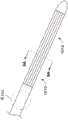
图8示出根据本发明的另一个实施例的冷冻消融导管1010的局部视图,该冷冻消融导管1010具有保护装置,该保护装置在冷却流体/冷冻剂从上面描述的冷冻剂递送管逸出的情况下减轻泄漏。特别是,导管1010包括多个柔性多层冷冻能量传输管或者柔性多层冷冻能量传输管的束1012,其中的每一个包括以同轴布置的两个管,也就是管中管。Figure 8 shows a partial view of a
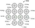
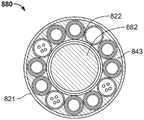
图9A示出沿图8的线9A-9A截取的横截面图。多层管的束1012被示出有以平行布置组装的流体递送管1014和流体返回管1015。管束1012被示出具有12根管/线,包括四(4)根流体返回管1015a-1015d和八(8)根流体递送管1014a-1014h。流体递送管1014a-1014h形成围绕流体返回管1015a-1015d的周界。这种布置确保了较冷的递送流体/冷冻剂邻近待消融/冻结的组织,并且较热的返回流体/冷冻剂与待消融/冻结的组织隔离。FIG. 9A shows a cross-sectional view taken along
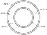
图9B示出了图9A的流体递送管1014d的放大横截面图。第一管或内管1013被示出为被第二管或者外管1018同轴地环绕。如本文描述的,在内管1013的外表面和外管1018的内表面之间的空间或间隙1020能够被导热介质1021填充。在实施例中,间隙1020具有环形形状。所有的流体递送管1014以及流体返回管1015可以在管结构内具有类似的管。Figure 9B shows an enlarged cross-sectional view of the
在使用过程中,如果冷却流体1016泄漏或内管1013破裂,冷却流体1016被包含在内管1013和外管1018之间的间隙1020内。由于任何泄漏的流体/冷冻剂1016被限制在导管内并且被阻止进入患者体内,所以这个管中管特征为该设备增加了额外的安全元件。在一些实施例中,可以结合压力传感器/设备或压力计来监测间隙1020中导热介质1021的压力。因此,如果流体/冷冻剂1016冲破了内管1013并泄漏到间隙1020中,则间隙1020中的压力将增加,因此传导介质1021的压力也将增加。如果压力变化超过阈值极限,可将系统编程为停止消融,从而防止对患者的潜在伤害和/或通知用户/医生该压力变化。During use, if the cooling fluid 1016 leaks or the
内管1013可以由如本文描述的与用于输送冷却流体的其它柔性管有关的材料制备或制作。The
如本文所公开的,外管1018的材料也应该是柔性的,以使远侧治疗段能够弹性偏转,从而允许远侧治疗段改变其形状。在一些实施例中,外管是不可充气的、不可扩张的,也不可膨胀的,使得其尺寸和形状基本上不受其中包含的导热介质1021存在的影响。用于外管1018的非限制的示例性材料包括聚合物和金属或者合金。外管1018的材料的示例是镍钛诺或聚酰亚胺。As disclosed herein, the material of the
形成管状束1012的管的数量可能差异很大。在一些实施例中,管状束1012包括5-15根管,更优选地包括8-12根管,其包括流体递送管1014和流体返回管1015。The number of tubes forming the
管束1012的横截面轮廓也可以变化。虽然图9A示出大体上圆形的轮廓,但是,在实施例中,该轮廓可以是包括上面描述的布置中的一些的矩形、正方形、十字形或t形,环形或圆周形,或者另一种形状轮廓。管也可以编结(braided)、编织、扭缠或以其他方式缠绕在一起,如由Alexei Babkin等人于2014年9月22日提交的名称为“ENDOVASCULAR NEARCRITICAL FLUID BASED CRYOABLATION CATHETER AND RELATED METHODS”的共同转让的美国专利申请第14/915,632号的图9、图14和图16所描绘的,其全部内容出于所有目的通过引用并入本文。The cross-sectional profile of the
冻结段或管状束的直径可以变化。在实施例中,束的直径范围是约1-3mm,并且优选约2mm。The diameter of the frozen segment or tubular bundle can vary. In an embodiment, the diameter of the beam is in the range of about 1-3 mm, and preferably about 2 mm.
图9C示出了具有另一管状布置1017的冷冻消融导管的横截面。八(8)个管状元件(1019a-1019d和1023a-1023d)围绕芯元件1025周向间隔或分布。优选地,如所示出,流体递送元件/管(1019a-1019d)和流体返回元件/管(1023a-1023d)沿着导管的圆周交替。9C shows a cross-section of a cryoablation catheter with another
如参照图9B所述,每个内部管状元件(例如,1019a)包括同轴地围绕内部管状元件的外部管状元件(例如,1027a),从而产生可填充导热介质/流体的空间或间隙。As described with reference to Figure 9B, each inner tubular element (eg, 1019a) includes an outer tubular element (eg, 1027a) coaxially surrounding the inner tubular element, creating a space or gap that can be filled with a thermally conductive medium/fluid.
操纵元件、传感器和其它功能元件可以结合到导管中。在实施例中,将操纵元件结合到机械芯中,例如图9C所示的机械芯1025。Steering elements, sensors and other functional elements can be incorporated into the catheter. In an embodiment, the manipulation element is incorporated into a mechanical core, such as
图10A示出图8中细节10A处的导管的放大剖视图,说明了管束1012流体地连接至导管1010的中间段的端部部分1040。FIG. 10A shows an enlarged cross-sectional view of the conduit at detail 10A of FIG. 8 , illustrating that the
图10B示出导管的中间段1040和管束1012的近侧段的分解图。具有延伸超出流体递送线1014的外部管状元件/覆盖物1018a-1018d的内部管状元件1013a-1013d的管束1012可以插入导管的中间段1040中。10B shows an exploded view of the
参考图10A-10B,流体递送线1014被示为被捆在一起并且插入/联接至主线1032。粘合塞1042或密封件、垫圈或止动件等可以被应用以帮助并确保在管构件之间的流体密封。冷却能力流体(CPF)从流体递送主线1032输送至流体返回线1014。Referring to FIGS. 10A-10B , the
从内部管状元件1013a-1013d的近端偏移的外部管状元件/覆盖物1018a-1018d的近端被示出插入导管的中间段1040中,使得腔1050内的导热流体(TCF)可以填充多层冷冻能量管状元件中的每一个的间隙1020(图9B)。粘合塞1044(焊接或粘结)可以被应用以促进流体密封的和坚固的连接。如对于本领域的技术人员是已知的,压入配合、加热和其它制造技术可以应用以联接部件。The proximal ends of the outer tubular elements/covers 1018a-1018d, offset from the proximal ends of the inner
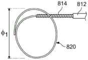
图11示出了另一种冷冻消融导管500,其包括远侧治疗段510、手柄520和脐带绳(umbilicalcord)530。脐带绳530的近端终止于连接器540,连接器540插入控制台550上的插座端口560。FIG. 11 shows another
一个或更多个辅助连接器线570被示为从手柄520向近端延伸。管状线570可用于提供各种功能,包括但不限于(a)冲洗;(b)真空;(c)如上所述的导热液体;和/或(d)温度和压力传感器导体。One or more
导管500还显示为具有从手柄520向近端延伸的电连接器580。电连接器580可以耦合到用于分析在远侧治疗段510中检测到的电信息的EP记录系统。用于分析电活动的系统的示例包括但不限于由美国通用电气医疗公司(GE Healthcare)制造的GE HealthcareCardioLab II EP Recording System和由波士顿科学公司(Boston Scientific Inc.)(马萨诸塞州马尔堡)制造的LabSystem PRO EP Recording System。所记录的电活动也可用于评估或验证与目标组织的持续接触,如由Alexei Babkin等人于2016年9月15日提交的名称为“TISSUE CONTACT VERIFICATION SYSTEM”的共同转让的国际专利申请第PCT/US16/51954号中所述,其全部内容出于所有目的通过引用并入本文。
图12示出了导管500的远侧段510的一部分的放大视图。环形电极602、604围绕轴606周向设置。尽管示出了两个电极,但是在轴上可以存在更多或更少的电极用于感测电活动。在实施例中,在轴上提供多达12个电极。在一个实施例中,8个电极沿着轴606轴向间隔开。FIG. 12 shows an enlarged view of a portion of the
图13是沿着线13-13截取的图12中所示的导管的横截面。导管轴显示为具有沿中心轴线延伸的机械芯620,以及平行延伸并围绕机械芯周向设置的多个能量递送管构造630。Figure 13 is a cross-section of the catheter shown in Figure 12 taken along line 13-13. The catheter shaft is shown with a
每个管构造630示出为具有结合图8-9如上所述的双层和设置在其间的导热液体层。Each
管状线624示出为用于容纳本文描述的用于各种传感器的导线626。
机械芯620可被构造成向导管远侧治疗段提供预设形状。参照图13,机械芯包括具有预设形状的金属管状构件622。预设形状匹配目标解剖结构,以与目标解剖结构连续接触。预设管状元件622的示例性材料是镍钛诺。图13还显示了同心围绕镍钛诺管的外部层或覆盖物。外部覆盖物可以是柔性聚合物,例如PET。内部PET层620和外部轴层606共同形成流体密封的环形腔室,以容纳多个管状构造630。The
参考图14-15,导管608显示为从外鞘642展开。最初,导管远侧段606设置在外鞘642的腔内,并且被禁止呈现其预设形状。远侧段606和外鞘642相对于彼此轴向移动。例如,导管可以从鞘中弹出。一旦导管不受约束,它就呈现如图15所示的预设形状。Referring to FIGS. 14-15 ,
机械芯组件偏置导管远侧段608的形状,迫使能量递送元件成为曲线形状。在实施例中,导管形状适于在右心房中产生用于治疗心房扑动的损伤。例如,图15所示的形状是单环或椭圆形状,其具有匹配用于治疗心房扑动的右心房中的组织的目标区的曲率。在2014年4月17日提交的共同转让的美国专利申请第61/981,110号、现在是2015年10月21日提交的名称为“ENDOVASCULAR NEAR CRITICAL FLUID BASED CRYOABLATION CATHETER HAVINGPLURALITY OF PREFORMED TREATMENT SHAPES”的国际专利申请第PCT/US2015/024778号中描述了用于治疗心房扑动的附加装置和方法,这两个申请的内容出于所有目的通过引用以其整体并入本文。The mechanical core assembly biases the shape of the catheter
图16示出了另一种冷冻消融导管700,其包括远侧治疗段710、手柄720和终止于连接器740的脐带绳730。类似于上面结合图11描述的系统,连接器740可以插入控制台上的插座端口。FIG. 16 shows another
额外的线742,744显示为从手柄向近端延伸。线742,744在手术过程中为远侧治疗段710提供各种功能。示例功能包括但不限于温度、EP记录、压力、流体冲洗、源液体等。
图17是展开后导管远侧段的放大视图。治疗段显示为具有大致环形或椭圆形的形状714。中间段716显示为提供了从中心轴线718的弯曲或铰接。这种功能有助于将治疗段定位成与组织持续直接接触。在实施例中,该形状被配置成在左心房中产生完全PVI。Figure 17 is an enlarged view of the distal segment of the catheter after deployment. The treatment segment is shown as having a generally annular or
图18是远侧治疗段的一部分的放大横截面图。导管轴显示为具有沿中心轴线延伸的机械芯750,以及平行延伸并周向围绕机械芯的多个能量递送管构造752。一个或更多个备用管状元件754,758可以与能量递送元件一起结合到周边空间中。管状元件754容纳多个电导体以传送来自远侧治疗段上存在的传感器或环形电极756的电活动。管状元件758可为导管提供真空或液体,用于本文所述的各种功能。Figure 18 is an enlarged cross-sectional view of a portion of the distal treatment segment. The catheter shaft is shown with a
机械芯750显示为轴向延伸穿过治疗段,并包括多个构件760,762,这些构件延伸穿过远侧治疗段,以将远侧段偏置成预设形状,例如图17所示的环形。具体而言,在实施例中,机械芯可以包括诸如镍钛诺丝的偏置形状元件760,以及连接到治疗段的远侧尖端以调节预设形状的曲率的轴向可移动控制构件762。如果需要,芯可以包括额外的腔766、768。该机械芯用于将远侧治疗段成形为第一预设环形,并且可以由控制构件进一步调节以与目标组织表面连续接触。
图19A-19D示出了消融导管810从具有轻微弯曲的第一弓形形状到具有完整环形或圆形形状820的第二配置的顺序展开。一旦导管治疗段不受外鞘812的约束,就呈现该形状。19A-19D illustrate the sequential deployment of
图20A-20B示出了图19D的导管800的放大视图,除了该环已经通过减小其直径ф1进行了调节。如本文所述,拉动延伸穿过远侧治疗段的轴的控制构件,以将预设环的直径ф1减小至如图20A所示的直径ф2。图20B示出了调节到比图20A所示直径更小的直径ф3的环。Figures 20A-20B show enlarged views of the
环的直径ф可以变化。在实施例中,环的直径被控制在2cm至5cm的范围内,并且在实施例中,优选为大约2-3cm。The diameter ф of the ring can vary. In an embodiment, the diameter of the ring is controlled to be in the range of 2 cm to 5 cm, and in an embodiment, preferably about 2-3 cm.
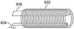
图21A-21C示出了导管的中间段814的顺序铰接。中间段814显示为具有外部支撑或加强结构816。在实施例中,支撑层816是弹簧或线圈。21A-21C illustrate the sequential articulation of the
图21A示出了导管中间段814基本上是直的或者与轴轴线对齐。Figure 21A shows that the catheter
图21B示出了导管中间段具有与轴轴线形成角度θ1的轻微铰接。Figure 21B shows that the middle section of the catheter hasa slight articulation forming an angle Θ1 with the axis of the shaft.
图21C示出了导管中间段具有与轴轴线的进一步铰接θ2。如下所述,医生可以改变和调整铰接的角度。在实施例中,铰接的角度与中心轴轴线成高达120度,更优选地达到大约90度。Figure 21C shows that the intermediate section of the catheter has further articulation [theta]2 with the shaft axis. As described below, the doctor can change and adjust the angle of the articulation. In an embodiment, the angle of articulation is up to 120 degrees from the central shaft axis, more preferably up to about 90 degrees.
图22A-22B示出了用于铰接中间段的部件/结构的示例。这些部件包括线圈832、第二拉线834和脊部836。拉线834被固定到中间段的远侧位置。拉动拉线会导致线圈832偏转或铰接。脊部836显示为与拉线在直径上相对。脊部用于在拉线缩回时偏置导管弯曲的方向,并且用于在拉线被释放时使导管返回其伸直定位。特别地,当拉线缩回时,导管沿着包括拉线、中心线圈轴线和脊部的平面向拉线弯曲。Figures 22A-22B illustrate examples of components/structures for articulating intermediate segments. These components include
各种铰接部件/结构可以由多种材料制成。示例性材料包括但不限于镍钛诺、不锈钢或具有本文所述功能的其他材料。此外,部件可以由金属丝、管状元件或库存材料片(sheets of stock material)制成。在一个实施例中,线圈和弹簧由一片金属合金整体形成。期望的形状可以被机械加工或激光切割以产生脊部和肋部元件,允许有偏置的铰接。还参见Kovalcheck等人于2003年5月30日提交的,名称为“Cryogenic Catheter withDeflectable Tip”的美国专利公开号2003/0195605,以获得描述导管的进一步细节,该导管包括用于控制偏转的弹簧、拉线和脊部。The various hinge components/structures can be made from a variety of materials. Exemplary materials include, but are not limited to, Nitinol, stainless steel, or other materials that have the functions described herein. Furthermore, the components may be made of wire, tubular elements or sheets of stock material. In one embodiment, the coil and spring are integrally formed from a single piece of metal alloy. The desired shape can be machined or laser cut to create ridge and rib elements, allowing for an offset hinge. See also US Patent Publication No. 2003/0195605, "Cryogenic Catheter with Deflectable Tip," filed May 30, 2003 by Kovalcheck et al. for further details describing a catheter including a spring for controlling deflection, Pull cords and ridges.
图23A示出了消融导管的手柄852的透视图。柔性导管轴854从手柄的远侧段856延伸。脐带绳858和各种其他功能线和连接器859显示为从手柄的近侧段860向近端延伸。Figure 23A shows a perspective view of the
手柄852被显示为具有人体工程学设计,包括光滑的平缓弯曲的中间段862,其允许用户方便地握住手柄。The
手柄显示为包括旋钮864,该旋钮864可以相对于手柄主体旋转,以控制如上所述的展开的环的直径。轴向可移动的毂866显示为靠近旋钮。毂866向前或向后的移动用于调节或铰接如上所述的展开的轴。此外,手柄可以作为整体旋转,以在一个方向或另一个方向上操纵导管。总的来说,手柄提供了一种方便且半自动的装置来转动、铰接和控制展开结构的直径或尺寸。The handle is shown to include a
图23B示出了图23A所示手柄的局部透视图,为清楚起见,其外部被移除。示出了一段外螺纹或齿872。齿872与旋钮864中的凹槽或螺纹配合。这些齿链接到上述第一控制构件,用于改变环的形状或直径。当旋钮旋转时,拉线同时移动。Figure 23B shows a partial perspective view of the handle shown in Figure 23A with the exterior removed for clarity. A length of external thread or
滑块874也显示在手柄中。滑块874联接到毂866,使得毂的移动导致滑块移动。如上所述,滑块还链接到第二控制构件,用于铰接导管轴。当外部毂被医生移动时,第二控制构件铰接轴。
尽管手柄显示为具有旋钮、毂和滑块,但是本发明并不局限于此。本发明可以包括用于实现上述功能的其他杠杆、齿轮、按钮和装置。Although the handle is shown with a knob, hub and slider, the invention is not so limited. The present invention may include other levers, gears, buttons and devices for accomplishing the functions described above.
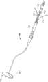
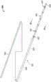
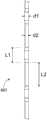
图24描绘的是根据本发明的另一个实施例的消融导管880。在该实施例中,消融导管880包括两个主要部件:(a)消融轴/套管881,用于将消融能量递送到人体内感兴趣的部位;以及(b)通针882,其能够插入到消融轴/套管881内的内部空腔中。如下面将更详细讨论的,消融轴/套管881的至少一部分由柔性材料制成,使得消融轴/套管881的这一部分可以呈现插入其中的并且由形状记忆合金构成的通针882的形状。尽管本文将消融导管880描述为用作通过用任何合适的冷冻剂(例如,但不限于,氮、氩、氖、氦、氢和氧)冻结组织来产生损伤的冷冻消融导管,但是在其他实施例中,消融导管可以与其他消融能量一起使用,例如,射频、微波、激光和高频超声(HIFU)。Figure 24 depicts an
如图24所描绘的,消融轴/套管881包括手柄部分(未示出,并且可以根据本文公开的任何手柄实施例构造)、第一轴部分883、柔性轴部分884、柔性远侧消融部分885和远侧消融尖端886。在一些实施例中,消融导管880还可包括柔性远侧消融部分885上的多个电极887,其可用于检测目标组织中的电活动,以便评估或验证柔性远侧消融部分885与目标组织的连续接触,如由Alexei Babkin等人于2016年9月15日提交的名称为“TISSUE CONTACTVERIFICATION SYSTEM”的共同转让的国际专利申请第PCT/US16/51954号中所述,其全部内容出于所有目的通过引用并入本文。在一些实施例中,电极887可以包括在远侧消融尖端886上。在一些实施例中,第一轴部分883可以是柔性的、半柔性的、半刚性的或刚性的。在一些实施例中,第一轴部分883的柔性小于柔性轴部分884,然而,第一轴部分883仍然是柔性的,使得其可以通过身体的静脉系统递送到目标组织。As depicted in Figure 24, ablation shaft/
在一些实施例中,消融轴/套管881可以包括手柄部分、柔性轴部分884、柔性远侧消融部分885和远侧消融尖端886。也就是说,消融轴/套管881可以沿着其整个长度是柔性的。In some embodiments, ablation shaft/
图25A描绘了沿图24中的线24A-24A截取的消融导管881的横截面图,其中通针882没有插入消融轴/套管881中。从横截面图中可以看出,消融轴/套管881包括用于将冷冻剂输送到柔性远侧消融部分885的多个多层冷冻剂递送管/腔888,以及用于将冷冻剂输送离开柔性远侧消融部分885的多个多层冷冻剂返回管/腔889。还示出了多个服务管/腔891,其可以包括导管控制线、电极线892或任何其他可能需要的元件。多个多层冷冻剂递送管/腔888、多个多层冷冻剂返回管/腔889和多个服务管/腔891围绕中空管/腔890布置成圆形阵列,该中空管/腔890适于在其中接收通针882。中空管/腔890沿着消融轴/套管881的长度从手柄延伸到至少柔性远侧消融部分885。25A depicts a cross-sectional view of
虽然图25A描绘了四(4)个多层冷冻剂递送管888、四(4)个多层冷冻剂返回管889和四(4)个服务管/腔891,但是本发明的实施例并不意图被如此限制,并且可以包括任意数量的多层冷冻剂递送管888、多层冷冻剂返回管889和服务管/腔891,这取决于导管的期望消融能力或导管将用于治疗的条件。此外,尽管图25A描绘了多层冷冻剂递送管888、多层冷冻剂返回管889和服务管/腔891的特定配置,特别是成对的多层冷冻剂递送管888和多层冷冻剂返回管889彼此相邻定位并且用服务管/腔891隔开,但是本发明的实施例并不意图被如此限制,并且可以包括用于多层冷冻剂递送管888、多层冷冻剂返回管889和服务通道/管891的任何数量的不同配置。Although Figure 25A depicts four (4) multilayer
空气间隙消除Air gap elimination
在一些实施例中,限定在外鞘821的内表面823和中空管/腔890的外表面822之间的环形空间813(见图25A)填充有导热液体(未示出),消除了热元件888、889和外鞘821之间的空气间隙/气泡。外鞘和致冷剂输送管和返回管/热元件888、889之间的空气间隙是不希望的,因为这种间隙降低了从热元件到目标组织的热传导。In some embodiments, the annular space 813 (see Figure 25A) defined between the inner surface 823 of the
合适的导热液体的示例是水。导热液体可以通过工作线(例如分别参照图11和图16描述的线570和742)输送到空间813。用导热水冲洗该空间,直到所有空气从该空间813中被去除。An example of a suitable thermally conductive liquid is water. The thermally conductive liquid may be delivered to space 813 by working lines such as
此外,尽管水被描述为用于冲洗空间813的合适的导热介质,如本文所述,但是本发明的实施例包括使用其他导热材料来消除空气间隙并增加导管的消融部分内的导热性能。Additionally, although water is described as a suitable thermally conductive medium for flushing space 813, as described herein, embodiments of the present invention include the use of other thermally conductive materials to eliminate air gaps and increase thermal conductivity within the ablation portion of the catheter.
参考图25B,示出了导管881的另一实施例的横截面。具体而言,与图25A所示的横截面不同,图25B所示的空间813填充有固体导热材料或衬套833,该材料或衬套833包括基础材料和具有高导热性的填料。用于导热衬套833的示例性基础材料包括但不限于适于传导热能的热塑性弹性体(TPE)或热塑性聚氨酯(TPU)。示例性填充材料包括但不限于铝、铜、银和金。Referring to Figure 25B, a cross-section of another embodiment of
在一些实施例中,填料可以是具有良好导热性的陶瓷材料,并且陶瓷材料优选是电绝缘的,以便隔离如本文所讨论的导管消融部分上包括的任何电极。示例性陶瓷填充材料包括但不限于BN(氮化硼)、AlN(氮化铝)、Si3N4(氮化硅)、SiC(碳化硅)、Al2O3(氧化铝)和ZnO(氧化锌)In some embodiments, the filler may be a ceramic material with good thermal conductivity, and the ceramic material is preferably electrically insulating in order to isolate any electrodes included on the catheter ablation portion as discussed herein. Exemplary ceramic filler materials include, but are not limited to, BN (boron nitride), AlN (aluminum nitride), Si3N4 (silicon nitride), SiC (silicon carbide), Al2O3 (aluminum oxide), and ZnO (zinc oxide)
如本领域技术人员容易理解的,任何具有高导热性的材料都可以用作填充材料。As readily understood by those skilled in the art, any material with high thermal conductivity can be used as the filler material.
TPE或TPU(基础材料)装填有导热试剂或填料,以增加基础材料的导热性。TPE的一个示例是聚醚嵌段酰胺(PEBA),这也众所周知是由Arkema(法国)制造的,商标名为

在特定实施例中,材料是装填有按重量计约10%-70%的氧化铝(Al2O3)的PEBA,并且在特别优选的实施例中,材料是装填有按重量计约65-75%的Al2O3的
通过将基础材料与填料混合成小球状材料,然后将所装填的材料挤压进所需管道中(适合于衬有本文所述的热元件888、889),可以用导热填料装填基础材料(例如,TPE或TPU)。The base material can be loaded with thermally conductive fillers (eg , TPE or TPU).
在实施例中,基础材料被装填成使得衬套833的热导率(K)比未用导热填料改性的基础材料大至少三至五倍,更优选大至少五倍。在实施例中,衬套833的热导率(K)在23℃下至少为1W/m-K,并且在从0.5W/m-K到3W/m-K的范围中。In an embodiment, the base material is packed such that the thermal conductivity (K) of the
导热衬套833可以以各种方式结合到导管中或以其他方式组装到导管中。在一些实施例中,衬套833在热能元件888、889和服务管891上热熔合。在热熔合步骤期间,衬套熔化并在热元件888、889和服务管891周围流动,直到热元件888、889和服务管891之间的空气间隙被完全填充和消除。在一些实施例中,外鞘随后被施加在热元件和衬套上,没有留下间隙。在一些实施例中,当传导性衬套833在热能元件888、889上热熔合时,外鞘不是必需的。在这些实施例中,衬套充当鞘。增加鞘可能只会增加设备或导管的刚度。此外,如果鞘不是由传导材料制成,则鞘可以充当热障(thermal barrier)。The thermally
围绕热元件888、889的导热衬套833的存在具有许多额外的好处,包括简化医疗程序和节省时间,因为医生不再需要用液体冲洗导管空间813来消除空气间隙。The presence of thermally
此外,导热衬套833使得导管的消融部分抗扭结。在外鞘821和热元件888、889之间没有导热衬套833的情况下,热元件不被支撑,除非热元件接触外鞘821(这通常发生在热元件的顶点)。另一方面,当空间813填充有本文所述的导热衬套833时,衬套的存在和性质机械地支撑热元件888、889和服务管891,并提供更大的抗扭结性。Additionally, the thermally
参考图25C,示出了导管881的另一实施例的横截面。特别地,与图25B所示的横截面不同,图25C中的导管881包括仅设置在热元件888、889和服务管892的外侧/周界上的导热衬套843。因此,在工作腔890和内部热元件888、889以及服务管892之间存在充气空间853。这个空间充当热障或绝缘体,因为空气具有低的导热率。然而,绝热空间853不是不利的,因为不希望将热能传导到中空管890。此外,使空间853开放/没有传导性衬套833允许热元件888、889更自由地移动。因此,热元件888、889没有结合/连接到中空管/腔890。这极大地增加了消融导管的柔性,并允许人们获得更小的弯曲半径和更复杂的形状。Referring to Figure 25C, a cross-section of another embodiment of
此外,本文所述的热塑性衬套可适于将导管的各种部件粘结在一起,并承受操作期间的温度变化。通过用某些低线性热膨胀系数(LCTE)试剂如石英装填衬套,衬套可以适于具有相对低的LCTE。在实施例中,PEBAX装填有按重量计为约60%的石英。增强型衬套可以是管的形式,其可用于将导管的各种部件热熔合/粘结在一起。优选地,线性热膨胀系数降低到0.5/K或更低。待联接的部件的示例包括匹配的热元件、液体管,例如液体主管到液体副管或支管,以及用于输送液体的其他腔,这些腔容易受到温度变化引起的热膨胀的影响。In addition, the thermoplastic bushings described herein can be adapted to bond the various components of the catheter together and withstand temperature changes during operation. The liner can be adapted to have a relatively low LCTE by packing the liner with certain low coefficient of linear thermal expansion (LCTE) agents, such as quartz. In an embodiment, PEBAX is loaded with about 60% by weight of quartz. The reinforced bushing can be in the form of a tube that can be used to thermally fuse/bond the various components of the conduit together. Preferably, the coefficient of linear thermal expansion is reduced to 0.5/K or lower. Examples of components to be coupled include matched thermal elements, liquid pipes such as main liquid to liquid secondary or branch pipes, and other lumens for transporting liquids that are susceptible to thermal expansion due to temperature changes.
这里描述的低LCTE增强粘结不需要使用环氧粘合剂。因此,低LCTE增强粘结不需要粘合剂固化周期,使得低LCTE增强粘结比环氧粘合剂快。实际上,导热介质、衬套或管道的类型和构造,可以从各种液体到导热固体以及从部分填充空间813到完全填充空间有很大不同。The low LCTE enhanced bonding described here does not require the use of epoxy adhesives. Therefore, low LCTE enhanced bonds do not require an adhesive cure cycle, making low LCTE enhanced bonds faster than epoxy adhesives. In practice, the type and configuration of thermally conductive media, bushings, or conduits can vary widely from various liquids to thermally conductive solids and from partially filling the space 813 to fully filling the space.
尽管已经针对图24和图25中描绘的消融导管实施例描述了传导性衬套833,但是传导性衬套833可以用于本文公开和描述的任何消融导管实施例中。此外,容易理解的是,这里描述和公开的传导性衬套833实施例不限于与消融导管一起使用,而是可以用于任何应用中以增加物品/元件的传导性。Although
如本领域技术人员将容易理解的,所公开和描述的传导性衬套833的实施例可以用于任何应用中,以增加热导率,无论是增强降温/冻结还是升温/加热。因此,所公开和描述的传导性衬套833的实施例可以与许多不同的消融技术一起使用,包括但不限于冷冻消融、射频、微波、激光和高频超声(HIFU)。As those skilled in the art will readily appreciate, the disclosed and described embodiments of
图26示出了图25A的多层冷冻剂递送管888和多层冷冻剂返回管889的放大横截面图。第一管或内管893被示出为被第二管或者外管894同轴地环绕。内管893的腔895被设计成接收冷冻剂的流。内管893和外管894布置成使得在内管893的外表面和外管894的内表面之间形成空间或间隙896。如本文所述,该间隙896能够被导热介质897填充。在一些实施例中,间隙896具有环形形状。所有多层冷冻剂递送管888以及多层冷冻剂返回管889可以具有类似的管中管结构。Figure 26 shows an enlarged cross-sectional view of the multilayer
在使用过程中,如果流过腔895的冷冻剂泄漏或内管893破裂,则泄漏的冷冻剂被包含在内管893和外管894之间的间隙896内。由于任何泄漏的流体/冷冻剂都包含在导管内并且被防止进入患者体内,所以这种管中管结构为该设备增加了额外的安全要素。在一些实施例中,可以结合压力传感器/设备或压力计来监测间隙896中导热介质897的压力。因此,如果流体/冷冻剂冲破内管893并泄漏到间隙896中,间隙896中的压力将增加,因此,传导介质897的压力也将增加。如果压力变化超过阈值极限,系统可被编程为(a)停止消融,从而防止对患者的潜在伤害和/或(b)将该压力变化通知外科医生。During use, if the refrigerant flowing through the
内管893可以由本文描述的与用于输送冷冻剂/冷却流体的其它柔性管有关的材料制备且制作。外管895也可以由柔性材料制成,以使得消融轴/套管881的柔性轴部分884和柔性远侧消融部分885能够弹性偏转,从而允许这些部分改变其形状,以呈现本文公开的通针882的形状。在一些实施例中,外管895是不可充气的、不可扩张的,也不可膨胀的,使得其尺寸和形状基本上不受其中包含的导热介质897存在的影响。用于外管895的非限制的示例性材料包括聚合物和金属或者合金。外管894材料的示例是聚酰亚胺。The
柔性远侧消融部分885的直径可以变化。在一些实施例中,柔性远侧消融部分885的直径在大约1-3mm的范围内,并且优选地为大约2mm。The diameter of the flexible
图27A和图27B描绘了消融导管880的实施例,其中通针882完全插入消融轴/套管881中。FIGS. 27A and 27B depict an embodiment of an
图28A示出了沿着图27A中的线27A-27A截取的图27的消融导管880的横截面图。如从图28A可看到的,通针882插入消融轴/套管881的中空管/腔890中。如前所公开的,通针882可以由形状记忆合金制成,例如镍钛(镍钛诺)。Figure 28A shows a cross-sectional view of the
图28B-图28C分别是与图25B-图25C所示的横截面图相同的横截面图,除了图28B-图28C示出的插入消融轴881的中空管/腔890中的通针882。Figures 28B-28C are the same cross-sectional views as those shown in Figures 25B-25C, respectively, except for the through
图29中描绘的是可以预先设定到通针882的远侧部分898中的样本形状。在一些实施例中,远侧部分898的长度对应于消融轴/套管881的柔性远侧消融部分885的长度的至少一部分。因此,当通针882在消融轴/套管881的中空管/腔890中处于适当位置并且柔性远侧消融部分885位于患者体内的消融部位时,通针882的远侧部分898转变成其预设形状,使得柔性远侧消融部分885转变成如图27B所描绘的相应形状。Depicted in FIG. 29 are sample shapes that may be preset into the
通针882的远侧部分898的形状可以取决于消融导管880将要执行的手术/治疗的类型以及正在执行治疗的患者的解剖结构。因此,例如,如果用具有特定形状/取向的一个通针882进行手术,并且由于不完全的损伤形成而导致消融不成功,则外科医生可以在将消融轴/套管881留在患者体内的适当位置的同时仅从消融轴/套管881移除通针882。然后,外科医生可以(a)选择具有的远侧部分898拥有与先前使用的通针898不同的尺寸和/或形状的不同通针882,(b)将该新通针882插入消融轴/套管881的中空管/腔890中,以及(c)继续消融手术。外科医生可以根据需要多次这样做,以实现成功的消融,例如,完整的损伤形成。The shape of the
在一些实施例中,通针882的一部分899可被设有预确定的铰接角度,这可以有助于引导柔性远侧消融部分885与目标组织接触以用于消融。在一些实施例中,通针882的铰接部分899对应于消融轴/套管881的柔性轴部分884。In some embodiments, a
在一些实施例中,通针882可以被设计成沿其长度具有不同的柔性。如图30所描绘,在一个实施例中,通针882可以设计成具有三(3)个部分,被标识为具有不同柔性的部分“A”、“B”和“C”。例如,部分“A”可以具有第一柔性,部分“B”可以具有第二柔性,并且部分“C”可以具有第三柔性。在一些实施例中,部分“B”比部分“A”和“C”具有更大柔性,因为消融轴/套管881的部分“B”及其相关联部分可能需要铰接,使得消融轴/套管881的部分“A”及其相关联部分可被操纵成与心脏内待消融的目标组织接触。消融轴/套管881的部分“A”和“C”及其相关联部分可能需要比部分“B”更少柔性/更多刚性或更硬,使得压力/力可以在消融轴/套管881的递送过程中施加并传输到消融轴/套管881的柔性远侧消融部分885,使得柔性远侧消融部分885可以被操纵到抵靠目标组织的适当位置并保持在适当位置。In some embodiments, the through
在一些实施例中,通针882的部分可被设计成具有与消融轴/套管881的相应部分的柔性相似的柔性。在一些实施例中,消融轴/套管881可以被设计成具有均匀的柔性,然而,消融轴/套管881的特定部分的柔性可以基于通针882的相应部分的柔性来调节或控制。因此,通针882可以负责控制导管880的柔性。In some embodiments, portions of the pass-through
可以以各种方式更改或改变沿着通针882长度的柔性。例如,在一些实施例中,可以改变构成通针882的形状记忆材料的性质。可以改变的一个性质是形状记忆合金的转变温度。因此,由于转变温度的改变,在一个温度下具有特定柔性的形状记忆合金在相同温度下可以具有不同的柔性。The flexibility along the length of the
如图31A和图31B所描绘,在一个实施例中,可以通过改变通针882的直径来改变沿着通针882长度的柔性。图31B是图31A中视图A的细节,示出了可以从通针882移除材料,使得通针882的部分具有直径“d1”,而通针882的其他部分具有小于直径“d1”的直径“d2”。因此,通针882的具有在“d1”和“d2”之间交替的直径或者具有直径为“d2”的延伸长度“L2”的部分比通针882的具有一致直径“d1”的部分更具柔性。在一些实施例中,柔性可以分别基于较大直径部分“d1”的长度“L1”和较小直径部分“d2”的长度“L2”来改变。因此,比具有较大直径部分“d1”的长度“L1”在长度上更大的较小直径部分“d2”的长度“L2”的通针882的部分将比具有比较大直径部分“d1”的长度“L1”在长度上更短的较小直径部分“d2”的长度“L2”的通针882的部分更具柔性。在其他实施例中,任意数量的不同直径的通针部分(即,任意长度的“d1”、“d2”、“d3”、“d4”等)可以设计为赋予通针882所需的柔性,并且这些不同直径的通针部分可以以任何顺序和/或配置排列,以赋予通针882所需的柔性。As depicted in FIGS. 31A and 31B , in one embodiment, the flexibility along the length of the through
在一些实施例中,如图32A-图32C所描绘,通针882的部分的柔性可以通过包括多个周向凹槽5000、多个纵向凹槽5010或多个孔5020来改变。在图32A所描绘的实施例中,可以基于周向凹槽5000的宽度“W1”、相邻凹槽5000之间的间距“S1”和周向凹槽5000的相邻组5030之间的间距“L2”来改变通针882的柔性。因此,(a)具有周向凹槽5000且其宽度“W1”比其他实施例中的周向凹槽5000的宽度“W1”大的实施例,(b)具有周向凹槽5000且相邻凹槽5000之间的间距“S1”比其他实施例中的相邻周向凹槽5000之间的间距“S1”更近的实施例,以及(c)具有周向凹槽5000的组5030,且周向凹槽5000的相邻的组5030之间的距离“L2”比在其他实施例中短的实施例,将比其他实施例中更具柔性。宽度“W1”、间距“S1”和距离“L2”的各种组合可以被设计成实现通针882的不同部分的所需柔性。In some embodiments, as depicted in FIGS. 32A-32C , the flexibility of portions of the through
在图32B所描绘的实施例中,可以基于纵向凹槽5010的宽度“W2”、相邻凹槽5010之间的间距“S1”、纵向凹槽5010的相邻组5040之间的间距“L2”以及纵向凹槽5010的长度“L3”来改变通针882的柔性。因此,(a)具有纵向凹槽5010且其宽度“W2”比其他实施例中的纵向凹槽5010的宽度“W2”大的实施例,(b)具有纵向凹槽5010且其长度“L3”比其他实施例中的纵向凹槽5010的长度“L3”大的实施例,(c)具有纵向凹槽5010且相邻的纵向凹槽5010之间的间距“S1”比其他实施例中相邻的纵向凹槽5010之间的间距“S1”更近的实施例,以及(d)具有纵向凹槽5010的组5040且纵向凹槽5010的相邻的组5040之间的距离“L2”比在其他实施例中短的实施例,将比其他实施例中更具柔性。宽度“W2”、长度“L3”、间距“S1”和距离“L2”的各种组合可以被设计成实现通针882的不同部分的所需柔性。In the embodiment depicted in FIG. 32B, the width "W2" of the
在图32C所描绘的实施例中,可以基于孔5020的直径“D3”、在X方向上相邻孔5020之间的间距“S1”、在Y方向上相邻孔5020之间的间距“S2”以及孔5020的相邻组5050之间的间距“L2”来改变通针882的柔性。因此,(a)具有孔5020且其直径“D3”比其他实施例中的孔5020的直径“D3”大的实施例,(b)具有孔5020且在X方向上相邻孔5020之间的间距“S1”比其他实施例中X方向上相邻孔5020之间的间距“S1”更近的实施例,(c)具有孔5020且在Y方向上相邻孔5020之间的间距“S2”比其他实施例中Y方向上相邻孔5020之间的间距“S2”更近的实施例,以及(d)具有孔5020的组5050且孔5020的相邻组5050之间的距离“L2”比在其他实施例中短的实施例,将比在其他实施例中更具柔性。直径“D3”、间距“S1”、间距“S2”和距离“L2”的各种组合可以被设计成实现通针882的不同部分的所需柔性。In the embodiment depicted in FIG. 32C, it may be based on the diameter "D3" of the
在大多数实施例中,柔性程度与移除或保留在期望改变柔性的通针882的部分中的通针材料的量相关。移除更多材料的通针882的部分将比移除更少材料的通针882的部分更具柔性。In most embodiments, the degree of flexibility is related to the amount of needle material removed or retained in the portion of the
在本文公开的通针实施例中,可以使用变更的组合。例如,通过将较小直径部分与周向凹槽5000和/或纵向凹槽5010和/或孔5020结合,可以获得期望的柔性。In the needle-through embodiments disclosed herein, altered combinations may be used. For example, by combining smaller diameter portions with
本文公开的实施例中的多个柔性是由于沿着通针长度去除了通针的部分中的材料导致的。被去除的材料可以是较小直径部分、周向凹槽、纵向凹槽和/或孔的形式,以及对本领域技术人员来说明显的任何其他形状。Much of the flexibility in the embodiments disclosed herein results from the removal of material in portions of the needle along the length of the needle. The material removed may be in the form of smaller diameter portions, circumferential grooves, longitudinal grooves and/or holes, as well as any other shape apparent to those skilled in the art.
在一些实施例中,消融导管880可被包装成具有多种形状和尺寸的多种通针882的试剂盒,从而给予医生关于消融手术期间要产生的损伤的尺寸和形状的不同选择。这些试剂盒可以是治疗专用的。因此,试剂盒中只包含具有供特定手术的形状和尺寸的通针。因此,该实施例的消融导管880允许设计和构造单个通用消融轴/套管881,该消融轴/套管881可以仅基于提供特定于正在执行的手术的通针882而用于多种不同的消融手术。与必须构造被设计成具有不同形状和不同手柄功能的多个消融导管相比,构造单个通用消融轴/套管881更具成本效益,并提供更高的生产率。In some embodiments, the
在一些实施例中,消融轴/套管881可用于在没有通针882插入其中的情况下执行消融。In some embodiments, ablation shaft/
如下面将更详细讨论的,在使用中,消融轴/套管881通过递送导管递送到身体的感兴趣区,在一些实施例中,例如,递送到心脏的左心房以治疗心房颤动,或递送到右心房以治疗心房扑动,或递送到右心室和左心室来治疗室性心动过速。在消融轴/套管881处于适当位置后,根据正在进行的消融治疗和患者的解剖结构,外科医生选择使用通针881。然后,外科医生通过导管手柄将通针881插入消融轴/套管881的中空管/腔890中,直到通针882的远侧部分898在柔性远侧消融部分885中处于适当的位置。一旦就位,通针882的远侧部分898的形状记忆特性导致远侧部分898转变成其预设形状,从而导致柔性远侧消融部分885转变成相应的形状。然后外科医生可以继续进行消融治疗。As will be discussed in more detail below, in use, the ablation shaft/
应用application
本文描述的冷冻消融装置的实施例(导管、探针等)具有广泛的诊断和治疗应用,包括例如基于血管内的心脏消融,更具体地,心房颤动的基于血管内的心脏消融治疗。Embodiments of cryoablation devices (catheters, probes, etc.) described herein have a wide range of diagnostic and therapeutic applications including, for example, endovascular-based cardiac ablation, and more particularly, intravascular-based cardiac ablation therapy of atrial fibrillation.
图33示出了用于治疗心房颤动的肺静脉隔离(PVI)手术中的目标消融损伤的示例。33 shows an example of a targeted ablation injury in a pulmonary vein isolation (PVI) procedure for the treatment of atrial fibrillation.
心脏1的基本结构在图33中示出,包括右心房2、左心房3、右心室4和左心室5。血管包括主动脉6(经由股动脉进入)、上腔静脉6a(经由锁骨下静脉进入)和下腔静脉6b(经由股静脉进入)。The basic structure of the
对于PVI手术的示例性目标损伤包括围绕并隔离所有左肺静脉(PV)的损伤8,以及围绕并隔离所有右肺静脉(PV)的损伤9。如本文进一步描述的,本发明可以包括额外损伤的施加或产生以增加治疗的有效性。此外,应当理解,尽管下面的讨论主要集中在用于执行PVI的实施例,但是在此描述的用于产生这些损伤的技术和过程可以用于在心脏周围和其他器官中产生其他损伤,例如分别对应于国际公布第WO2013/013098号和WO2013/013099号的Cox等人的编号为PCT/US2012/047484和Cox等人的编号为PCT/US2012/047487的国际专利申请中描述的,其中每一个的内容据此通过引用以其整体并入。Exemplary target lesions for PVI surgery include lesions 8 surrounding and isolating all left pulmonary veins (PV), and lesions 9 surrounding and isolating all right pulmonary veins (PV). As further described herein, the present invention may include the application or creation of additional lesions to increase the effectiveness of the treatment. Furthermore, it should be understood that while the following discussion focuses primarily on embodiments for performing PVI, the techniques and procedures described herein for producing these lesions can be used to produce other lesions around the heart and in other organs, such as, respectively Corresponding to International Publication Nos. WO2013/013098 and WO2013/013099, Cox et al. No. PCT/US2012/047484 and Cox et al. No. PCT/US2012/047487 are described in the international patent applications of each of which The content is hereby incorporated by reference in its entirety.
图34示出了一种用导管的远侧治疗段到达左心房的技术。该手术可以在清醒镇静下进行,也可以根据需要进行全身麻醉。Figure 34 shows a technique for reaching the left atrium with the distal treatment segment of the catheter. The procedure can be performed under conscious sedation or under general anesthesia as needed.
外周静脉(例如,股静脉FV)用针刺穿。该刺伤使用扩张器扩大至足以容纳导引鞘(introducer sheath)的大小,并且具有至少一个止血阀的导引鞘位于扩大的刺穿伤内同时保持相对止血。A peripheral vein (eg, femoral vein FV) is punctured with a needle. The puncture wound is enlarged using a dilator to a size sufficient to accommodate an introducer sheath, and the introducer sheath with at least one hemostatic valve is positioned within the enlarged puncture wound while maintaining relative hemostasis.
随着导引鞘就位后,引导导管10或鞘通过导引鞘的止血阀引入并且沿着外周静脉推进到目标心脏区域中(例如,腔静脉并且进入右心房2)。荧光透视成像可以用来将导管引导至选择的部位。With the introducer sheath in place, the
一旦在右心房2中,则引导导管的远侧尖端靠着心房内间隔壁中的卵圆窝定位。针或套管针然后在远侧推进穿过引导导管直到其刺穿卵圆窝。单独的扩张器也可以使用针推进通过卵圆窝以准备穿过隔膜的用于安置引导导管的进入端口。此后,引导导管代替穿过隔膜的针并且穿过卵圆窝安置在左心房中,从而提供对于设备穿过其自己的腔并且进入左心房中的入口。Once in the
上述工具的放置可在以下一种或更多种的指导下进行:荧光透视、心内压力、经食管超声心动图(TEE)和心内超声心动图(ICE)。Placement of the aforementioned tools may be performed under the guidance of one or more of the following: fluoroscopy, intracardiac pressure, transesophageal echocardiography (TEE), and intracardiac echocardiography (ICE).
图35-38示出了用于在左心房中和肺静脉入口周围部署用于治疗各种心脏疾病(例如心房颤动)的环形导管的方法。35-38 illustrate a method for deploying a looped catheter in the left atrium and around the pulmonary vein inlet for the treatment of various cardiac diseases such as atrial fibrillation.
首先参考图35,心脏的横截面图包括右心房RA 2、左心房LA 3、左上肺静脉LSPV入口和左下肺静脉LIPV入口。引导导管2100显示为延伸穿过隔膜并进入左心房。Referring first to Figure 35, a cross-sectional view of the heart includes
虽然未示出,但是标测导管可以位于左心房的LSPV入口,用于监测心脏的电信号。标测导管可以放置在其他位置,例如冠状窦(CS)。标测导管的示例包括

可选地,可在食道中放置一个食道加温球囊,以减轻因形成损伤而引起的附带损伤。食道加温球囊防止低温到达食道细胞的内层,并且可以防止例如心房-食道瘘管的形成。可以使用的合适的食道加温球囊装置的示例在由Alexei Babkin等人于2014年10月12日提交的名称为“ENDOESOPHAGEAL BALLOON CATHETER,SYSTEM,AND RELATED METHOD”的共同转让的美国专利申请第15/028,927号中进行了描述,其内容出于所有目的通过引用以其整体并入本文。Optionally, an esophageal warming balloon may be placed in the esophagus to reduce collateral damage from forming lesions. Esophageal warming balloons prevent hypothermia from reaching the lining of the cells of the esophagus and can prevent, for example, the formation of atrial-esophageal fistulas. An example of a suitable esophageal warming balloon device that can be used is described in commonly assigned US Patent Application No. 15 entitled "ENDOESOPHAGEAL BALLOON CATHETER, SYSTEM, AND RELATED METHOD", filed October 12, 2014 by Alexei Babkin et al. It is described in No. /028,927, the contents of which are hereby incorporated by reference in their entirety for all purposes.
图36示出了推进穿过引导鞘2100的冷冻消融导管2116的远侧段。能量元件2118被示出为具有如本文所公开和描述的形成的圆形形状,并被推向心内膜。如本文所述,可调节形状以与组织连续接触,并形成椭圆形或圆形的连续损伤(例如图33所示的损伤8),其包围所有左PV入口。36 shows the distal section of
在实施例中,通过减小环的直径、铰接轴的中间段以及旋转或操纵导管远侧段来修改形状。总的来说,展开、直径控制、操纵和铰接的步骤可以使环的整个圆周与心内膜组织持续接触。当例如通过使冷冻剂流过远侧治疗段而施加能量到远侧治疗段时,形成连续的长形环形损伤(冻结组织),例如图33所示的损伤8,包围所有的左肺静脉入口。In an embodiment, the shape is modified by reducing the diameter of the ring, the intermediate section of the hinge shaft, and rotating or manipulating the distal section of the catheter. Collectively, the steps of deployment, diameter control, manipulation, and articulation allow for continuous contact of the entire circumference of the annulus with endocardial tissue. When energy is applied to the distal treatment segment, eg, by flowing cryogen through the distal treatment segment, a continuous elongated annular lesion (frozen tissue) is formed, such as lesion 8 shown in Figure 33, surrounding all left pulmonary vein inlets.
图37示出了围绕右上肺静脉(RSPV)入口和右下肺静脉(RIPV)入口的环形损伤的形成,例如图33所示的损伤9。与图35-36所示的稍微线性(直线的(straight shot))的定位相反,图37所示的导管颈部区域2116偏转近180度以瞄准右肺静脉。能量元件部分2118位于RSPV和RIPV入口周围。FIG. 37 shows the formation of annular lesions, such as lesion 9 shown in FIG. In contrast to the somewhat linear (straight shot) positioning shown in Figures 35-36, the
图37示出了以圆形展开并接触心内膜的能量元件2118。如本文所述,可以调整形状以更好地与组织接触,从而形成长形的环形连续损伤,该损伤吞噬或包围RSPV和RIPV入口。Figure 37 shows the
可以形成类似的长形的环形连续损伤,以围绕左上肺静脉(LSPV)入口和左下肺静脉(LIPV)入口。A similar elongated annular continuous lesion can be formed to surround the entrance of the left superior pulmonary vein (LSPV) and the entrance of the left inferior pulmonary vein (LIPV).
图38示出了被偏转以瞄准左心房的后壁的导管2116。能量元件部分2118被操纵以形成环,并被推向后壁,与先前形成的右侧和左侧损伤重叠。Figure 38 shows
可选地且并未示出,导丝可以从引导鞘前进,并用于将导管治疗段引导到位。Optionally and not shown, a guide wire may be advanced from the introducer sheath and used to guide the catheter treatment segment into place.
损伤的形状和图案可能不同。在实施例中,参考图39,示出了在PVI手术中围绕多个肺静脉入口的“盒形”损伤900。盒形损伤围绕左心房左右两侧的肺静脉入口。The shape and pattern of damage may vary. In an embodiment, referring to Figure 39, a "box"
可以以各种方式形成盒形损伤900。在一些实施例中,盒形损伤通过使损伤的组合重叠而形成,其可具有相似或不同的形状(例如,卵形、椭圆形、环形等)以形成整体更大的连续损伤,其可以具有如图39所示的盒状形状900。Box-shaped
参考图40中所示的图示和图41中所示的相应流程图,描述了用于在左心房中形成环绕/包围所有肺静脉(RSPV、RIPV、LSPV和LIPV)入口的盒形损伤的方法1000。With reference to the diagram shown in FIG. 40 and the corresponding flowchart shown in FIG. 41 , a method for forming a box-shaped lesion in the left atrium surrounding/enclosing all pulmonary vein (RSPV, RIPV, LSPV and LIPV) entrances is described 1000.
步骤1010陈述了将冷冻消融导管推进左心房,这可以使用例如引导鞘来执行。
步骤1020陈述了将导管的治疗段(能量元件部分2118)引导到左心房的一侧,并进入心房该侧的上肺静脉和下肺静脉的窦。
步骤1030陈述了操纵导管的治疗段(能量元件部分2118)以形成环状形状,并调整环的尺寸以实现与包围心房的该侧上的上静脉入口和下静脉入口的组织的完整圆周组织接触。
步骤1040陈述了验证组织接触。该步骤可以使用例如安装在远侧治疗段上的电极来执行,如由Alexei Babkin等人于2016年9月15日提交的名称为“TISSUE CONTACTVERIFICATION SYSTEM”的共同转让的国际专利申请第PCT/US16/51954号中所公开和描述的,其所有内容出于所有目的通过引用并入本文。可以使用EP记录系统显示组织心电图(ECG)。
可选地,在心脏附近将食道球囊(EBB)(如上所述)推进到食道中。在消融治疗期间,将EBB充气,并使导热液体在球囊中循环。如本文所述,通过在消融周期期间加热组织,EEB使对消融区附近组织的附带损伤最小化。Optionally, an esophageal balloon (EBB) (as described above) is advanced into the esophagus near the heart. During ablation therapy, the EBB is inflated and the thermally conductive fluid is circulated in the balloon. As described herein, by heating tissue during the ablation cycle, EEB minimizes collateral damage to tissue adjacent to the ablation zone.
步骤1050陈述了通过冻结组织来执行消融以在左心房的第一侧上产生包围/围绕肺静脉入口的第一连续损伤,例如,图40中的左侧损伤901。组织冻结的持续时间可长达3分钟或更长,通常在约1至3分钟的范围内,优选约2分钟。在实施例中,冻结步骤包括不间断消融能量的单一施加。
在一些实施例中,能量施加的持续时间在大约10秒到60秒的范围内,有时小于或等于大约30秒。In some embodiments, the duration of energy application is in the range of about 10 seconds to 60 seconds, sometimes less than or equal to about 30 seconds.
冻结周期的持续时间可能会有所不同。医生或电生理学家可以根据需要选择终止冻结周期(例如,在预期时间段过去之前或之后)。提前终止的原因的示例包括:希望重新定位导管,希望改善导管与组织的接触,或出于安全考虑。The duration of the freeze cycle may vary. The physician or electrophysiologist may choose to terminate the freezing period as desired (eg, before or after the expected time period has elapsed). Examples of reasons for early termination include a desire to reposition the catheter, a desire to improve catheter-tissue contact, or safety concerns.
步骤1060陈述了确认消融完成。可以监测来自远侧治疗段上的电极的电活动。在冻结过程中,由于与冻结尖端接触的组织和血液的冻结,心电图(ECG)将呈现异常信号。然而,冻结完成后,由于组织坏死,ECG不应显示组织中电压电位的任何信号或证据。
然而,如果在冻结步骤后,再次出现ECG信号/签名,表明组织中仍有电活动,这说明消融未完成,可能未实现PVI。如果未实现PVI,可重复上述适用步骤。However, if after the freezing step, the ECG signal/signature reappears, indicating that there is still electrical activity in the tissue, ablation is not complete and PVI may not be achieved. If PVI is not implemented, repeat the applicable steps above.
在一些实施例中,可以在相同位置开始另一次冻结。或者,可以重新定位或以其他方式调整导管,以更好地与目标组织接触。然后,可以执行额外的冻结。In some embodiments, another freeze may be initiated at the same location. Alternatively, the catheter can be repositioned or otherwise adjusted for better contact with the target tissue. Then, additional freezes can be performed.
执行额外的冻结可能是有益的,尤其是当肺静脉之间的距离异常大时。当肺静脉之间的距离异常大时,仅用一个连续损伤隔离肺静脉入口是一个挑战。在心脏异常大的患者的亚群体中,肺静脉入口周围形成额外的损伤增加了完全和持久PVI的可能性。It may be beneficial to perform additional freezing, especially if the distance between the pulmonary veins is unusually large. When the distance between the pulmonary veins is unusually large, it is a challenge to isolate the pulmonary vein entry with only one consecutive lesion. In a subpopulation of patients with abnormally large hearts, the formation of additional lesions around the pulmonary vein entry increases the likelihood of complete and persistent PVI.
此外,在一些情况下,可能希望缩小消融环以适应单个静脉。在实施例中,该方法包括在单个静脉的心门(ostium)周围执行单个静脉隔离。导管环的直径从用于隔离多个静脉的相对较大的尺寸减小到单个静脉的适用尺寸。在实施例中,在较大的多静脉隔离之后执行单静脉隔离。Additionally, in some cases it may be desirable to shrink the ablation ring to fit a single vein. In an embodiment, the method includes performing a single vein isolation around the ostium of the single vein. The diameter of the catheter loop is reduced from a relatively large size for isolating multiple veins to a suitable size for a single vein. In an embodiment, single-vein isolation is performed after a larger multiple-vein isolation.
步骤1070陈述了对左心房另一侧的肺静脉重复适用的步骤。也就是说,例如,在左静脉窦被隔离之后,导管环将被导航到右静脉窦,并且所有相关步骤应当被重复以创建第二右侧损伤(例如,图40的损伤902)。
步骤1080陈述了对后壁损伤(图40中的损伤903)重复上述适用的步骤。一旦LSPV窦和LIPV窦以及RSPV静脉窦和RIPV静脉窦都被隔离,导管的环形治疗段就被引导至左心房的后壁。
可选地,EBB在食道内充气,并在后壁消融之前激活。对于后部损伤,重复用于放置左侧和右侧损伤的其他适用步骤。后部损伤903位于更中心的位置,并且在图40中显示为重叠左和右窦损伤(分别为901和902)。损伤903也显示为从左心房的底部延伸到顶部。Optionally, the EBB is inflated in the esophagus and activated prior to posterior wall ablation. For posterior injuries, repeat the other applicable steps for placing left and right injuries.
尽管该方法描述了产生左肺静脉、右肺静脉和后壁损伤的特定顺序,但是本发明的实施例并不意图被如此限制,除非在所附权利要求中具体陈述。损伤产生的顺序可能不同。例如,在实施例中,右侧或后部损伤可以在左侧损伤之前进行。Although the method describes a specific sequence for creating left pulmonary vein, right pulmonary vein and posterior wall lesions, embodiments of the present invention are not intended to be so limited unless specifically recited in the appended claims. The order in which the damage occurs may vary. For example, in an embodiment, a right or posterior injury may be performed before a left injury.
从图39和图40中可以看出,多个独立的损伤(901,902,903)共同形成复合盒状连续损伤900(图39),其包围左心房的所有侧(左、右、顶和底)上的所有肺静脉入口。在实施例中,子损伤的总和形成盒状、正方形或矩形形状的外壳。执行消融以形成该复合的、连续的损伤900有效地电隔离了左心房中的所有肺静脉入口。As can be seen in Figures 39 and 40, multiple separate lesions (901, 902, 903) collectively form a composite box-shaped continuous lesion 900 (Figure 39) that surrounds all sides of the left atrium (left, right, apical and bottom) on all pulmonary vein inlets. In an embodiment, the sum of the sub-lesions forms a box, square or rectangular shaped enclosure. Performing ablation to form this composite,
在除了阵发性心房颤动之外还患有心房扑动的患者和患有非阵发性心房颤动的患者中,除了形成上述参照图39-41讨论的损伤(901,902,903)之外,有必要形成额外的损伤以隔离二尖瓣。在这些患者中,如图42所示,存在围绕二尖瓣960流动的电活动/电流950。因此,为了治疗这些患者,必须中断和停止/阻止该电活动/电流950的流动。图43A和43B中描绘了可以形成用以中断电流950的流动的损伤的实施例。从图中可以看出,该二尖瓣损伤975连接到由左肺静脉损伤901、右肺静脉损伤902和后壁损伤903形成的盒状损伤900。In patients with atrial flutter in addition to paroxysmal atrial fibrillation and in patients with non-paroxysmal atrial fibrillation, in addition to developing the lesions discussed above with reference to Figures 39-41 (901, 902, 903) , it is necessary to create additional lesions to isolate the mitral valve. In these patients, as shown in Figure 42, there is electrical activity/current 950 flowing around the
如图43A所示,在一个实施例中,二尖瓣损伤975从二尖瓣960(二尖瓣环)附近延伸,并与电流950和损伤900的流动路径相交。在该实施例和其他实施例中,重要的是二尖瓣损伤975至少与电流950和损伤900的流动路径相交。因此,二尖瓣损伤975可以形成在左心房内的不同位置处,只要它与电流950的流动路径相交并连接到损伤900。这种类型的损伤可以通过改变导管的治疗段的形状来形成。As shown in FIG. 43A , in one embodiment,
在图43B所示的实施例中,用于产生左肺静脉损伤901、右肺静脉损伤902和后壁损伤903的导管的相同环状治疗段可用于产生二尖瓣损伤975。如图43B所示,产生环状或圆形二尖瓣损伤975导致损伤975在多个点(A,B,C,D)处与电流950和损伤900的流动路径相交,从而增加手术成功的可能性。In the embodiment shown in FIG. 43B , the same annular treatment segments of the catheters used to create left
如果需要,可以在形成参照图41的上述盒状损伤900之后产生二尖瓣损伤975。在图44所示的流程图中阐述了用于执行手术的方法,其包括在形成盒状损伤900之后形成二尖瓣损伤975作为步骤1090。对于本领域技术人员来说明显的是,只要遵循该手术,用于形成左肺静脉损伤901、右肺静脉损伤902、后壁损伤903和二尖瓣损伤975的手术中使用的步骤可以以任何顺序执行,隔离所有肺静脉入口并且中断电流950的流动路径。If desired, a
在另一个实施例中,在一些患有持续性心房颤动的患者中,右心房2中的线性损伤可能是必要的。如图45所描绘的,产生该线性损伤2500以连接下腔静脉(IVC)6b的入口和三尖瓣(TV)2510的环,并延伸穿过三尖瓣峡(CTI)2520。该CTI损伤用于防止/中断右心房中的大多数潜在的再进入回路,例如右心房扑动和/或起源于右心房的其他心律失常。这种类型的损伤在由Alexei Babkin等人于2016年10月15日提交的名称为“ENDOVASCULAR NEARCRITICAL FLUID BASED CRYOABLATION CATHETER HAVING PLURALITY OF PREFORMEDTREATMENT SHAPES”的共同转让的美国专利申请第15/304,524号中进行描述,其内容处于所有目的通过引用以其整体并入本文。In another embodiment, linear damage in the
在一些实施例中,对于某些患者,除了形成上述参照图39-41讨论的损伤(901,902,903),还需要形成上述参照图45讨论的CTI损伤2500。对于本领域技术人员来说明显的是,只要遵循该手术,用于形成左肺静脉损伤901、右肺静脉损伤902、后壁损伤903和CTI损伤2500的手术中使用的步骤可以以任何顺序执行,隔离所有肺静脉入口,并中断/阻止右心房中的大部分潜在的再进入回路(re-entry circuits)。In some embodiments, for some patients, in addition to the lesions (901, 902, 903) discussed above with reference to Figures 39-41, it may be desirable to develop the
在一些实施例中,对于某些患者,除了形成上述参照图39-41讨论的损伤(901,902,903)和上述参照图43A、图43B和图44讨论的二尖瓣损伤975之外,还需要形成上述参照图45讨论的CTI损伤2500。对于本领域技术人员来说明显的是,只要遵循该手术,用于形成左肺静脉损伤901、右肺静脉损伤902、后壁损伤903、二尖瓣损伤975和CTI损伤2500的手术中使用的步骤可以以任何顺序执行,隔离所有肺静脉入口,中断电流950的流动路径,并中断/阻止右心房中的大部分潜在的再进入回路。In some embodiments, for certain patients, in addition to the formation of lesions (901, 902, 903) discussed above with reference to Figures 39-41 and
根据上文的教导,本发明的许多修改和变化是可能的。因此,应理解,在所附的权利要求的范围内,本发明可以以不同于具体描述的来实施。Many modifications and variations of the present invention are possible in light of the above teachings. Therefore, it is to be understood that within the scope of the appended claims, the invention may be practiced otherwise than as specifically described.
Claims (53)
Translated fromChineseApplications Claiming Priority (3)
| Application Number | Priority Date | Filing Date | Title |
|---|---|---|---|
| US201862615573P | 2018-01-10 | 2018-01-10 | |
| US62/615,573 | 2018-01-10 | ||
| PCT/US2019/012754WO2019139917A1 (en) | 2018-01-10 | 2019-01-08 | Cryoablation element with conductive liner |
Publications (2)
| Publication Number | Publication Date |
|---|---|
| CN111836593Atrue CN111836593A (en) | 2020-10-27 |
| CN111836593B CN111836593B (en) | 2024-12-17 |
Family
ID=67219908
Family Applications (1)
| Application Number | Title | Priority Date | Filing Date |
|---|---|---|---|
| CN201980018433.0AActiveCN111836593B (en) | 2018-01-10 | 2019-01-08 | Cryoablation element with conductive liner |
Country Status (10)
| Country | Link |
|---|---|
| US (2) | US11751930B2 (en) |
| EP (1) | EP3737316A4 (en) |
| JP (1) | JP7293238B2 (en) |
| KR (1) | KR102719404B1 (en) |
| CN (1) | CN111836593B (en) |
| AU (1) | AU2019206388B2 (en) |
| BR (1) | BR112020013967A2 (en) |
| CA (1) | CA3087772A1 (en) |
| IL (1) | IL275963B2 (en) |
| WO (1) | WO2019139917A1 (en) |
Cited By (2)
| Publication number | Priority date | Publication date | Assignee | Title |
|---|---|---|---|---|
| CN112220552A (en)* | 2020-12-10 | 2021-01-15 | 上海安钛克医疗科技有限公司 | Cryoablation catheter and cryoablation system |
| TWI756028B (en)* | 2021-01-21 | 2022-02-21 | 科歐思股份有限公司 | Freezer |
Families Citing this family (5)
| Publication number | Priority date | Publication date | Assignee | Title |
|---|---|---|---|---|
| CN112639990B (en) | 2018-04-30 | 2025-04-15 | 小利兰·斯坦福大学托管委员会 | Systems and methods for maintaining health using a personal digital phenotype |
| CA3166349A1 (en)* | 2019-12-31 | 2021-07-08 | Myant Inc. | Conductive thermoplastic elastomer electrodes, and method of manufacturing such electrodes |
| IL295739A (en)* | 2020-02-20 | 2022-10-01 | Univ Leland Stanford Junior | A system and method for targeting and treating abnormal biological rhythms |
| US20210402152A1 (en)* | 2020-06-29 | 2021-12-30 | Becton, Dickinson And Company | Coiled vascular access instrument and related systems and methods |
| EP4326179A4 (en)* | 2021-04-21 | 2025-07-09 | Yakov Nedlin | Method and apparatus for high-power ablation |
Citations (11)
| Publication number | Priority date | Publication date | Assignee | Title |
|---|---|---|---|---|
| US20020077623A1 (en)* | 1994-09-09 | 2002-06-20 | Sinofsky Edward L. | Surgical ablation with radiant energy |
| US20020087151A1 (en)* | 2000-12-29 | 2002-07-04 | Afx, Inc. | Tissue ablation apparatus with a sliding ablation instrument and method |
| US20030163128A1 (en)* | 2000-12-29 | 2003-08-28 | Afx, Inc. | Tissue ablation system with a sliding ablating device and method |
| US20040044334A1 (en)* | 2002-08-30 | 2004-03-04 | Scimed Life Systems, Inc. | Cryo ablation coil |
| US20050049345A1 (en)* | 2001-12-17 | 2005-03-03 | Robert Greiner | Heat-conducting thermoplastic compounds and uses thereof |
| AU2005264967A2 (en)* | 2004-06-17 | 2006-01-26 | Jnj Technology Holdings, L.L.C. | Ablation apparatus and system to limit nerve conduction |
| US20110125143A1 (en)* | 2009-11-16 | 2011-05-26 | Patrick Gross | Thermal ablation device, catheter and method to implement a thermal ablation |
| US20140039476A1 (en)* | 2012-08-03 | 2014-02-06 | Horizon Scientific Corp. | Therapeutic Cryoablation System |
| US20160220294A1 (en)* | 2013-09-24 | 2016-08-04 | Adagio Medical, Inc. | Endovascular near critical fluid based cryoablation catheter and related methods |
| CN106618731A (en)* | 2009-11-11 | 2017-05-10 | 赫莱拉公司 | Systems, apparatuses, and methods for treating tissue and controlling stenosis |
| US20170151008A1 (en)* | 2015-11-30 | 2017-06-01 | Adagio Medical, Inc. | Ablation method for creating elongate continuous lesions enclosing multiple vessel entries |
Family Cites Families (248)
| Publication number | Priority date | Publication date | Assignee | Title |
|---|---|---|---|---|
| US3062017A (en) | 1959-09-30 | 1962-11-06 | Air Reduction | Oxygen dispensing |
| US3942010A (en) | 1966-05-09 | 1976-03-02 | The United States Of America As Represented By The Secretary Of The Navy | Joule-Thomson cryostat cooled infrared cell having a built-in thermostat sensing element |
| US3613689A (en) | 1970-01-13 | 1971-10-19 | Frigitronics Of Conn Inc | Cryosurgical apparatus |
| GB1422535A (en) | 1972-06-16 | 1976-01-28 | Spembly Ltd | Cryogenic apparatus |
| US3889680A (en) | 1974-02-07 | 1975-06-17 | Armao T A | Cryoadhesion preventing cryosurgical instruments |
| US3993123A (en) | 1975-10-28 | 1976-11-23 | International Business Machines Corporation | Gas encapsulated cooling module |
| US4034251A (en) | 1976-02-23 | 1977-07-05 | North American Philips Corporation | Transmission x-ray tube |
| US4167771A (en) | 1977-06-16 | 1979-09-11 | International Business Machines Corporation | Thermal interface adapter for a conduction cooling module |
| JPS5496985A (en) | 1978-01-18 | 1979-07-31 | Toshiba Corp | X-ray tube |
| JPS5539104A (en) | 1978-09-12 | 1980-03-18 | Toshiba Corp | X-ray generator |
| US4226281A (en) | 1979-06-11 | 1980-10-07 | International Business Machines Corporation | Thermal conduction module |
| CA1129015A (en) | 1980-06-11 | 1982-08-03 | Timofei S. Gudkin | Thermoelectric cryoprobe |
| JPS5814499A (en) | 1981-07-20 | 1983-01-27 | Toshiba Corp | X-ray generator |
| US4548045A (en) | 1984-03-30 | 1985-10-22 | General Foods Corporation | Method for continuously producing pop-shaped frozen confections |
| US4843446A (en) | 1986-02-27 | 1989-06-27 | Hitachi, Ltd. | Superconducting photodetector |
| US4838041A (en) | 1987-02-05 | 1989-06-13 | Gte Laboratories Incorporated | Expansion/evaporation cooling system for microelectronic devices |
| US4802475A (en) | 1987-06-22 | 1989-02-07 | Weshahy Ahmed H A G | Methods and apparatus of applying intra-lesional cryotherapy |
| US5147355A (en) | 1988-09-23 | 1992-09-15 | Brigham And Womens Hospital | Cryoablation catheter and method of performing cryoablation |
| US4982080A (en) | 1988-11-03 | 1991-01-01 | Santa Barbara Research Center | Radiation detecting array including unit cells with periodic output signals each within a unique frequency band |
| US5108390A (en) | 1988-11-14 | 1992-04-28 | Frigitronics, Inc. | Flexible cryoprobe |
| US4960134A (en) | 1988-11-18 | 1990-10-02 | Webster Wilton W Jr | Steerable catheter |
| CA2027550C (en) | 1989-02-16 | 1995-12-26 | Janusz B. Pawliszyn | Apparatus and method for delivering supercritical fluid |
| US4945562A (en) | 1989-04-24 | 1990-07-31 | General Electric Company | X-ray target cooling |
| US4946460A (en) | 1989-04-26 | 1990-08-07 | Cryo Instruments, Inc. | Apparatus for cryosurgery |
| US5012505A (en) | 1989-05-19 | 1991-04-30 | Picker International, Inc. | Fluidic slip ring for CT scanners |
| US5037395A (en) | 1989-06-02 | 1991-08-06 | Denco, Inc. | Catheter for suppressing tunnel infection |
| EP0407166B1 (en) | 1989-07-05 | 1994-05-25 | Canon Kabushiki Kaisha | Light detecting device and light detection method |
| US5211646A (en) | 1990-03-09 | 1993-05-18 | Alperovich Boris I | Cryogenic scalpel |
| US5147538A (en) | 1990-04-19 | 1992-09-15 | Electric Power Research Institute, Inc. | Field-portable apparatus and method for analytical supercritical fluid extraction of sorbent materials |
| ZA917281B (en) | 1990-09-26 | 1992-08-26 | Cryomedical Sciences Inc | Cryosurgical instrument and system and method of cryosurgery |
| US5212626A (en) | 1990-11-09 | 1993-05-18 | International Business Machines Corporation | Electronic packaging and cooling system using superconductors for power distribution |
| JPH04196395A (en) | 1990-11-28 | 1992-07-16 | Hitachi Ltd | Electronic computer and cooling device thereof |
| US5173606A (en) | 1991-09-03 | 1992-12-22 | United Technologies Corporation | Superconductor electromagnetic radiation detector |
| US5520682A (en) | 1991-09-06 | 1996-05-28 | Cryomedical Sciences, Inc. | Cryosurgical instrument with vent means and method using same |
| US5254116A (en) | 1991-09-06 | 1993-10-19 | Cryomedical Sciences, Inc. | Cryosurgical instrument with vent holes and method using same |
| US5214925A (en) | 1991-09-30 | 1993-06-01 | Union Carbide Chemicals & Plastics Technology Corporation | Use of liquified compressed gases as a refrigerant to suppress cavitation and compressibility when pumping liquified compressed gases |
| GB9123415D0 (en) | 1991-11-05 | 1991-12-18 | Clarke Brian K R | Cryosurgical apparatus |
| US5531742A (en) | 1992-01-15 | 1996-07-02 | Barken; Israel | Apparatus and method for computer controlled cryosurgery |
| US5274237A (en) | 1992-04-02 | 1993-12-28 | North American Philips Corporation | Deicing device for cryogenically cooled radiation detector |
| US5275595A (en) | 1992-07-06 | 1994-01-04 | Dobak Iii John D | Cryosurgical instrument |
| DE4227213C2 (en) | 1992-08-17 | 1995-08-31 | Kloeckner Moeller Gmbh | Switch lock for a circuit breaker |
| US5324286A (en) | 1993-01-21 | 1994-06-28 | Arthur A. Fowle, Inc. | Entrained cryogenic droplet transfer method and cryosurgical instrument |
| IL104506A (en) | 1993-01-25 | 1997-11-20 | Israel State | Fast changing heating- cooling device and method, particularly for cryogenic and/or surgical use |
| US6161543A (en) | 1993-02-22 | 2000-12-19 | Epicor, Inc. | Methods of epicardial ablation for creating a lesion around the pulmonary veins |
| US5433717A (en) | 1993-03-23 | 1995-07-18 | The Regents Of The University Of California | Magnetic resonance imaging assisted cryosurgery |
| US5405533A (en) | 1993-04-07 | 1995-04-11 | General Atomics | Heat transfer via dense gas in a fluid circulation system |
| US6728113B1 (en)* | 1993-06-24 | 2004-04-27 | Polychip, Inc. | Method and apparatus for non-conductively interconnecting integrated circuits |
| EP0706345B1 (en) | 1993-07-01 | 2003-02-19 | Boston Scientific Limited | Imaging, electrical potential sensing, and ablation catheters |
| US5400602A (en) | 1993-07-08 | 1995-03-28 | Cryomedical Sciences, Inc. | Cryogenic transport hose |
| US5494039A (en) | 1993-07-16 | 1996-02-27 | Cryomedical Sciences, Inc. | Biopsy needle insertion guide and method of use in prostate cryosurgery |
| US5417072A (en) | 1993-11-08 | 1995-05-23 | Trw Inc. | Controlling the temperature in a cryogenic vessel |
| GB2283678B (en) | 1993-11-09 | 1998-06-03 | Spembly Medical Ltd | Cryosurgical catheter probe |
| JP3528931B2 (en) | 1993-11-17 | 2004-05-24 | 株式会社前川製作所 | Liquid refrigerant supply / discharge method and apparatus |
| IL110176A (en) | 1994-06-30 | 1999-12-31 | Israel State | Multiprobe surgical cryogenic apparatus |
| US5452582A (en) | 1994-07-06 | 1995-09-26 | Apd Cryogenics, Inc. | Cryo-probe |
| US5471844A (en) | 1994-11-18 | 1995-12-05 | The United States Of America As Represented By The Secretary Of The Air Force | High dissipation packaging for cryogenic integrated circuits |
| US5573532A (en) | 1995-01-13 | 1996-11-12 | Cryomedical Sciences, Inc. | Cryogenic surgical instrument and method of manufacturing the same |
| US5661980A (en) | 1995-06-06 | 1997-09-02 | Hughes Missile Systems Company | Thermally stabilized dewar assembly, and its preparation |
| US5741248A (en) | 1995-06-07 | 1998-04-21 | Temple University-Of The Commonwealth System Of Higher Education | Fluorochemical liquid augmented cryosurgery |
| US5924975A (en) | 1995-08-30 | 1999-07-20 | International Business Machines Corporation | Linear pump |
| US5901783A (en) | 1995-10-12 | 1999-05-11 | Croyogen, Inc. | Cryogenic heat exchanger |
| US5733280A (en) | 1995-11-15 | 1998-03-31 | Avitall; Boaz | Cryogenic epicardial mapping and ablation |
| US5997781A (en) | 1996-04-04 | 1999-12-07 | Mitsui Chemicals, Inc. | Injection-expansion molded, thermoplastic resin product and production process thereof |
| US5716353A (en) | 1996-05-03 | 1998-02-10 | Urds, Corp. | Cryosurgical instrument |
| US6039730A (en) | 1996-06-24 | 2000-03-21 | Allegheny-Singer Research Institute | Method and apparatus for cryosurgery |
| US6620155B2 (en)* | 1996-07-16 | 2003-09-16 | Arthrocare Corp. | System and methods for electrosurgical tissue contraction within the spine |
| US5800487A (en) | 1996-07-23 | 1998-09-01 | Endocare, Inc. | Cryoprobe |
| US5899897A (en) | 1996-09-26 | 1999-05-04 | Allegheny-Singer Research Institute | Method and apparatus for heating during cryosurgery |
| US6719755B2 (en) | 1996-10-22 | 2004-04-13 | Epicor Medical, Inc. | Methods and devices for ablation |
| ES2176704T3 (en) | 1996-11-01 | 2002-12-01 | Bp Oil Int | TEST DEVICE AND METHOD OF USE. |
| US5954714A (en) | 1996-11-20 | 1999-09-21 | Gynecare, Inc. | Heated balloon having rotary fluid impeller |
| US6048329A (en) | 1996-12-19 | 2000-04-11 | Ep Technologies, Inc. | Catheter distal assembly with pull wires |
| US6270494B1 (en) | 1996-12-26 | 2001-08-07 | Cryogen, Inc. | Stretchable cryoprobe sheath |
| US5910104A (en) | 1996-12-26 | 1999-06-08 | Cryogen, Inc. | Cryosurgical probe with disposable sheath |
| US5816052A (en) | 1997-02-24 | 1998-10-06 | Noran Instruments, Inc. | Method and apparatus for mechanically cooling energy dispersive X-ray spectrometers |
| WO2000032126A1 (en)* | 1997-02-27 | 2000-06-08 | Cryocath Technologies Inc. | Cryosurgical catheter |
| US5899898A (en) | 1997-02-27 | 1999-05-04 | Cryocath Technologies Inc. | Cryosurgical linear ablation |
| US7220257B1 (en) | 2000-07-25 | 2007-05-22 | Scimed Life Systems, Inc. | Cryotreatment device and method |
| US5868735A (en) | 1997-03-06 | 1999-02-09 | Scimed Life Systems, Inc. | Cryoplasty device and method |
| US5757885A (en) | 1997-04-18 | 1998-05-26 | Siemens Medical Systems, Inc. | Rotary target driven by cooling fluid flow for medical linac and intense beam linac |
| JP3398300B2 (en) | 1997-05-28 | 2003-04-21 | 京セラ株式会社 | Electronic equipment |
| US6129704A (en) | 1997-06-12 | 2000-10-10 | Schneider (Usa) Inc. | Perfusion balloon catheter having a magnetically driven impeller |
| US6123699A (en) | 1997-09-05 | 2000-09-26 | Cordis Webster, Inc. | Omni-directional steerable catheter |
| US6171277B1 (en) | 1997-12-01 | 2001-01-09 | Cordis Webster, Inc. | Bi-directional control handle for steerable catheter |
| US5971979A (en) | 1997-12-02 | 1999-10-26 | Odyssey Technologies, Inc. | Method for cryogenic inhibition of hyperplasia |
| US5885276A (en) | 1997-12-02 | 1999-03-23 | Galil Medical Ltd. | Method and device for transmyocardial cryo revascularization |
| US6190378B1 (en) | 1997-12-05 | 2001-02-20 | Massachusetts Institute Of Technology | Cryosurgical instrument and related techniques |
| US5978697A (en) | 1998-01-05 | 1999-11-02 | Galil Medical Ltd. | System and method for MRI-guided cryosurgery |
| US6096068A (en) | 1998-01-23 | 2000-08-01 | Innercool Therapies, Inc. | Selective organ cooling catheter and method of using the same |
| US5916212A (en) | 1998-01-23 | 1999-06-29 | Cryomedical Sciences, Inc. | Hand held cyrosurgical probe system |
| US6051019A (en) | 1998-01-23 | 2000-04-18 | Del Mar Medical Technologies, Inc. | Selective organ hypothermia method and apparatus |
| US6378525B1 (en) | 1998-01-29 | 2002-04-30 | American Medical Systems, Inc. | Combined cryotherapy and hyperthermia method for the treatment of airway obstruction or prostrate enlargement |
| US5947960A (en) | 1998-02-26 | 1999-09-07 | Brymill Corporation | Venting cryosurgical instrument |
| US6251105B1 (en) | 1998-03-31 | 2001-06-26 | Endocare, Inc. | Cryoprobe system |
| US6602276B2 (en) | 1998-03-31 | 2003-08-05 | Innercool Therapies, Inc. | Method and device for performing cooling- or cryo-therapies for, e.g., angioplasty with reduced restenosis or pulmonary vein cell necrosis to inhibit atrial fibrillation |
| US6142991A (en) | 1998-03-31 | 2000-11-07 | Galil Medical, Ltd. | High resolution cryosurgical method and apparatus |
| US6106518A (en) | 1998-04-09 | 2000-08-22 | Cryocath Technologies, Inc. | Variable geometry tip for a cryosurgical ablation device |
| US6520933B1 (en) | 1998-04-21 | 2003-02-18 | Alsius Corporation | Central venous line cooling catheter having a spiral-shaped heat exchange member |
| US6368304B1 (en) | 1999-02-19 | 2002-04-09 | Alsius Corporation | Central venous catheter with heat exchange membrane |
| US6338727B1 (en) | 1998-08-13 | 2002-01-15 | Alsius Corporation | Indwelling heat exchange catheter and method of using same |
| US6592581B2 (en) | 1998-05-05 | 2003-07-15 | Cardiac Pacemakers, Inc. | Preformed steerable catheter with movable outer sleeve and method for use |
| US6241722B1 (en) | 1998-06-17 | 2001-06-05 | Cryogen, Inc. | Cryogenic device, system and method of using same |
| US6198974B1 (en) | 1998-08-14 | 2001-03-06 | Cordis Webster, Inc. | Bi-directional steerable catheter |
| EP1115997A2 (en) | 1998-09-14 | 2001-07-18 | Massachusetts Institute Of Technology | Superconducting apparatuses and cooling methods |
| US6217518B1 (en) | 1998-10-01 | 2001-04-17 | Situs Corporation | Medical instrument sheath comprising a flexible ultrasound transducer |
| US6190382B1 (en) | 1998-12-14 | 2001-02-20 | Medwaves, Inc. | Radio-frequency based catheter system for ablation of body tissues |
| US6451011B2 (en) | 1999-01-19 | 2002-09-17 | Hosheng Tu | Medical device having temperature sensing and ablation capabilities |
| US6592577B2 (en) | 1999-01-25 | 2003-07-15 | Cryocath Technologies Inc. | Cooling system |
| US6554797B1 (en) | 1999-02-19 | 2003-04-29 | Alsius Corporation | Method and system for patient temperature management and central venous access |
| US6648879B2 (en) | 1999-02-24 | 2003-11-18 | Cryovascular Systems, Inc. | Safety cryotherapy catheter |
| US6432102B2 (en) | 1999-03-15 | 2002-08-13 | Cryovascular Systems, Inc. | Cryosurgical fluid supply |
| US6347675B1 (en) | 1999-03-15 | 2002-02-19 | Tempress Technologies, Inc. | Coiled tubing drilling with supercritical carbon dioxide |
| US6440126B1 (en) | 1999-04-21 | 2002-08-27 | Cryocath Technologies | Cryoblation catheter handle |
| US6179831B1 (en) | 1999-04-29 | 2001-01-30 | Galil Medical Ltd. | Method of cryoablating benign prostate hyperplasia |
| US6139544A (en) | 1999-05-26 | 2000-10-31 | Endocare, Inc. | Computer guided cryosurgery |
| US6471694B1 (en) | 2000-08-09 | 2002-10-29 | Cryogen, Inc. | Control system for cryosurgery |
| US6237355B1 (en) | 1999-06-25 | 2001-05-29 | Cryogen, Inc. | Precooled cryogenic ablation system |
| US6270493B1 (en) | 1999-07-19 | 2001-08-07 | Cryocath Technologies, Inc. | Cryoablation structure |
| US6263046B1 (en) | 1999-08-04 | 2001-07-17 | General Electric Company | Heat pipe assisted cooling of x-ray windows in x-ray tubes |
| US7527622B2 (en) | 1999-08-23 | 2009-05-05 | Cryocath Technologies Inc. | Endovascular cryotreatment catheter |
| US6575966B2 (en) | 1999-08-23 | 2003-06-10 | Cryocath Technologies Inc. | Endovascular cryotreatment catheter |
| US6307916B1 (en) | 1999-09-14 | 2001-10-23 | General Electric Company | Heat pipe assisted cooling of rotating anode x-ray tubes |
| EP1085287A3 (en) | 1999-09-17 | 2002-01-16 | SANYO ELECTRIC Co., Ltd. | Heat carrier |
| US6235018B1 (en) | 1999-10-29 | 2001-05-22 | Cryoflex, Inc. | Method and apparatus for monitoring cryosurgical operations |
| US6613046B1 (en) | 1999-11-22 | 2003-09-02 | Scimed Life Systems, Inc. | Loop structures for supporting diagnostic and therapeutic elements in contact with body tissue |
| DE19956491C2 (en) | 1999-11-24 | 2001-09-27 | Siemens Ag | X-ray tube with forced-cooled anode |
| JP2001174085A (en) | 1999-12-16 | 2001-06-29 | Nec Corp | Electronic equipment |
| US6324852B1 (en) | 2000-01-24 | 2001-12-04 | Praxair Technology, Inc. | Method of using high pressure LN2 for cooling reactors |
| US6984230B2 (en) | 2000-04-07 | 2006-01-10 | Synergetics, Inc. | Directional laser probe |
| SE519802C2 (en) | 2001-02-09 | 2003-04-08 | Wallsten Medical Sa | Balloon catheter for application of pressure and heat |
| ATE308933T1 (en) | 2000-06-23 | 2005-11-15 | Cryocath Technologies Inc | DEVICE FOR CRYOTREATMENT |
| US6537271B1 (en) | 2000-07-06 | 2003-03-25 | Cryogen, Inc. | Balloon cryogenic catheter |
| US6812464B1 (en) | 2000-07-28 | 2004-11-02 | Credence Systems Corporation | Superconducting single photon detector |
| WO2002009571A2 (en) | 2000-07-31 | 2002-02-07 | Galil Medical Ltd. | Planning and facilitation systems and methods for cryosurgery |
| US6486078B1 (en) | 2000-08-22 | 2002-11-26 | Advanced Micro Devices, Inc. | Super critical drying of low k materials |
| US6551309B1 (en) | 2000-09-14 | 2003-04-22 | Cryoflex, Inc. | Dual action cryoprobe and methods of using the same |
| DE60129831T2 (en) | 2000-09-25 | 2008-04-30 | Sensovation Ag | Apparatus and method for optical measurement |
| US6527765B2 (en) | 2000-10-06 | 2003-03-04 | Charles D. Kelman | Cryogenic surgical system and method of use in removal of tissue |
| US6685720B1 (en) | 2000-10-16 | 2004-02-03 | Interventional Technologies | Catheter having improved shaped retention |
| US6706037B2 (en) | 2000-10-24 | 2004-03-16 | Galil Medical Ltd. | Multiple cryoprobe apparatus and method |
| US6432174B1 (en) | 2000-11-13 | 2002-08-13 | Westinghouse Savannah River | Induced natural convection thermal cycling device |
| US6377659B1 (en) | 2000-12-29 | 2002-04-23 | Ge Medical Systems Global Technology Company, Llc | X-ray tubes and x-ray systems having a thermal gradient device |
| US6477231B2 (en) | 2000-12-29 | 2002-11-05 | General Electric Company | Thermal energy transfer device and x-ray tubes and x-ray systems incorporating same |
| US20020087152A1 (en) | 2001-01-04 | 2002-07-04 | Endocare, Inc. | Systems and methods for delivering a probe into tissue |
| US20020151331A1 (en) | 2001-04-02 | 2002-10-17 | Amr Abdelmonem | Cryo-cooled front-end system with multiple outputs |
| US6771996B2 (en) | 2001-05-24 | 2004-08-03 | Cardiac Pacemakers, Inc. | Ablation and high-resolution mapping catheter system for pulmonary vein foci elimination |
| AU2002310221A1 (en) | 2001-05-31 | 2002-12-09 | Endocare. Inc. | Cryogenic system |
| US6622507B2 (en) | 2001-07-26 | 2003-09-23 | International Business Machines Corporation | Electromechanical device and a process of preparing same |
| US20030036698A1 (en) | 2001-08-16 | 2003-02-20 | Robert Kohler | Interventional diagnostic catheter and a method for using a catheter to access artificial cardiac shunts |
| US6572610B2 (en) | 2001-08-21 | 2003-06-03 | Cryogen, Inc. | Cryogenic catheter with deflectable tip |
| US6776765B2 (en) | 2001-08-21 | 2004-08-17 | Synovis Life Technologies, Inc. | Steerable stylet |
| US6936045B2 (en) | 2001-09-20 | 2005-08-30 | Endocare, Inc. | Malleable cryosurgical probe |
| US6767346B2 (en) | 2001-09-20 | 2004-07-27 | Endocare, Inc. | Cryosurgical probe with bellows shaft |
| JP3607231B2 (en) | 2001-09-28 | 2005-01-05 | 有限会社日本エレクテル | High frequency heating balloon catheter |
| US6628002B2 (en) | 2001-10-02 | 2003-09-30 | Margolin Development | Heat transfer system with supracritical fluid |
| US20030088240A1 (en) | 2001-11-02 | 2003-05-08 | Vahid Saadat | Methods and apparatus for cryo-therapy |
| US6781060B2 (en) | 2002-07-26 | 2004-08-24 | X-Ray Optical Systems Incorporated | Electrical connector, a cable sleeve, and a method for fabricating an electrical connection |
| MXPA04006035A (en) | 2001-12-19 | 2005-08-19 | Conversion Gas Imp S L P | Method and apparatus for warming and storage of cold fluids. |
| US6737225B2 (en) | 2001-12-28 | 2004-05-18 | Texas Instruments Incorporated | Method of undercutting micro-mechanical device with super-critical carbon dioxide |
| US6679315B2 (en) | 2002-01-14 | 2004-01-20 | Marconi Communications, Inc. | Small scale chip cooler assembly |
| US6848458B1 (en) | 2002-02-05 | 2005-02-01 | Novellus Systems, Inc. | Apparatus and methods for processing semiconductor substrates using supercritical fluids |
| US6989009B2 (en) | 2002-04-19 | 2006-01-24 | Scimed Life Systems, Inc. | Cryo balloon |
| US7004937B2 (en) | 2002-07-31 | 2006-02-28 | Cryocor, Inc. | Wire reinforced articulation segment |
| US6955673B2 (en)* | 2002-08-16 | 2005-10-18 | Cryocor, Inc. | Heat transfer segment for a cryoablation catheter |
| US7195625B2 (en) | 2002-12-11 | 2007-03-27 | Cryocor, Inc. | Catheter system for performing a single step cryoablation |
| US6893433B2 (en) | 2002-12-11 | 2005-05-17 | Cryocor, Inc. | System and method for performing a single step cryoablation |
| US20040118144A1 (en) | 2002-12-20 | 2004-06-24 | Hsu John S. | Hermetic inverter/converter chamber with multiple pressure and cooling zones |
| US7273479B2 (en) | 2003-01-15 | 2007-09-25 | Cryodynamics, Llc | Methods and systems for cryogenic cooling |
| US7410484B2 (en) | 2003-01-15 | 2008-08-12 | Cryodynamics, Llc | Cryotherapy probe |
| US7083612B2 (en) | 2003-01-15 | 2006-08-01 | Cryodynamics, Llc | Cryotherapy system |
| CA2931693C (en) | 2003-01-15 | 2017-03-14 | Cryodynamics, Llc | Cryotherapy probe and system |
| US7013169B2 (en)* | 2003-01-27 | 2006-03-14 | Cardiac Pacemakers, Inc. | Dual steer preshaped catheter |
| US6941953B2 (en) | 2003-02-20 | 2005-09-13 | Medwaves, Inc. | Preformed catheter set for use with a linear ablation system to produce ablation lines in the left and right atrium for treatment of atrial fibrillation |
| AU2003901345A0 (en) | 2003-03-21 | 2003-04-03 | Ventracor Limited | Improved cannula |
| US6905493B2 (en) | 2003-04-01 | 2005-06-14 | Cryocor, Inc. | Mechanically extended spiral cryotip for a cryoablation catheter |
| US7220252B2 (en) | 2003-07-18 | 2007-05-22 | Polyzen, Inc. | Inflatable dual balloon catheter |
| US7662143B2 (en) | 2003-07-29 | 2010-02-16 | Boston Scientific Scimed, Inc. | Apparatus and method for treating intravascular disease |
| US20050027289A1 (en) | 2003-07-31 | 2005-02-03 | Thomas Castellano | Cryoablation systems and methods |
| US8579892B2 (en) | 2003-10-07 | 2013-11-12 | Tsunami Medtech, Llc | Medical system and method of use |
| US7553287B2 (en)* | 2003-10-30 | 2009-06-30 | Boston Scientific Scimed, Inc. | Guidewire having an embedded matrix polymer |
| US7654997B2 (en) | 2004-04-21 | 2010-02-02 | Acclarent, Inc. | Devices, systems and methods for diagnosing and treating sinusitus and other disorders of the ears, nose and/or throat |
| US7291142B2 (en) | 2004-05-10 | 2007-11-06 | Boston Scientific Scimed, Inc. | Low temperature lesion formation apparatus, systems and methods |
| JP4593968B2 (en) | 2004-05-14 | 2010-12-08 | キヤノン株式会社 | Position and orientation measurement method and apparatus |
| US7758572B2 (en) | 2004-05-20 | 2010-07-20 | Boston Scientific Scimed, Inc. | Medical devices and methods including cooling balloons having nanotubes |
| US7625353B2 (en)* | 2004-05-27 | 2009-12-01 | Abbott Laboratories | Catheter having first and second guidewire tubes and overlapping stiffening members |
| US7771411B2 (en) | 2004-09-24 | 2010-08-10 | Syntheon, Llc | Methods for operating a selective stiffening catheter |
| US7892228B2 (en)* | 2005-02-25 | 2011-02-22 | Boston Scientific Scimed, Inc. | Dual mode lesion formation apparatus, systems and methods |
| US7794455B2 (en) | 2005-04-29 | 2010-09-14 | Medtronic Cryocath Lp | Wide area ablation of myocardial tissue |
| US7740627B2 (en) | 2005-04-29 | 2010-06-22 | Medtronic Cryocath Lp | Surgical method and apparatus for treating atrial fibrillation |
| US8992515B2 (en) | 2005-05-13 | 2015-03-31 | Medtronic Cryocath Lp | Coolant injection tube |
| US7842031B2 (en) | 2005-11-18 | 2010-11-30 | Medtronic Cryocath Lp | Bioimpedance measurement system and method |
| US8641704B2 (en) | 2007-05-11 | 2014-02-04 | Medtronic Ablation Frontiers Llc | Ablation therapy system and method for treating continuous atrial fibrillation |
| US20080312644A1 (en) | 2007-06-14 | 2008-12-18 | Boston Scientific Scimed, Inc. | Cryogenic balloon ablation instruments and systems |
| BRPI0820323B8 (en) | 2007-11-21 | 2021-06-22 | Adagio Medical Inc | flexible multitubular cryoprobe and cryosurgical system |
| EP3289992A1 (en) | 2007-11-21 | 2018-03-07 | Adagio Medical, Inc. | Flexible multi-tubular cryoprobe |
| US8500731B2 (en) | 2007-12-21 | 2013-08-06 | St. Jude Medical, Atrial Fibrillation Division, Inc. | Adjustable length flexible polymer electrode catheter and method for ablation |
| US9211160B2 (en) | 2008-01-16 | 2015-12-15 | Luiz Geraldo Pivotto | Remotely controlled catheter insertion system with automatic control system |
| WO2009117523A2 (en) | 2008-03-18 | 2009-09-24 | Circa Medical, Llc | Large surface area temperature sensing device |
| US8945106B2 (en) | 2008-07-03 | 2015-02-03 | Steve Arless | Tip design for cryogenic probe with inner coil injection tube |
| US9089316B2 (en) | 2009-11-02 | 2015-07-28 | Endocare, Inc. | Cryogenic medical system |
| WO2010039443A1 (en)* | 2008-10-04 | 2010-04-08 | Boston Scientific Scimed, Inc. | Loop structures for supporting diagnostic and/or therapeutic elements in contact with tissue |
| CA2746114C (en) | 2008-12-23 | 2016-03-22 | Cryomedix Llc | Isotherm-based tissue ablation control system and method |
| CN102387755A (en) | 2009-04-06 | 2012-03-21 | 克莱米迪克斯有限责任公司 | Single phase liquid refrigerant cryoablation system with multitubular distal section and related method |
| US8888768B2 (en) | 2009-04-30 | 2014-11-18 | Cryomedix, Llc | Cryoablation system having docking station for charging cryogen containers and related method |
| US8298218B2 (en) | 2009-07-29 | 2012-10-30 | Medtronic Cryocath Lp | Compliant balloon |
| US8591504B2 (en) | 2009-07-31 | 2013-11-26 | Boston Scientific Scimed, Inc. | Systems and methods for regulating pressure levels in an inter-expansion-element space of a cryoablation system |
| WO2011019838A2 (en) | 2009-08-14 | 2011-02-17 | Boston Scientific Scimed, Inc. | Systems and methods for making and using medical ablation systems having mapping catheters with improved anchoring ability |
| US8298219B2 (en) | 2009-09-02 | 2012-10-30 | Medtronic Cryocath Lp | Cryotreatment device using a supercritical gas |
| US9089314B2 (en) | 2010-01-27 | 2015-07-28 | Medtronic Cryocath Lp | Partially compliant balloon device |
| AU2011241103A1 (en) | 2010-04-13 | 2012-11-08 | Sentreheart, Inc. | Methods and devices for treating atrial fibrillation |
| CN103118613A (en) | 2010-08-26 | 2013-05-22 | 克莱米迪克斯有限责任公司 | Cryoablation balloon catheter and related method |
| US9095320B2 (en) | 2010-09-27 | 2015-08-04 | CyroMedix, LLC | Cryo-induced renal neuromodulation devices and methods |
| EP2632372A4 (en) | 2010-10-27 | 2015-04-01 | Cryomedix Llc | Cryoablation apparatus with enhanced heat exchange area and related method |
| US20120109118A1 (en) | 2010-10-29 | 2012-05-03 | Medtronic Ablation Frontiers Llc | Cryogenic-radiofrequency ablation system |
| US9084592B2 (en) | 2011-07-11 | 2015-07-21 | C2 Therapeutics, Inc. | Focal ablation assembly |
| EP2731528B1 (en) | 2011-07-14 | 2018-08-22 | AFreeze GmbH | Ablation applicator with a matrix filled with particles |
| WO2013013098A1 (en) | 2011-07-19 | 2013-01-24 | Adagio Medical, Inc. | System and method for creation of cox maze lesions |
| WO2013013099A1 (en) | 2011-07-19 | 2013-01-24 | Adagio Medical, Inc. | Methods and devices for the treatment of atrial fibrillation |
| US9283110B2 (en) | 2011-09-20 | 2016-03-15 | Zoll Circulation, Inc. | Patient temperature control catheter with outer sleeve cooled by inner sleeve |
| US10595937B2 (en) | 2011-12-29 | 2020-03-24 | St. Jude Medical, Atrial Fibrillation Division, Inc. | System for optimized coupling of ablation catheters to body tissues and evaluation of lesions formed by the catheters |
| US9345528B2 (en) | 2012-01-27 | 2016-05-24 | Medtronic Cryocath Lp | Large area cryoablation catheter with multi-geometry tip ECG/CRYO mapping capabilities |
| US9566105B2 (en) | 2012-02-07 | 2017-02-14 | Cpsi Holdings Llc | Dual thermal ablation device and method of use |
| PL2630982T3 (en) | 2012-02-22 | 2017-08-31 | Erbe Elektromedizin Gmbh | Surgical cryoprobe instrument and vented connector for same |
| WO2013181660A1 (en) | 2012-06-01 | 2013-12-05 | Cibiem, Inc. | Methods and devices for cryogenic carotid body ablation |
| US20140031804A1 (en) | 2012-07-26 | 2014-01-30 | Medtronic Cryocath Lp | Device and method for ablating tissue |
| CA2904190C (en) | 2013-03-04 | 2022-08-16 | Csa Medical, Inc. | Cryospray catheters |
| US9351783B2 (en) | 2013-05-01 | 2016-05-31 | Medtronic Cryocath Lp | Diagnostic guidewire for cryoablation sensing and pressure monitoring |
| US9622806B2 (en) | 2013-07-15 | 2017-04-18 | Medtronic Cryocath Lp | Heated electrodes for continued visualization of pulmonary vein potentials |
| CN105493479B (en) | 2013-08-29 | 2019-03-26 | 苹果公司 | More equipment wirelessly disable and enable |
| WO2015057450A1 (en) | 2013-10-14 | 2015-04-23 | Adagio Medical, Inc. | Endovascular near critical fluid based cryoablation catheter having superelastic treatment section |
| EP3057511B1 (en) | 2013-10-14 | 2022-12-28 | Adagio Medical, Inc. | Endoesophageal balloon catheter and system |
| EP3057521B1 (en) | 2013-10-18 | 2020-03-25 | Boston Scientific Scimed, Inc. | Balloon catheters with flexible conducting wires |
| US10492842B2 (en) | 2014-03-07 | 2019-12-03 | Medtronic Ardian Luxembourg S.A.R.L. | Monitoring and controlling internally administered cryotherapy |
| EP3131487A4 (en) | 2014-04-17 | 2017-12-13 | Adagio Medical, Inc. | Endovascular near critical fluid based cryoablation catheter having plurality of preformed treatment shapes |
| US10194978B2 (en) | 2014-06-13 | 2019-02-05 | Medtronic Cryocath Lp | Supporting catheter for use for phrenic nerve pacing |
| CA2965314C (en) | 2014-11-13 | 2021-07-06 | Adagio Medical, Inc. | Pressure modulated cryoablation system and related methods |
| CA2969129A1 (en)* | 2014-12-03 | 2016-06-09 | Metavention, Inc. | Systems and methods for modulating nerves or other tissue |
| CN107205774B (en) | 2015-01-28 | 2020-05-29 | 圣犹达医疗用品心脏病学部门有限公司 | Thermal mapping catheter |
| US10271899B2 (en) | 2015-03-18 | 2019-04-30 | Medtronic Cryocath Lp | Multi-function device with treatment and sensing capabilities |
| US10182742B2 (en) | 2015-04-02 | 2019-01-22 | Medtronic Ablation Frontiers Llc | Tissue contact sensing with a multi electrode ablation catheter |
| WO2016196066A2 (en) | 2015-06-03 | 2016-12-08 | Adagio Medical, Inc. | Cryoablation catheter having an elliptical-shaped treatment section |
| EP3349676A4 (en) | 2015-09-18 | 2019-05-15 | Adagio Medical, Inc. | TISSUE CONTACT VERIFICATION SYSTEM |
| JP6946444B2 (en) | 2017-02-10 | 2021-10-06 | セント・ジュード・メディカル,カーディオロジー・ディヴィジョン,インコーポレイテッド | Equipment and methods for cryoablation |
| US11633121B2 (en) | 2017-08-04 | 2023-04-25 | Medtronic, Inc. | Ablation check pulse routine and integration for electroporation |
| KR102736370B1 (en) | 2017-09-05 | 2024-11-29 | 아다지오 메디컬, 인크. | Ablation catheter with shape memory stylet |
| AU2019207630B2 (en) | 2018-01-10 | 2021-08-12 | Adagio Medical, Inc. | Device for monitoring temperatures within and adjacent to body lumens |
| CN111801062B (en) | 2018-02-21 | 2024-12-31 | 美敦力公司 | Focal pulsed field ablation device and method |
| US11344356B2 (en) | 2018-02-28 | 2022-05-31 | Medtronic Cryocath Lp | Apparatus and method for targeted bronchial denervation by cryo-ablation |
- 2019
- 2019-01-08BRBR112020013967-0Apatent/BR112020013967A2/ennot_activeApplication Discontinuation
- 2019-01-08EPEP19738205.4Apatent/EP3737316A4/enactivePending
- 2019-01-08WOPCT/US2019/012754patent/WO2019139917A1/ennot_activeCeased
- 2019-01-08CACA3087772Apatent/CA3087772A1/enactivePending
- 2019-01-08USUS16/958,589patent/US11751930B2/enactiveActive
- 2019-01-08JPJP2020538141Apatent/JP7293238B2/enactiveActive
- 2019-01-08ILIL275963Apatent/IL275963B2/enunknown
- 2019-01-08AUAU2019206388Apatent/AU2019206388B2/enactiveActive
- 2019-01-08KRKR1020207022688Apatent/KR102719404B1/enactiveActive
- 2019-01-08CNCN201980018433.0Apatent/CN111836593B/enactiveActive
- 2023
- 2023-08-12USUS18/448,910patent/US12414807B2/enactiveActive
Patent Citations (11)
| Publication number | Priority date | Publication date | Assignee | Title |
|---|---|---|---|---|
| US20020077623A1 (en)* | 1994-09-09 | 2002-06-20 | Sinofsky Edward L. | Surgical ablation with radiant energy |
| US20020087151A1 (en)* | 2000-12-29 | 2002-07-04 | Afx, Inc. | Tissue ablation apparatus with a sliding ablation instrument and method |
| US20030163128A1 (en)* | 2000-12-29 | 2003-08-28 | Afx, Inc. | Tissue ablation system with a sliding ablating device and method |
| US20050049345A1 (en)* | 2001-12-17 | 2005-03-03 | Robert Greiner | Heat-conducting thermoplastic compounds and uses thereof |
| US20040044334A1 (en)* | 2002-08-30 | 2004-03-04 | Scimed Life Systems, Inc. | Cryo ablation coil |
| AU2005264967A2 (en)* | 2004-06-17 | 2006-01-26 | Jnj Technology Holdings, L.L.C. | Ablation apparatus and system to limit nerve conduction |
| CN106618731A (en)* | 2009-11-11 | 2017-05-10 | 赫莱拉公司 | Systems, apparatuses, and methods for treating tissue and controlling stenosis |
| US20110125143A1 (en)* | 2009-11-16 | 2011-05-26 | Patrick Gross | Thermal ablation device, catheter and method to implement a thermal ablation |
| US20140039476A1 (en)* | 2012-08-03 | 2014-02-06 | Horizon Scientific Corp. | Therapeutic Cryoablation System |
| US20160220294A1 (en)* | 2013-09-24 | 2016-08-04 | Adagio Medical, Inc. | Endovascular near critical fluid based cryoablation catheter and related methods |
| US20170151008A1 (en)* | 2015-11-30 | 2017-06-01 | Adagio Medical, Inc. | Ablation method for creating elongate continuous lesions enclosing multiple vessel entries |
Cited By (2)
| Publication number | Priority date | Publication date | Assignee | Title |
|---|---|---|---|---|
| CN112220552A (en)* | 2020-12-10 | 2021-01-15 | 上海安钛克医疗科技有限公司 | Cryoablation catheter and cryoablation system |
| TWI756028B (en)* | 2021-01-21 | 2022-02-21 | 科歐思股份有限公司 | Freezer |
Also Published As
| Publication number | Publication date |
|---|---|
| KR102719404B1 (en) | 2024-10-17 |
| KR20200106924A (en) | 2020-09-15 |
| US11751930B2 (en) | 2023-09-12 |
| EP3737316A4 (en) | 2021-09-29 |
| US20230389977A1 (en) | 2023-12-07 |
| CN111836593B (en) | 2024-12-17 |
| US20210059737A1 (en) | 2021-03-04 |
| IL275963B2 (en) | 2025-01-01 |
| BR112020013967A2 (en) | 2020-12-01 |
| JP2021510331A (en) | 2021-04-22 |
| IL275963B1 (en) | 2024-09-01 |
| JP7293238B2 (en) | 2023-06-19 |
| WO2019139917A1 (en) | 2019-07-18 |
| AU2019206388A1 (en) | 2020-08-13 |
| AU2019206388B2 (en) | 2021-10-14 |
| IL275963A (en) | 2020-08-31 |
| CA3087772A1 (en) | 2019-07-18 |
| EP3737316A1 (en) | 2020-11-18 |
| US12414807B2 (en) | 2025-09-16 |
Similar Documents
| Publication | Publication Date | Title |
|---|---|---|
| CN111225626B (en) | Ablation catheter with shape memory probe | |
| US20210315627A1 (en) | Ablation catheter having an expandable treatment portion | |
| CN111836593B (en) | Cryoablation element with conductive liner | |
| US20240058047A1 (en) | Multi-modality ablation catheter having a shape memory stylet | |
| US12161382B2 (en) | Flow manifold for cryoablation catheter | |
| HK40039323A (en) | Cryoablation element with conductive liner | |
| HK40030259A (en) | Ablation catheter having a shape memory stylet |
Legal Events
| Date | Code | Title | Description |
|---|---|---|---|
| PB01 | Publication | ||
| PB01 | Publication | ||
| SE01 | Entry into force of request for substantive examination | ||
| SE01 | Entry into force of request for substantive examination | ||
| REG | Reference to a national code | Ref country code:HK Ref legal event code:DE Ref document number:40039323 Country of ref document:HK | |
| GR01 | Patent grant | ||
| GR01 | Patent grant |