CN111835047A - Charging device and control method thereof, and equipment to be charged - Google Patents
Charging device and control method thereof, and equipment to be chargedDownload PDFInfo
- Publication number
- CN111835047A CN111835047ACN201910318716.9ACN201910318716ACN111835047ACN 111835047 ACN111835047 ACN 111835047ACN 201910318716 ACN201910318716 ACN 201910318716ACN 111835047 ACN111835047 ACN 111835047A
- Authority
- CN
- China
- Prior art keywords
- charging
- telescopic
- charged
- rod
- rotating shaft
- Prior art date
- Legal status (The legal status is an assumption and is not a legal conclusion. Google has not performed a legal analysis and makes no representation as to the accuracy of the status listed.)
- Granted
Links
Images


Classifications
- H—ELECTRICITY
- H02—GENERATION; CONVERSION OR DISTRIBUTION OF ELECTRIC POWER
- H02J—CIRCUIT ARRANGEMENTS OR SYSTEMS FOR SUPPLYING OR DISTRIBUTING ELECTRIC POWER; SYSTEMS FOR STORING ELECTRIC ENERGY
- H02J7/00—Circuit arrangements for charging or depolarising batteries or for supplying loads from batteries
- H02J7/0042—Circuit arrangements for charging or depolarising batteries or for supplying loads from batteries characterised by the mechanical construction
- H02J7/0045—Circuit arrangements for charging or depolarising batteries or for supplying loads from batteries characterised by the mechanical construction concerning the insertion or the connection of the batteries
- H—ELECTRICITY
- H02—GENERATION; CONVERSION OR DISTRIBUTION OF ELECTRIC POWER
- H02J—CIRCUIT ARRANGEMENTS OR SYSTEMS FOR SUPPLYING OR DISTRIBUTING ELECTRIC POWER; SYSTEMS FOR STORING ELECTRIC ENERGY
- H02J7/00—Circuit arrangements for charging or depolarising batteries or for supplying loads from batteries
Landscapes
- Engineering & Computer Science (AREA)
- Power Engineering (AREA)
- Charge And Discharge Circuits For Batteries Or The Like (AREA)
Abstract
Translated fromChinese
Description
Translated fromChinese技术领域technical field
本发明涉及机械技术领域,特别是指一种充电装置及其控制方法、待充电设备。The invention relates to the technical field of machinery, in particular to a charging device, a control method thereof, and a device to be charged.
背景技术Background technique
目前为了实现画屏显示终端自动充电,现有画屏显示终端背面直接集成电机、电池、充电线卷轴装置,整机厚度达到91mm,大大增加了显示终端的厚度。根据目前市场情况,充电线卷轴装置的厚度无法实现更薄,故目前自动充电式的画屏显示终端的厚度无法实现轻薄化。At present, in order to realize automatic charging of the picture screen display terminal, the back of the existing picture screen display terminal directly integrates the motor, battery, and charging cable reel device, and the thickness of the whole machine reaches 91mm, which greatly increases the thickness of the display terminal. According to the current market situation, the thickness of the charging cable reel device cannot be thinner, so the thickness of the current automatic charging type picture screen display terminal cannot be thinned.
发明内容SUMMARY OF THE INVENTION
有鉴于此,本发明实施例的目的之一在于,提出一种充电装置及其控制方法、待充电设备,能够在一定程度上实现待充电设备的轻薄化。In view of this, one of the objectives of the embodiments of the present invention is to provide a charging device, a control method thereof, and a device to be charged, which can achieve a light and thin device to be charged to a certain extent.
基于上述目的,本发明实施例的第一个方面,提供了一种充电装置,包括伸缩装置和充电单元;所述充电单元包括用于与待充电设备电连接的充电头;所述充电头连接所述伸缩装置,所述伸缩装置在伸缩方向上长度可调,所述伸缩装置被配置为沿所述伸缩方向带动所述充电头运动。Based on the above purpose, a first aspect of the embodiments of the present invention provides a charging device, including a retractable device and a charging unit; the charging unit includes a charging head for electrically connecting with a device to be charged; the charging head is connected to The telescopic device has an adjustable length in the telescopic direction, and the telescopic device is configured to drive the charging head to move along the telescopic direction.
可选地,所述伸缩装置包括伸缩部件和驱动部件;所述伸缩部件的端部设置所述充电头;所述伸缩部件在伸缩方向上长度可调,所述驱动部件用于带动所述伸缩部件实现伸缩,进而带动所述充电头运动。Optionally, the telescopic device includes a telescopic part and a driving part; the end of the telescopic part is provided with the charging head; the length of the telescopic part is adjustable in the telescopic direction, and the driving part is used to drive the telescopic part The components are stretched and retracted, thereby driving the charging head to move.
可选地,所述伸缩部件为交叉式伸缩臂,所述交叉式伸缩臂的第一端连接所述驱动部件,所述交叉式伸缩臂的第二端连接所述充电头,所述交叉式伸缩臂在所述驱动部件的带动下实现伸缩。Optionally, the telescopic component is a cross-type telescopic arm, the first end of the cross-type telescopic arm is connected to the driving component, the second end of the cross-type telescopic arm is connected to the charging head, and the cross-type telescopic arm is connected to the charging head. The telescopic arm can be extended and retracted under the driving of the driving component.
可选地,所述驱动部件包括第一微调柱、第二微调柱、第一导轨和第二导轨;所述交叉式伸缩臂的第一端的第一支脚连接所述第一微调柱,所述交叉式伸缩臂的第一端的第二支脚连接所述第二微调柱;所述第一导轨和第二导轨的轴线均处在所述交叉式伸缩臂的所在平面内;所述第一微调柱和第二微调柱分别设置在所述第一导轨和第二导轨中并能够分别沿所述第一导轨和第二导轨运动以带动所述交叉式伸缩臂实现伸缩。Optionally, the driving component includes a first fine-tuning column, a second fine-tuning column, a first guide rail and a second guide rail; the first leg at the first end of the cross-type telescopic arm is connected to the first fine-tuning column, so The second leg at the first end of the cross-type telescopic arm is connected to the second fine adjustment column; the axes of the first guide rail and the second guide rail are both in the plane of the cross-type telescopic arm; the first The fine adjustment column and the second fine adjustment column are respectively disposed in the first guide rail and the second guide rail and can move along the first guide rail and the second guide rail respectively to drive the cross telescopic arm to realize telescopic.
可选地,所述驱动部件还包括第一电机、第二电机、第一转轴、第二转轴、第一刚性直杆和第二刚性直杆;Optionally, the driving component further includes a first motor, a second motor, a first rotating shaft, a second rotating shaft, a first rigid straight rod and a second rigid straight rod;
所述第一刚性直杆的第一端连接所述第一转轴的外边缘,所述第一刚性直杆的第二端连接所述第一微调柱;所述第一电机连接所述第一转轴的轴心,用于驱动所述第一转轴旋转,使得所述第一刚性直杆被所述第一转轴拉动或推动,进而拉动或推动所述第一微调柱;The first end of the first rigid straight rod is connected to the outer edge of the first rotating shaft, the second end of the first rigid straight rod is connected to the first fine adjustment column; the first motor is connected to the first The axis of the rotating shaft is used to drive the first rotating shaft to rotate, so that the first rigid straight rod is pulled or pushed by the first rotating shaft, thereby pulling or pushing the first fine-tuning column;
所述第二刚性直杆的第一端连接所述第二转轴的外边缘,所述第二刚性直杆的第二端连接所述第二微调柱;所述第二电机连接所述第二转轴的轴心,用于驱动所述第二转轴旋转,使得所述第二刚性直杆被所述第二转轴拉动或推动,进而拉动或推动所述第二微调柱。The first end of the second rigid straight rod is connected to the outer edge of the second rotating shaft, the second end of the second rigid straight rod is connected to the second fine adjustment column; the second motor is connected to the second The axis of the rotating shaft is used to drive the second rotating shaft to rotate, so that the second rigid straight rod is pulled or pushed by the second rotating shaft, thereby pulling or pushing the second fine adjustment column.
可选地,所述驱动部件还包括第一移动平台、第二移动平台、第三电机、第四电机、第一齿轮和第二齿轮;Optionally, the driving component further includes a first moving platform, a second moving platform, a third motor, a fourth motor, a first gear and a second gear;
所述第一微调柱设置在所述第一移动平台上;所述第一移动平台的底部具有第一锯齿状表面,所述第一齿轮能够与所述第一锯齿状表面啮合,所述第三电机连接所述第一齿轮的中心,用于驱动所述第一齿轮旋转以带动所述第一移动平台移动,使得位于所述第一移动平台上的所述第一微调柱随之移动;The first fine adjustment column is arranged on the first moving platform; the bottom of the first moving platform has a first sawtooth surface, the first gear can be engaged with the first sawtooth surface, the first sawtooth surface Three motors are connected to the center of the first gear, and are used to drive the first gear to rotate to drive the first moving platform to move, so that the first fine-tuning column located on the first moving platform moves accordingly;
所述第二微调柱设置在所述第二移动平台上;所述第二移动平台的底部具有第二锯齿状表面,所述第二齿轮能够与所述第二锯齿状表面啮合,所述第四电机连接所述第二齿轮的中心,用于驱动所述第二齿轮旋转以带动所述第二移动平台移动,使得位于所述第二移动平台上的所述第二微调柱随之移动。The second fine adjustment column is arranged on the second moving platform; the bottom of the second moving platform has a second sawtooth surface, the second gear can be engaged with the second sawtooth surface, and the first Four motors are connected to the center of the second gear for driving the second gear to rotate to drive the second moving platform to move, so that the second fine-tuning column on the second moving platform moves accordingly.
可选地,所述伸缩部件为伸缩杆,所述伸缩杆为多节结构,多节杆体之间互相嵌套形成所述伸缩杆;所述驱动部件包括丝杆和第五电机;所述伸缩杆的第一端的内部连接所述丝杆的第一端,所述伸缩杆的第一端的外端部连接所述充电头,所述伸缩杆的第二端固定在所述伸缩装置上;所述第五电机的外周面设置有第一齿,所述丝杆靠近其第二端的外表面设置有第二齿,所述第一齿与所述第二齿啮合,使得所述第五电机转动时,带动所述丝杆在所述伸缩杆的伸缩方向上运动,进而带动所述伸缩杆实现伸缩。Optionally, the telescopic member is a telescopic rod, and the telescopic rod has a multi-section structure, and the multi-section rod bodies are nested with each other to form the telescopic rod; the driving member includes a screw rod and a fifth motor; the telescopic rod The inside of the first end of the rod is connected to the first end of the screw rod, the outer end of the first end of the telescopic rod is connected to the charging head, and the second end of the telescopic rod is fixed on the telescopic device ; The outer peripheral surface of the fifth motor is provided with a first tooth, the outer surface of the screw rod close to its second end is provided with a second tooth, and the first tooth meshes with the second tooth, so that the fifth When the motor rotates, it drives the screw rod to move in the telescopic direction of the telescopic rod, and then drives the telescopic rod to achieve telescopic.
可选地,所述充电单元还包括线圈机构和电源模块;所述线圈机构包括连接线和绕线轴,所述连接线的第一端连接所述充电头,所述连接线的第二端连接所述电源模块并能卷收于所述绕线轴,所述连接线被配置为在所述伸缩装置的带动下在所述伸缩方向上延伸。Optionally, the charging unit further includes a coil mechanism and a power module; the coil mechanism includes a connecting wire and a bobbin, the first end of the connecting wire is connected to the charging head, and the second end of the connecting wire is connected to the charging head The power module can be retracted on the bobbin, and the connecting wire is configured to extend in the telescopic direction under the driving of the telescopic device.
可选地,所述的充电装置还包括通讯单元和控制单元;Optionally, the charging device further includes a communication unit and a control unit;
所述通讯单元,用于接收充电请求;the communication unit, for receiving a charging request;
所述控制单元,用于根据所述充电请求控制所述伸缩装置伸出,以使所述充电头与所述待充电设备实现电连接,以及,控制所述充电单元向所述待充电设备充电。The control unit is configured to control the extension of the telescopic device according to the charging request, so as to realize electrical connection between the charging head and the device to be charged, and to control the charging unit to charge the device to be charged .
可选地,所述的充电装置还包括移动机构;Optionally, the charging device further includes a moving mechanism;
所述控制单元,还用于根据所述充电请求确定所述待充电设备的位置,并控制所述移动机构带动所述充电装置移动到所述待充电设备的充电位置。The control unit is further configured to determine the position of the device to be charged according to the charging request, and control the moving mechanism to drive the charging device to move to the charging position of the device to be charged.
本发明实施例的第二个方面,提供了一种待充电设备,包括充电插座,所述充电插座与所述充电装置的充电头插接配合。In a second aspect of the embodiments of the present invention, a device to be charged is provided, including a charging socket, and the charging socket is plugged and matched with a charging head of the charging device.
本发明实施例的第三个方面,提供了一种应用于所述充电装置的控制方法,包括:A third aspect of the embodiments of the present invention provides a control method applied to the charging device, including:
接收充电请求;receive a charging request;
根据所述充电请求控制所述伸缩装置伸出,以使所述充电头与所述待充电设备实现电连接;Controlling the extension of the telescopic device according to the charging request, so that the charging head is electrically connected to the device to be charged;
在所述充电头与所述待充电设备实现电连接后,控制所述充电单元向所述待充电设备充电。After the charging head is electrically connected to the device to be charged, the charging unit is controlled to charge the device to be charged.
可选地,所述控制方法还包括:Optionally, the control method further includes:
接收所述待充电设备发出的断电请求;receiving a power-off request sent by the device to be charged;
根据所述断电请求控制所述伸缩装置收回,以使所述充电头与所述待充电设备断开电连接。The retractable device is controlled to retract according to the power-off request, so that the charging head is electrically disconnected from the device to be charged.
可选地,所述充电装置还包括移动机构,所述控制方法还包括:Optionally, the charging device further includes a moving mechanism, and the control method further includes:
根据所述充电请求确定所述待充电设备的位置;determining the location of the device to be charged according to the charging request;
控制所述移动机构带动所述充电装置移动到所述待充电设备的充电位置。The moving mechanism is controlled to drive the charging device to move to the charging position of the device to be charged.
可选地,所述的控制方法还包括:Optionally, the control method further includes:
在所述充电头与所述待充电设备实现电连接时,控制所述移动机构实现抱死。When the charging head is electrically connected to the device to be charged, the moving mechanism is controlled to lock.
从上面所述可以看出,本发明实施例提供的充电装置及其控制方法、待充电设备,通过设置伸缩装置将充电头伸出以与待充电设备电连接,从而实现充电,使得待充电设备无需再设置卷轴装置,大大减小了待充电设备的厚度,从而实现待充电设备的轻薄化。It can be seen from the above that in the charging device, the control method thereof, and the device to be charged provided by the embodiments of the present invention, the charging head is extended to be electrically connected to the device to be charged by setting the telescopic device, so as to realize charging, so that the device to be charged is charged. There is no need to set up a reel device, which greatly reduces the thickness of the device to be charged, thereby realizing the lightness and thinness of the device to be charged.
附图说明Description of drawings
为了更清楚地说明本发明实施例的技术方案,下面将对实施例的附图作简单地介绍,显而易见地,下面描述中的附图仅仅涉及本发明的一些实施例,而非对本发明的限制。In order to explain the technical solutions of the embodiments of the present invention more clearly, the accompanying drawings of the embodiments will be briefly introduced below. Obviously, the drawings in the following description only relate to some embodiments of the present invention, rather than limit the present invention. .
图1A示出了一种自动充电式画屏显示装置在未充电情形下的示意图;FIG. 1A shows a schematic diagram of an automatic charging type picture screen display device in a situation that is not charged;
图1B示出了一种自动充电式画屏显示装置在充电状态下的示意图;FIG. 1B shows a schematic diagram of an automatic charging type picture screen display device in a charging state;
图2为本发明实施例提供的充电装置的示意图;FIG. 2 is a schematic diagram of a charging device provided by an embodiment of the present invention;
图3A示出了本发明实施例中画屏显示装置的示意图;3A shows a schematic diagram of a picture screen display device in an embodiment of the present invention;
图3B示出了本发明实施例提供的充电装置在未对待充电设备进行充电的情形下的示意图;FIG. 3B shows a schematic diagram of the charging apparatus provided by an embodiment of the present invention in a situation where the device to be charged is not charged;
图3C示出了本发明实施例提供的充电装置在对待充电设备进行充电的情形下的示意图;FIG. 3C shows a schematic diagram of a charging device provided by an embodiment of the present invention in a situation in which a device to be charged is charged;
图4A为本发明提供的充电装置的一个实施例在伸缩装置收起时的结构示意图;4A is a schematic structural diagram of an embodiment of the charging device provided by the present invention when the retractable device is retracted;
图4B为本发明提供的充电装置的一个实施例在伸缩装置伸出时的结构示意图;4B is a schematic structural diagram of an embodiment of the charging device provided by the present invention when the telescopic device is extended;
图5A为本发明实施例中驱动部件的一个实施例在收起状态时的结构示意图;5A is a schematic structural diagram of an embodiment of the driving component in the retracted state in the embodiment of the present invention;
图5B为本发明实施例中驱动部件的一个实施例在伸出状态时的结构示意图;5B is a schematic structural diagram of an embodiment of the driving component in the extended state in the embodiment of the present invention;
图6为本发明实施例中驱动部件的另一个实施例的结构示意图;6 is a schematic structural diagram of another embodiment of the driving component in the embodiment of the present invention;
图7A为本发明提供的充电装置的另一个实施例在伸缩装置收起时的结构示意图;7A is a schematic structural diagram of another embodiment of the charging device provided by the present invention when the retractable device is retracted;
图7B为本发明提供的充电装置的另一个实施例在伸缩装置伸出时的结构示意图;7B is a schematic structural diagram of another embodiment of the charging device provided by the present invention when the telescopic device is extended;
图8A为本发明实施例中充电头与待充电设备的一种电连接方式实施例的示意图;8A is a schematic diagram of an embodiment of an electrical connection between a charging head and a device to be charged in an embodiment of the present invention;
图8B为本发明实施例中充电头与待充电设备的一种电连接方式实施例的在连接状态时的示意图;8B is a schematic diagram of an embodiment of an electrical connection between a charging head and a device to be charged in a connected state according to an embodiment of the present invention;
图9A为本发明实施例中充电头与待充电设备的另一种电连接方式实施例的示意图;9A is a schematic diagram of another embodiment of an electrical connection between a charging head and a device to be charged in an embodiment of the present invention;
图9B为本发明实施例中充电头与待充电设备的另一种电连接方式实施例的在连接状态时的示意图;9B is a schematic diagram of another embodiment of the electrical connection between the charging head and the device to be charged in the connection state according to the embodiment of the present invention;
图10为本发明实施例提供的充电装置的另一实施例的示意图;FIG. 10 is a schematic diagram of another embodiment of a charging device provided by an embodiment of the present invention;
图11A为本发明实施例的充电装置的一种应用场景的示意图;11A is a schematic diagram of an application scenario of a charging device according to an embodiment of the present invention;
图11B为本发明实施例的充电装置的一种应用场景中充电装置移动到待充电设备处的示意图;11B is a schematic diagram of the charging device moving to the device to be charged in an application scenario of the charging device according to the embodiment of the present invention;
图12A为本发明实施例中三角测量法的示意图;12A is a schematic diagram of a triangulation method in an embodiment of the present invention;
图12B为本发明实施例中三边测量法的示意图;12B is a schematic diagram of a trilateration method in an embodiment of the present invention;
图13为本发明实施例的充电装置的控制方法的流程示意图。FIG. 13 is a schematic flowchart of a control method of a charging device according to an embodiment of the present invention.
具体实施方式Detailed ways
为使本发明实施例的目的、技术方案和优点更加清楚,下面将结合本发明实施例的附图,对本发明实施例的技术方案进行清楚、完整地描述。显然,所描述的实施例是本发明的一部分实施例,而不是全部的实施例。基于所描述的本发明的实施例,本领域普通技术人员在无需创造性劳动的前提下所获得的所有其他实施例,都属于本发明保护的范围。In order to make the purpose, technical solutions and advantages of the embodiments of the present invention clearer, the technical solutions of the embodiments of the present invention will be clearly and completely described below with reference to the accompanying drawings of the embodiments of the present invention. Obviously, the described embodiments are some, but not all, embodiments of the present invention. Based on the described embodiments of the present invention, all other embodiments obtained by those of ordinary skill in the art without creative efforts fall within the protection scope of the present invention.
除非另外定义,本公开使用的技术术语或者科学术语应当为本发明所属领域内具有一般技能的人士所理解的通常意义。本公开中使用的“第一”、“第二”以及类似的词语并不表示任何顺序、数量或者重要性,而只是用来区分不同的组成部分。同样,“一个”、“一”或者“该”等类似词语也不表示数量限制,而是表示存在至少一个。“包括”或者“包含”等类似的词语意指出现该词前面的元件或者物件涵盖出现在该词后面列举的元件或者物件及其等同,而不排除其他元件或者物件。“连接”或者“相连”等类似的词语并非限定于物理的或者机械的连接,而是可以包括电性的连接,不管是直接的还是间接的。“上”、“下”、“左”、“右”等仅用于表示相对位置关系,当被描述对象的绝对位置改变后,则该相对位置关系也可能相应地改变。Unless otherwise defined, technical or scientific terms used in this disclosure should have the ordinary meaning as understood by one of ordinary skill in the art to which this invention belongs. As used in this disclosure, "first," "second," and similar terms do not denote any order, quantity, or importance, but are merely used to distinguish the various components. Likewise, words such as "a," "an," or "the" do not denote a limitation of quantity, but rather denote the presence of at least one. "Comprises" or "comprising" and similar words mean that the elements or things appearing before the word encompass the elements or things recited after the word and their equivalents, but do not exclude other elements or things. Words like "connected" or "connected" are not limited to physical or mechanical connections, but may include electrical connections, whether direct or indirect. "Up", "Down", "Left", "Right", etc. are only used to represent the relative positional relationship, and when the absolute position of the described object changes, the relative positional relationship may also change accordingly.
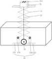
图1A和图1B示出了一种自动充电画屏显示装置示意图。1A and 1B show a schematic diagram of an automatic charging picture screen display device.
该画屏显示终端(厚度约38mm)的背面集成有电机(厚度约48mm)、电池(厚度约29mm)、充电线卷轴装置(厚度约48mm),大大增加了显示终端的厚度,使得整机厚度达到91mm;其中尤其是卷轴装置的厚度,对整机厚度增加影响较大。显示终端下方地面上设置有充电底座,充电线卷轴装置的充电头拉伸出与充电底座实现电连接从而完成充电。根据目前市场情况,充电线卷轴装置的厚度无法实现更薄,故目前自动充电式画屏显示终端的厚度无法实现轻薄化。The back of the screen display terminal (thickness about 38mm) is integrated with a motor (thickness about 48mm), battery (thickness about 29mm), charging cable reel device (thickness about 48mm), which greatly increases the thickness of the display terminal, making the thickness of the whole machine reach 91mm; in particular, the thickness of the reel device has a great influence on the increase of the thickness of the whole machine. A charging base is arranged on the ground below the display terminal, and the charging head of the charging cable reel device is pulled out to be electrically connected to the charging base to complete charging. According to the current market situation, the thickness of the charging cable reel device cannot be thinner, so the thickness of the current automatic charging type picture screen display terminal cannot be thinned.
本发明实施例的第一个方面,提出了一种充电装置,能够在一定程度上实现待充电设备的轻薄化。In a first aspect of the embodiments of the present invention, a charging device is provided, which can achieve a light and thin device to be charged to a certain extent.
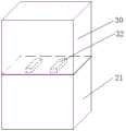
如图2所示,所述充电装置,包括伸缩装置10和充电单元20;所述充电单元20包括用于与待充电设备30电连接的充电头21(参考图3B和3C);所述充电头21连接所述伸缩装置10,所述伸缩装置10在伸缩方向上长度可调,所述伸缩装置10被配置为沿所述伸缩方向带动所述充电头21运动。As shown in FIG. 2 , the charging device includes a
可选地,如图3A所示,为本发明实施例中待充电设备30(可选地为画屏显示装置)的示意图。可见,在设置了本发明实施例的充电装置后,所述待充电设备30的背后只需要设置电池和相应的充电插座即可,通过将充电触点设置在所述待充电设备30下侧的充电插座以与充电装置的充电头21进行电连接,即可完成充电。Optionally, as shown in FIG. 3A , it is a schematic diagram of a device to be charged 30 (optionally a screen display device) in an embodiment of the present invention. It can be seen that after the charging device according to the embodiment of the present invention is installed, the back of the
如图3B所示为本发明实施例提供的充电装置在未对待充电设备进行充电的情形下的示意图。通过将待充电设备30和充电装置分开设置,独立的充电装置与充电底座集成。当待充电设备30需要充电时,充电装置内的伸缩装置10将充电头21伸出,连接到待充电设备30下侧的充电插座的充电触点,进行充电,如图3C所示。充完电,伸缩装置10将充电头21收回来并收起。FIG. 3B is a schematic diagram of the charging apparatus provided by the embodiment of the present invention in a situation where the device to be charged is not charged. By disposing the device to be charged 30 and the charging device separately, the independent charging device is integrated with the charging base. When the device to be charged 30 needs to be charged, the
从上述实施例可以看出,本发明实施例提供的充电装置,通过设置伸缩装置将充电头伸出以与待充电设备电连接,从而实现充电,使得待充电设备无需再设置卷轴装置,大大减小了待充电设备的厚度,从而实现待充电设备的轻薄化。It can be seen from the above embodiments that, in the charging device provided by the embodiment of the present invention, the charging head is extended to be electrically connected with the device to be charged by providing a telescopic device, so as to realize charging, so that the device to be charged does not need to be provided with a reel device, which greatly reduces the need for charging. The thickness of the device to be charged is reduced, thereby realizing the thinning of the device to be charged.
可选地,所述伸缩装置10包括伸缩部件和驱动部件;所述伸缩部件的端部设置所述充电头21;所述伸缩部件在伸缩方向上长度可调,所述驱动部件用于带动所述伸缩部件实现伸缩,进而带动所述充电头运动。Optionally, the
作为本发明的一个实施例,如图4A和4B所示,所述伸缩装置10包括交叉式伸缩臂11,所述交叉式伸缩臂11的第一端连接所述驱动部件12,所述交叉式伸缩臂11的第二端连接所述充电头21,所述交叉式伸缩臂11在所述驱动部件12的带动下实现伸缩;这样,当需要进行充电时,所述驱动部件12带动所述交叉式伸缩臂11伸出,进而将所述充电头21伸出,使充电头21与待充电设备30实现电连接,从而完成充电;当完成充电后,驱动部件12再带动所述交叉式伸缩臂11收起,从而将充电头21收起。As an embodiment of the present invention, as shown in FIGS. 4A and 4B , the
作为一个可选实施方式,如图4A和4B所示,所述驱动部件12包括第一微调柱121、第二微调柱122、第一导轨123和第二导轨124;所述交叉式伸缩臂11的第一端的第一支脚连接所述第一微调柱121,所述交叉式伸缩臂11的第一端的第二支脚连接所述第二微调柱122;所述第一导轨123和第二导轨124的轴线均处在所述交叉式伸缩臂11的所在平面内;所述第一微调柱121和第二微调柱122分别设置在所述第一导轨123和第二导轨124中并能够分别沿所述第一导轨123和第二导轨124运动以带动所述交叉式伸缩臂11实现伸缩。As an optional embodiment, as shown in FIGS. 4A and 4B , the driving
具体地,如图4A所示,当所述第一微调柱121和第二微调柱122的相对距离较远时,所述第一微调柱121和第二微调柱122分别拉动所述交叉式伸缩臂11的第一端的第一支脚和第二支脚,从而使所述交叉式伸缩臂11收缩,进而收起充电头。如图4B所示,当所述第一微调柱121和第二微调柱122的相对距离较近时,所述第一微调柱121和第二微调柱122分别推动所述交叉式伸缩臂11的第一端的第一支脚和第二支脚,从而使所述交叉式伸缩臂11伸出,进而将所述充电头伸出以与待充电设备30电连接。Specifically, as shown in FIG. 4A , when the relative distance between the first fine-
可选地,如图5A和5B所示,所述驱动部件12还包括第一电机(未示出)、第二电机(未示出)、第一转轴125、第二转轴(未示出)、第一刚性直杆126和第二刚性直杆(未示出);Optionally, as shown in FIGS. 5A and 5B , the driving
所述第一刚性直杆126处在所述第一转轴125的旋转面内,所述第一转轴125的旋转面处在所述交叉式伸缩臂11的所在平面内;所述第一刚性直杆126的第一端连接所述第一转轴126的外边缘,所述第一刚性直杆126的第二端连接所述第一微调柱121;所述第一电机连接所述第一转轴125的轴心,用于驱动所述第一转轴125旋转,使得所述第一刚性直杆126被所述第一转轴125拉动或推动,进而拉动或推动所述第一微调柱121;可选的,当所述第一转轴125为椭圆形时,能够增大所述第一刚性直杆126推动所述第一微调柱的行程,更便于调节;但是,可以知道,当第一转轴125为圆形时,同样能够实现带动第一刚性直杆126运动的效果,只是行程较第一转轴125为椭圆形时更短而已,因此,所述第一转轴125的形状可以不做限制,只需满足使用需求即可;The first rigid
所述第二刚性直杆处在所述第二转轴的旋转面内,所述第二转轴的旋转面处在所述交叉式伸缩臂11的所在平面内;所述第二刚性直杆的第一端连接所述第二转轴的外边缘,所述第二刚性直杆的第二端连接所述第二微调柱122;所述第二电机连接所述第二转轴的轴心,用于驱动所述第二转轴旋转,使得所述第二刚性直杆被所述第二转轴拉动或推动,进而拉动或推动所述第二微调柱122;可选的,当所述第二转轴为椭圆形时,能够增大所述第二刚性直杆推动所述第二微调柱的行程,更便于调节;但是,可以知道,当第二转轴为圆形时,同样能够实现带动第二刚性直杆运动的效果,只是行程较第二转轴为椭圆形时更短而已,因此,所述第二转轴的形状可以不做限制,只需满足使用需求即可。The second rigid straight rod is located in the rotation surface of the second rotating shaft, and the rotating surface of the second rotating shaft is located in the plane of the cross-type
可选地,如图6所示,所述驱动部件12还包括第一移动平台127、第二移动平台(未示出)、第三电机(未示出)、第四电机(未示出)、第一齿轮128和第二齿轮(未示出);Optionally, as shown in FIG. 6 , the driving
所述第一微调柱121设置在所述第一移动平台127上;所述第一移动平台127的底部具有第一锯齿状表面,所述第一齿轮128能够与所述第一锯齿状表面啮合,所述第三电机连接所述第一齿轮128的中心,用于驱动所述第一齿轮128旋转以带动所述第一移动平台127移动,使得位于所述第一移动平台127上的所述第一微调柱随之移动;The first
所述第二微调柱设置在所述第二移动平台上;所述第二移动平台的底部具有第二锯齿状表面,所述第二齿轮能够与所述第二锯齿状表面啮合,所述第四电机连接所述第二齿轮的中心,用于驱动所述第二齿轮旋转以带动所述第二移动平台移动,使得位于所述第二移动平台上的所述第二微调柱随之移动。The second fine adjustment column is arranged on the second moving platform; the bottom of the second moving platform has a second sawtooth surface, the second gear can be engaged with the second sawtooth surface, and the first Four motors are connected to the center of the second gear for driving the second gear to rotate to drive the second moving platform to move, so that the second fine-tuning column on the second moving platform moves accordingly.
可选地,上述第一电机、第二电机、第三电机和第四电机均可选用步进电机,当然其他类型的电机也可以适用,此处不做具体限定。Optionally, the first motor, the second motor, the third motor and the fourth motor can all be selected as stepper motors. Of course, other types of motors are also applicable, which are not specifically limited here.
以上驱动部件12的两种调节方式均能较好地实现微调柱的位置调节。可以知道的是,除了这两种调节方式外,本领域还有很多其他的调节机构均可用于本发明中,这些替代方式也均属于本发明的保护范围。Both of the above two adjustment methods of the driving
作为本发明的另一个实施例,如图7A和7B所示,所述伸缩部件为伸缩杆13,所述伸缩杆13为多节结构(图中所示为三节,实际可以根据需要设置更多或更少节),多节杆体之间互相嵌套形成所述伸缩杆,每节杆体均收回时(如图7A所示),此时伸缩杆13的长度最短,每节杆体均伸出时(如图7B所示),此时伸缩杆13的长度最长;所述驱动部件包括丝杆129和第五电机1210;所述伸缩杆13的第一端131的内部连接所述丝杆129的第一端(如图7A和7B所示,丝杆129的第一端位于所述伸缩杆13内部并与伸缩杆13的第一端131连接),所述伸缩杆13的第一端131的外端部连接所述充电头21(如图7B所示),所述伸缩杆13的第二端132固定在所述伸缩装置10上;所述第五电机1210的外周面设置有第一齿1210a,所述丝杆129靠近其第二端的外表面设置有第二齿129a,所述第一齿1210a与所述第二齿129a啮合,使得所述第五电机1210转动时,带动所述丝杆129在所述伸缩杆13的伸缩方向上运动,进而带动所述伸缩杆13实现伸缩。As another embodiment of the present invention, as shown in FIGS. 7A and 7B , the telescopic component is a
以上交叉式伸缩臂和伸缩杆的伸缩装置实施例,均能较好地实现将充电头21伸出和收起的效果。可以知道的是,除了这两种伸缩方式外,本领域还有很多其他的伸缩机构均可用于本发明中,这些替代方式也均属于本发明的保护范围。The above embodiments of the telescopic device of the cross-type telescopic arm and the telescopic rod can better achieve the effect of extending and retracting the charging
可选地,如图4A和7A所示,所述充电单元20还包括线圈机构和电源模块(未示出);所述线圈机构包括连接线22和绕线轴23,所述连接线22的第一端连接所述充电头21,所述连接线22的第二端连接所述电源模块并能卷收于所述绕线轴23,所述连接线22被配置为在所述伸缩装置10的带动下在所述伸缩方向上延伸。这样,通过线圈机构实现连接线的卷收,能够节约充电装置的内部空间。所述电源模块可以为电池。Optionally, as shown in FIGS. 4A and 7A , the charging
可选地,所述充电头21与待充电设备30在电连接时可以采用充电触点连接的方式,如图8A和8B所示,所述充电头21的顶部设置充电触点211,所述待充电设备30的底部设置充电触点31,当充电触点211与充电触点31接触时,实现电连接。较佳地,所述充电头21的顶部设置有凸起,所述充电触点211设置在所述凸起上,所述待充电设备30的底部设置充电槽,所述充电触点31设置在所述充电槽底部,所述凸起与充电槽卡接配合时,充电触点211与充电触点31接触,实现电连接,如图9A和9B所示,这样,能够保证充电触点211与充电触点31之间不错位,提高充电稳定性。Optionally, the charging
作为本发明的一个可选实施例,如图10所示,所述充电装置还包括通讯单元40和控制单元50;As an optional embodiment of the present invention, as shown in FIG. 10 , the charging device further includes a communication unit 40 and a
所述通讯单元40,用于接收充电请求;可选地,所述通讯单元40可以是无线通信模块实现的;所述无线通信模块可以是GPRS移动通信模块、Zigbee模块、WIFI模块、蓝牙模块等;The communication unit 40 is used to receive a charging request; optionally, the communication unit 40 may be implemented by a wireless communication module; the wireless communication module may be a GPRS mobile communication module, a Zigbee module, a WIFI module, a Bluetooth module, etc. ;
所述控制单元50,用于根据所述充电请求控制所述伸缩装置10伸出,以使所述充电头21与所述待充电设备30实现电连接,以及,控制所述充电单元20向所述待充电设备30充电;可选地,所述控制单元50可以是CPU或MCU实现的。The
当待充电设备30需要充电时,待充电设备30发出充电请求,所述通讯单元40接收该充电请求,所述控制单元50控制所述伸缩装置10慢慢伸出,以使所述充电头21与所述待充电设备30实现电连接,当检测到开始充电后,控制所述充电单元20向所述待充电设备30充电。When the device to be charged 30 needs to be charged, the device to be charged 30 sends a charging request, the communication unit 40 receives the charging request, and the
可选地,所述充电装置可以设置检测是否与待充电设备完成电连接并开启充电过程的步骤,具体地,可以通过检测充电触点的电压变化来实现,在此不再赘述。Optionally, the charging device may be provided with a step of detecting whether the electrical connection with the device to be charged is completed and the charging process is started.
可选地,可以在所述伸缩装置10或者待充电设备30下方设置传感器(压力传感器、光学传感器等),用于判断所述伸缩装置10是否到达充电的位置,如果位置有偏差,可以进行上下微调。Optionally, a sensor (a pressure sensor, an optical sensor, etc.) may be provided under the
如图10所示,所述充电装置还包括移动机构60;可选地,所述移动机构60包括驱动单元和四个万向轮61,所述四个万向轮61设置在所述充电装置的底部四个角上,所述驱动单元用于在控制单元50的控制下驱动所述万向轮向61指定方向转动,以实现所述充电装置的移动;As shown in FIG. 10 , the charging device further includes a moving
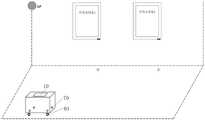
所述控制单元50,还用于根据所述充电请求(包括待充电设备的地址坐标)确定所述待充电设备30的位置,并控制所述移动机构60带动所述充电装置移动到所述待充电设备的充电位置;例如,如图11B所示,将所述充电装置移动到待充电设备的下方,通过伸缩装置10将充电头21升起并与待充电设备底部的充电触点接触,从而实现电连接并完成充电。这样,通过移动机构60带动充电装置移动到指定地点实现充电,使得充电装置更加智能化。对于画廊场景或者有很多待充电设备同时展示的场景,无需每个待充电设备配备一个充电装置,大大降低了成本。The
图11A和图11B示出了本发明实施例中可移动式充电装置的应用场景示意图。所述充电装置可以在初始时设置在一个特定的角落或固定位置,待充电设备的通讯模块通过网关AP给充电装置发送充电请求,充电装置移动至需要待充电设备下方,接着通过伸缩装置10将充电头21升起,充电头21与待充电设备的充电触点相互接触,进而进行充电。FIG. 11A and FIG. 11B show schematic diagrams of application scenarios of the portable charging device in the embodiment of the present invention. The charging device can be initially set in a specific corner or a fixed position, the communication module of the device to be charged sends a charging request to the charging device through the gateway AP, the charging device is moved to the bottom of the device to be charged, and then the
可选地,所述充电装置内可以设置移动电源,便于充电。Optionally, a mobile power supply can be provided in the charging device to facilitate charging.
可选地,所述控制单元50,还用于在所述充电头21与所述待充电设备30实现电连接时,控制所述移动机构60实现抱死。这样,在充电状态下抱死移动机构60,保证充电过程的稳定性。较佳地,所述控制单元50,还用于在所述充电头21与所述待充电设备30实现电连接时,控制所述伸缩装置10抱死,进一步保证充电过程的稳定性。Optionally, the
如图10所示,所述充电装置还包括识别单元70,用于识别并定位所述待充电设备30,从而所述充电装置实现精确定位待充电设备。As shown in FIG. 10 , the charging device further includes an
可选地,所述识别单元70为射频识别(RFID)定位模块。具体地,每个待充电设备的充电位置都设置有RFID标签(例如,设置在待充电设备下方的地面上),用以与所述充电装置的识别单元70进行信息交互,从而实现精确定位。可选地,所述充电装置底部四角各设置一个RFID读卡器(识别单元70)用以识别所述RFID标签。Optionally, the
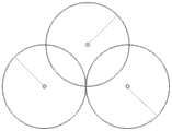
可选地,所述识别单元70,用于通过距离估计法实现所述待充电设备30的定位。距离估计法是利用三角形的特点来估计待定位体的位置的算法,包括三角测量法和三边测量法。如图12A所示,三角测量法通过测量不少于两个参考点所接收信号的到达角度,形成角度的两条直线的交点即是所估计的位置。如图12B所示,三边测量法通过测量待定位点到至少3个参考点的距离来估计待定位点的位置。这种测量技术利用接收信号接度(ReceivedSignal Strength,RSS)、信号到达时间(Time Of Arrival,TOA)、信号到达时间差(TimeDifference Of Arrival,TDOA)和接收信号相位(Received Signal Phase,RSP)等方法。Optionally, the identifying
(1)RSS:发射信号强度的衰减与发射机和接收机之间的距离成函数关系。依据相应的传播信号路径损耗,把信号强度转化为距离进行定位,待定位点最少需要3个参考点参与计算。基于RSS的系统通常需要自适应机制以减少室内环境下多径衰落及阴影效应的影响。(1) RSS: The attenuation of the transmitted signal strength is a function of the distance between the transmitter and the receiver. According to the corresponding propagation signal path loss, the signal strength is converted into distance for positioning, and at least 3 reference points are required to participate in the calculation of the to-be-located point. RSS-based systems usually require adaptive mechanisms to reduce the effects of multipath fading and shadowing effects in indoor environments.
(2)TOA:参考点与待定位点的距离与信号的传播时间成比例关系。基于到达时间的系统最少需要3个不同的测量装置来完成二维定位。TOA系统要求所有的发射机和接收机之间保持时间同步。如果有多个参考点,采用最小平方算法以减少定位误差。(2) TOA: The distance between the reference point and the point to be located is proportional to the propagation time of the signal. A time-of-arrival-based system requires a minimum of 3 different measurement devices to complete 2D positioning. TOA systems require time synchronization between all transmitters and receivers. If there are multiple reference points, the least squares algorithm is used to reduce the positioning error.
(3)TDOA:依据待定位点发射信号到达多个测量装置的时间不同,把时间差转化为距离差,以确定待定位点的相对位置。TDOA方法至少需要3个测量装置参与距离差的测量,要求测量装置之间保持时间同步。(3) TDOA: According to the difference in the time when the signal transmitted by the point to be located reaches multiple measuring devices, the time difference is converted into a distance difference to determine the relative position of the point to be located. The TDOA method requires at least three measurement devices to participate in the distance difference measurement, and requires time synchronization between the measurement devices.
(4)RSP:采用信号波长分式表示时延来估计距离。这种方法要求发射机放在特定位置并且假设发射机发射完全正弦信号。利用和TOA相同的算法测量相位值估计位置,也可以利用和TDOA相同的算法测量相位差值实现定位。(4) RSP: Use the signal wavelength fraction to express the time delay to estimate the distance. This method requires the transmitter to be placed at a specific location and assumes that the transmitter emits a fully sinusoidal signal. Use the same algorithm as TOA to measure the phase value to estimate the position, and you can also use the same algorithm as TDOA to measure the phase difference value to achieve positioning.
(5)AOA:主要利用方向天线或阵列天线测量待定位点信号直线到达接收机的角度信息来确定待定位点的位置。(5) AOA: The directional antenna or array antenna is mainly used to measure the angle information of the signal of the point to be located in a straight line reaching the receiver to determine the position of the point to be located.
本发明实施例的第二个方面,提出了一种待充电设备的控制方法,能够在一定程度上实现轻薄化。In a second aspect of the embodiments of the present invention, a method for controlling a device to be charged is provided, which can achieve lightness and thickness to a certain extent.
所述待充电设备,包括充电插座,所述充电插座与所述充电装置的充电头21插接配合,当所述充电头与所述充电插座电连接时,所述充电装置为所述待充电设备充电。The device to be charged includes a charging socket, which is plugged and matched with the charging
从上述实施例可以看出,本发明实施例提供的待充电设备,通过卷轴装置设置在充电装置中,使得待充电设备无需再设置卷轴装置,大大减小了待充电设备的厚度,从而实现待充电设备的轻薄化。It can be seen from the above embodiments that the device to be charged provided by the embodiment of the present invention is arranged in the charging device through a reel device, so that the device to be charged does not need to be provided with a reel device, and the thickness of the device to be charged is greatly reduced, thereby realizing the realization of the device to be charged. Thinning of charging equipment.
本发明实施例的第三个方面,提出了一种充电装置的控制方法,能够在一定程度上实现待充电设备的轻薄化。In a third aspect of the embodiments of the present invention, a method for controlling a charging device is provided, which can achieve a light and thin device to be charged to a certain extent.
如图13所示,应用于所述充电装置的任一实施例或实施例的排列、组合的控制方法,包括:As shown in FIG. 13 , the control method applied to any embodiment of the charging device or the arrangement or combination of the embodiments includes:
步骤81:接收充电请求;Step 81: Receive a charging request;
步骤82:根据所述充电请求控制所述伸缩装置伸出,以使所述充电头与所述待充电设备实现电连接;Step 82: controlling the telescopic device to extend according to the charging request, so as to realize electrical connection between the charging head and the device to be charged;
步骤83:在所述充电头与所述待充电设备实现电连接后,控制所述充电单元向所述待充电设备充电。Step 83: After the charging head is electrically connected to the device to be charged, control the charging unit to charge the device to be charged.
可选地,所述充电装置可以设置检测是否与待充电设备完成电连接并开启充电过程的步骤,具体地,可以通过检测充电触点的电压变化来实现,在此不再赘述。Optionally, the charging device may be provided with a step of detecting whether the electrical connection with the device to be charged is completed and the charging process is started.
从上述实施例可以看出,本发明实施例提供的充电装置的控制方法,通过设置伸缩装置将充电头伸出以与待充电设备电连接,从而实现充电,使得待充电设备无需再设置卷轴装置,大大减小了待充电设备的厚度,从而实现待充电设备的轻薄化。It can be seen from the above embodiments that, in the control method of the charging device provided by the embodiment of the present invention, the charging head is extended to be electrically connected with the device to be charged by setting the telescopic device, so as to realize charging, so that the device to be charged does not need to be provided with a reel device. , which greatly reduces the thickness of the device to be charged, thereby realizing the thinning of the device to be charged.
作为本发明的一个实施例,当所述待充电设备充满电后,所述待充电设备向所述充电装置发送断电请求,所述充电装置的控制方法则还可包括以下步骤:As an embodiment of the present invention, after the device to be charged is fully charged, the device to be charged sends a power-off request to the charging device, and the control method of the charging device may further include the following steps:
接收所述待充电设备发出的断电请求;receiving a power-off request sent by the device to be charged;
根据所述断电请求控制所述伸缩装置收回,以使所述充电头与所述待充电设备断开电连接。The retractable device is controlled to retract according to the power-off request, so that the charging head is electrically disconnected from the device to be charged.
通过上述方式,能够全自动地完成待充电设备的充电过程,无需人工辅助或干预。In the above manner, the charging process of the device to be charged can be completed automatically without manual assistance or intervention.
作为本发明的一个实施例,所述充电装置还包括移动机构60(参考图10),所述充电装置的控制方法还包括:As an embodiment of the present invention, the charging device further includes a moving mechanism 60 (refer to FIG. 10 ), and the control method of the charging device further includes:
根据所述充电请求确定所述待充电设备的位置;determining the location of the device to be charged according to the charging request;
控制所述移动机构带动所述充电装置移动到所述待充电设备的充电位置。The moving mechanism is controlled to drive the charging device to move to the charging position of the device to be charged.
例如,如图11B所示,将所述充电装置移动到待充电设备的下方,通过伸缩装置10将充电头21升起并与待充电设备底部的充电触点接触,从而实现电连接并完成充电。这样,通过移动机构60带动充电装置移动到指定地点实现充电,使得充电装置更加智能化。对于画廊场景或者有很多待充电设备同时展示的场景,无需每个待充电设备配备一个充电装置,大大降低了成本。For example, as shown in FIG. 11B , the charging device is moved below the device to be charged, and the charging
作为本发明的一个实施例,所述充电装置的控制方法,还包括:在所述充电头与所述待充电设备实现电连接时,控制所述移动机构实现抱死。这样,在充电状态下抱死移动机构60,保证充电过程的稳定性。较佳地,所述控制单元50,还用于在所述充电头21与所述待充电设备30实现电连接时,控制所述伸缩装置10抱死,进一步保证充电过程的稳定性。As an embodiment of the present invention, the method for controlling the charging device further includes: when the charging head is electrically connected to the device to be charged, controlling the moving mechanism to lock. In this way, the moving
作为本发明的一个实施例,所述充电装置的控制方法,还包括:通过距离估计法实现所述待充电设备的定位。距离估计法是利用三角形的特点来估计待定位体的位置的算法,包括三角测量法和三边测量法。如图12A所示,三角测量法通过测量不少于两个参考点所接收信号的到达角度,形成角度的两条直线的交点即是所估计的位置。如图12B所示,三边测量法通过测量待定位点到至少3个参考点的距离来估计待定位点的位置。这种测量技术利用接收信号接度(Received Signal Strength,RSS)、信号到达时间(Time OfArrival,TOA)、信号到达时间差(Time Difference Of Arrival,TDOA)和接收信号相位(Received Signal Phase,RSP)等方法。As an embodiment of the present invention, the control method of the charging device further includes: realizing the positioning of the device to be charged by using a distance estimation method. Distance estimation is an algorithm that uses the characteristics of triangles to estimate the position of the object to be located, including triangulation and trilateration. As shown in FIG. 12A , the triangulation method measures the arrival angle of the received signal at no less than two reference points, and the intersection of the two straight lines forming the angle is the estimated position. As shown in FIG. 12B , the trilateration method estimates the position of the to-be-located point by measuring the distance from the to-be-located point to at least three reference points. This measurement technique utilizes Received Signal Strength (RSS), Time Of Arrival (TOA), Time Difference Of Arrival (TDOA), and Received Signal Phase (RSP), etc. method.
此外,典型地,本公开所述的装置、设备等可为各种电子终端设备,例如手机、个人数字助理(PDA)、平板电脑(PAD)、智能电视等,也可以是大型终端设备,如服务器等,因此本公开的保护范围不应限定为某种特定类型的装置、设备。本公开所述的客户端可以是以电子硬件、计算机软件或两者的组合形式应用于上述任意一种电子终端设备中。In addition, typically, the apparatuses, devices, etc. described in the present disclosure can be various electronic terminal devices, such as mobile phones, personal digital assistants (PDAs), tablet computers (PADs), smart TVs, etc., and can also be large-scale terminal devices, such as Servers, etc. Therefore, the protection scope of the present disclosure should not be limited to a certain type of apparatus or equipment. The client described in the present disclosure may be applied to any of the above electronic terminal devices in the form of electronic hardware, computer software, or a combination of the two.
此外,根据本公开的方法还可以被实现为由CPU执行的计算机程序,该计算机程序可以存储在计算机可读存储介质中。在该计算机程序被CPU执行时,执行本公开的方法中限定的上述功能。Furthermore, the method according to the present disclosure can also be implemented as a computer program executed by a CPU, and the computer program can be stored in a computer-readable storage medium. When the computer program is executed by the CPU, the above-described functions defined in the method of the present disclosure are performed.
此外,上述方法步骤以及系统单元也可以利用控制器以及用于存储使得控制器实现上述步骤或单元功能的计算机程序的计算机可读存储介质实现。In addition, the above-mentioned method steps and system units can also be implemented by using a controller and a computer-readable storage medium for storing a computer program that enables the controller to implement the functions of the above-mentioned steps or units.
此外,应该明白的是,本文所述的计算机可读存储介质(例如,存储器)可以是易失性存储器或非易失性存储器,或者可以包括易失性存储器和非易失性存储器两者。作为例子而非限制性的,非易失性存储器可以包括只读存储器(ROM)、可编程ROM(PROM)、电可编程ROM(EPROM)、电可擦写可编程ROM(EEPROM)或快闪存储器。易失性存储器可以包括随机存取存储器(RAM),该RAM可以充当外部高速缓存存储器。作为例子而非限制性的,RAM可以以多种形式获得,比如同步RAM(DRAM)、动态RAM(DRAM)、同步DRAM(SDRAM)、双数据速率SDRAM(DDR SDRAM)、增强SDRAM(ESDRAM)、同步链路DRAM(SLDRAM)以及直接RambusRAM(DRRAM)。所公开的方面的存储设备意在包括但不限于这些和其它合适类型的存储器。In addition, it should be understood that computer-readable storage media (eg, memory) described herein can be volatile memory or nonvolatile memory, or can include both volatile and nonvolatile memory. By way of example and not limitation, nonvolatile memory may include read only memory (ROM), programmable ROM (PROM), electrically programmable ROM (EPROM), electrically erasable programmable ROM (EEPROM), or flash memory memory. Volatile memory may include random access memory (RAM), which may act as external cache memory. By way of example and not limitation, RAM is available in various forms such as Synchronous RAM (DRAM), Dynamic RAM (DRAM), Synchronous DRAM (SDRAM), Double Data Rate SDRAM (DDR SDRAM), Enhanced SDRAM (ESDRAM), Synchronous Link DRAM (SLDRAM) and Direct RambusRAM (DRRAM). The storage devices of the disclosed aspects are intended to include, but not be limited to, these and other suitable types of memory.
本领域技术人员还将明白的是,结合这里的公开所描述的各种示例性逻辑块、模块、电路和算法步骤可以被实现为电子硬件、计算机软件或两者的组合。为了清楚地说明硬件和软件的这种可互换性,已经就各种示意性组件、方块、模块、电路和步骤的功能对其进行了一般性的描述。这种功能是被实现为软件还是被实现为硬件取决于具体应用以及施加给整个系统的设计约束。本领域技术人员可以针对每种具体应用以各种方式来实现所述的功能,但是这种实现决定不应被解释为导致脱离本公开的范围。Those skilled in the art will also appreciate that the various exemplary logical blocks, modules, circuits, and algorithm steps described in connection with the disclosure herein may be implemented as electronic hardware, computer software, or combinations of both. To clearly illustrate this interchangeability of hardware and software, various illustrative components, blocks, modules, circuits, and steps have been described generally in terms of their functionality. Whether such functionality is implemented as software or hardware depends on the specific application and design constraints imposed on the overall system. Skilled artisans may implement the described functionality in various ways for each particular application, but such implementation decisions should not be interpreted as causing a departure from the scope of the present disclosure.
结合这里的公开所描述的各种示例性逻辑块、模块和电路可以利用被设计成用于执行这里所述功能的下列部件来实现或执行:通用处理器、数字信号处理器(DSP)、专用集成电路(ASIC)、现场可编程门阵列(FPGA)或其它可编程逻辑器件、分立门或晶体管逻辑、分立的硬件组件或者这些部件的任何组合。通用处理器可以是微处理器,但是可替换地,处理器可以是任何传统处理器、控制器、微控制器或状态机。处理器也可以被实现为计算设备的组合,例如,DSP和微处理器的组合、多个微处理器、一个或多个微处理器结合DSP核、或任何其它这种配置。The various exemplary logical blocks, modules, and circuits described in connection with the disclosure herein may be implemented or performed using the following components designed to perform the functions described herein: general purpose processors, digital signal processors (DSPs), special purpose processors Integrated Circuits (ASICs), Field Programmable Gate Arrays (FPGAs) or other programmable logic devices, discrete gate or transistor logic, discrete hardware components, or any combination of these components. A general-purpose processor may be a microprocessor, but in the alternative, the processor may be any conventional processor, controller, microcontroller, or state machine. A processor may also be implemented as a combination of computing devices, eg, a combination of a DSP and a microprocessor, multiple microprocessors, one or more microprocessors combined with a DSP core, or any other such configuration.
结合这里的公开所描述的方法或算法的步骤可以直接包含在硬件中、由处理器执行的软件模块中或这两者的组合中。软件模块可以驻留在RAM存储器、快闪存储器、ROM存储器、EPROM存储器、EEPROM存储器、寄存器、硬盘、可移动盘、CD-ROM、或本领域已知的任何其它形式的存储介质中。示例性的存储介质被耦合到处理器,使得处理器能够从该存储介质中读取信息或向该存储介质写入信息。在一个替换方案中,所述存储介质可以与处理器集成在一起。处理器和存储介质可以驻留在ASIC中。ASIC可以驻留在用户终端中。在一个替换方案中,处理器和存储介质可以作为分立组件驻留在用户终端中。The steps of a method or algorithm described in connection with the disclosures herein may be embodied directly in hardware, in a software module executed by a processor, or in a combination of the two. A software module may reside in RAM memory, flash memory, ROM memory, EPROM memory, EEPROM memory, registers, hard disk, removable disk, CD-ROM, or any other form of storage medium known in the art. An exemplary storage medium is coupled to the processor, such that the processor can read information from, and write information to, the storage medium. In an alternative, the storage medium may be integrated with the processor. The processor and storage medium may reside in an ASIC. The ASIC may reside in the user terminal. In an alternative, the processor and storage medium may reside in the user terminal as discrete components.
在一个或多个示例性设计中,所述功能可以在硬件、软件、固件或其任意组合中实现。如果在软件中实现,则可以将所述功能作为一个或多个指令或代码存储在计算机可读介质上或通过计算机可读介质来传送。计算机可读介质包括计算机存储介质和通信介质,该通信介质包括有助于将计算机程序从一个位置传送到另一个位置的任何介质。存储介质可以是能够被通用或专用计算机访问的任何可用介质。作为例子而非限制性的,该计算机可读介质可以包括RAM、ROM、EEPROM、CD-ROM或其它光盘存储设备、磁盘存储设备或其它磁性存储设备,或者是可以用于携带或存储形式为指令或数据结构的所需程序代码并且能够被通用或专用计算机或者通用或专用处理器访问的任何其它介质。此外,任何连接都可以适当地称为计算机可读介质。例如,如果使用同轴线缆、光纤线缆、双绞线、数字用户线路(DSL)或诸如红外线、无线电和微波的无线技术来从网站、服务器或其它远程源发送软件,则上述同轴线缆、光纤线缆、双绞线、DSL或诸如红外先、无线电和微波的无线技术均包括在介质的定义。如这里所使用的,磁盘和光盘包括压缩盘(CD)、激光盘、光盘、数字多功能盘(DVD)、软盘、蓝光盘,其中磁盘通常磁性地再现数据,而光盘利用激光光学地再现数据。上述内容的组合也应当包括在计算机可读介质的范围内。In one or more exemplary designs, the functions may be implemented in hardware, software, firmware, or any combination thereof. If implemented in software, the functions may be stored on or transmitted over as one or more instructions or code on a computer-readable medium. Computer-readable media includes both computer storage media and communication media including any medium that facilitates transfer of a computer program from one place to another. A storage medium can be any available medium that can be accessed by a general purpose or special purpose computer. By way of example and not limitation, the computer-readable medium may include RAM, ROM, EEPROM, CD-ROM or other optical disk storage devices, magnetic disk storage devices or other magnetic storage devices, or may be used to carry or store instructions in the form of or data structures and any other medium that can be accessed by a general purpose or special purpose computer or a general purpose or special purpose processor. Also, any connection is properly termed a computer-readable medium. For example, if coaxial cable, fiber optic cable, twisted pair, digital subscriber line (DSL), or wireless technologies such as infrared, radio, and microwave are used to send software from a website, server, or other remote source, the above coaxial cable Cable, fiber optic cable, twisted pair, DSL or wireless technologies such as infrared, radio and microwave are included in the definition of medium. As used herein, magnetic disks and optical disks include compact disks (CDs), laser disks, optical disks, digital versatile disks (DVDs), floppy disks, blu-ray disks, where disks usually reproduce data magnetically, while optical disks reproduce data optically with lasers . Combinations of the above should also be included within the scope of computer-readable media.
公开的示例性实施例,但是应当注公开的示例性实施例,但是应当注意,在不背离权利要求限定的本公开的范围的前提下,可以进行多种改变和修改。根据这里描述的公开实施例的方法权利要求的功能、步骤和/或动作不需以任何特定顺序执行。此外,尽管本公开的元素可以以个体形式描述或要求,但是也可以设想多个,除非明确限制为单数。Disclosed exemplary embodiments, but it should be noted that disclosed exemplary embodiments, however, it should be noted that various changes and modifications can be made without departing from the scope of the present disclosure as defined by the claims. The functions, steps and/or actions of the method claims in accordance with the disclosed embodiments described herein need not be performed in any particular order. Furthermore, although elements of the present disclosure may be described or claimed in the singular, the plural is also contemplated unless explicitly limited to the singular.
应当理解的是,在本文中使用的,除非上下文清楚地支持例外情况,单数形式“一个”(“a”、“an”、“the”)旨在也包括复数形式。还应当理解的是,在本文中使用的“和/或”是指包括一个或者一个以上相关联地列出的项目的任意和所有可能组合。It should be understood that, as used herein, the singular forms "a" ("a", "an", "the") are intended to include the plural forms as well, unless the context clearly supports an exception. It will also be understood that "and/or" as used herein is meant to include any and all possible combinations of one or more of the associated listed items.
上述本公开实施例序号仅仅为了描述,不代表实施例的优劣。The above-mentioned serial numbers of the embodiments of the present disclosure are only for description, and do not represent the advantages or disadvantages of the embodiments.
本领域普通技术人员可以理解实现上述实施例的全部或部分步骤可以通过硬件来完成,也可以通过程序来指令相关的硬件完成,所述的程序可以存储于一种计算机可读存储介质中,上述提到的存储介质可以是只读存储器,磁盘或光盘等。Those of ordinary skill in the art can understand that all or part of the steps of implementing the above embodiments can be completed by hardware, or can be completed by instructing relevant hardware through a program, and the program can be stored in a computer-readable storage medium. The storage medium mentioned may be a read-only memory, a magnetic disk or an optical disk, etc.
所属领域的普通技术人员应当理解:以上任何实施例的讨论仅为示例性的,并非旨在暗示本公开的范围(包括权利要求)被限于这些例子;在本发明实施例的思路下,以上实施例或者不同实施例中的技术特征之间也可以进行组合,并存在如上所述的本发明实施例的不同方面的许多其它变化,为了简明它们没有在细节中提供。因此,凡在本发明实施例的精神和原则之内,所做的任何省略、修改、等同替换、改进等,均应包含在本发明实施例的保护范围之内。Those of ordinary skill in the art should understand that: the discussion of any of the above embodiments is only exemplary, and is not intended to imply that the scope of the present disclosure (including the claims) is limited to these examples; under the idea of the embodiments of the present invention, the above implementation Examples or technical features in different embodiments can also be combined, and there are many other variations of the different aspects of the embodiments of the invention described above, which are not provided in detail for the sake of brevity. Therefore, any omission, modification, equivalent replacement, improvement, etc. made within the spirit and principle of the embodiments of the present invention should be included within the protection scope of the embodiments of the present invention.
Claims (15)
Translated fromChinesePriority Applications (2)
| Application Number | Priority Date | Filing Date | Title |
|---|---|---|---|
| CN201910318716.9ACN111835047B (en) | 2019-04-19 | 2019-04-19 | Charging device, control method thereof and equipment to be charged |
| PCT/CN2020/076179WO2020211523A1 (en) | 2019-04-19 | 2020-02-21 | Charging device, control method therefor, equipment to be charged |
Applications Claiming Priority (1)
| Application Number | Priority Date | Filing Date | Title |
|---|---|---|---|
| CN201910318716.9ACN111835047B (en) | 2019-04-19 | 2019-04-19 | Charging device, control method thereof and equipment to be charged |
Publications (2)
| Publication Number | Publication Date |
|---|---|
| CN111835047Atrue CN111835047A (en) | 2020-10-27 |
| CN111835047B CN111835047B (en) | 2024-01-30 |
Family
ID=72838050
Family Applications (1)
| Application Number | Title | Priority Date | Filing Date |
|---|---|---|---|
| CN201910318716.9AActiveCN111835047B (en) | 2019-04-19 | 2019-04-19 | Charging device, control method thereof and equipment to be charged |
Country Status (2)
| Country | Link |
|---|---|
| CN (1) | CN111835047B (en) |
| WO (1) | WO2020211523A1 (en) |
Cited By (2)
| Publication number | Priority date | Publication date | Assignee | Title |
|---|---|---|---|---|
| CN113659654A (en)* | 2021-07-26 | 2021-11-16 | 佛山市顺德区美的电子科技有限公司 | A charging control method, device, system and storage medium |
| CN114696406A (en)* | 2020-12-25 | 2022-07-01 | 苏州宝时得电动工具有限公司 | Suspension type work platform with function of charging |
Families Citing this family (1)
| Publication number | Priority date | Publication date | Assignee | Title |
|---|---|---|---|---|
| CN115107548B (en)* | 2022-08-01 | 2025-05-02 | 白犀牛智达(北京)科技有限公司 | Vehicle automatic charging system and vehicle automatic charging method |
Citations (12)
| Publication number | Priority date | Publication date | Assignee | Title |
|---|---|---|---|---|
| JP2008129202A (en)* | 2006-11-17 | 2008-06-05 | Sanyo Electric Co Ltd | Display device |
| CN103683418A (en)* | 2013-12-10 | 2014-03-26 | 广州供电局有限公司 | Charging device preventing spark from arising |
| US20160064959A1 (en)* | 2014-09-02 | 2016-03-03 | Samsung Electronics Co., Ltd. | Electronic device, method of controlling charging by electronic device, and method of supplying power by power supply device |
| CN206117255U (en)* | 2016-11-07 | 2017-04-19 | 珠海思齐电动汽车设备有限公司 | Electric automobile roof intelligent system that charges |
| CN206202009U (en)* | 2016-09-30 | 2017-05-31 | 比亚迪股份有限公司 | A kind of charging device, device to be charged and vehicle |
| CN207311147U (en)* | 2017-08-15 | 2018-05-04 | 郑州宇通客车股份有限公司 | Reverse pantograph, charging system and automobile |
| CN108183532A (en)* | 2018-02-12 | 2018-06-19 | 东莞市趣电智能科技有限公司 | A kind of wall-mounted charging pile easy to operation |
| CN207930672U (en)* | 2017-12-26 | 2018-10-02 | 东莞市趣电智能科技有限公司 | An automatic charging mechanism and an intelligent take-up and release robot for charging piles |
| CN208257452U (en)* | 2018-05-04 | 2018-12-18 | 苏州宝时得电动工具有限公司 | Automatically moving body intelligent charging system |
| CN109149257A (en)* | 2018-09-20 | 2019-01-04 | 京东方科技集团股份有限公司 | Charging device, charging method, and display device |
| CN109334479A (en)* | 2018-11-22 | 2019-02-15 | 国网江苏省电力有限公司南通供电分公司 | Wireless charging system and wireless charging method for electric vehicle |
| CN208539584U (en)* | 2018-04-16 | 2019-02-22 | 北京石油化工学院 | A retractable charging device with safety protection function |
Family Cites Families (2)
| Publication number | Priority date | Publication date | Assignee | Title |
|---|---|---|---|---|
| US20060028169A1 (en)* | 2004-08-03 | 2006-02-09 | Tara Winn | Retractable recharging system for remote controls |
| CN109546709B (en)* | 2018-12-19 | 2024-07-16 | 南京璟麒智能机器人系统控制研究院有限公司 | Intelligent robot charging device |
- 2019
- 2019-04-19CNCN201910318716.9Apatent/CN111835047B/enactiveActive
- 2020
- 2020-02-21WOPCT/CN2020/076179patent/WO2020211523A1/ennot_activeCeased
Patent Citations (12)
| Publication number | Priority date | Publication date | Assignee | Title |
|---|---|---|---|---|
| JP2008129202A (en)* | 2006-11-17 | 2008-06-05 | Sanyo Electric Co Ltd | Display device |
| CN103683418A (en)* | 2013-12-10 | 2014-03-26 | 广州供电局有限公司 | Charging device preventing spark from arising |
| US20160064959A1 (en)* | 2014-09-02 | 2016-03-03 | Samsung Electronics Co., Ltd. | Electronic device, method of controlling charging by electronic device, and method of supplying power by power supply device |
| CN206202009U (en)* | 2016-09-30 | 2017-05-31 | 比亚迪股份有限公司 | A kind of charging device, device to be charged and vehicle |
| CN206117255U (en)* | 2016-11-07 | 2017-04-19 | 珠海思齐电动汽车设备有限公司 | Electric automobile roof intelligent system that charges |
| CN207311147U (en)* | 2017-08-15 | 2018-05-04 | 郑州宇通客车股份有限公司 | Reverse pantograph, charging system and automobile |
| CN207930672U (en)* | 2017-12-26 | 2018-10-02 | 东莞市趣电智能科技有限公司 | An automatic charging mechanism and an intelligent take-up and release robot for charging piles |
| CN108183532A (en)* | 2018-02-12 | 2018-06-19 | 东莞市趣电智能科技有限公司 | A kind of wall-mounted charging pile easy to operation |
| CN208539584U (en)* | 2018-04-16 | 2019-02-22 | 北京石油化工学院 | A retractable charging device with safety protection function |
| CN208257452U (en)* | 2018-05-04 | 2018-12-18 | 苏州宝时得电动工具有限公司 | Automatically moving body intelligent charging system |
| CN109149257A (en)* | 2018-09-20 | 2019-01-04 | 京东方科技集团股份有限公司 | Charging device, charging method, and display device |
| CN109334479A (en)* | 2018-11-22 | 2019-02-15 | 国网江苏省电力有限公司南通供电分公司 | Wireless charging system and wireless charging method for electric vehicle |
Cited By (2)
| Publication number | Priority date | Publication date | Assignee | Title |
|---|---|---|---|---|
| CN114696406A (en)* | 2020-12-25 | 2022-07-01 | 苏州宝时得电动工具有限公司 | Suspension type work platform with function of charging |
| CN113659654A (en)* | 2021-07-26 | 2021-11-16 | 佛山市顺德区美的电子科技有限公司 | A charging control method, device, system and storage medium |
Also Published As
| Publication number | Publication date |
|---|---|
| CN111835047B (en) | 2024-01-30 |
| WO2020211523A1 (en) | 2020-10-22 |
Similar Documents
| Publication | Publication Date | Title |
|---|---|---|
| CN111835047A (en) | Charging device and control method thereof, and equipment to be charged | |
| KR102810058B1 (en) | Moving robot device and method for controlling moving robot device thereof | |
| TWI498025B (en) | Determining a location of a mobile device using a location database | |
| KR102572578B1 (en) | Wireless power transmitter and method for controlling thereof | |
| JP6126373B2 (en) | Wireless module and wireless communication device | |
| KR102126713B1 (en) | Controlling method and apparatus of wireless charging in wireless power transfer system | |
| US20190196489A1 (en) | Robot charging control method, apparatus, and robot thereof | |
| CN112260411B (en) | A wireless charging device, alignment method, system and charging base | |
| US9106106B2 (en) | Method and apparatus for locating a portable device and then transmitting power over wireless signal | |
| CN102769318B (en) | Wireless charging positioning method and device | |
| KR20170112900A (en) | Wireless power transmitter and method for controlling thereof | |
| EP2681581A1 (en) | Rssi-based indoor positioning in the presence of dynamic transmission power control access points | |
| CN104162894A (en) | Cleaning robot and positioning method of cleaning robot | |
| US11757314B2 (en) | Systems and methods for charging a battery in a mobile robot | |
| CN105580350A (en) | Image focusing system, method and shooting system based on wireless ranging | |
| TW201235687A (en) | Positioning apparatus, positioning method and computer program product thereof | |
| WO2019054205A1 (en) | Mobile robot system | |
| KR20190071238A (en) | A method for performing wireless device to device communication and an electronic device thereof | |
| CN113759304A (en) | Method, system, equipment and medium for obtaining direction-finding angle of dual-polarized antenna array | |
| CN104519573A (en) | Positioning method, device and system | |
| CN105005306A (en) | Resetting method during robot performance | |
| CN109657198A (en) | Robot calibration method, device and computer readable storage medium | |
| CN112152274A (en) | Wireless charging base and wireless charging base control method | |
| CN113835435B (en) | Vehicle control method, server and storage medium | |
| US20240089363A1 (en) | Method and system for quickly displaying control window for electronic device and mobile device |
Legal Events
| Date | Code | Title | Description |
|---|---|---|---|
| PB01 | Publication | ||
| PB01 | Publication | ||
| SE01 | Entry into force of request for substantive examination | ||
| SE01 | Entry into force of request for substantive examination | ||
| GR01 | Patent grant | ||
| GR01 | Patent grant |