CN111830808B - Transfer unit and image forming device - Google Patents
Transfer unit and image forming deviceDownload PDFInfo
- Publication number
- CN111830808B CN111830808BCN202010269254.9ACN202010269254ACN111830808BCN 111830808 BCN111830808 BCN 111830808BCN 202010269254 ACN202010269254 ACN 202010269254ACN 111830808 BCN111830808 BCN 111830808B
- Authority
- CN
- China
- Prior art keywords
- transfer
- main body
- unit
- frame
- color
- Prior art date
- Legal status (The legal status is an assumption and is not a legal conclusion. Google has not performed a legal analysis and makes no representation as to the accuracy of the status listed.)
- Active
Links
Images


Classifications
- G—PHYSICS
- G03—PHOTOGRAPHY; CINEMATOGRAPHY; ANALOGOUS TECHNIQUES USING WAVES OTHER THAN OPTICAL WAVES; ELECTROGRAPHY; HOLOGRAPHY
- G03G—ELECTROGRAPHY; ELECTROPHOTOGRAPHY; MAGNETOGRAPHY
- G03G15/00—Apparatus for electrographic processes using a charge pattern
- G03G15/14—Apparatus for electrographic processes using a charge pattern for transferring a pattern to a second base
- G03G15/16—Apparatus for electrographic processes using a charge pattern for transferring a pattern to a second base of a toner pattern, e.g. a powder pattern, e.g. magnetic transfer
- G—PHYSICS
- G03—PHOTOGRAPHY; CINEMATOGRAPHY; ANALOGOUS TECHNIQUES USING WAVES OTHER THAN OPTICAL WAVES; ELECTROGRAPHY; HOLOGRAPHY
- G03G—ELECTROGRAPHY; ELECTROPHOTOGRAPHY; MAGNETOGRAPHY
- G03G21/00—Arrangements not provided for by groups G03G13/00 - G03G19/00, e.g. cleaning, elimination of residual charge
- G03G21/16—Mechanical means for facilitating the maintenance of the apparatus, e.g. modular arrangements
- G03G21/1642—Mechanical means for facilitating the maintenance of the apparatus, e.g. modular arrangements for connecting the different parts of the apparatus
- G03G21/1652—Electrical connection means
- G—PHYSICS
- G03—PHOTOGRAPHY; CINEMATOGRAPHY; ANALOGOUS TECHNIQUES USING WAVES OTHER THAN OPTICAL WAVES; ELECTROGRAPHY; HOLOGRAPHY
- G03G—ELECTROGRAPHY; ELECTROPHOTOGRAPHY; MAGNETOGRAPHY
- G03G15/00—Apparatus for electrographic processes using a charge pattern
- G03G15/80—Details relating to power supplies, circuits boards, electrical connections
- G—PHYSICS
- G03—PHOTOGRAPHY; CINEMATOGRAPHY; ANALOGOUS TECHNIQUES USING WAVES OTHER THAN OPTICAL WAVES; ELECTROGRAPHY; HOLOGRAPHY
- G03G—ELECTROGRAPHY; ELECTROPHOTOGRAPHY; MAGNETOGRAPHY
- G03G21/00—Arrangements not provided for by groups G03G13/00 - G03G19/00, e.g. cleaning, elimination of residual charge
- G03G21/16—Mechanical means for facilitating the maintenance of the apparatus, e.g. modular arrangements
- G03G21/1661—Mechanical means for facilitating the maintenance of the apparatus, e.g. modular arrangements means for handling parts of the apparatus in the apparatus
- G03G21/168—Mechanical means for facilitating the maintenance of the apparatus, e.g. modular arrangements means for handling parts of the apparatus in the apparatus for the transfer unit
Landscapes
- Physics & Mathematics (AREA)
- General Physics & Mathematics (AREA)
- Electrophotography Configuration And Component (AREA)
- Electrostatic Charge, Transfer And Separation In Electrography (AREA)
Abstract
Description
Translated fromChinese技术领域technical field
本发明涉及一种转印单元及图像形成装置,尤其是例如可装卸地装设于装置主体并由装置主体上所设的高压基板供电的转印单元及具有该转印单元的图像形成装置。The present invention relates to a transfer unit and an image forming device, especially a transfer unit detachably mounted on a device main body and powered by a high-voltage substrate provided on the device main body, and an image forming device having the transfer unit.
背景技术Background technique
专利文献1中公开了现有的这种图像形成装置的一例。专利文献1的技术中,将从设于装置主体内的高压电源的连接端子向安装于转印单元的被供电辊(显影辊、带电辊及一次转印辊等)的端部的具有导电性的轴承供电的供电部件(配线部件)收容在供电用面板的面板主体内,该供电用面板能使该装置主体的开口部开闭。An example of a conventional image forming apparatus of this type is disclosed in Patent Document 1. In the technology of Patent Document 1, the connection terminal of the high-voltage power supply provided in the main body of the device is connected to the end of the power-supplied roller (developing roller, charging roller, primary transfer roller, etc.) attached to the transfer unit. The power supply member (wiring member) for feeding power to the bearing is accommodated in the panel main body of the power supply panel which can open and close the opening of the device main body.
现有技术文献prior art literature
[专利文献][Patent Document]
[专利文献1]特开2005-114793号公报[Patent Document 1] JP-A-2005-114793
发明内容Contents of the invention
本发明所要解决的技术问题Technical problem to be solved by the present invention
一般而言,转印单元具有对应于YMCK这4色的4个转印辊,这4个转印辊由设于装置主体的高压基板经由配线部件而供电。此处,当进行仅对黑色用转印辊施加电压的黑白印刷时,彩色用配线部件与黑色用配线部件之间会产生电位差。而且,多个彩色用转印辊被控制为恒定电压,仅黑色用转印辊被控制为恒定电流,因此,根据施加部的电阻值,黑色用配线部件的电压上升。因此,在彩色用配线部件与黑色用配线部件之间,须确保恰当的沿面距离(及空间距离)。In general, the transfer unit has four transfer rollers corresponding to the four colors of YMCK, and these four transfer rollers are powered by a high-voltage board provided on the main body of the device via a wiring member. Here, when performing monochrome printing in which a voltage is applied only to the black transfer roller, a potential difference is generated between the color wiring member and the black wiring member. Furthermore, since the plurality of color transfer rollers are controlled to a constant voltage, and only the black transfer roller is controlled to a constant current, the voltage of the black wiring member rises according to the resistance value of the application unit. Therefore, it is necessary to secure an appropriate creepage distance (and space distance) between the color wiring member and the black wiring member.
然而,专利文献1的技术中,配线部件收容在供电用面板的面板主体内,因此,难确保配线部件彼此的沿面距离。专利文献1中,分别连结高压基板与4个转印辊的配线部件的配置形态并不清楚,认为是通过将3块绝缘板配置在面板主体内、使用绝缘被覆电线作为配线部件,来防止配线部件彼此短路。然而,该情况下,零件数增多,部件成本也增加。However, in the technique of Patent Document 1, since the wiring members are accommodated in the panel main body of the power supply panel, it is difficult to ensure the creepage distance between the wiring members. In Patent Document 1, the layout of the wiring members connecting the high-voltage substrate and the four transfer rollers is not clear, but it is considered that three insulating plates are arranged in the panel body and insulation-coated wires are used as the wiring members. Prevent wiring components from shorting each other. However, in this case, the number of parts increases, and the component cost also increases.
所以,本发明的主要目的在于提供一种新颖的转印单元及图像形成装置。Therefore, the main purpose of the present invention is to provide a novel transfer unit and image forming apparatus.
本发明的另一目的在于提供一种能够通过简单的结构恰当地防止配线部件彼此短路的转印单元及图像形成装置。Another object of the present invention is to provide a transfer unit and an image forming apparatus capable of appropriately preventing short-circuiting of wiring members with a simple structure.
解决问题的方案solution to the problem
第1发明是一种转印单元,可装卸地装设于装置主体,且由设于装置主体的高压基板供电,该转印单元:转印皮带;多个转印辊,包含黑色用转印辊及多个彩色用转印辊,且沿着转印皮带的移行方向并排配置;转印架,支撑多个转印辊的一端部;及多个配线部件,包含黑色用配线部件及多个彩色用配线部件,当转印单元装设于装置主体时,将设于装置主体的多个主体侧接点端子与多个转印辊电连接。在多个配线部件各自的一端部具有单元侧接点端子,当转印单元装设于装置主体时,该单元侧接点端子与对应的主体侧接点端子抵接。这些多个配线部件配设于转印架,且各个单元侧接点端子全部配置于转印架的一端部。并且,黑色用配线部件配设于转印架的并非多个彩色用配线部件的配线面的面上。根据第1发明,能通过将彩色用配线部件与黑色用配线部件配置于转印架的不同面这样的简单结构来确保彩色用配线部件与黑色用配线部件的沿面距离及空间距离。因此,能恰当地防止配线部件彼此短路。The first invention is a transfer unit, which is detachably mounted on the main body of the device and powered by a high-voltage substrate provided on the main body of the device, the transfer unit: a transfer belt; a plurality of transfer rollers, including a roller and a plurality of color transfer rollers arranged side by side along the traveling direction of the transfer belt; a transfer frame supporting one end of the plurality of transfer rollers; and a plurality of wiring members including black wiring members and The plurality of color wiring members electrically connect the plurality of body-side contact terminals provided in the apparatus body to the plurality of transfer rollers when the transfer unit is installed in the apparatus body. Each of the plurality of wiring members has a unit-side contact terminal at one end thereof, and when the transfer unit is installed in the apparatus main body, the unit-side contact terminal abuts against a corresponding main body-side contact terminal. These plurality of wiring members are arranged on the transfer frame, and all the unit-side contact terminals are arranged on one end of the transfer frame. In addition, the wiring member for black is arranged on the surface of the transfer frame which is not the wiring surface of the plurality of wiring members for color. According to the first invention, the creeping distance and space distance between the color wiring member and the black wiring member can be ensured by a simple structure in which the color wiring member and the black wiring member are arranged on different surfaces of the transfer frame. . Therefore, it is possible to appropriately prevent the short circuit between the wiring members.
而且,将多个配线部件配设于转印架,且将各个单元侧接点端子全部配置在转印架的一端部,因此,能缩短转印单元的配线路径,从而也容易确保配线部件彼此的沿面距离及空间距离。而且,还能使装置主体的配线路径的缩短且简化,能以节省空间的方式低成本地进行装置主体侧的配线。另外,能使各颜色所相应的配线部件的另一端部与转印辊的位置关系成为同相位,能使各颜色所相应的转接部件共通,因此能降低部件成本。第2发明从属于第1发明,其中,多个彩色用配线部件分别配设于转印架的同一面上。In addition, a plurality of wiring members are arranged on the transfer frame, and all contact terminals on the side of each unit are arranged at one end of the transfer frame. Therefore, the wiring path of the transfer unit can be shortened, and the wiring can be easily secured. Creeping distance and spatial distance between components. Furthermore, the wiring route of the device main body can be shortened and simplified, and the wiring on the device main body side can be performed in a space-saving manner at low cost. In addition, the positional relationship between the other end of the wiring member corresponding to each color and the transfer roller can be in the same phase, and the transition member corresponding to each color can be used in common, so that component costs can be reduced. 2nd invention belongs to 1st invention, Comprising: A plurality of wiring members for colors are respectively arrange|positioned on the same surface of a transfer frame.
第3发明从属于第1或第2发明,其中,转印单元可从形成在装置主体的前表面的开口部装卸,多个转印辊以沿装置主体的前后方向延伸的方式配置,转印架是保持多个转印辊的前端部的前侧架。The third invention is subordinate to the first or second invention, wherein the transfer unit can be attached and detached from an opening formed on the front surface of the device main body, a plurality of transfer rollers are arranged to extend in the front-rear direction of the device main body, and the transfer unit The frame is a front side frame that holds the front ends of the plurality of transfer rollers.
第4发明从属于第3发明,其中,多个彩色用配线部件分别配设于前侧架的底面,黑色用配线部件配设于前侧架的前表面。The fourth invention is subordinate to the third invention, wherein the plurality of color wiring members are respectively arranged on the bottom surface of the front frame, and the black wiring members are arranged on the front surface of the front frame.
第5发明从属于第1至4中任一项所述的发明,其中,还具有突出部,该突出部以覆盖单元侧接点端子的周缘部的方式形成在转印架的一端部。The fifth invention belongs to any one of the first to fourth inventions, further comprising a protrusion formed at one end of the transfer holder so as to cover the peripheral edge of the unit-side contact terminal.
第6发明从属于第1至5中任一项所述的发明,其中,还具有定位部,该定位部设于转印架的一端部且使转印单元相对于装置主体定位。The sixth invention belongs to any one of the first to fifth inventions, further comprising a positioning portion provided at one end portion of the transfer frame and positioning the transfer unit with respect to the apparatus main body.
第7发明是一种图像形成装置,具有:装置主体,具有高压基板;及根据第1至6中任一项所述的发明所述的转印单元,可装卸地装设于装置主体,由高压基板供电。A seventh invention is an image forming apparatus comprising: an apparatus main body having a high-voltage substrate; High voltage substrate power supply.
发明效果Invention effect
根据本发明,能利用将彩色用配线部件与黑色用配线部件配置在转印架的不同面这样的简单结构来确保彩色用配线部件与黑色用配线部件的沿面距离及空间距离,能恰当地防止配线部件彼此短路。According to the present invention, the creeping distance and space distance between the color wiring member and the black wiring member can be ensured by a simple structure in which the color wiring member and the black wiring member are arranged on different surfaces of the transfer frame, It is possible to appropriately prevent the short circuit between the wiring members.
本发明的所述目的、其他目的、特征及优点可通过下文中参照附图所述的实施例的详细说明进一步明确。The object, other objects, features and advantages of the present invention will be further clarified through the detailed description of the embodiments described below with reference to the accompanying drawings.
附图说明Description of drawings
图1是概略性表示本发明的第1实施例中的具有转印单元的图像形成装置的从正面侧所见的内部构造的图解图。1 is a diagram schematically showing an internal structure seen from the front side of an image forming apparatus having a transfer unit in a first embodiment of the present invention.
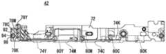
图2是表示将转印单元装设到图像形成装置的装置主体时的状况的图解图。FIG. 2 is a schematic view showing a situation when a transfer unit is mounted on the main body of the image forming apparatus.
图3是表示已除去转印皮带的状态下转印单元的前侧架周边部分的图解图。FIG. 3 is a schematic diagram showing a peripheral portion of a front side frame of the transfer unit in a state where the transfer belt has been removed.
图4是表示前侧架及配线部件的正面图。Fig. 4 is a front view showing a front side frame and a wiring member.
图5是表示前侧架及配线部件的背面图。Fig. 5 is a rear view showing a front side frame and a wiring member.
图6是表示前侧架及配线部件的底面图。Fig. 6 is a bottom view showing a front side frame and a wiring member.
图7是表示前侧架及配线部件的一端部的图解图。Fig. 7 is a schematic view showing a front side frame and one end of a wiring member.
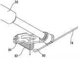
图8是表示配线部件与转印辊的连接部分的图解图。FIG. 8 is a schematic view showing a connection portion between a wiring member and a transfer roller.
图9是表示配线部件与主体侧接点端子的连接部分的图解图。FIG. 9 is a schematic view showing a connection portion between a wiring member and a main body side contact terminal.
图10是表示本发明的第2实施例的转印单元所具有的前侧架及配线部件的一端部的图解图。10 is a diagrammatic view showing a front side frame and one end portion of a wiring member included in the transfer unit according to the second embodiment of the present invention.
具体实施方式Detailed ways
[第1实施例][first embodiment]
参照图1,本发明的一实施例即图像形成装置10具有装置主体12及可装卸地装设于装置主体12的转印单元42,并以电子照片的形式在纸张(记录介质)上形成彩色图像或黑白图像。详情如下文所述,转印单元42具有与YMCK这4色对应的4个转印辊58,这4个转印辊58由设于装置主体12的高压基板经由配线部件74供电。Referring to Fig. 1, an embodiment of the present invention, that is, an
首先,对于图像形成装置10的结构进行概略性说明。另外,该第1实施例中,将与操作图像形成装置10的用户的站立位置相向的面、也就是操作面板所在之侧的面称为前表面(正面),以此规定图像形成装置10及其结构部件的前后方向(进深方向)。而且,图像形成装置10及其结构部件的左右方向(横向)是以用户观察图像形成装置10的状态为基准而规定的。First, the configuration of the
如图1所示,图像形成装置10是具有复印功能、打印功能、扫描功能及传真功能等的彩色复合机,且包含具有图像形成部30的装置主体12、及配置在装置主体12上方的图像读取装置14。其中,图像形成装置10也可为复印机、传真及打印机等中的任一种、或由其中的至少两者组合而成的复合机。As shown in FIG. 1 , an
图像读取装置14具有由透明材形成的原稿载置台16。在原稿载置台16上方,利用铰链等安装着可自由开闭的原稿按压盖18。在该原稿按压盖18的上表面设着原稿供给托盘20,在其内部设着ADF(原稿自动送给装置)。ADF自动将原稿供给托盘20内载置的原稿逐张地供给到图像读取位置22,并将其排出到原稿排出托盘24。The
而且,图像读取装置14中内置的图像读取部26具有光源、多个反射镜、成像透镜及线性传感器等。图像读取部26利用光源对原稿表面进行曝光,将经原稿表面反射的反射光通过多个反射镜导向成像透镜。并且,利用成像透镜使反射光在线性传感器的受光元件上成像。线性传感器中,检测出成像在受光元件上的反射光的亮度、色度,生成基于原稿表面的图像而成的图像数据。作为线性传感器,可采用CCD(Charge Coupled Device,电荷耦合器件)或CIS(Contact Image Sensor,接触式传感器件)等。Furthermore, the
在图像读取装置14的前表面侧设有操作面板(未图示)供接受用户所作的印刷指示等输入操作。操作面板具有附触控面板的显示器及多个操作按钮等。An operation panel (not shown) is provided on the front side of the
而且,装置主体12中,设有包括CPU、存储器等的控制部(未图示)、及图像形成部30。控制部根据对于操作面板的输入操作等,向图像形成装置10的各部位发送控制信号,并使图像形成装置10执行各种动作。Furthermore, a control unit (not shown) including a CPU, a memory, and the like, and an
图像形成部30具有曝光单元32、显影器34、感光鼓36、清洁单元38、带电器40、转印单元(中间转印单元)42、2次转印辊44及定影单元46等,在由供纸匣48等搬送的纸张上形成图像,将已形成图像的纸张排出到出纸托盘50。作为用于在纸张上形成图像的图像数据,可使用由图像读取部26读取的图像数据、或由外部计算机发送的图像数据等。The
图像形成装置10中处理的图像数据与黑色(K)、青色(C)、品红(M)及黄色(Y)这4色的彩色图像相应。因此,显影器34、感光鼓36、清洁单元38及带电器40各自设有4个以分别形成与各色相应的4种潜影,它们构成了4个图像站。4个图像站沿着转印皮带52的表面的移行方向(环绕移动方向)并排配置成1列,从转印皮带52的移行方向的下游侧起、也就是靠近2次转印辊44之侧起,按照黑色用、青色用、品红用及黄色用的顺序依次配置。而且,各色的配置顺序可适当变更。The image data processed in the
另外,附加在符号之后的标注字符K、C、M及Y用来表示是针对哪种颜色而设的要素,标注字符K、C、M及Y分别表示黑色、青色、品红及黄色。而且,在各部位的说明中,若非特别须要区分用的是哪种颜色,则省略标注字符K、C、M及Y而笼统地说明。In addition, the notation characters K, C, M, and Y added after the symbol are used to indicate which color element is provided, and the notation characters K, C, M, and Y represent black, cyan, magenta, and yellow, respectively. In addition, in the description of each part, unless it is particularly necessary to distinguish which color is used, the notation characters K, C, M, and Y will be omitted, and the description will be generalized.
感光鼓36是在具有导电性的圆筒状基体的表面形成有感光层的图像载体,其旋转轴以沿装置主体12的前后方向延伸的方式配置。带电器40使该感光鼓36的表面带有规定电位。而且,曝光单元32构成为具有激光出射部及反射镜等的激光扫描单元(LSU),通过使带电的感光鼓36的表面曝光而使与图像数据相应的静电潜影形成在感光鼓36的表面。显影器34利用4色(YMCK)的墨粉来使形成在感光鼓36表面上的静电潜影显影。而且,清洁单元38除去显影及图像转印后残留在感光鼓36表面上的墨粉。The
转印单元42具有转印皮带(中间转印皮带)52、驱动辊54、从动辊56及与4色对应的4个转印辊(中间转印辊)58等,且配置在感光鼓36上方。The
转印皮带52是具有挠性的环状皮带,由驱动辊54及从动辊56等多个辊张设,并配置成其表面(外周面)抵接于感光鼓36的表面。并且,转印皮带52伴随着驱动辊54的旋转驱动而向规定方向环绕移动。The
转印辊58隔着转印皮带52而配置在与各感光鼓36相向的各个位置上。即,4个转印辊58沿着转印皮带52的移行方向并排配置,各转印辊58的旋转轴以沿装置主体12的前后方向延伸的方式配置。当形成图像时,通过对转印辊58施加规定电压,而使感光鼓36与转印皮带52之间形成转印电场。并且,利用该转印电场的作用,使各感光鼓36的外周面上所形成的墨粉图像依序转印到环绕移动的转印皮带52的外周面。The
这种转印单元42可从装置主体12的前表面上所形成的开口部60(参照图2)可装卸地装设于转印单元收容部。详情如下文所述,当转印单元42已装设于装置主体12时,设于转印单元42的与4色对应的4个单元侧接点端子(输入端子)78分别与设于装置主体12的4个主体侧接点端子(输出端子)70电连接。Such a
2次转印辊44以推挤转印皮带52的方式设于驱动辊54附近。当形成图像时,通过对2次转印辊44施加规定电压,在转印皮带52与2次转印辊44之间形成转印电场。并且,利用该转印电场的作用,在纸张经过转印皮带52与2次转印辊44之间的转印夹持部期间,使转印皮带52的外周面上形成的墨粉图像转印到纸张。The secondary transfer roller 44 is provided near the driving
定影单元46具有加热辊及加压辊,且配置在2次转印辊44上方。加热辊设定为规定的定影温度,通过使纸张经过加热辊与加压辊之间的夹持区域,而使已转印到纸张上的墨粉图像融化、混合及压接,从而使墨粉图像热定影在纸张上。The fixing unit 46 has a heating roller and a pressure roller, and is disposed above the secondary transfer roller 44 . The heating roller is set to a specified fixing temperature, and the toner image transferred to the paper is melted, mixed and pressed by passing the paper through the nip area between the heating roller and the pressure roller, thereby making the toner The image is thermally fused to the paper.
而且,在装置主体12内,设有用于将从供纸匣48等搬送的纸张经过定位辊64、2次转印辊44及定影单元46传送到出纸托盘50的第1纸张搬送路L1。而且,形成有第2纸张搬送路L2,该第2纸张搬送路L2当对纸张进行双面印刷时,将已结束单面印刷并经过定影单元46后的纸张在2次转印辊44的纸张搬送方向的上游侧返回到第1纸张搬送路L1。在该第1纸张搬送路L1及第2纸张搬送路L2上,适当设有用于辅助性地对纸张施加推动力的多个搬送辊66。Further, in the apparatus
而且,在装置主体12的左侧部,可装卸地设有基板单元62。基板单元62具有未图示的高压基板及收容其的壳体。高压基板由商用电源供电,而将带电、显影及转印时所需的规定电压输出到各部位。该第1实施例中,高压基板具有用于向4个转印辊58分别施加规定电压的4个输出端子(未图示),这4个输出端子经由配线部件而与4个主体侧接点端子70分别电连接。Furthermore, a
另外,向彩色用转印辊58Y、M、C施加电压的高压基板的3个输出端子是从同一变压器并列分支而成,高压基板对各个彩色用转印辊58Y、M、C施加被控制为恒定电压的电压。另一方面,黑色用转印辊58K单独连接于別变压器,高压基板对黑色用转印辊58K施加被控制为恒定电流的电压。In addition, the three output terminals of the high-voltage substrates that apply voltages to the
接着,参照图2~图9,对于用于将设于装置主体12的主体侧接点端子70与转印辊58电连接的配线构造进行说明。Next, a wiring structure for electrically connecting the main body
如图2所示,具有高压基板的基板单元62装设于装置主体12的左侧部。而且,与高压基板相连的4个主体侧接点端子70全部设于装置主体12的前表面侧左端部(开口部60的左侧缘部),且从上侧起按照YMCK的顺序沿上下方呈直线状并排露出。主体侧接点端子70具有可在轴向上伸缩的螺旋压缩弹簧部,且以其前端部向前方突出的方式可伸缩地保持在有底圆筒状的端子保持部88(参照图9)内。该主体侧接点端子70与单元侧接点端子78接触时,螺旋压缩弹簧部在轴向上受到压缩,由此,对单元侧接点端子78产生施力。As shown in FIG. 2 , a
如图3~图7所示,转印单元42具有包含黑色用转印辊58K及彩色用转印辊58Y、M、C的4个转印辊58。这些转印辊58的前端部由前侧架72支撑,后端部由未图示的后侧架支撑。前侧架72及后侧架由具有电绝缘性的合成树脂形成,支撑4个转印辊58,且这4个转印辊58可旋转且移位。As shown in FIGS. 3 to 7 , the
并且,该第1实施例中,连接各个主体侧接点端子70与各个转印辊58的4个配线部件74全部配设于转印单元42的前侧架72。即,第1实施例中,支撑多个转印辊58的一端部的合成树脂制的转印架是前侧架72,该前侧架72上形成有分别保持4个配线部件74的配线保持部76(参照图7)。Furthermore, in the first embodiment, all four
各个配线部件74是通过对具有导电性的1根线材进行变形加工而形成。作为线材,可使用不锈钢丝、硬钢丝、钢琴线、及油回火线等弹簧钢丝材。Each wiring
在各配线部件74的一端部形成有单元侧接点端子78,当转印单元42装设于装置主体12时,该单元侧接点端子78抵接于对应的主体侧接点端子70。各单元侧接点端子78形成为U字状,且全部配置在前侧架72的一端部。具体而言,各单元侧接点端子78以分别与4个主体侧接点端子70对应的方式配置在前侧架72的背面侧左端部,且从上侧起按照YMCK的顺序沿上下方呈直线状并排露出。A unit-
而且,各配线部件74从前侧架72的一端部(单元侧接点端子78)延伸到对应的转印辊58附近的位置。并且,根据图8可知,各配线部件74的另一端部(转接端子80)形成为U字状,经由转接弹簧82及导电臂84等转接部件连接于转印辊58的轴。Further, each wiring
并且,该第1实施例中,3个彩色用配线部件74Y、M、C主要并列配设于前侧架72的底面。具体而言,彩色用配线部件74Y、M、C从前侧架72的配置在背面侧左端部的一端部向右斜下方延伸并绕到前侧架72的底面侧,直接通过前侧架72的底面侧而延伸到对应的彩色用转印辊58Y、M、C附近的位置。并且,之后,另一端部绕到前侧架72的背面侧而与转接弹簧82电连接。Furthermore, in the first embodiment, the three
另一方面,黑色用配线部件74K主要配设于前侧架72的前表面。具体而言,从前侧架72的配置在背面侧左端部的一端部绕到前侧架72的前表面侧,且直接通过前侧架72的前表面侧而延伸到超过彩色用转印辊58M的位置。并且,之后,绕到前侧架72的背面侧而延伸到黑色用转印辊58K附近的位置,且另一端部与转接弹簧82电连接。On the other hand, the
这种转印单元42中,与装置主体12相比,前侧架72上没有怎么设置其他高压零件及接地零件。即,前侧架72上的配线路径的限制少,能相对自由地配设配线部件74。因此,通过像该第1实施例那样在前侧架72上配设配线部件74,能使配线路径缩短,也容易确保配线部件74彼此的沿面距离及空间距离。In such a
而且,通过在前侧架72上配设配线部件74,能针对各色使配线部件74的另一端部(转接端子80)与转印辊58的位置关系成为同相位。因此,能针对各色使转接弹簧82及导电臂84等转接部件共通,所以能降低部件成本。Furthermore, by arranging the
另外,将单元侧接点端子78全部配置在前侧架72的一端部,并将与它们对应的4个主体侧接点端子70全部配置在高压基板附近,由此,能使装置主体12的配线路径缩短且简化。即,也能以节省空间的方式低成本地进行装置主体12侧的配线。In addition, all the unit-
而且,将彩色用配线部件74Y、M、C分别配设在前侧架72的底面,将黑色用配线部件74K配设在前侧架72的前表面,即,使彩色用配线部件74Y、M、C与黑色用配线部件74K之间隔着转印架72的树脂壁,从而,能确保它们之间具有恰当的沿面距离。因此,能恰当地防止彩色用配线部件74Y、M、C与黑色用配线部件74K之间的短路。而且,通过在空间有裕度的前侧架72的底面上邻近地配设彩色用配线部件74Y、M、C,也容易确保与其他接地连接零件的沿面距离。Moreover, the
返回到图4~图7,该第1实施例中,在前侧架72上的至少并列配设有彩色用配线部件74Y、M、C的部分,在彩色用配线部件74Y、M、C之间形成有肋部(隔壁)86。即,该第1实施例中,在因电位相同所以无需较大沿面距离的彩色用配线部件74Y、M、C之间,也能通过形成肋部86而更切实地防止彩色用配线部件74Y、M、C间的短路。Returning to FIGS. 4 to 7, in the first embodiment, at least the
而且,在前侧架72的背面侧左端部,形成有从单元侧接点端子78的周缘部向后方突出的大致圆筒状的突出部90。如图9所示,当转印单元42装设在装置主体12时,该突出部90与装置主体12上所形成的端子保持部88重叠,而包围端子保持部88的前端部。由此,能恰当确保各色的主体侧接点端子70与单元侧接点端子78的接点彼此的沿面距离,并切实地防止相邻的接点间的短路。Further, a substantially cylindrical protruding
另外,在前侧架72的左端部(具体而言为单元侧接点端子78的配置位置的左邻),定位孔92与供紧固螺钉94安装的螺钉安装孔96沿上下方向并排形成。定位孔92是通过与装置主体12上形成的未图示的定位轮毂相嵌合而使转印单元42相对于装置主体12定位的部位(定位部)。并且,也可在前侧架72侧形成定位轮毂。而且,紧固螺钉94是用于使转印单元42相对于装置主体12固定的固定部件。In addition, at the left end portion of the front side frame 72 (specifically, on the left side where the unit-
这样,通过将4色的主体侧接点端子70及单元侧接点端子78集中配置在靠近定位轮毂及定位孔92的位置,能使各接点端子彼此的位置关系稳定。而且,通过将4色的主体侧接点端子70及单元侧接点端子78集中配置在靠近紧固螺钉94的位置,能使前侧架72抵抗因主体侧接点端子70的加压造成的弯曲等,从而能使转印单元42保持稳定的姿势。In this way, by arranging the body-
如以上所述,根据该第1实施例,能通过将彩色用配线部件74Y、M、C与黑色用配线部件74K配置在前侧架72的不同面这样的简单结构来确保彩色用配线部件74Y、M、C与黑色用配线部件74K的沿面距离及空间距离,从而能恰当地防止配线部件74彼此短路。As described above, according to the first embodiment, it is possible to secure the
而且,根据该第1实施例,将多个配线部件74配设于前侧架72,且将单元侧接点端子78全部配置在前侧架72的一端部,因此,能使转印单元42的配线路径缩短,也容易确保配线部件74彼此的沿面距离及空间距离。而且,还能使装置主体12的配线路径缩短且简化,能以节省空间的方式低成本地进行装置主体12侧的配线。另外,能针对各色使配线部件74的另一端部与转印辊58的位置关系成为同相位,使各色的转接部件共通,因此能降低部件成本。Moreover, according to the first embodiment, a plurality of
[第2实施例][Second embodiment]
接着,参照图10,对本发明的第2实施例即转印单元42进行说明。该第2实施例中,供彩色用配线部件74Y、M、C及黑色用配线部件74K配设的前侧架72的面不同于所述第1实施例。除此以外均与第1实施例相同,因此省略重复说明。另一实施例中,也同样省略重复说明。Next, referring to FIG. 10 , a
如图10所示,该第2实施例中,3个彩色用配线部件74Y、M、C皆主要配设于前侧架72的前表面。另一方面,黑色用配线部件74K主要配设于前侧架72的底面。而且,单元侧接点端子78从上侧起按照KCMY的顺序沿上下方向呈直线状并排配置在前侧架72的背面侧左端部。As shown in FIG. 10 , in the second embodiment, all three
该第2实施例中,也具有与第1实施例相同的作用效果,能确保彩色用配线部件74Y、M、C与黑色用配线部件74K之间具有恰当的沿面距离,从而能恰当地防止彩色用配线部件74Y、M、C与黑色用配线部件74K之间的短路。This second embodiment also has the same effects as those of the first embodiment, and it is possible to secure an appropriate creepage distance between the
[第3实施例][third embodiment]
虽省略图示,但第3实施例中,3个彩色用配线部件74Y、M、C皆主要配设于前侧架72的底面。另一方面,黑色用配线部件74K主要配设于前侧架72的上表面。而且,各单元侧接点端子78从上侧起按照KCMY的顺序沿上下方向呈直线状并排配置在前侧架72的背面侧左端部。Although not shown, in the third embodiment, the three
根据该第3实施例,能确保彩色用配线部件74Y、M、C与黑色用配线部件74K之间具有恰当的沿面距离,从而能恰当地防止彩色用配线部件74Y、M、C与黑色用配线部件74K之间的短路。According to this third embodiment, an appropriate creepage distance can be ensured between the
[第4实施例][Fourth embodiment]
虽省略图示,但第4实施例中,3个彩色用配线部件74Y、M、C皆主要配设于前侧架72的前表面。另一方面,黑色用配线部件74K主要配设于前侧架72的上表面。而且,各单元侧接点端子78从上侧起按照KCMY的顺序沿上下方向呈直线状并排配置在前侧架72的背面侧左端部。Although not shown, in the fourth embodiment, the three
该第4实施例中,也具有与第3实施例相同的作用效果,能确保彩色用配线部件74Y、M、C与黑色用配线部件74K之间具有恰当的沿面距离,从而能恰当地防止彩色用配线部件74Y、M、C与黑色用配线部件74K之间的短路。This fourth embodiment also has the same function and effect as that of the third embodiment, and it is possible to secure an appropriate creepage distance between the
另外,所述各实施例中,将各配线部件74配设于前侧架72,但也可将各配线部件74配设于后侧架。也就是说,本发明的支撑多个转印辊58的一端部的合成树脂制的转印架也可为后侧架。当将各配线部件74配设于后侧架时,也将各单元侧接点端子78全部配置在后侧架的一端部,且将彩色用配线部件74Y、M、C与黑色用配线部件74K配置在后侧架的不同面上。例如彩色用配线部件74Y、M、C配设于主要后侧架的底面,黑色用配线部件74K配设于主要后侧架的背面。In addition, in each of the above-described embodiments, each wiring
与装置主体12相比,后侧架上没怎么设置另一高压零件及接地零件。因此,通过在后侧架上配设配线部件74,能与前侧架72同样地使配线路径缩短,从而也容易确保配线部件74彼此的沿面距离及空间距离。而且,若考虑到主体侧接点端子70与单元侧接点端子78的定位的容易度等,优选将各配线部件74配设于前侧架72。Compared with the device
另外,上文所列举的具体的数值及零件形状等皆仅为一例,可根据产品的规格等适当变更。In addition, the specific numerical values and component shapes listed above are merely examples, and may be appropriately changed according to product specifications and the like.
附图标记说明Explanation of reference signs
10 图像形成装置10 image forming device
12 装置主体12 Device body
14 图像读取装置14 Image reading device
30 图像形成部30 Image Formation Department
42 转印单元42 transfer unit
62 基板单元62 base units
70 主体侧接点端子70 Body side contact terminal
72 前侧架(转印架)72 Front frame (transfer frame)
74 配线部件74 Wiring parts
78 单元侧接点端子78 Unit side contact terminals
Claims (7)
Translated fromChineseApplications Claiming Priority (2)
| Application Number | Priority Date | Filing Date | Title |
|---|---|---|---|
| JP2019078378AJP7265920B2 (en) | 2019-04-17 | 2019-04-17 | Transfer unit and image forming device |
| JP2019-078378 | 2019-04-17 |
Publications (2)
| Publication Number | Publication Date |
|---|---|
| CN111830808A CN111830808A (en) | 2020-10-27 |
| CN111830808Btrue CN111830808B (en) | 2022-11-29 |
Family
ID=72832335
Family Applications (1)
| Application Number | Title | Priority Date | Filing Date |
|---|---|---|---|
| CN202010269254.9AActiveCN111830808B (en) | 2019-04-17 | 2020-04-08 | Transfer unit and image forming device |
Country Status (3)
| Country | Link |
|---|---|
| US (1) | US11061358B2 (en) |
| JP (1) | JP7265920B2 (en) |
| CN (1) | CN111830808B (en) |
Citations (4)
| Publication number | Priority date | Publication date | Assignee | Title |
|---|---|---|---|---|
| JP2005114793A (en)* | 2003-10-03 | 2005-04-28 | Ricoh Co Ltd | Power feeding face plate and image forming apparatus |
| CN102073251A (en)* | 2009-11-19 | 2011-05-25 | 富士施乐株式会社 | Feeding apparatus and image forming apparatus |
| CN102269951A (en)* | 2010-06-07 | 2011-12-07 | 京瓷美达株式会社 | Imaging forming apparatus with high-voltage broad |
| CN103838116A (en)* | 2012-11-26 | 2014-06-04 | 京瓷办公信息系统株式会社 | Transfer device and image forming apparatus including same |
Family Cites Families (9)
| Publication number | Priority date | Publication date | Assignee | Title |
|---|---|---|---|---|
| JP3820840B2 (en)* | 2000-03-14 | 2006-09-13 | コニカミノルタビジネステクノロジーズ株式会社 | Image forming apparatus |
| JP4413725B2 (en)* | 2004-09-22 | 2010-02-10 | シャープ株式会社 | Transfer belt device and image forming apparatus |
| JP5282464B2 (en)* | 2008-07-11 | 2013-09-04 | 株式会社リコー | Transfer unit and image forming apparatus |
| JP5606398B2 (en)* | 2010-06-07 | 2014-10-15 | 京セラドキュメントソリューションズ株式会社 | Image forming apparatus |
| JP5315309B2 (en)* | 2010-08-26 | 2013-10-16 | 京セラドキュメントソリューションズ株式会社 | Image forming apparatus |
| JP5831250B2 (en)* | 2012-01-23 | 2015-12-09 | ブラザー工業株式会社 | Electrode for image forming apparatus and image forming apparatus |
| JP6217583B2 (en)* | 2014-10-16 | 2017-10-25 | 京セラドキュメントソリューションズ株式会社 | Image forming apparatus |
| JPWO2016067841A1 (en)* | 2014-10-31 | 2017-06-01 | 京セラドキュメントソリューションズ株式会社 | Image forming apparatus |
| JP6361608B2 (en)* | 2015-08-28 | 2018-07-25 | 京セラドキュメントソリューションズ株式会社 | Image forming apparatus |
- 2019
- 2019-04-17JPJP2019078378Apatent/JP7265920B2/enactiveActive
- 2020
- 2020-04-03USUS16/840,219patent/US11061358B2/enactiveActive
- 2020-04-08CNCN202010269254.9Apatent/CN111830808B/enactiveActive
Patent Citations (4)
| Publication number | Priority date | Publication date | Assignee | Title |
|---|---|---|---|---|
| JP2005114793A (en)* | 2003-10-03 | 2005-04-28 | Ricoh Co Ltd | Power feeding face plate and image forming apparatus |
| CN102073251A (en)* | 2009-11-19 | 2011-05-25 | 富士施乐株式会社 | Feeding apparatus and image forming apparatus |
| CN102269951A (en)* | 2010-06-07 | 2011-12-07 | 京瓷美达株式会社 | Imaging forming apparatus with high-voltage broad |
| CN103838116A (en)* | 2012-11-26 | 2014-06-04 | 京瓷办公信息系统株式会社 | Transfer device and image forming apparatus including same |
Also Published As
| Publication number | Publication date |
|---|---|
| US20200333743A1 (en) | 2020-10-22 |
| CN111830808A (en) | 2020-10-27 |
| JP2020177100A (en) | 2020-10-29 |
| US11061358B2 (en) | 2021-07-13 |
| JP7265920B2 (en) | 2023-04-27 |
Similar Documents
| Publication | Publication Date | Title |
|---|---|---|
| US7978997B2 (en) | Developer cartridges, process cartridges, and image formation devices | |
| JP6198495B2 (en) | Image forming apparatus | |
| US9188933B2 (en) | Power supply device and image forming apparatus | |
| JP2004157463A (en) | Image forming device | |
| CN110764380B (en) | Image forming apparatus and voltage supply method | |
| US8810833B2 (en) | Image processing device and image forming apparatus | |
| JP2011133773A (en) | Exposure device and image forming device | |
| US10108125B2 (en) | Image forming apparatus | |
| JP2011203677A (en) | Image forming apparatus | |
| US9031456B2 (en) | Image forming apparatus, detachable unit, and plural detachable units | |
| US20220260936A1 (en) | Image forming apparatus | |
| JP5934668B2 (en) | Image forming apparatus | |
| CN111830808B (en) | Transfer unit and image forming device | |
| JP4760365B2 (en) | Image forming apparatus | |
| JP2010078721A (en) | Image forming cartridge and image forming apparatus | |
| CN110018622B (en) | Electric connection structure and image forming apparatus | |
| JP2005283848A (en) | Charger and image forming apparatus | |
| US9170538B2 (en) | Electronic device | |
| JP2012118277A (en) | Image forming apparatus | |
| JP5738152B2 (en) | Image forming apparatus | |
| JP7278869B2 (en) | Electrical relay device and image forming device | |
| JP6521142B2 (en) | Image forming device | |
| US20190354065A1 (en) | Developing device and image forming apparatus including the same | |
| JP2016161906A (en) | Image formation device | |
| CN111381476A (en) | Image forming apparatus with a toner supply device |
Legal Events
| Date | Code | Title | Description |
|---|---|---|---|
| PB01 | Publication | ||
| PB01 | Publication | ||
| SE01 | Entry into force of request for substantive examination | ||
| SE01 | Entry into force of request for substantive examination | ||
| GR01 | Patent grant | ||
| GR01 | Patent grant |