CN111823280A - A robot collision reminder device - Google Patents
A robot collision reminder deviceDownload PDFInfo
- Publication number
- CN111823280A CN111823280ACN202010430848.3ACN202010430848ACN111823280ACN 111823280 ACN111823280 ACN 111823280ACN 202010430848 ACN202010430848 ACN 202010430848ACN 111823280 ACN111823280 ACN 111823280A
- Authority
- CN
- China
- Prior art keywords
- frame
- collision
- pressing plate
- warning
- prompting device
- Prior art date
- Legal status (The legal status is an assumption and is not a legal conclusion. Google has not performed a legal analysis and makes no representation as to the accuracy of the status listed.)
- Granted
Links
Images


Classifications
- B—PERFORMING OPERATIONS; TRANSPORTING
- B25—HAND TOOLS; PORTABLE POWER-DRIVEN TOOLS; MANIPULATORS
- B25J—MANIPULATORS; CHAMBERS PROVIDED WITH MANIPULATION DEVICES
- B25J19/00—Accessories fitted to manipulators, e.g. for monitoring, for viewing; Safety devices combined with or specially adapted for use in connection with manipulators
- B25J19/06—Safety devices
- B—PERFORMING OPERATIONS; TRANSPORTING
- B25—HAND TOOLS; PORTABLE POWER-DRIVEN TOOLS; MANIPULATORS
- B25J—MANIPULATORS; CHAMBERS PROVIDED WITH MANIPULATION DEVICES
- B25J9/00—Programme-controlled manipulators
- B25J9/16—Programme controls
- B25J9/1674—Programme controls characterised by safety, monitoring, diagnostic
- B25J9/1676—Avoiding collision or forbidden zones
Landscapes
- Engineering & Computer Science (AREA)
- Robotics (AREA)
- Mechanical Engineering (AREA)
- Manipulator (AREA)
Abstract
Translated fromChinese
Description
Translated fromChinese技术领域technical field
本发明涉及机械手生产制造技术领域,特别涉及一种机械手碰撞提示装置。The invention relates to the technical field of manipulator production and manufacturing, in particular to a manipulator collision prompting device.
背景技术Background technique
在工业自动化生产中,机械手的应用比较普遍,机械手一种能模仿人手和臂的某些动作功能,用以按固定程序抓取、搬运物件或操作工具的自动操作装置。特点是可以通过编程来完成各种预期的作业,构造和性能上兼有人和机械手机器各自的优点。然而快速运行的机械手具有较强的动能,由于高速运动,稍微有一点的位置变化就会引起剧烈的碰撞,也常常导致机械部件之间发生碰撞,机械手与物件的长期碰撞容易导致机械损,降低产品品质,甚至损坏物品,因此需要对伸缩和上下升降运动的机械手进行结构优化,避免机械手运动时产生的碰撞进而保证产品的生产质量。In industrial automation production, the application of manipulator is relatively common. Manipulator is an automatic operation device that can imitate some action functions of human hands and arms to grab, carry objects or operate tools according to fixed procedures. The feature is that it can be programmed to complete a variety of expected operations, and the structure and performance have the advantages of both human and robotic machines. However, fast-running manipulators have strong kinetic energy. Due to high-speed motion, a slight position change will cause violent collisions, and often lead to collisions between mechanical parts. Long-term collisions between manipulators and objects can easily lead to mechanical damage. Therefore, it is necessary to optimize the structure of the manipulator for telescopic and up and down movements to avoid collisions caused by the movement of the manipulator and to ensure the production quality of products.
中国专利号CN201720651104.8公开了一种龙门式机械手防撞保护装置,包括设于机械手纵轴梁上的垂向滑动机构、与所述滑动机构对应的防撞检测单元以及与所述防撞检测单元连接的控制器,所述垂向滑动机构与工件抓取单元连接,所述控制器与机械手电源开关连接。当机械手纵轴下行且工件抓取单元与机床夹具发生干涉时,垂向滑动机构带动工件抓取单元向上运动并脱离防撞检测单元的检测范围,此时控制器将会切断机械手的电源开关,避免工件抓取单元与机床发生碰撞而受损,即该装置仅能在垂直方向上实现防撞,对其他方向的可能碰撞无法起到警示作用,其次,仅能对单一程度的碰撞干涉起到防撞作用,无法根据碰撞的剧烈程度进行分级警示。Chinese Patent No. CN201720651104.8 discloses a gantry-type manipulator anti-collision protection device, which includes a vertical sliding mechanism arranged on the longitudinal beam of the manipulator, an anti-collision detection unit corresponding to the sliding mechanism, and an anti-collision detection unit corresponding to the sliding mechanism. The unit is connected to the controller, the vertical sliding mechanism is connected to the workpiece grabbing unit, and the controller is connected to the power switch of the manipulator. When the longitudinal axis of the manipulator goes down and the workpiece grabbing unit interferes with the machine tool fixture, the vertical sliding mechanism drives the workpiece grabbing unit to move upward and leave the detection range of the anti-collision detection unit. At this time, the controller will cut off the power switch of the manipulator. Avoid the collision between the workpiece grabbing unit and the machine tool and damage, that is, the device can only achieve anti-collision in the vertical direction, and cannot serve as a warning to possible collisions in other directions. Secondly, it can only play a role in a single degree of collision interference. The anti-collision effect cannot be classified according to the severity of the collision.
发明内容SUMMARY OF THE INVENTION
针对以上现有技术的不足,本发明的目的在于提供一种机械手碰撞提示装置,通过按压板移动不同距离后,分别按压不同的接触开关,进而启动不同的警示装置,可有效达到分级触碰警示的效果,能够预防快速运动中的机械碰撞,对机械手起到保护作用。In view of the above deficiencies of the prior art, the purpose of the present invention is to provide a collision reminder device for a manipulator, which can effectively achieve graded touch warning by pressing different contact switches after moving different distances by the pressing plate, and then activating different warning devices. It can prevent mechanical collisions in fast motion and protect the manipulator.
为实现上述目的,本发明具体通过以下技术实现:To achieve the above object, the present invention is specifically realized through the following technologies:
一种机械手碰撞提示装置,包括机架和设于支撑机构内的防撞组件,所述防撞组件包括支撑板、与所述支撑板顶部固接的滑杆以及固设于所述支撑板边缘的按压板,所述滑杆顶端位于所述机架内且与所述机架滑移配合,所述滑杆外侧套设有弹簧,且所述弹簧的两端分别与所述机架和支撑板相抵接,所述机架上与所述按压板对应位置设有多个接触开关,多个所述接触开关分别连接对应状态的警示装置,根据所述按压板触碰接触开关来控制警示装置予以分级警示。A collision prompting device for a manipulator, comprising a frame and an anti-collision assembly arranged in a support mechanism, the anti-collision assembly comprising a support plate, a sliding rod fixed to the top of the support plate, and a sliding rod fixed to the edge of the support plate The top end of the sliding rod is located in the frame and is slidingly matched with the frame, the outer side of the sliding rod is sleeved with a spring, and the two ends of the spring are respectively connected with the frame and the support The plates are in contact with each other, a plurality of contact switches are arranged on the frame corresponding to the pressing plates, and the plurality of contact switches are respectively connected to the warning devices in corresponding states, and the warning devices are controlled according to the pressing plates touching the contact switches. be graded warning.
采用上述的技术方案:将外部的动力负载连接在防撞组件的支撑板底部,机械手则通过安装板连接在机架一侧;动力负载带动支撑板向上移动,支撑板同步带动与之固接的按压板向上移动,依次接触多个接触开关,即多个所述接触开关先后与所述按压板接触,而每个接触开关分别电连接对应的警示装置,警示装置包括但不限于指示灯和蜂鸣器等;以下以不同颜色的指示灯为例进行说明,所述警示装置可包括绿色电源指示灯、黄色预警指示灯和红色警报指示灯。具体为:本装置开始工作时,点亮绿色电源指示灯;而当本装置遭到轻度碰撞时,支撑板移动较小距离,首先接触黄色预警指示灯对应的接触开关,点亮黄色预警指示灯,当遭到重度碰撞时,支撑板移动较大距离,接触红色警报指示灯对应的接触开关,点亮红色警报指示灯,达到分级触碰警示的效果,有效防止快速运动中的机械碰撞,进而对机械手起到保护作用。在外力碰撞过程中,按压板上移的同时会挤压弹簧,此时弹簧储存弹性势能,当外力碰撞消失后,弹簧释放弹性势能,恢复形变,并带动防撞组件复位。The above technical solution is adopted: the external power load is connected to the bottom of the support plate of the anti-collision component, and the manipulator is connected to one side of the frame through the mounting plate; the power load drives the support plate to move upward, and the support plate synchronously drives the fixed-connected The pressing plate moves upwards and contacts a plurality of contact switches in turn, that is, a plurality of the contact switches are in contact with the pressing plate successively, and each contact switch is electrically connected to a corresponding warning device, which includes but is not limited to an indicator light and a beeper. buzzer, etc.; the following takes the indicator lights of different colors as an example for description, and the warning device may include a green power indicator light, a yellow warning indicator light and a red warning indicator light. Specifically: when the device starts to work, the green power indicator is lit; and when the device is slightly collided, the support plate moves a small distance, first touches the contact switch corresponding to the yellow warning indicator, and lights up the yellow warning indicator When a heavy collision occurs, the support plate moves a large distance, contacts the contact switch corresponding to the red alarm indicator light, and lights the red alarm indicator light to achieve the effect of graded touch warning and effectively prevent mechanical collisions in rapid motion. This in turn protects the manipulator. During the collision of external force, when the pressing plate moves, it will squeeze the spring. At this time, the spring stores elastic potential energy. When the external force collision disappears, the spring releases the elastic potential energy, restores the deformation, and drives the anti-collision component to reset.
进一步的,所述按压板顶部朝向所述接触开关的一侧具有倾斜面,所述倾斜面与所述接触开关的接触点相切。斜面具有导向作用,有利于按压板更灵敏的按压接触开关。Further, a side of the top of the pressing plate facing the contact switch has an inclined surface, and the inclined surface is tangent to the contact point of the contact switch. The inclined surface has a guiding function, which is beneficial to the more sensitive pressing of the pressing plate and the contact switch.
进一步的,多个所述接触开关并列竖直分布,所述按压板具有一个倾斜面。通过并列设置,多个所述接触开关离所述倾斜面的距离不同,而按压板的移动距离与碰撞力度相关,因此,通过按压板移动的距离不同,分别启动不同的警示装置,实现分级触碰警示。Further, a plurality of the contact switches are arranged in parallel and vertically, and the pressing plate has an inclined surface. By arranging side by side, the distances of a plurality of the contact switches from the inclined surface are different, and the moving distance of the pressing plate is related to the collision force. Therefore, different warning devices are activated according to the different moving distances of the pressing plate, so as to realize the step-by-step contact. Touch warning.
进一步的,多个所述接触开关并排水平分布,所述按压板具有多个倾斜面,多个所述倾斜面的斜率不同。通过多个水平分布且斜率不同的倾斜面,使得不同列设置的接触开关和倾斜面之间的距离不相同,即,不同斜率的倾斜面按压与之同一列的接触开关所需的移动行程不同,因此,通过按压板移动的距离不同,分别启动不同的警示装置,实现分级触碰警示。Further, a plurality of the contact switches are horizontally distributed side by side, the pressing plate has a plurality of inclined surfaces, and the slopes of the plurality of inclined surfaces are different. Through multiple horizontally distributed inclined surfaces with different slopes, the distances between the contact switches arranged in different columns and the inclined surfaces are different, that is, the moving strokes required by the inclined surfaces with different slopes to press the contact switches in the same column are different. , therefore, different warning devices are activated by the different moving distances of the pressing plate, so as to realize a graded touch warning.
进一步的,所述机架上纵向延伸有限位杆,所述支撑板与所述限位杆滑动连接。通过限位杆在限位槽内的导向限位作用,使支撑板只能沿其轴向垂直移动,防止支撑板作大角度的相对转动,提高其按压接触开关的灵敏性。Further, a limit rod extends longitudinally on the frame, and the support plate is slidably connected to the limit rod. Through the guiding and limiting action of the limit rod in the limit groove, the support plate can only move vertically along its axial direction, preventing the support plate from rotating relative to a large angle, and improving the sensitivity of the contact switch.
进一步的,所述机架的下面板与所述支撑板之间搁置有呈T字形的活动板,所述活动板下端贯穿所述机架底部且可相对所述机架转动,所述活动板下端连接动力负载。Further, a T-shaped movable plate is placed between the lower panel of the rack and the support plate, the lower end of the movable plate penetrates through the bottom of the rack and can be rotated relative to the rack, and the movable plate The lower end is connected to the power load.
采用上述的技术方案:活动板的转动或垂直偏转或上下移动都将引起其上方的支撑板的位移发生变化,因此,添加活动板可将动力负载受到的任何方向的外界碰撞和转矩负载都转换为单一方向的行程—支撑板的上下垂直移动,从而提高防撞效果,防撞灵敏度高,大大提高了机械手的安全性能。Using the above technical solution: the rotation or vertical deflection or up and down movement of the movable plate will cause the displacement of the support plate above it to change. Therefore, adding the movable plate can reduce the external impact and torque load of the dynamic load in any direction. Converted to a single-direction stroke—the up and down vertical movement of the support plate, so as to improve the anti-collision effect, the anti-collision sensitivity is high, and the safety performance of the manipulator is greatly improved.
进一步的,所述机架的下面板上成型有扇形凹槽,所述活动板底部成型有与所述凹槽形状相适配的扇形凸起,且所述扇形凸起的面积小于所述扇形凹槽的面积。通过扇形凹槽限定所述扇形凸起的转动角度,从而防止活动板限对所述机架过度偏转,引起动力负载负荷过大,起到保护动力负载的作用。Further, a fan-shaped groove is formed on the lower panel of the frame, and a fan-shaped protrusion matching the shape of the groove is formed at the bottom of the movable plate, and the area of the fan-shaped protrusion is smaller than that of the fan-shaped protrusion. area of the groove. The rotation angle of the fan-shaped protrusion is limited by the fan-shaped groove, so as to prevent the movable plate from over-deflecting the frame, causing excessive dynamic load, and protecting the dynamic load.
进一步的,所述机架的下面板与所述活动板之间设有多个滚珠。设置滚珠可保证活动板平滑复位。Further, a plurality of balls are arranged between the lower panel of the frame and the movable panel. Setting the ball can ensure the smooth return of the movable plate.
本发明的有益效果是:The beneficial effects of the present invention are:
1、本发明通过按压板移动不同距离后,分别按压不同的接触开关,进而启动不同的警示装置,可有效达到分级触碰警示的效果,能够预防快速运动中的机械碰撞,对机械手起到保护作用。1. In the present invention, after the pressing plate moves different distances, different contact switches are pressed respectively, and then different warning devices are activated, which can effectively achieve the effect of graded touch warning, can prevent mechanical collisions in rapid movement, and protect the manipulator. effect.
2、通过活动板将动力负载受到的外界无方向的碰撞和转矩负载转化为支撑板的上下垂直移动,防撞灵敏度高,大大提高了机械手的安全性能。2. The non-directional impact and torque load received by the power load from the outside are converted into the vertical vertical movement of the support plate through the movable plate, and the anti-collision sensitivity is high, which greatly improves the safety performance of the manipulator.
附图说明Description of drawings
为了更清楚地说明本发明实施例中的技术方案,下面将对实施例描述中所需要使用的附图作简单地介绍,显而易见地,下面描述中的附图仅仅是本发明的一些实施例,对于本领域普通技术人员来讲,在不付出创造性劳动的前提下,还可以根据这些附图获得其他的附图。In order to illustrate the technical solutions in the embodiments of the present invention more clearly, the following briefly introduces the accompanying drawings used in the description of the embodiments. Obviously, the accompanying drawings in the following description are only some embodiments of the present invention. For those of ordinary skill in the art, other drawings can also be obtained from these drawings without creative effort.
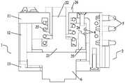
图1是实施例1的机械手碰撞提示装置的结构示意图;1 is a schematic structural diagram of a manipulator collision prompting device according to Embodiment 1;
图2是实施例2的机械手碰撞提示装置的结构示意图;2 is a schematic structural diagram of a manipulator collision prompting device according to Embodiment 2;
图3是实施例2的机械手碰撞提示装置(无接触开关部分)的立体图;3 is a perspective view of the manipulator collision prompting device (contactless switch part) of Embodiment 2;
图4是图3的右视图;Fig. 4 is the right side view of Fig. 3;
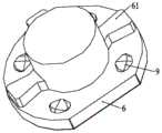
图5是实施例2的活动板的立体图;Fig. 5 is the perspective view of the movable plate of embodiment 2;
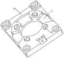
图6是实施例2的下面板的立体图;6 is a perspective view of the lower panel of Embodiment 2;
图7是实施例3的机械手碰撞提示装置的结构示意图;FIG. 7 is a schematic structural diagram of the manipulator collision prompting device of Embodiment 3;
图中,1、机架;11、上面板;12、固定柱;13、下面板;2、防撞组件;21、支撑板;22、滑杆;23、按压板;24、倾斜面;241、第一倾斜面;242、第二倾斜面;25、弹簧;26、导套;3、限位杆;4、接触开关;5、警示装置;6、活动板;61、扇形凸起;7、扇形凹槽;8、滚珠;9、滚珠槽。In the figure, 1, frame; 11, upper panel; 12, fixed column; 13, lower panel; 2, anti-collision component; 21, support plate; 22, sliding rod; 23, pressing plate; 24, inclined surface; 241 , the first inclined surface; 242, the second inclined surface; 25, the spring; 26, the guide sleeve; 3, the limit rod; 4, the contact switch; 5, the warning device; 6, the movable plate; , sector groove; 8, ball; 9, ball groove.
具体实施方式Detailed ways
下面将结合本发明实施例中的附图,对实施例中的技术方案进行清楚、完整地描述。显然,所描述的实施例仅仅是本发明的一部分实施例,而不是全部的实施例。基于本发明的实施例,本领域普通技术人员在没有作出创造性劳动前提下所获得的所有其他实施例,都属于本发明保护的范围。The technical solutions in the embodiments will be clearly and completely described below with reference to the accompanying drawings in the embodiments of the present invention. Obviously, the described embodiments are only some, but not all, embodiments of the present invention. Based on the embodiments of the present invention, all other embodiments obtained by persons of ordinary skill in the art without creative efforts shall fall within the protection scope of the present invention.
实施例1Example 1
一种机械手碰撞提示装置,参见图1,包括机架1和设于支撑机构内的防撞组件2,所述机架1包括上面板11、下面板13和设于上、下面板13之间的固定柱12,所述固定柱12用于固定连接上、下面板13,形成矩形框架,所述防撞组件2设于矩形框架围成的空腔内,所述防撞组件2包括支撑板21、与所述支撑板21顶部固接的滑杆22以及固设于所述支撑板21边缘的按压板23,所述滑杆22顶端位于所述机架1内且与所述机架1滑移配合,所述滑杆22外侧套设有弹簧25,且所述弹簧25的两端分别与所述机架1和支撑板21相抵接,具体的,所述上面板11的中心设有通孔,所述通孔内安装有导套26,所述导套26的高度与所述滑杆22长度一致;所述滑杆22顶端伸入所述导套26内并可沿所述导套26上下移动,所述支撑板21的横截面积大于所述滑杆22的横截面积,且所述支撑板21顶部和所述上面板11底部均开设有容置弹簧25的弹簧槽,所述弹簧25上下端放置在弹簧槽内,当所述滑杆22在外力作用下向上移动时,所述弹簧25压缩,储存弹性势能,当外力移除,所述弹簧25伸缩,释放弹性势能,使防撞组件2复位;为了提高滑杆22滑动的平稳性,所述机架1上纵向延伸有限位杆3(见图3),所述支撑板21与所述限位杆3滑动连接,具体的,所述支撑板21的边缘设有限位槽,所述限位杆3的底部容置于所述限位槽内,通过限位杆3在限位槽内的导向限位作用,使支撑板21只能垂直移动。所述按压板23顶部具有倾斜面24,所述机架1上对应所述倾斜面24的位置处设有多个接触开关4,多个所述接触开关4分别连接对应状态的警示装置5,所述倾斜面24与所述接触开关4的接触点相切,根据所述按压板23触碰接触开关4来控制警示装置5予以分级警示。A manipulator collision prompting device, see FIG. 1 , includes a frame 1 and an anti-collision assembly 2 arranged in a support mechanism, the frame 1 includes an
本实施例中,多个所述接触开关4并排水平分布,此时,所述按压板23具有多个倾斜面24,多个所述倾斜面24的斜率不同。本实施例以2个倾斜面24和警示装置5为指示灯为例进行说明,第一倾斜面241和第二倾斜面242并排设置,且第一倾斜面241的斜率小于第二倾斜面242的斜率,第一倾斜面241对应的接触开关4和第二倾斜面242对应的接触开关4分别连接黄色预警指示灯和红色警报指示灯。在支撑板21移动过程中,第一倾斜面241和第二倾斜面242依次按压与黄色预警指示灯和红色警报指示灯连接的接触开关4。In this embodiment, a plurality of the contact switches 4 are distributed horizontally side by side, and at this time, the
采用上述的技术方案:将外部的动力负载(图中未示出)连接在防撞组件2的支撑板21底部,机械手则通过安装板连接在机架1一侧;本装置正常工作时,绿色电源指示灯亮;而当动力负载遭到外力碰撞引发支撑板21位移变化时,支撑板21位移变化距离的大小与碰撞力度相关。轻度碰撞时,支撑板21移动距离较小,带动按压板23移动较小距离,此时,第一倾斜面241按压与黄色预警指示灯连接的接触开关4,黄色预警指示灯亮;重度碰撞时,支撑板21移动距离较大,带动按压板23移动较大距离,第二倾斜面242按压与红色警报指示灯连接的接触开关4,红色警报指示灯亮,从而可以实现两级触碰警示。上述的两级触碰方式仅为示例性结构,并不应作为对本发明保护范围的限定,本领域技术人员应该知道,任何只要能够实现多个所述接触开关4依次与所述倾斜面24接触的设置方式都属于本发明的保护范围,如还可以设置为三级触碰、四级触碰或者更多。The above technical solution is adopted: the external dynamic load (not shown in the figure) is connected to the bottom of the
实施例2Example 2
实施例2与实施例1基本相同,其区别在于:参见图2~6,所述机架1的下面板13与所述支撑板21之间搁置有呈T字形的活动板6,所述活动板6下端贯穿所述机架1底部且可相对所述机架1转动,所述活动板6下端连接动力负载。即,所述活动板6位于所述支撑板21的下方,且搁置在所述下面板13上,所述活动板6的下端伸出所述下面板13且与所述下面板13转动连接,因此,所述活动板6可相对所述下面板13和所述支撑板21上下移动和垂直偏转。为了防止活动板6过度偏转,所述机架1的下面板13上成型有扇形凹槽7,所述活动板6底部成型有与所述凹槽形状相适配的扇形凸起61,且所述扇形凸起61的面积小于所述扇形凹槽7的面积,以此通过形凹槽限定所述扇形凸起61的转动角度,优选所述扇形凸起61为3个,相对的所述扇形凹槽7也为3个,即所述活动板6其中一侧为设置所述扇形凸起61,且为设置所述扇形凸起61的一侧设置有切口,方便接触开关固定板的安装。The second embodiment is basically the same as the first embodiment, the difference is: referring to FIGS. 2 to 6 , a T-shaped
进一步优选的,所述机架1的下面板13与所述活动板6之间设有多个滚珠8。具体的,所述下面板13与所述活动板6对应位置均设有滚珠8槽,防止滚珠8滚出。设置滚珠8可保证活动板6平滑复位。Further preferably, a plurality of balls 8 are arranged between the
采用上述的技术方案:通过活动板6将动力负载受到的外界碰撞和转矩负载转化为支撑板21的上下垂直移动,防撞灵敏度高,大大提高了机械手的安全性能。The above technical solution is adopted: the external impact and torque load received by the power load are converted into the vertical vertical movement of the
实施例3Example 3
实施例3与实施例1或实施例2基本相同,其区别在于:参见图7,多个所述接触开关4并列竖直分布,此时,所述按压板23可只具有一个倾斜面24。通过并列设置,多个所述接触开关4离所述倾斜面24的距离不同,而按压板23的移动距离与碰撞力度相关,因此,通过按压板23移动的距离不同,分别启动不同的警示装置5,实现分级触碰警示。Embodiment 3 is basically the same as Embodiment 1 or Embodiment 2, with the difference that: referring to FIG. 7 , a plurality of the contact switches 4 are arranged vertically side by side, and at this time, the
Claims (8)
Translated fromChinesePriority Applications (1)
| Application Number | Priority Date | Filing Date | Title |
|---|---|---|---|
| CN202010430848.3ACN111823280B (en) | 2020-05-20 | 2020-05-20 | A robot collision reminder device |
Applications Claiming Priority (1)
| Application Number | Priority Date | Filing Date | Title |
|---|---|---|---|
| CN202010430848.3ACN111823280B (en) | 2020-05-20 | 2020-05-20 | A robot collision reminder device |
Publications (2)
| Publication Number | Publication Date |
|---|---|
| CN111823280Atrue CN111823280A (en) | 2020-10-27 |
| CN111823280B CN111823280B (en) | 2022-04-19 |
Family
ID=72913720
Family Applications (1)
| Application Number | Title | Priority Date | Filing Date |
|---|---|---|---|
| CN202010430848.3AActiveCN111823280B (en) | 2020-05-20 | 2020-05-20 | A robot collision reminder device |
Country Status (1)
| Country | Link |
|---|---|
| CN (1) | CN111823280B (en) |
Citations (11)
| Publication number | Priority date | Publication date | Assignee | Title |
|---|---|---|---|---|
| US4573271A (en)* | 1984-03-14 | 1986-03-04 | General Motors Corporation | Machine performance sensor |
| US6346751B1 (en)* | 2000-02-14 | 2002-02-12 | Ocim, S.R.L. | Safety tool mount for robotic apparatus |
| CN201264146Y (en)* | 2008-10-16 | 2009-07-01 | 北京林克曼数控技术股份有限公司 | Cutting torch anticollision device |
| CN202641661U (en)* | 2012-04-12 | 2013-01-02 | 三一重工股份有限公司 | Anti-tipping device and engineering machine |
| CN202778864U (en)* | 2012-08-30 | 2013-03-13 | 中国第一汽车股份有限公司 | Anti-collision device for robot automatic adhesive dispensing device |
| CN203541876U (en)* | 2013-10-16 | 2014-04-16 | 丽水学院 | Three-degree-of-freedom anti-collision force sensor |
| CN106736120A (en)* | 2017-01-10 | 2017-05-31 | 江苏昌弘机器人科技有限公司 | Anticollision sensor and welding robot |
| CN206415785U (en)* | 2017-01-10 | 2017-08-18 | 江苏昌弘机器人科技有限公司 | Anticollision sensor, anti-collision protective device and welding robot |
| CN207027557U (en)* | 2017-06-06 | 2018-02-23 | 上汽通用五菱汽车股份有限公司 | A kind of gantry-type mechanical arm anti-collision protection device |
| CN209764043U (en)* | 2019-05-28 | 2019-12-10 | 江门市英合创展电子有限公司 | Displacement sensor |
| CN210100059U (en)* | 2019-04-04 | 2020-02-21 | 苏州镒升机器人科技有限公司 | Manipulator anticollision warning device |
- 2020
- 2020-05-20CNCN202010430848.3Apatent/CN111823280B/enactiveActive
Patent Citations (11)
| Publication number | Priority date | Publication date | Assignee | Title |
|---|---|---|---|---|
| US4573271A (en)* | 1984-03-14 | 1986-03-04 | General Motors Corporation | Machine performance sensor |
| US6346751B1 (en)* | 2000-02-14 | 2002-02-12 | Ocim, S.R.L. | Safety tool mount for robotic apparatus |
| CN201264146Y (en)* | 2008-10-16 | 2009-07-01 | 北京林克曼数控技术股份有限公司 | Cutting torch anticollision device |
| CN202641661U (en)* | 2012-04-12 | 2013-01-02 | 三一重工股份有限公司 | Anti-tipping device and engineering machine |
| CN202778864U (en)* | 2012-08-30 | 2013-03-13 | 中国第一汽车股份有限公司 | Anti-collision device for robot automatic adhesive dispensing device |
| CN203541876U (en)* | 2013-10-16 | 2014-04-16 | 丽水学院 | Three-degree-of-freedom anti-collision force sensor |
| CN106736120A (en)* | 2017-01-10 | 2017-05-31 | 江苏昌弘机器人科技有限公司 | Anticollision sensor and welding robot |
| CN206415785U (en)* | 2017-01-10 | 2017-08-18 | 江苏昌弘机器人科技有限公司 | Anticollision sensor, anti-collision protective device and welding robot |
| CN207027557U (en)* | 2017-06-06 | 2018-02-23 | 上汽通用五菱汽车股份有限公司 | A kind of gantry-type mechanical arm anti-collision protection device |
| CN210100059U (en)* | 2019-04-04 | 2020-02-21 | 苏州镒升机器人科技有限公司 | Manipulator anticollision warning device |
| CN209764043U (en)* | 2019-05-28 | 2019-12-10 | 江门市英合创展电子有限公司 | Displacement sensor |
Also Published As
| Publication number | Publication date |
|---|---|
| CN111823280B (en) | 2022-04-19 |
Similar Documents
| Publication | Publication Date | Title |
|---|---|---|
| CN118976992B (en) | Anti-collision multi-axis welding robot with weld joint tracking function | |
| CN111823280B (en) | A robot collision reminder device | |
| CN219173680U (en) | Stacking manipulator with lifting and translation functions | |
| CN108436979B (en) | Free-moving type robot anti-collision base and anti-collision method thereof | |
| CN209504168U (en) | A kind of anticollision device, collision-prevention device and mobile platform of mobile platform | |
| CN117686357A (en) | Performance detection device for heavy goods shelf beam | |
| CN207205903U (en) | A kind of positioner of workpiece | |
| CN212527802U (en) | Industrial robot anticollision constructional device | |
| CN212355607U (en) | Material taking assembly | |
| CN111360880A (en) | Manipulator anticollision protection device | |
| CN208020207U (en) | Cylinder type safety keystroke system | |
| CN111409151B (en) | Top block of laminating machine top plate system | |
| CN107814172B (en) | Centrifugal mechanism is prevented in realization upset | |
| CN112141553A (en) | Material storage device, material conveying equipment and control method of material conveying equipment | |
| CN110026805B (en) | Numerical control machine tool with safety limiting mechanism | |
| CN212894501U (en) | Hidden grating mounting structure | |
| CN221539859U (en) | Anticollision device and industrial robot equipment | |
| CN222409915U (en) | A PCM board positioning device | |
| CN217728725U (en) | Full protection type robot walking track | |
| CN221069106U (en) | Electronic price tag anti-collision box | |
| CN213277891U (en) | Box transformer door plate travel switch device | |
| CN204171785U (en) | Crossbeam impact protection apparatus | |
| CN221160357U (en) | Plane manipulator protection mechanism | |
| CN209022117U (en) | A kind of multidirectional anticollision automatic runback device | |
| CN219169398U (en) | Locking mechanism for profiling rod of off-line profiling device of stamping die |
Legal Events
| Date | Code | Title | Description |
|---|---|---|---|
| PB01 | Publication | ||
| PB01 | Publication | ||
| SE01 | Entry into force of request for substantive examination | ||
| SE01 | Entry into force of request for substantive examination | ||
| GR01 | Patent grant | ||
| GR01 | Patent grant | ||
| CP03 | Change of name, title or address | ||
| CP03 | Change of name, title or address | Address after:430000 East Lake New Technology Development Zone, Wuhan City, Hubei Province, 818 High-tech Avenue, No. 4, 4th Floor, 7th Building, B District, High-tech Medical Device Park Patentee after:Wuhan Zilian Hongkang Technology Co.,Ltd. Country or region after:China Address before:430000 East Lake New Technology Development Zone, Wuhan City, Hubei Province, 818 High-tech Avenue, No. 4, 4th Floor, 7th Building, B District, High-tech Medical Device Park Patentee before:WUHAN ZNION TECHNOLOGY Co.,Ltd. Country or region before:China | |
| TR01 | Transfer of patent right | ||
| TR01 | Transfer of patent right | Effective date of registration:20250310 Address after:No.16, Fenghuangyuan Middle Road, Donghu New Technology Development Zone, Wuhan, Hubei 430000 Patentee after:WUHAN YIRUIDE MEDICAL EQUIPMENT Co.,Ltd. Country or region after:China Address before:430000 East Lake New Technology Development Zone, Wuhan City, Hubei Province, 818 High-tech Avenue, No. 4, 4th Floor, 7th Building, B District, High-tech Medical Device Park Patentee before:Wuhan Zilian Hongkang Technology Co.,Ltd. Country or region before:China |