CN111821539A - An infusion port for hemodialysis - Google Patents
An infusion port for hemodialysisDownload PDFInfo
- Publication number
- CN111821539A CN111821539ACN202010694504.3ACN202010694504ACN111821539ACN 111821539 ACN111821539 ACN 111821539ACN 202010694504 ACN202010694504 ACN 202010694504ACN 111821539 ACN111821539 ACN 111821539A
- Authority
- CN
- China
- Prior art keywords
- infusion port
- liquid storage
- storage tank
- support
- support part
- Prior art date
- Legal status (The legal status is an assumption and is not a legal conclusion. Google has not performed a legal analysis and makes no representation as to the accuracy of the status listed.)
- Granted
Links
Images


Classifications
- A—HUMAN NECESSITIES
- A61—MEDICAL OR VETERINARY SCIENCE; HYGIENE
- A61M—DEVICES FOR INTRODUCING MEDIA INTO, OR ONTO, THE BODY; DEVICES FOR TRANSDUCING BODY MEDIA OR FOR TAKING MEDIA FROM THE BODY; DEVICES FOR PRODUCING OR ENDING SLEEP OR STUPOR
- A61M5/00—Devices for bringing media into the body in a subcutaneous, intra-vascular or intramuscular way; Accessories therefor, e.g. filling or cleaning devices, arm-rests
- A61M5/14—Infusion devices, e.g. infusing by gravity; Blood infusion; Accessories therefor
- A61M5/158—Needles for infusions; Accessories therefor, e.g. for inserting infusion needles, or for holding them on the body
- A61M2005/1587—Needles for infusions; Accessories therefor, e.g. for inserting infusion needles, or for holding them on the body suitable for being connected to an infusion line after insertion into a patient
Landscapes
- Health & Medical Sciences (AREA)
- Vascular Medicine (AREA)
- Engineering & Computer Science (AREA)
- Anesthesiology (AREA)
- Biomedical Technology (AREA)
- Heart & Thoracic Surgery (AREA)
- Hematology (AREA)
- Life Sciences & Earth Sciences (AREA)
- Animal Behavior & Ethology (AREA)
- General Health & Medical Sciences (AREA)
- Public Health (AREA)
- Veterinary Medicine (AREA)
- Infusion, Injection, And Reservoir Apparatuses (AREA)
Abstract
Translated fromChinese
Description
Translated fromChinese技术领域technical field
本发明涉及一种医疗辅助设备,具体为一种血液透析用输液港。The invention relates to a medical auxiliary device, in particular to an infusion port for hemodialysis.
背景技术Background technique
血液透析是指将体内的血液引流至体外,血液在体外经过透析机将血液中的代谢废物清除后,又重新回输至体内的过程。血液透析一般主要是针对肾功能衰竭病人的一种替代治疗方式。由于人体随时都在产生代谢废物,而血液透析的病人需要依靠血液透析来清除这些代谢废物,所以血液透析的病人需要长期并多频次的进行血液透析治疗。血液透析时的血液引流至体外和血液的回输都是直接与血管连通来实现的。如果每次血液透析时都采用直接刺穿血管的方式来与血管连通,由于血液透析的次数较多,频繁的刺穿血管容易引发血管的病变,增加病人的痛苦。为了减少刺穿血管的次数,可以采用在体内植入与血管保持连通的输液港的方式。Hemodialysis refers to the process of draining the blood from the body to the outside of the body. Hemodialysis is generally an alternative treatment for patients with renal failure. Because the human body produces metabolic wastes at any time, and hemodialysis patients need to rely on hemodialysis to remove these metabolic wastes, so hemodialysis patients need long-term and frequent hemodialysis treatment. During hemodialysis, the drainage of blood to the body and the return of blood are achieved by direct communication with blood vessels. If the blood vessel is directly punctured to communicate with the blood vessel every time during hemodialysis, due to the large number of hemodialysis times, frequent puncturing of the blood vessel is likely to cause vascular lesions and increase the pain of the patient. In order to reduce the number of times of puncturing the blood vessel, an infusion port that is kept in communication with the blood vessel can be implanted in the body.
现有的输液港包括输液港座单元、穿刺隔膜和导管,输液港座单元上设置有储液槽,穿刺隔膜覆盖在储液槽的开口处,导管的一端与储液槽连通,导管的另一端设置有带有三向瓣膜阀的开口并与血管连通,从而使输液港座单元的储液槽通过导管可以与血管连通。血液透析时,通过使用无损伤针穿过穿刺隔膜并与储液槽连通就可以实现与血管的连通,从而减少了穿刺血管的次数,减少了引发血管病变的风险。输液港的使用是需要通过手术植入人体内的,而现有的输液港的输液港座单元的体积较大,于是在植入时需要切开较大的切口,既形成了较大的创面,又延长了植入手术的时间,不利于病人快速的恢复。The existing infusion port includes an infusion port base unit, a puncture diaphragm and a catheter. The infusion port base unit is provided with a liquid storage tank, the puncture diaphragm covers the opening of the liquid storage tank, one end of the catheter is communicated with the liquid storage tank, and the other side of the catheter is connected to the liquid storage tank. One end is provided with an opening with a three-way valve valve and communicates with the blood vessel, so that the liquid storage tank of the infusion port base unit can be communicated with the blood vessel through the catheter. During hemodialysis, the communication with the blood vessel can be achieved by using an atraumatic needle to pass through the puncture diaphragm and communicate with the reservoir, thereby reducing the number of blood vessel punctures and reducing the risk of vascular lesions. The use of the infusion port needs to be implanted into the human body through surgery, and the volume of the infusion port base unit of the existing infusion port is relatively large, so a larger incision needs to be cut during implantation, which not only forms a larger wound surface , and prolongs the time of implantation operation, which is not conducive to the rapid recovery of patients.
发明内容SUMMARY OF THE INVENTION
本发明的目的在于提供一种植入时手术切口小的血液透析用输液港。The purpose of the present invention is to provide an infusion port for hemodialysis with a small surgical incision during implantation.
为了解决上述问题,本发明的基础方案为:一种血液透析用输液港,包括两个并排设置的输液港座单元,所述输液港座单元的内部设有储液槽,输液港座单元上密封连接有覆盖在储液槽开口处的穿刺隔膜,每个所述输液港座单元上均连接有与储液槽连通的导管,所述输液港座单元包括支撑部和调节部,调节部与支撑部螺纹连接,所述穿刺隔膜与调节部连接。In order to solve the above problems, the basic solution of the present invention is: an infusion port for hemodialysis, comprising two infusion port base units arranged side by side, the interior of the infusion port base unit is provided with a liquid storage tank, and the infusion port base unit is provided with a liquid storage tank. A puncture diaphragm covering the opening of the liquid storage tank is sealed and connected, and each of the infusion port base units is connected with a conduit communicating with the liquid storage tank. The infusion port base unit includes a support part and an adjustment part, and the adjustment part is connected with The support part is screwed, and the puncture diaphragm is connected with the adjustment part.
与现有技术相比,本发明的优点在于:输液港座单元在未植入人体之前,调节部与支撑部在螺纹的作用下相互配合比较紧凑,使储液槽的体积被尽可能的压缩,从而使整个输液港座单元的体积较小,于是,在进行植入人体手术时,手术的切口可以比较小就能实现放置输液港座单元的要求,从而可以减轻病人的痛苦、节约手术时间、缩短手术恢复的时间。Compared with the prior art, the advantages of the present invention are: before the infusion port base unit is implanted into the human body, the adjustment part and the support part cooperate with each other more compactly under the action of the thread, so that the volume of the liquid storage tank is compressed as much as possible. , so that the volume of the entire infusion port base unit is small, so that when the human body is implanted, the incision of the operation can be relatively small to meet the requirements of placing the infusion port base unit, thereby reducing the pain of the patient and saving the operation time. , shorten the recovery time of surgery.
进一步,所述支撑部上沿储液槽的周向设置有外螺纹段,所述调节部上设置有与外螺纹段螺纹配合的内螺纹段;所述外螺纹段的螺距大于螺纹牙底部的宽度,外螺纹段的螺纹牙朝向调节部的一侧设置有若干缺口,内螺纹段的螺纹牙朝向支撑部的一侧设置有若干与缺口凹凸配合的凸起。Further, the support portion is provided with an external thread segment along the circumference of the liquid storage tank, and the adjustment portion is provided with an internal thread segment that is threadedly matched with the external thread segment; the pitch of the external thread segment is greater than that of the thread bottom. The thread teeth of the external thread segment are provided with a number of notches on the side facing the adjustment part, and the thread teeth of the inner thread segment are provided with a number of protrusions matching the concave-convex grooves on the side of the inner thread segment.
采用螺距大于螺纹牙的宽度的设置方式,使外螺纹段与内螺纹段之间可以在不相对转动的情况下沿轴线方向上进行小距离的相对滑动,从而来实现控制缺口与凸起之间的相连或分离,当缺口与凸起相互连接的时候,内螺纹段与外螺纹段之间由于缺口与凸起的作用而不能相对转动,从而实现外螺纹段与内螺纹段之间的相互锁止作用;当凸起与缺口处于分离状态时,外螺纹段与内螺纹段可以进行相对转动,从而实现调节整个输液港座单元的体积的目的。The pitch is greater than the width of the thread, so that the external thread segment and the internal thread segment can slide relative to each other along the axis direction for a small distance without relative rotation, so as to control the gap between the notch and the protrusion. When the gap and the protrusion are connected to each other, the internal thread segment and the external thread segment cannot rotate relative to each other due to the effect of the gap and the protrusion, so as to realize the mutual locking between the external thread segment and the internal thread segment. When the protrusion and the notch are in a separated state, the external thread segment and the internal thread segment can rotate relative to each other, so as to achieve the purpose of adjusting the volume of the entire infusion port base unit.
具体在使用中时,输液港座单元位于人体的皮肤与肌肉之间,输液港座单元的支撑部是位于靠近肌肉一侧的位置,而调节部是位于靠近皮肤一侧的位置,从而使皮肤产生的弹力将调节部往支撑部的一侧挤压,从而使内螺纹段与外螺纹段之间的缺口和凸起实现连接配合,进而增强了内螺纹段与外螺纹段之间的锁止作用,避免了调节部与支撑部之间发生相对转动而导致输液港座单元的体积随意发生变化的情况发生,即输液港座单元内的储液槽的深度处于一个固定值的状态,避免由于输液港的体积变化而导致储液槽的深度与记录的深度不同,进而避免了无损伤针的规格的选择与储液槽的深度不匹配而带来的使用问题的发生。Specifically in use, the infusion port unit is located between the skin and the muscle of the human body, the support part of the infusion port unit is located on the side close to the muscle, and the adjustment part is located on the side close to the skin, so that the skin The generated elastic force squeezes the adjusting part to one side of the supporting part, so that the gaps and protrusions between the internal thread segment and the external thread segment are connected and matched, thereby enhancing the locking between the internal thread segment and the external thread segment It can avoid the situation that the volume of the infusion port base unit changes at will due to the relative rotation between the adjustment part and the support part, that is, the depth of the liquid storage tank in the infusion port base unit is in a state of a fixed value. The volume change of the infusion port causes the depth of the liquid storage tank to be different from the recorded depth, thereby avoiding the occurrence of use problems caused by the incompatibility of the specification of the non-destructive needle with the depth of the liquid storage tank.
进一步,所述穿刺隔膜上固设有朝向储液槽延伸的延长段,所述延长段与支撑部密封滑动配合。延长段的设置,可以使整个穿刺隔膜在厚度满足穿刺要求的情况使,延长段伸入储液槽内而充分的利用储液槽的空间来放置穿刺隔膜,从而减小穿刺隔膜与储液槽所占的空间,有利于进一步减小输液港座单元在植入人体之前的体积,进而方便输液港座单元的植入操作。Further, an extension section extending toward the liquid storage tank is fixed on the puncture diaphragm, and the extension section is in sealing and sliding fit with the support portion. The arrangement of the extension section can make the entire puncture diaphragm meet the puncture requirements. The extension section extends into the liquid storage tank and fully utilizes the space of the liquid storage tank to place the puncture diaphragm, thereby reducing the size of the puncture diaphragm and the liquid storage tank. The space occupied is beneficial to further reduce the volume of the infusion port base unit before being implanted into the human body, thereby facilitating the implantation operation of the infusion port base unit.
进一步,所述延长段呈圆台状,并且延长段的直径较大端朝向支撑部设置。采用这样的设置方式,使支撑部对延长段产生的作用力具有将穿刺隔膜朝向支撑部的方向推动的作用,从而使穿刺隔膜带动调节部朝向支撑部挤压,辅助调节部与支撑部之间的螺纹段在缺口与凸起的作用下加强锁止作用,提高调节部与支撑部之间的位置的相对稳定。Further, the extension section is in the shape of a truncated cone, and the larger diameter end of the extension section is disposed toward the support portion. With this arrangement, the force generated by the support portion on the extension has the effect of pushing the puncture diaphragm toward the support portion, so that the puncture diaphragm drives the adjustment portion to squeeze toward the support portion, and assists the adjustment portion and the support portion between the Under the action of the notch and the protrusion, the threaded section of the threaded section strengthens the locking effect, and improves the relative stability of the position between the adjusting part and the supporting part.
进一步,所述调节部远离支撑部的一端固设有两块磁铁块,两块磁铁块沿调节部的端部对称设置,并且两块磁铁块背对支撑部的一端的磁极呈异极性设置。设置两块磁铁块,通过在人体的外部使用相应的磁铁机构就可以实现对调节部的拉动和扭转作用,方便在无损伤的情况下对调节部与支撑部之间的相对位置进行调整,提高了输液港使用的便捷性。Further, two magnet blocks are fixed at one end of the adjusting portion away from the support portion, the two magnet blocks are symmetrically arranged along the end portion of the adjusting portion, and the magnetic poles of the end of the two magnet blocks facing away from the support portion are arranged in opposite polarities. . Two magnet blocks are provided, and the adjustment part can be pulled and twisted by using the corresponding magnet mechanism outside the human body, which is convenient to adjust the relative position between the adjustment part and the support part without damage. The convenience of using the infusion port.
进一步,所述支撑部上沿储液槽内壁的周向设置有若干挡片,挡片朝向储液槽底部的一端与支撑部弹性连接,挡片背对支撑部的一侧与穿刺隔膜滑动配合,挡片与支撑部之间设置有储液袋,支撑部远离调节部的一端沿垂直于外螺纹段的轴线方向滑动连接有若干支撑块,支撑部上连接有可推动支撑块移动的驱动袋,驱动袋与储液袋连通。Further, a plurality of baffles are arranged on the support part along the circumference of the inner wall of the liquid storage tank, the end of the baffle plate facing the bottom of the liquid storage tank is elastically connected with the support part, and the side of the baffle plate facing away from the support part is slidingly matched with the puncture diaphragm. A liquid storage bag is arranged between the baffle and the support part, the end of the support part away from the adjustment part is slidably connected with a number of support blocks along the axis direction perpendicular to the external thread segment, and the support part is connected with a drive bag that can push the support block to move , the drive bag communicates with the reservoir bag.
挡片的设置,使穿刺隔膜的延长段在与支撑部相对移动时,穿刺隔膜的延长段可以推动挡片摆动,从而使挡片挤压储液袋,使储液袋内的液体流入驱动袋中。驱动袋随着液体的增多而发生膨胀,使驱动袋推动支撑块滑动,从而增大支撑部与人体的接触面积,减少压强作用,有利于提高输液港使用时的舒适性。The setting of the baffle allows the extension of the puncture diaphragm to push the baffle to swing when the extension of the puncture diaphragm moves relative to the support part, so that the baffle squeezes the liquid storage bag, so that the liquid in the liquid storage bag flows into the drive bag middle. The drive bag expands as the liquid increases, so that the drive bag pushes the support block to slide, thereby increasing the contact area between the support part and the human body, reducing the pressure effect, and improving the comfort of the infusion port.
进一步,所述调节部的外侧滑动套设有套管,套管的一端与支撑部密封固定连接,套管与调节部之间设置有单向密封膜。单向密封膜的作用是使套管外侧的空气可以顺利的进入到套管与调节部之间的缝隙处,而阻止缝隙处的空气进入到套管的外侧。通过套管的设置,使套管对支撑部上的外螺纹段进行遮挡,减少了外螺纹段由于与人体皮肤的接触面过大而发生粘连,导致取出输液港时不易操作的问题发生。同时,套管与调节部的密封配合,增强了调节部与支撑部之间的密封屏障,减少了储液槽内的血液渗透至输液港座单元外侧的情况发生。Further, the outer sliding sleeve of the adjusting part is provided with a sleeve, one end of the sleeve is sealed and fixedly connected with the support part, and a one-way sealing film is arranged between the sleeve and the adjusting part. The function of the one-way sealing film is to allow the air outside the casing to smoothly enter the gap between the casing and the adjusting part, and prevent the air at the gap from entering the outside of the casing. Through the arrangement of the sleeve, the sleeve can shield the external thread section on the support part, which reduces the adhesion of the external thread segment due to the excessive contact surface with the human skin, which leads to the problem that it is difficult to operate when taking out the infusion port. At the same time, the sealing cooperation between the sleeve and the adjusting part strengthens the sealing barrier between the adjusting part and the supporting part, and reduces the occurrence of the blood in the liquid storage tank penetrating to the outside of the infusion port unit.
进一步,所述单向密封膜与调节部固定连接,单向密封膜呈空心圆台状,单向密封膜的直径较小端朝远离储液槽底部的方向设置并与调节部固定连接,单向密封膜的直径较大端与套管滑动配合。采用这样的设置方式,使调节部朝远离支撑部的方向移动时,单向密封膜在摩擦力的作用下处于拉伸状态,从而使单向密封膜可以通过形变来减少摩擦力的作用,进而有利于提高单向密封膜的使用寿命。Further, the one-way sealing film is fixedly connected with the adjusting part, the one-way sealing film is in the shape of a hollow truncated cone, and the smaller diameter end of the one-way sealing film is set away from the bottom of the liquid storage tank and is fixedly connected with the adjusting part, and the one-way sealing film The larger diameter end of the sealing membrane is a sliding fit with the sleeve. With this arrangement, when the adjusting part moves away from the supporting part, the one-way sealing film is in a stretched state under the action of friction, so that the one-way sealing film can reduce the effect of friction through deformation, and then It is beneficial to improve the service life of the one-way sealing film.
附图说明Description of drawings
图1为本发明实施例一的结构示意图;1 is a schematic structural diagram of
图2为图1中一个输液港座单元的全剖视图;Fig. 2 is a full cross-sectional view of an infusion port base unit in Fig. 1;
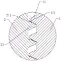
图3为图2中A处的放大图;Fig. 3 is the enlarged view of A place in Fig. 2;
图4为图2中输液港座单元的使用状态图;Fig. 4 is the use state diagram of the infusion port base unit in Fig. 2;
图5本发明实施例二中一个输液港座单元的结构示意图;5 is a schematic structural diagram of an infusion port base unit in the second embodiment of the present invention;
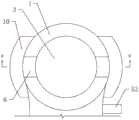
图6为本发明实施例三的结构示意图;6 is a schematic structural diagram of
图7为图6中一个输液港座单元处于使用状态时的俯视图;Fig. 7 is a top view when an infusion port base unit is in use in Fig. 6;
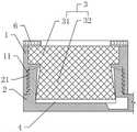
图8为图7中B-B初始状态的剖视图;Fig. 8 is the sectional view of B-B initial state in Fig. 7;
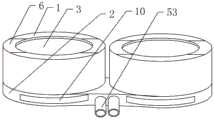
图9为本发明实施例四的结构示意图;9 is a schematic structural diagram of
图10为图9中一个输液港单元的全剖视图;Figure 10 is a full cross-sectional view of an infusion port unit in Figure 9;
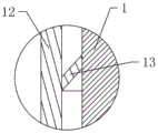
图11为图10中C处的放大图。FIG. 11 is an enlarged view of C in FIG. 10 .
具体实施方式Detailed ways
下面通过具体实施方式进一步详细说明:The following is further described in detail by specific embodiments:
说明书附图中的附图标记包括:调节部1、内螺纹段11、凸起111、支撑部2、外螺纹段21、缺口211、穿刺隔膜3、连接段31、延伸段32、储液槽4、导管5、进液口51、出液口52、连接头53、磁铁块6、挡片7、限位块71、储液袋8、驱动袋9、支撑块10、套管12、单向密封膜13。Reference numerals in the accompanying drawings include:
实施例一:基本如附图1、图2、图3和图4所示:一种血液透析用输液港,包括两个结构相同的输液港座单元,两个输液港座单元并排设置,输液港座单元包括支撑部2和调节部1;支撑部2呈圆柱状,两个输液港座单元的支撑部并排设置并形成一个整体;支撑部2上沿轴向设置有储液槽4,支撑部2侧面的底部连接有与储液槽4连通的导管5;支撑部2上沿储液槽4的周向设置有外螺纹段21,外螺纹段21的螺距大于螺纹牙底部的宽度,本实施例中螺距为螺纹牙底部的宽度的两倍;外螺纹段21的螺纹牙背对储液槽4底部的一侧设置有若干缺口211;调节部1与支撑部2同轴设置,调节部1呈圆筒状,调节部1上设置有与支撑部2的外螺纹段21螺纹配合的内螺纹段11,内螺纹段11的螺纹牙朝向储液槽4底部一侧设置有若干与缺口211凹凸配合的凸起111,由于螺距大于螺纹牙底部的宽度,使调节部1与支撑部2在不发生相对转动的情况下可以沿轴向相对滑动,从而实现缺口211与凸起111之间的连接或分离。调节部1的内部粘接有穿刺隔膜3,穿刺隔膜3沿调节部1的轴向分为连接段31和圆台状的延伸段32,连接段31与延伸段32一体成型,连接段31与调节部1粘接固定,延伸段32的直径较大端伸至储液槽4的内部并与支撑部2密封滑动配合。Embodiment 1: basically as shown in Figure 1, Figure 2, Figure 3 and Figure 4: a kind of infusion port for hemodialysis, including two infusion port base units with the same structure, two infusion port base units are arranged side by side, infusion port The port unit includes a
两个输液港座单元的支撑部2侧面的底部均固接有与各自储液槽4连通的连接头53,两个连接头53并排设置,连接头53的一端延伸至支撑部2的外侧,从而方便与导管5进行连接。导管5的内部设有两条独立的通道,导管5与两个连接头53连接时,一个通道与一个连接头53一一对应连通;导管5远离连接头53的一端设置有进液口51和出液口52,进液口51与出液口52之间间隔距离四厘米,进液口51与其中一个通道连通,出液口52与另一个通道连通,进液口51和出液口52处均设置有三向瓣膜阀;三向瓣膜阀的特点为,负压时,阀门向内打开,可抽血;正压时,阀门向外打开,可输液或输血;平衡时,阀门关闭,避免了空气栓塞、血液返流或凝固的风险,减少了封管操作的工作负担。使用时,导管5同时与两个连接头53连接固定,从而使导管5内的两个通道与两个输液港座单元一一对应连通,导管5的一端穿入静脉血管中,使出液口52位于静脉血管的近心一侧,而进液口51位于静脉血管的远心一侧。The bottoms of the side surfaces of the
具体实施过程如下:输液港座单元在未植入人体之前,调节部1与支撑部2在螺纹的作用下相互配合比较紧凑,即外螺纹段21与内螺纹段11配合的长度较长,使整个输液港座单元的体积较小,同时,穿刺隔膜3的延伸段32也处于伸入储液槽4内的状态,于是,整个输液港座单元相较与现有技术的输液港座单元的体积较小,所以在进行植入手术时可以使手术切口较小就可以实现放置输液港座单元的目的。当将输液港座单元植入人体后,固定支撑部2,然后轴向拉动调节部1,使调节部1和支撑部2之间的凸起111与缺口211分离,再然后旋转调节部1,使调节部1与支撑部2相对转动,从而使调节部1和支撑部2在外螺纹段21和内螺纹段11的作用下相互远离;同时,调节部1也带动穿刺隔膜3的延伸段32逐渐退出储液槽4,使储液槽4的实际储存空间逐渐增大;最后根据使用要求停止调节部1的旋转,并适当的沿轴向按压调节部1朝支撑部2的方向移动,使外螺纹段21上的缺口211与内螺纹段11上的凸起111配合连接,使外螺纹段21与内螺纹段11实现相互的锁止作用。随着手术切口的愈合,皮肤会施加给调节部1一个朝向支撑部2的压力,使外螺纹段21与内螺纹段11之间实现持续的锁止作用,从而避免调节部1在人体内随意发生旋转而造成储液槽4的体积发生变化的情况发生。The specific implementation process is as follows: before the infusion port base unit is not implanted into the human body, the
导管5的一端沿血液回流心脏的方向插入人体的静脉血管中,从而使进液口51位于静脉血管的远心一侧,而出液口52位于静脉血管的近心一侧,从而在进行血液透析的时候,从与进液口51连通的输液港座单元中抽取人体的血液至透析机中进行处理,而处理后的血液又从与出液口52连通的输液港座单元注入人体中,从而实现血液的透析操作。One end of the
实施例二:与实施例一的区别点仅在于:如图5所示,调节部1远离支撑部2的一端固定嵌设有两块磁铁块6,两块磁铁块6沿调节部1的端部对称设置,并且两块磁铁块6背对支撑部2的一端的磁极的极性为异极性。设置两块磁铁块6,通过在人体的外部使用相应的磁铁机构就可以实现对调节部1的拉动和扭转作用,方便在无损伤的情况下对调节部1与支撑部2之间的相对位置进行调整,提高了输液港使用的便捷性。尤其是针对一些透析病人由于身体功能的下降,导致体重在短时间内发生较大的变化,使皮肤变的松弛,从而使原本输液港座单元的体积容易在身体内移动,不利于输液港座单元与导管5之间的连接处保持稳定性,通过在皮肤的外侧使用磁铁来转动调节部1,使输液港座单元的体积增大,以填充皮肤松弛所造成的输液港座单元放置处的多余空间,从而使输液港座单元又持续的受到皮肤的压力作用而不易发生移动的问题,提高了输液港座单元使用的可靠性。Embodiment 2: The only difference from
实施例三:与实施例二的区别点仅在于:如图6、图7和图8所示,支撑部2上沿储液槽4内壁的周向设置有若干挡片7,所有挡片7沿支撑部2的轴向呈环形阵列分布,挡片7的下端与支撑部2弹性连接,挡片7背对支撑部2的一侧与穿刺隔膜3滑动配合;挡片7的上端背对支撑部2轴线的一侧一体成型有横向的限位块71,挡片7与支撑部2之间设置有储液袋8,限位块71可以限制储液袋8向上发生形变而脱离挡片7与支撑部2之间的空隙;所有挡片7在弹力作用下其上端相互靠近支撑部2的轴线,从而使所有挡片7围成一个近似的空心圆台结构;支撑部2远离调节部1的一端沿垂直于外螺纹段21的轴线方向滑动连接有若干支撑块10,本实施例中每个输液港座单元的支撑部2上设置的支撑块10的数量为两块,并且两块支撑块10对称设置;支撑部2的底部沿径向设置有滑槽,每块支撑块10位于对应的滑槽内并与支撑部2滑动配合;支撑部2的底部的中部粘接固定有驱动袋9,驱动袋9为弹性材料制成,支撑块10朝向支撑部2中部的一端与驱动袋9相抵,从而通过驱动袋9的体积膨胀可以推动支撑块10进行滑动;驱动袋9与储液袋8连通,具体为在支撑部2上开设连通储液袋8与驱动袋9的通道。Embodiment 3: The only difference from
当调节部1与支撑部2相互移动时,调节部1带动穿刺隔膜3的延长段与支撑部2相对移动,穿刺隔膜3的延长段推动挡片7往远离支撑部2轴线的方向摆动,从而使挡片7挤压储液袋8,使储液袋8内的液体流入驱动袋9中。驱动袋9随着液体的增多而发生膨胀,使驱动袋9推动支撑块10的部分结构滑动至支撑部2的外侧,从而增大支撑部2与人体的接触面积,减少压强作用,有利于提高输液港使用时的舒适性。When the
实施例四:与实施例三的区别点仅在于:如图9、图10和图11所示,调节部1的外侧滑动套设有套管12,套管12的下端与支撑部2密封固定连接,套管12与调节部1之间设置有单向密封膜13;单向密封膜13与调节部1固定连接,单向密封膜13呈空心圆台状,单向密封膜13的直径较小端朝远离储液槽4底部的方向设置并与调节部1固定连接,单向密封膜13的直径较大端与套管12滑动配合。单向密封膜13的作用是使套管12外侧的空气可以顺利的进入到套管12与调节部1之间的缝隙处,而阻止缝隙处的空气进入到套管12的外侧。通过套管12的设置,使套管12对支撑部2上的外螺纹段21进行遮挡,减少了外螺纹段21由于与人体皮肤的接触面过大而发生粘连,导致取出输液港时不易操作的问题发生。同时,套管12与调节部1的密封配合,增强了调节部1与支撑部2之间的密封屏障,减少了储液槽4内的血液渗透至输液港座单元外侧的情况发生。Embodiment 4: The only difference from
需要说明的是,在本文中,诸如第一和第二等之类的关系术语仅仅用来将一个实体或者操作与另一个实体或操作区分开来,而不一定要求或者暗示这些实体或操作之间存在任何这种实际的关系或者顺序。而且,术语“包括”、“包含”或者其任何其他变体意在涵盖非排他性的包含,从而使得包括一系列要素的过程、方法、物品或者设备不仅包括那些要素,而且还包括没有明确列出的其他要素,或者是还包括为这种过程、方法、物品或者设备所固有的要素。It should be noted that, in this document, relational terms such as first and second are only used to distinguish one entity or operation from another entity or operation, and do not necessarily require or imply any relationship between these entities or operations. any such actual relationship or sequence exists. Moreover, the terms "comprising", "comprising" or any other variation thereof are intended to encompass a non-exclusive inclusion such that a process, method, article or device that includes a list of elements includes not only those elements, but also includes not explicitly listed or other elements inherent to such a process, method, article or apparatus.
以上所述的仅是本发明的实施例,方案中公知的具体结构及特性等常识在此未作过多描述,所属领域普通技术人员知晓申请日或者优先权日之前发明所属技术领域所有的普通技术知识,能够获知该领域中所有的现有技术,并且具有应用该日期之前常规实验手段的能力,所属领域普通技术人员可以在本申请给出的启示下,结合自身能力完善并实施本方案,一些典型的公知结构或者公知方法不应当成为所属领域普通技术人员实施本申请的障碍。应当指出,对于本领域的技术人员来说,在不脱离本发明结构的前提下,还可以作出若干变形和改进,这些也应该视为本发明的保护范围,这些都不会影响本发明实施的效果和专利的实用性。本申请要求的保护范围应当以其权利要求的内容为准,说明书中的具体实施方式等记载可以用于解释权利要求的内容。The above are only the embodiments of the present invention, and the common knowledge such as the well-known specific structures and characteristics in the scheme has not been described too much here. Those of ordinary skill in the art know that the invention belongs to the technical field before the filing date or the priority date. Technical knowledge, can know all the prior art in this field, and have the ability to apply conventional experimental means before the date, those of ordinary skill in the art can improve and implement this scheme in combination with their own ability under the enlightenment given in this application, Some typical well-known structures or well-known methods should not be an obstacle to those skilled in the art from practicing the present application. It should be pointed out that for those skilled in the art, some modifications and improvements can be made without departing from the structure of the present invention. These should also be regarded as the protection scope of the present invention, and these will not affect the implementation of the present invention. Effectiveness and utility of patents. The scope of protection claimed in this application shall be based on the content of the claims, and the descriptions of the specific implementation manners in the description can be used to interpret the content of the claims.
Claims (8)
Translated fromChinesePriority Applications (1)
| Application Number | Priority Date | Filing Date | Title |
|---|---|---|---|
| CN202010694504.3ACN111821539B (en) | 2020-07-17 | 2020-07-17 | Infusion port for hemodialysis |
Applications Claiming Priority (1)
| Application Number | Priority Date | Filing Date | Title |
|---|---|---|---|
| CN202010694504.3ACN111821539B (en) | 2020-07-17 | 2020-07-17 | Infusion port for hemodialysis |
Publications (2)
| Publication Number | Publication Date |
|---|---|
| CN111821539Atrue CN111821539A (en) | 2020-10-27 |
| CN111821539B CN111821539B (en) | 2022-03-01 |
Family
ID=72923617
Family Applications (1)
| Application Number | Title | Priority Date | Filing Date |
|---|---|---|---|
| CN202010694504.3AExpired - Fee RelatedCN111821539B (en) | 2020-07-17 | 2020-07-17 | Infusion port for hemodialysis |
Country Status (1)
| Country | Link |
|---|---|
| CN (1) | CN111821539B (en) |
Cited By (6)
| Publication number | Priority date | Publication date | Assignee | Title |
|---|---|---|---|---|
| CN114053502A (en)* | 2021-11-11 | 2022-02-18 | 上海长征医院 | Y type hemodialysis harbor |
| CN115317693A (en)* | 2021-05-10 | 2022-11-11 | 应脉医疗科技(上海)有限公司 | Hemodialysis port and its kits, hemodialysis system |
| CN116212156A (en)* | 2023-03-15 | 2023-06-06 | 江苏义倍医疗科技股份有限公司 | Implanted transfusion port |
| CN117224768A (en)* | 2023-08-14 | 2023-12-15 | 江苏义倍医疗科技股份有限公司 | Implanted intravenous transfusion port |
| CN118697961A (en)* | 2024-08-07 | 2024-09-27 | 中国人民解放军陆军军医大学第二附属医院 | A subcutaneous hemodialysis port and its components |
| CN119792715A (en)* | 2025-03-13 | 2025-04-11 | 广州保瑞医疗技术有限公司 | Implantable drug delivery device |
Citations (11)
| Publication number | Priority date | Publication date | Assignee | Title |
|---|---|---|---|---|
| DE3723847A1 (en)* | 1986-07-24 | 1988-01-28 | Zahnradfabrik Friedrichshafen | Threaded insert with rotation-prevention means |
| US5013298A (en)* | 1989-02-13 | 1991-05-07 | Surgical Engineering Associates, Inc. | Laterally compressed septum assembly and implantable infusion port with laterally compressed septum |
| US5647855A (en)* | 1992-05-06 | 1997-07-15 | Trooskin; Stanley Z. | Self-healing diaphragm in a subcutaneous infusion port |
| JPH11229557A (en)* | 1998-02-18 | 1999-08-24 | Tokyo Tekko Co Ltd | Connecting device for threaded bar |
| US6022335A (en)* | 1998-07-01 | 2000-02-08 | Ramadan; Hossein | Implantable hemodialysis triple port assembly |
| US20070255260A1 (en)* | 2006-04-27 | 2007-11-01 | Haase James M | Infusion device and pressure-based overfill protection mechanism for use with same |
| CN101309720A (en)* | 2005-11-16 | 2008-11-19 | 欧洲腹腔镜检植入装置研制公司 | Implantable atraumatic medical site having a simplified design |
| US20120078201A1 (en)* | 2010-09-29 | 2012-03-29 | Tyco Healthcare Group Lp | Subcutaneous Implantable Port and Method for Producing the Same |
| US20160199560A1 (en)* | 2014-01-09 | 2016-07-14 | Angiodynamics, Inc. | High-flow port and infusion needle systems |
| CN208756692U (en)* | 2018-02-24 | 2019-04-19 | 无锡市人民医院 | infusion port |
| US20200061362A1 (en)* | 2018-08-27 | 2020-02-27 | Alcyone Lifesciences, Inc. | Fluid delivery systems and methods |
- 2020
- 2020-07-17CNCN202010694504.3Apatent/CN111821539B/ennot_activeExpired - Fee Related
Patent Citations (11)
| Publication number | Priority date | Publication date | Assignee | Title |
|---|---|---|---|---|
| DE3723847A1 (en)* | 1986-07-24 | 1988-01-28 | Zahnradfabrik Friedrichshafen | Threaded insert with rotation-prevention means |
| US5013298A (en)* | 1989-02-13 | 1991-05-07 | Surgical Engineering Associates, Inc. | Laterally compressed septum assembly and implantable infusion port with laterally compressed septum |
| US5647855A (en)* | 1992-05-06 | 1997-07-15 | Trooskin; Stanley Z. | Self-healing diaphragm in a subcutaneous infusion port |
| JPH11229557A (en)* | 1998-02-18 | 1999-08-24 | Tokyo Tekko Co Ltd | Connecting device for threaded bar |
| US6022335A (en)* | 1998-07-01 | 2000-02-08 | Ramadan; Hossein | Implantable hemodialysis triple port assembly |
| CN101309720A (en)* | 2005-11-16 | 2008-11-19 | 欧洲腹腔镜检植入装置研制公司 | Implantable atraumatic medical site having a simplified design |
| US20070255260A1 (en)* | 2006-04-27 | 2007-11-01 | Haase James M | Infusion device and pressure-based overfill protection mechanism for use with same |
| US20120078201A1 (en)* | 2010-09-29 | 2012-03-29 | Tyco Healthcare Group Lp | Subcutaneous Implantable Port and Method for Producing the Same |
| US20160199560A1 (en)* | 2014-01-09 | 2016-07-14 | Angiodynamics, Inc. | High-flow port and infusion needle systems |
| CN208756692U (en)* | 2018-02-24 | 2019-04-19 | 无锡市人民医院 | infusion port |
| US20200061362A1 (en)* | 2018-08-27 | 2020-02-27 | Alcyone Lifesciences, Inc. | Fluid delivery systems and methods |
Cited By (8)
| Publication number | Priority date | Publication date | Assignee | Title |
|---|---|---|---|---|
| CN115317693A (en)* | 2021-05-10 | 2022-11-11 | 应脉医疗科技(上海)有限公司 | Hemodialysis port and its kits, hemodialysis system |
| CN114053502A (en)* | 2021-11-11 | 2022-02-18 | 上海长征医院 | Y type hemodialysis harbor |
| CN116212156A (en)* | 2023-03-15 | 2023-06-06 | 江苏义倍医疗科技股份有限公司 | Implanted transfusion port |
| CN116212156B (en)* | 2023-03-15 | 2023-12-08 | 江苏义倍医疗科技股份有限公司 | Implanted transfusion port |
| CN117224768A (en)* | 2023-08-14 | 2023-12-15 | 江苏义倍医疗科技股份有限公司 | Implanted intravenous transfusion port |
| CN117224768B (en)* | 2023-08-14 | 2024-11-26 | 江苏义倍医疗科技股份有限公司 | An implantable intravenous infusion port |
| CN118697961A (en)* | 2024-08-07 | 2024-09-27 | 中国人民解放军陆军军医大学第二附属医院 | A subcutaneous hemodialysis port and its components |
| CN119792715A (en)* | 2025-03-13 | 2025-04-11 | 广州保瑞医疗技术有限公司 | Implantable drug delivery device |
Also Published As
| Publication number | Publication date |
|---|---|
| CN111821539B (en) | 2022-03-01 |
Similar Documents
| Publication | Publication Date | Title |
|---|---|---|
| CN111821539A (en) | An infusion port for hemodialysis | |
| US4364395A (en) | Low profile shunt system | |
| NO338123B1 (en) | Flush syringe with anti-flashback straps | |
| CN217938823U (en) | Infusion port device of dosing | |
| CN104758988A (en) | Inferior regulation ventriculo-peritoneal shunt pipe | |
| CN106215255B (en) | A kind of drainage tube and its application method with puncture needle | |
| CN203970988U (en) | A kind of ventricles of the brain-abdominal cavity shunt device of cerebrospinal fluid | |
| CN206120414U (en) | Breast abscess puncture drainage device | |
| CN203829377U (en) | Pleuroperitoneal cavity drainage system | |
| CN206822933U (en) | The band lockable chamber closed drainage pipe applier of tube core | |
| CN111494751A (en) | Implantable Drug Delivery Device | |
| CN110538359A (en) | An antithrombotic venous indwelling needle and its antithrombotic method | |
| CN213821643U (en) | Subcutaneous gas discharge device | |
| CN211096375U (en) | Novel anti-reflux bleeding bag of speed governing | |
| CN209332218U (en) | A kind of intracardiac puncture needle | |
| CN211068620U (en) | Disposable sterile peripherally inserted central catheter | |
| CN211157715U (en) | Surgical irrigation drainage tube | |
| CN107485757A (en) | Novel remaining needle | |
| CN210728309U (en) | Self-fixing abdominal cavity drainage device | |
| CN209595862U (en) | Anesthesia nursing device for pain department | |
| CN109011005B (en) | An easy-to-puncture sterile anti-reflux indwelling needle | |
| CN209347789U (en) | Double sacculus remaining needles | |
| CN209347788U (en) | Novel remaining needle | |
| CN104107460B (en) | A kind of ventricles of the brain-abdominal cavity shunt device of cerebrospinal fluid | |
| CN215688312U (en) | An interventional puncture device for oncology |
Legal Events
| Date | Code | Title | Description |
|---|---|---|---|
| PB01 | Publication | ||
| PB01 | Publication | ||
| SE01 | Entry into force of request for substantive examination | ||
| SE01 | Entry into force of request for substantive examination | ||
| GR01 | Patent grant | ||
| GR01 | Patent grant | ||
| CF01 | Termination of patent right due to non-payment of annual fee | ||
| CF01 | Termination of patent right due to non-payment of annual fee | Granted publication date:20220301 |