CN111821018B - Microwave treatment equipment for uterine cavity of obstetrical department - Google Patents
Microwave treatment equipment for uterine cavity of obstetrical departmentDownload PDFInfo
- Publication number
- CN111821018B CN111821018BCN202010476564.8ACN202010476564ACN111821018BCN 111821018 BCN111821018 BCN 111821018BCN 202010476564 ACN202010476564 ACN 202010476564ACN 111821018 BCN111821018 BCN 111821018B
- Authority
- CN
- China
- Prior art keywords
- guide
- rod
- reset
- microwave
- arc
- Prior art date
- Legal status (The legal status is an assumption and is not a legal conclusion. Google has not performed a legal analysis and makes no representation as to the accuracy of the status listed.)
- Active
Links
- 239000000523sampleSubstances0.000claimsabstractdescription37
- 238000009434installationMethods0.000claimsabstractdescription26
- 239000000463materialSubstances0.000claimsabstractdescription12
- 230000009471actionEffects0.000claimsabstractdescription9
- 230000006835compressionEffects0.000claimsdescription15
- 238000007906compressionMethods0.000claimsdescription15
- 230000000694effectsEffects0.000claimsdescription4
- 230000007704transitionEffects0.000claimsdescription3
- 238000002560therapeutic procedureMethods0.000claimsdescription2
- 230000005855radiationEffects0.000abstractdescription11
- 201000010099diseaseDiseases0.000abstract1
- 208000037265diseases, disorders, signs and symptomsDiseases0.000abstract1
- 238000010586diagramMethods0.000description5
- 208000027418Wounds and injuryDiseases0.000description4
- 230000006378damageEffects0.000description3
- 208000014674injuryDiseases0.000description3
- 238000011084recoveryMethods0.000description3
- 230000008733traumaEffects0.000description3
- 230000009286beneficial effectEffects0.000description2
- 230000006872improvementEffects0.000description2
- 230000007246mechanismEffects0.000description2
- 239000002184metalSubstances0.000description2
- 230000002980postoperative effectEffects0.000description2
- 210000001215vaginaAnatomy0.000description2
- 206010057249PhagocytosisDiseases0.000description1
- 230000001133accelerationEffects0.000description1
- 238000003915air pollutionMethods0.000description1
- 230000003110anti-inflammatory effectEffects0.000description1
- 210000004369bloodAnatomy0.000description1
- 239000008280bloodSubstances0.000description1
- 210000003679cervix uteriAnatomy0.000description1
- 238000005345coagulationMethods0.000description1
- 230000007547defectEffects0.000description1
- 230000007850degenerationEffects0.000description1
- 150000002500ionsChemical class0.000description1
- 210000000265leukocyteAnatomy0.000description1
- 230000004060metabolic processEffects0.000description1
- 238000000034methodMethods0.000description1
- 238000012986modificationMethods0.000description1
- 230000004048modificationEffects0.000description1
- 230000017074necrotic cell deathEffects0.000description1
- 230000035764nutritionEffects0.000description1
- 235000016709nutritionNutrition0.000description1
- 230000008782phagocytosisEffects0.000description1
- 238000001959radiotherapyMethods0.000description1
- 230000008929regenerationEffects0.000description1
- 238000011069regeneration methodMethods0.000description1
- 238000001356surgical procedureMethods0.000description1
- 230000005909tumor killingEffects0.000description1
Images


Classifications
- A—HUMAN NECESSITIES
- A61—MEDICAL OR VETERINARY SCIENCE; HYGIENE
- A61B—DIAGNOSIS; SURGERY; IDENTIFICATION
- A61B18/00—Surgical instruments, devices or methods for transferring non-mechanical forms of energy to or from the body
- A61B18/18—Surgical instruments, devices or methods for transferring non-mechanical forms of energy to or from the body by applying electromagnetic radiation, e.g. microwaves
- A61B18/1815—Surgical instruments, devices or methods for transferring non-mechanical forms of energy to or from the body by applying electromagnetic radiation, e.g. microwaves using microwaves
- A—HUMAN NECESSITIES
- A61—MEDICAL OR VETERINARY SCIENCE; HYGIENE
- A61B—DIAGNOSIS; SURGERY; IDENTIFICATION
- A61B5/00—Measuring for diagnostic purposes; Identification of persons
- A61B5/01—Measuring temperature of body parts ; Diagnostic temperature sensing, e.g. for malignant or inflamed tissue
- A—HUMAN NECESSITIES
- A61—MEDICAL OR VETERINARY SCIENCE; HYGIENE
- A61B—DIAGNOSIS; SURGERY; IDENTIFICATION
- A61B5/00—Measuring for diagnostic purposes; Identification of persons
- A61B5/68—Arrangements of detecting, measuring or recording means, e.g. sensors, in relation to patient
- A61B5/6846—Arrangements of detecting, measuring or recording means, e.g. sensors, in relation to patient specially adapted to be brought in contact with an internal body part, i.e. invasive
- A61B5/6847—Arrangements of detecting, measuring or recording means, e.g. sensors, in relation to patient specially adapted to be brought in contact with an internal body part, i.e. invasive mounted on an invasive device
- A—HUMAN NECESSITIES
- A61—MEDICAL OR VETERINARY SCIENCE; HYGIENE
- A61B—DIAGNOSIS; SURGERY; IDENTIFICATION
- A61B18/00—Surgical instruments, devices or methods for transferring non-mechanical forms of energy to or from the body
- A61B2018/00315—Surgical instruments, devices or methods for transferring non-mechanical forms of energy to or from the body for treatment of particular body parts
- A61B2018/00559—Female reproductive organs
- A—HUMAN NECESSITIES
- A61—MEDICAL OR VETERINARY SCIENCE; HYGIENE
- A61B—DIAGNOSIS; SURGERY; IDENTIFICATION
- A61B18/00—Surgical instruments, devices or methods for transferring non-mechanical forms of energy to or from the body
- A61B2018/00636—Sensing and controlling the application of energy
- A61B2018/00773—Sensed parameters
- A61B2018/00791—Temperature
- A61B2018/00797—Temperature measured by multiple temperature sensors
Landscapes
- Health & Medical Sciences (AREA)
- Life Sciences & Earth Sciences (AREA)
- Surgery (AREA)
- Engineering & Computer Science (AREA)
- General Health & Medical Sciences (AREA)
- Physics & Mathematics (AREA)
- Biomedical Technology (AREA)
- Heart & Thoracic Surgery (AREA)
- Medical Informatics (AREA)
- Molecular Biology (AREA)
- Veterinary Medicine (AREA)
- Animal Behavior & Ethology (AREA)
- Public Health (AREA)
- Pathology (AREA)
- Biophysics (AREA)
- Electromagnetism (AREA)
- Nuclear Medicine, Radiotherapy & Molecular Imaging (AREA)
- Otolaryngology (AREA)
- Radiation-Therapy Devices (AREA)
- Surgical Instruments (AREA)
Abstract
Translated fromChinese
Description
Translated fromChinese本专利申请为分案申请,母案申请号为 201910659689 1,母案申请日为 2019年07 月 22 日。This patent application is a divisional application, the application number of the parent application is 201910659689 1, and the application date of the parent application is July 22, 2019.
技术领域technical field
本发明涉及医疗器械技术领域,特别是一种产科宫腔微波治疗设备。The invention relates to the technical field of medical devices, in particular to microwave treatment equipment for obstetric uterine cavity.
背景技术Background technique
临床上对妇产科患者进行治疗时,一种是采用红外射线治疗,这种方式容易对患者造成二次伤害,且装置移动不方便,无法根据患者情况进行调节,使用十分不方便;另一种是微波治疗,使治疗部位病变组织分子、离子吸收微波后高速运动,产生内热,瞬间达到高温,自身凝固、坏死、变性、脱落、病变组织破坏均匀,界限分明,而且深浅一致,治疗比较彻底不残留病变组织,提高一次治愈率。同时,微波的微热效应和非热效应使凝固破坏组织的周围基底部位血液增加、代谢加强、营养改善、再生加速、白细胞吞噬作用增强,具有良好的消炎、杀灭肿瘤细胞的作用。在微波治疗宫腔时,医生一般用专用的撑子扩开患者的阴道,然后用微波探头对创面进行治疗,但是因为微波探头的对创面的辐射范围难以控制,容易对非创面造成损坏。When clinically treating obstetrics and gynecology patients, one is to use infrared radiation therapy, which is likely to cause secondary damage to the patient, and the device is inconvenient to move and cannot be adjusted according to the patient's condition, which is very inconvenient to use; the other The first is microwave therapy, which makes the molecules and ions of the diseased tissue at the treatment site move at a high speed after absorbing microwaves, generating internal heat, reaching high temperature instantly, self-coagulation, necrosis, degeneration, shedding, and even destruction of the diseased tissue, with clear boundaries and consistent depth, and the treatment is relatively thorough. There is no residual diseased tissue, which improves the cure rate once. At the same time, the microthermal effect and non-thermal effect of microwave can increase the blood, metabolism, nutrition improvement, regeneration acceleration, white blood cell phagocytosis in the surrounding basal part of the coagulated and damaged tissue, and have good anti-inflammatory and tumor-killing effects. When treating the uterine cavity with microwaves, the doctor usually uses a special prop to expand the patient's vagina, and then treats the wound with a microwave probe. However, it is difficult to control the radiation range of the microwave probe to the wound, and it is easy to cause damage to the non-wound surface.
发明内容Contents of the invention
针对上述情况,为克服现有技术之缺陷,本发明之目的就是提供一种产科宫腔微波治疗设备,能够对微波探头的辐射范围进行调节,能够对病人的创面进行精准的治疗,减少对空腔的创伤,便于术后恢复。In view of the above situation, in order to overcome the defects of the prior art, the object of the present invention is to provide a microwave treatment equipment for the obstetric uterine cavity, which can adjust the radiation range of the microwave probe, and can accurately treat the patient's wound surface, reducing the risk of air pollution. Cavity trauma, easy postoperative recovery.
其解决方案是,一种产科宫腔微波治疗设备,包括安装杆、固定在安装杆的下端的微波探头,微波探头背离安装杆的一端设有圆台状的引导件,引导件背离微波探头一端直径较小,所述安装杆上同轴套有圆盘,圆盘上固定有套筒,圆盘上周向均布设有多个与圆盘上下滑动连接的导向杆,导向杆的下端均固定有朝向微波探头的弧形板,各弧形板依次接触形成圆筒状结构,导向杆向下穿过套筒,导向杆上设有限位孔,限位孔滑动连接有限位块,限位块和限位孔的底部之间设有限位压簧,限位块在限位压簧的作用下能够伸出限位孔且其上部与套筒接触对导向杆进行限位,导向杆伸出圆盘一端设有使导向杆向上运动的驱动压簧,所述安装杆上同轴转动套有端面凸轮,端面凸轮的工作面分为一个波峰区和一个波谷区,波峰区接触的导向杆上连接的限位块位于套筒的下方,导向杆上的限位块缩回至限位孔则该导向杆在驱动压簧的作用下与端面凸轮的波谷区接触,所述弧形板由反射微波的材质制作。The solution is a microwave treatment device for obstetric uterine cavity, which includes a mounting rod and a microwave probe fixed at the lower end of the mounting rod. The end of the microwave probe facing away from the mounting rod is provided with a circular frustum-shaped guide, and the diameter of the end of the guide facing away from the microwave probe is Smaller, the mounting rod is coaxially sleeved with a disc, and a sleeve is fixed on the disc. A plurality of guide rods are evenly distributed on the circumference of the disc to slide up and down with the disc. The lower ends of the guide rods are fixed with microwave The arc-shaped plates of the probe, each arc-shaped plate contacts in turn to form a cylindrical structure, the guide rod passes through the sleeve downward, the guide rod is provided with a limit hole, the limit hole is slidingly connected with the limit block, the limit block and the limit block A limit compression spring is arranged between the bottoms of the holes, and the limit block can extend out of the limit hole under the action of the limit pressure spring and its upper part contacts the sleeve to limit the guide rod. There is a driving compression spring to move the guide rod upwards. The installation rod is coaxially rotated with an end cam. The working surface of the end cam is divided into a wave peak area and a wave valley area. The block is located under the sleeve, the limit block on the guide rod is retracted to the limit hole, and the guide rod contacts the trough area of the end cam under the action of the driving compression spring, and the arc-shaped plate is made of microwave-reflecting material .
优选地,安装杆上设有与端面凸轮同轴相对转动的复位盘,所述复位盘上下滑动连接有复位杆,复位杆的下端固定有复位块,复位块靠近安装杆的一侧面为向下向安装杆方向倾斜的倾斜面,复位块位于限位块的下端且倾斜面能带动限位块缩回限位孔内。Preferably, the installation rod is provided with a reset disk that rotates coaxially with the end face cam, and the reset disk slides up and down to connect with a reset rod. The lower end of the reset rod is fixed with a reset block, and the side of the reset block close to the installation rod is downward. The inclined surface inclined towards the direction of the installation rod, the reset block is located at the lower end of the limit block and the inclined surface can drive the limit block to retract into the limit hole.
优选地,复位杆上设有位于复位盘下方的限位凸缘,限位凸缘和复位盘之间设有复位弹簧。Preferably, the reset rod is provided with a limiting flange located below the reset disk, and a return spring is provided between the limiting flange and the reset disk.
优选地,复位杆向上伸出复位盘,且伸出端设有安装块,安装块的一侧设有支撑座,支撑座的转动连接有操纵杆,操纵杆的一端中部设有滑槽,安装块上固定有伸入到滑槽内的驱动销,支撑座与操纵杆的中部转动连接。Preferably, the reset rod protrudes upwards from the reset disc, and the extended end is provided with a mounting block, one side of the mounting block is provided with a support seat, the rotation of the support seat is connected with a joystick, and a chute is provided in the middle of one end of the joystick. A drive pin extending into the chute is fixed on the block, and the support seat is rotatably connected with the middle part of the joystick.
优选地,导向杆上设有位于圆盘上方的导向凸缘,所述驱动压簧套在导向杆上且位于导向凸缘和圆盘之间。Preferably, the guide rod is provided with a guide flange located above the disc, and the driving compression spring is sleeved on the guide rod and located between the guide flange and the disc.
优选地,安装杆背离微波探头的一端固定有连接杆。Preferably, a connecting rod is fixed at the end of the mounting rod away from the microwave probe.
优选地,端面凸轮的波峰区同时仅能与一个导向杆接触,波峰区与波谷区平滑过渡。Preferably, the peak area of the end cam can only be in contact with one guide rod at the same time, and the peak area and the valley area transition smoothly.
优选地,引导件由反射微波的材质制作。Preferably, the guide is made of microwave-reflecting material.
优选地,弧形板位于最下端时,弧形板与引导件接触,弧形板的上端内侧面与安装杆接触配合,安装杆的下端面有反射微波的材质制作。Preferably, when the arc-shaped plate is at the lowermost end, the arc-shaped plate is in contact with the guide, the inner surface of the upper end of the arc-shaped plate is in contact with the installation rod, and the lower end surface of the installation rod is made of microwave-reflecting material.
本发明的有益效果是:通过伸出套管的弧形板的数量,来控制微波探头的辐射范围,实现对病人病处进行精确的控制治疗,减少对患者非病处的创伤,较少患者痛处,有利于术后的快速回复;利用端面凸轮的转动能够很好的控制弧形板伸出套筒,操作简单,同时,控制弧形板复位的机构简单,操纵方便。The beneficial effects of the present invention are: the radiation range of the microwave probe is controlled by the number of arc-shaped plates protruding from the sleeve, so as to realize precise control and treatment of the diseased part of the patient, reduce the trauma to the non-diseased part of the patient, and reduce the number of patients. The sore spot is conducive to quick recovery after surgery; the rotation of the end cam can well control the extension of the arc-shaped plate from the sleeve, and the operation is simple. At the same time, the mechanism for controlling the reset of the arc-shaped plate is simple and easy to operate.
附图说明Description of drawings
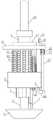
图1为本发明的结构示意图。Fig. 1 is a structural schematic diagram of the present invention.
图2为本发明图1的左视示意图。Fig. 2 is a schematic left view of Fig. 1 of the present invention.
图3为本发明图1的俯视示意图。FIG. 3 is a schematic top view of FIG. 1 of the present invention.
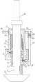
图4为本发明内部结构示意图。Fig. 4 is a schematic diagram of the internal structure of the present invention.
图5为本发明立体结构示意图。Fig. 5 is a schematic diagram of the three-dimensional structure of the present invention.
图6为本发明导向杆与弧形板配合的剖视示意图。Fig. 6 is a schematic cross-sectional view of the cooperation between the guide rod and the arc-shaped plate of the present invention.
图7为本发明导向杆与弧形板配合的立体示意图。Fig. 7 is a three-dimensional schematic diagram of the cooperation between the guide rod and the arc-shaped plate of the present invention.
图8为端面凸轮的立体结构示意图。Fig. 8 is a schematic diagram of the three-dimensional structure of the end cam.
具体实施方式Detailed ways
以下结合附图对本发明的具体实施方式作进一步详细说明。The specific implementation manners of the present invention will be described in further detail below in conjunction with the accompanying drawings.
由图1至图8给出,一种产科宫腔微波治疗设备,包括安装杆1、固定在安装杆1的下端的微波探头2,微波探头2背离安装杆1的一端设有圆台状的引导件3,引导件3背离微波探头2一端直径较小,引导件3设置为下端尖的圆台状,便于对该微波治疗装置通过患者的阴道进入到宫颈和宫腔内,对患者的患处进行微波治疗,其特征在于,所述安装杆1上同轴套有圆盘4,圆盘4上固定有套筒5,圆盘4上周向均布设有多个与圆盘4上下滑动连接的导向杆6,导向杆6的下端均固定有朝向微波探头2的弧形板7,各弧形板7依次接触形成圆筒状结构,导向杆6向下穿过套筒5,导向杆6上设有限位孔,限位孔滑动连接有限位块8,限位块8和限位孔的底部之间设有限位压簧9,限位块8在限位压簧9的作用下能够伸出限位孔且其上部与套筒5接触对导向杆6进行限位,当导向杆6上连接限位块8伸出限位孔,此时限位压簧9带动导向杆6和限位块8向上运动,故限位块8挡在套筒5上,微波探头2向弧形板7上的投影与弧形板7重合,弧形板7的长度长于微波探头2,此时限位块8伸出限位孔与套筒5接触时,弧形板7反射微波探头2发射到该弧形板7上的微波,阻止微波从此处散出,实现对微波探头2辐射范围的调节。导向杆6伸出圆盘4一端设有使导向杆6向上运动的驱动压簧10,所述安装杆1上同轴转动套有端面凸轮11,端面凸轮11的工作面分为一个波峰区12和一个波谷区13,波峰区12接触的导向杆6上连接的限位块8位于套筒5的下方,导向杆6上的限位块8缩回至限位孔则该导向杆6在驱动压簧10的作用下与端面凸轮11的波谷区13接触,所述弧形板7由反射微波的材质制作。本发明通过调节弧形板7,使得弧形板7与微波探头2位于同一高度,进而实现通过弧形板7来实现对微波探头2发出的微波的辐射范围的调节。转动端面凸轮11,端面凸轮11的波峰区12依次与导向杆6接触,波峰区12压着导向杆6向下运动,并且限位块8在限位压簧9的作用下伸出限位孔阻挡在套筒5上,导向杆6和弧形板7进行限位。当需要对弧形板7进行复位时将限位块8推送到限位孔内,在驱动压簧10的作用,限位块8随着导向杆6一起伸缩进入到套筒5内,此时弧形板7也随着导向杆6向上运动,弧形板7不在对微波探头2发出的微波进行反射,弧形板7由反射微波的加工制作。所述圆盘4与套筒5为一体,且圆盘4的侧面与套筒5的侧面重合,弧形板7能够向上伸入到套筒内。As shown in Fig. 1 to Fig. 8, a microwave treatment equipment for obstetric uterine cavity includes a mounting rod 1 and a
所述安装杆1上设有与端面凸轮11同轴相对转动的复位盘14,所述复位盘14上下滑动连接有复位杆15,复位杆15的下端固定有复位块16,复位块16靠近安装杆1的一侧面为向下向安装杆1方向倾斜的倾斜面,复位块16位于限位块8的下端且倾斜面能带动限位块8缩回限位孔内。在限位块8伸出限位孔并与套筒5接触时,复位杆15向上拉动带动复位块16向上运动,复位块16上的倾斜面与限位块8接触,进而倾斜面向限位孔内挤压限位块8,限位块8脱离与套筒5的下底面接触后,导向杆6在驱动压簧10的带动下向上运动,限位块8也随着导向杆6进入到套筒5内,实现对弧形板7位置的调节,进而调节微波探头2的辐射范围。复位盘14套在端面凸轮上,与端面凸轮转动连接,转动复位盘14能够带动复位杆位置的移动,进而实现控制更多的弧形板缩回至套筒内。The installation rod 1 is provided with a
所述复位杆15上设有位于复位盘14下方的限位凸缘17,限位凸缘17和复位盘14之间设有复位弹簧22。在不对复位杆15施加作用力的情况下,复位杆15在复位弹簧22的作用下,使得复位块16不与限位块8接触。The
所述复位杆15向上伸出复位盘14,且伸出端设有安装块,安装块的一侧设有支撑座18,支撑座18的转动连接有操纵杆19,操纵杆19的一端中部设有滑槽,安装块上固定有伸入到滑槽内的驱动销,支撑座18与操纵杆19的中部转动连接。摁压操纵杆19的自由端,操纵杆19转动带动驱动销,驱动销在滑槽内滑动的同时带动复位杆15向上运动,进而控制限位块8控制限位块缩回到限位孔内。Described
所述导向杆6上设有位于圆盘4上方的导向凸缘20,所述驱动压簧10套在导向杆6上且位于导向凸缘20和圆盘4之间。设置导向凸缘20为了便于驱动压簧10的安装,驱动压簧10将作用力作用在导向凸缘20上进而使得导向杆6保持向上运动的趋势。The
所述安装杆1背离微波探头2的一端固定有连接杆21。在微波探头2进入到的病人患处时,连接杆21的一部分留在患者体外,医务人员通过连接杆21实现对安装杆1微波探头2的操纵,便于操纵微波探头2进入到患者体内。A connecting
所述端面凸轮11的波峰区12同时仅能与一个导向杆6接触,波峰区12与波谷区13平滑过渡。转动端面凸轮11,波峰区12转动一个位置,驱动一个导向杆6克服驱动压簧10的作用力向下运动,同时限位块8伸出套筒5,进而限位块8伸出限位孔阻挡在套筒5的下底面上。The
所述引导件3由反射微波的材质制作。引导件3的材料采用反射微波的材料,可以防止微波探头2发出的微波从引导件3方向辐射出,实现对微波辐射精准的控制。引导件3由反射微波的金属做成。The
所述弧形板7位于最下端时,弧形板7与引导件3接触,弧形板7的上端内侧面与安装杆1接触配合,安装杆1的下端面有反射微波的材质制作。弧形板7的上底面高于安装杆1的下底面,弧形板7的内侧面与安装杆1的外侧面的直径相同,弧形板7的在导向杆6带动下上下移动同时也与安装杆1上下滑动。弧形板7位于最下端时即限位块8与套筒5的下底面接触,对导向杆6和弧形板7进限位,此时微波探头2发出的微波仅能通过弧形板7没有向下伸出的位置辐射出来,所以根据病人的患处情况,调节弧形板7实现对微波探头2辐射范围的调节。安装杆1的下端或者整个安装杆1由反射微波的金属制作。When the arc-shaped
本发明在使用时,可以先通过内窥镜和微型摄像头确定病人患处范围,然后根据情况转动端面凸轮11调节弧形板7伸出的数量,实现对微波探头2辐射范围的调节,当需要对弧形板7进行复位即使得限位块8伸入到限位孔内,以及限位块8和弧形板7进入到套筒5内时,转动复位盘,使得复位块对着需要收回的弧形板7,然后通过摁压操纵杆19带动导向杆6向上运动,进而带动复位块16向上运动,复位块16的倾斜面推动限位块8缩回限位孔内,然后驱动压簧10带动弧形板7缩回套筒5内。When the present invention is in use, the scope of the patient's affected area can be determined first through the endoscope and the miniature camera, and then the
本发明的有益效果是:通过伸出套管的弧形板的数量,来控制微波探头2的辐射范围,实现对病人病处进行精确的控制治疗,减少对患者非病处的创伤,较少患者痛处,有利于术后的快速回复;利用端面凸轮的转动能够很好的控制弧形板伸出套筒,操作简单,同时,控制弧形板复位的机构简单,操纵方便。The beneficial effects of the present invention are: the radiation range of the
以上所述的实施例并非对本发明的范围进行限定,在不脱离本发明设计构思的前提下,本领域所属技术人员对本发明的技术方案作出的各种变形和改进,均应纳入本发明的权利要求书确定的保护范围内。The above-described embodiments do not limit the scope of the present invention. Without departing from the design concept of the present invention, various modifications and improvements made by those skilled in the art to the technical solution of the present invention shall be included in the rights of the present invention. within the scope of protection specified in the requirements.
Claims (7)
Priority Applications (1)
| Application Number | Priority Date | Filing Date | Title |
|---|---|---|---|
| CN202010476564.8ACN111821018B (en) | 2019-07-22 | 2019-07-22 | Microwave treatment equipment for uterine cavity of obstetrical department |
Applications Claiming Priority (2)
| Application Number | Priority Date | Filing Date | Title |
|---|---|---|---|
| CN201910659689.1ACN110384554B (en) | 2019-07-22 | 2019-07-22 | Microwave therapeutic device for uterine cavity for obstetrical department |
| CN202010476564.8ACN111821018B (en) | 2019-07-22 | 2019-07-22 | Microwave treatment equipment for uterine cavity of obstetrical department |
Related Parent Applications (1)
| Application Number | Title | Priority Date | Filing Date |
|---|---|---|---|
| CN201910659689.1ADivisionCN110384554B (en) | 2019-07-22 | 2019-07-22 | Microwave therapeutic device for uterine cavity for obstetrical department |
Publications (2)
| Publication Number | Publication Date |
|---|---|
| CN111821018A CN111821018A (en) | 2020-10-27 |
| CN111821018Btrue CN111821018B (en) | 2022-11-11 |
Family
ID=68286912
Family Applications (3)
| Application Number | Title | Priority Date | Filing Date |
|---|---|---|---|
| CN202010476564.8AActiveCN111821018B (en) | 2019-07-22 | 2019-07-22 | Microwave treatment equipment for uterine cavity of obstetrical department |
| CN201910659689.1AExpired - Fee RelatedCN110384554B (en) | 2019-07-22 | 2019-07-22 | Microwave therapeutic device for uterine cavity for obstetrical department |
| CN202010476530.9AActiveCN111821017B (en) | 2019-07-22 | 2019-07-22 | Microwave therapeutic device for uterine cavity for obstetrical department |
Family Applications After (2)
| Application Number | Title | Priority Date | Filing Date |
|---|---|---|---|
| CN201910659689.1AExpired - Fee RelatedCN110384554B (en) | 2019-07-22 | 2019-07-22 | Microwave therapeutic device for uterine cavity for obstetrical department |
| CN202010476530.9AActiveCN111821017B (en) | 2019-07-22 | 2019-07-22 | Microwave therapeutic device for uterine cavity for obstetrical department |
Country Status (1)
| Country | Link |
|---|---|
| CN (3) | CN111821018B (en) |
Citations (6)
| Publication number | Priority date | Publication date | Assignee | Title |
|---|---|---|---|---|
| CN2608034Y (en)* | 2002-06-13 | 2004-03-31 | 南京市新技术应用研究所 | Microwave tumour therapeutic equipment |
| CN101484083A (en)* | 2006-06-30 | 2009-07-15 | 麦迪威公司 | Radio-frequency based catheter system and method for ablating biological tissues |
| WO2013076145A1 (en)* | 2011-11-21 | 2013-05-30 | Elexxion Ag | Method for treating humans and/or animals |
| CN105848601A (en)* | 2013-12-23 | 2016-08-10 | 科瑞欧医疗有限公司 | Surgical snare with ability to deliver electromagnetic energy and/or thermal plasma into biological tissue |
| CN107041773A (en)* | 2017-04-18 | 2017-08-15 | 中国人民解放军第二军医大学第二附属医院 | Pedicle of vertebral arch cropper |
| CN206499772U (en)* | 2016-11-15 | 2017-09-19 | 王生玲 | A kind of gynemetrics's uterine cavity microwave therapy equipment |
Family Cites Families (13)
| Publication number | Priority date | Publication date | Assignee | Title |
|---|---|---|---|---|
| FR2717375B1 (en)* | 1994-03-18 | 1996-05-03 | Sadis Bruker Spectrospin | Endocavitary applicator, in particular for heating by microwave radiation of the uterus. |
| CA2551831A1 (en)* | 2004-01-29 | 2005-08-11 | Ekos Corporation | Small vessel ultrasound catheter |
| US20080065059A1 (en)* | 2006-09-08 | 2008-03-13 | Marc Lukowiak | Microwave devices for transcutaneous treatments |
| EP2355738B1 (en)* | 2008-11-10 | 2015-08-19 | Microcube, LLC | Devices for applying energy to bodily tissues |
| US8409187B2 (en)* | 2009-09-08 | 2013-04-02 | Covidien Lp | Microwave antenna probe with high-strength ceramic coupler |
| BR112012006059B8 (en)* | 2009-09-18 | 2021-06-22 | Viveve Inc | apparatus and system for remodeling a therapeutic zone in the tissue underlying a mucosal epithelium of female genital tissue |
| US9655557B2 (en)* | 2011-02-04 | 2017-05-23 | Minerva Surgical, Inc. | Methods and systems for evaluating the integrity of a uterine cavity |
| JP5763263B2 (en)* | 2011-04-08 | 2015-08-12 | コビディエン エルピー | Flexible microwave catheter for natural or artificial lumens |
| CN105919666A (en)* | 2012-03-16 | 2016-09-07 | 女康乐公司 | Therapy equipment for repairing female vaginal tissue |
| US20130281920A1 (en)* | 2012-04-20 | 2013-10-24 | Elwha LLC, a limited liability company of the State of Delaware | Endometrial Ablation |
| CN202589654U (en)* | 2012-06-06 | 2012-12-12 | 王建新 | Cervical microwave hyperthermia radiator |
| CN104524698B (en)* | 2014-12-25 | 2017-06-23 | 深圳希能量科技有限公司 | A kind of cell repair instrument for woman vagina |
| JP7191694B2 (en)* | 2015-09-30 | 2022-12-19 | ジ・エ・エッメ・エッセ・エッレ・エッレ | Device for electromagnetic ablation of tissue |
- 2019
- 2019-07-22CNCN202010476564.8Apatent/CN111821018B/enactiveActive
- 2019-07-22CNCN201910659689.1Apatent/CN110384554B/ennot_activeExpired - Fee Related
- 2019-07-22CNCN202010476530.9Apatent/CN111821017B/enactiveActive
Patent Citations (6)
| Publication number | Priority date | Publication date | Assignee | Title |
|---|---|---|---|---|
| CN2608034Y (en)* | 2002-06-13 | 2004-03-31 | 南京市新技术应用研究所 | Microwave tumour therapeutic equipment |
| CN101484083A (en)* | 2006-06-30 | 2009-07-15 | 麦迪威公司 | Radio-frequency based catheter system and method for ablating biological tissues |
| WO2013076145A1 (en)* | 2011-11-21 | 2013-05-30 | Elexxion Ag | Method for treating humans and/or animals |
| CN105848601A (en)* | 2013-12-23 | 2016-08-10 | 科瑞欧医疗有限公司 | Surgical snare with ability to deliver electromagnetic energy and/or thermal plasma into biological tissue |
| CN206499772U (en)* | 2016-11-15 | 2017-09-19 | 王生玲 | A kind of gynemetrics's uterine cavity microwave therapy equipment |
| CN107041773A (en)* | 2017-04-18 | 2017-08-15 | 中国人民解放军第二军医大学第二附属医院 | Pedicle of vertebral arch cropper |
Also Published As
| Publication number | Publication date |
|---|---|
| CN110384554A (en) | 2019-10-29 |
| CN111821017A (en) | 2020-10-27 |
| CN110384554B (en) | 2020-06-30 |
| CN111821018A (en) | 2020-10-27 |
| CN111821017B (en) | 2022-11-11 |
Similar Documents
| Publication | Publication Date | Title |
|---|---|---|
| CN108451562B (en) | Stepless regulating and expanding device for craniocerebral lumen | |
| CN111821018B (en) | Microwave treatment equipment for uterine cavity of obstetrical department | |
| CN211704788U (en) | Semi-disposable balloon uterine manipulator | |
| CN110025369A (en) | A kind of new-type gynemetrics's midwifery device | |
| CN209645428U (en) | A kind of moxibustion device of automatic adjustment | |
| CN110464479A (en) | A kind of urological surgery protective device | |
| CN210873660U (en) | Special expander of urethral stricture patient | |
| CN113331937B (en) | Auxiliary hemostatic device for hepatobiliary pancreatic surgery | |
| CN207412301U (en) | Eye probe with removable ultrasonic generating unit | |
| CN209713087U (en) | A kind of uterus raising device that can oppress uterine cavity automatically | |
| CN116509487B (en) | A hemostatic device for vaginal wall puncture points after assisted reproduction egg retrieval | |
| CN114949547A (en) | Drainage tube fixing device that glandular surgery nursing was used | |
| CN103767745B (en) | A kind of anterior cervical vertebrae self-retractor system | |
| CN221963725U (en) | Microwave ablation needle positioning device for hemangioma treatment | |
| CN210118724U (en) | A support frame for gynaecology and obstetrics's spotlight inspection lamp | |
| CN219517417U (en) | An automatic continuous pressurized cholangiography injector | |
| CN219835800U (en) | Obstetric apparatus for women | |
| CN221903946U (en) | Clinical uterine curettage device for obstetrics and gynecology department | |
| CN216653161U (en) | Uterine cavity radiotherapy applicator channel probe | |
| CN206630656U (en) | Laparoscope cervical carcinoma operation uterus raising device | |
| CN220588550U (en) | A surgical positioning device | |
| CN110464590A (en) | Bladder assists compressorium on manual pubis | |
| CN222676473U (en) | Ultrasonic auxiliary interventional therapy device | |
| CN221533950U (en) | Cardiovascular intervention operation puncture positioning device | |
| CN221180940U (en) | Urethral anastomosis auxiliary device in robot prostate cancer radical operation |
Legal Events
| Date | Code | Title | Description |
|---|---|---|---|
| PB01 | Publication | ||
| PB01 | Publication | ||
| SE01 | Entry into force of request for substantive examination | ||
| SE01 | Entry into force of request for substantive examination | ||
| TA01 | Transfer of patent application right | ||
| TA01 | Transfer of patent application right | Effective date of registration:20221020 Address after:Room 110, building a0-2, Hefei Yulong agricultural machinery market, Cuozhen Town, Feidong County, Hefei City, Anhui Province Applicant after:Hefei Yuankang Information Technology Co.,Ltd. Address before:No. 312, Gongnong Road, Wancheng District, Nanyang City, Henan Province Applicant before:NANYANG CITY CENTER Hospital | |
| GR01 | Patent grant | ||
| GR01 | Patent grant | ||
| TR01 | Transfer of patent right | ||
| TR01 | Transfer of patent right | Effective date of registration:20241029 Address after:No. 581 West Street, Zhongzhao Township, Neihuang County, Anyang City, Henan Province 455000 Patentee after:Anyang Yongyuan Technical Service Center (sole proprietorship) Country or region after:China Address before:Room 110, building a0-2, Hefei Yulong agricultural machinery market, Cuozhen Town, Feidong County, Hefei City, Anhui Province Patentee before:Hefei Yuankang Information Technology Co.,Ltd. Country or region before:China | |
| TR01 | Transfer of patent right | ||
| TR01 | Transfer of patent right | Effective date of registration:20250317 Address after:464000 Genqin Cultural Integration Industrial Park C-096, 15th Floor, Yihe Capital Building, Gushi County, Xinyang City, Henan Province Patentee after:Xinyang Hongfeng Technology Development Co.,Ltd. Country or region after:China Address before:No. 581 West Street, Zhongzhao Township, Neihuang County, Anyang City, Henan Province 455000 Patentee before:Anyang Yongyuan Technical Service Center (sole proprietorship) Country or region before:China |