CN111820981A - Surgical device including trocar lock and trocar connection indicator - Google Patents
Surgical device including trocar lock and trocar connection indicatorDownload PDFInfo
- Publication number
- CN111820981A CN111820981ACN202010305048.9ACN202010305048ACN111820981ACN 111820981 ACN111820981 ACN 111820981ACN 202010305048 ACN202010305048 ACN 202010305048ACN 111820981 ACN111820981 ACN 111820981A
- Authority
- CN
- China
- Prior art keywords
- pair
- assembly
- trocar
- outer tube
- release button
- Prior art date
- Legal status (The legal status is an assumption and is not a legal conclusion. Google has not performed a legal analysis and makes no representation as to the accuracy of the status listed.)
- Pending
Links
- 230000007246mechanismEffects0.000claimsabstractdescription28
- 244000261422Lysimachia clethroidesSpecies0.000claimsdescription10
- 230000000007visual effectEffects0.000claimsdescription8
- 230000008878couplingEffects0.000description29
- 238000010168coupling processMethods0.000description29
- 238000005859coupling reactionMethods0.000description29
- 238000012546transferMethods0.000description23
- 238000013519translationMethods0.000description15
- 238000006243chemical reactionMethods0.000description7
- 238000000034methodMethods0.000description6
- 230000008901benefitEffects0.000description5
- 230000009466transformationEffects0.000description5
- 238000001356surgical procedureMethods0.000description4
- 230000000712assemblyEffects0.000description3
- 238000000429assemblyMethods0.000description3
- 230000014759maintenance of locationEffects0.000description3
- 230000007704transitionEffects0.000description3
- 230000015572biosynthetic processEffects0.000description2
- 238000005520cutting processMethods0.000description2
- 238000003780insertionMethods0.000description2
- 230000037431insertionEffects0.000description2
- 238000012986modificationMethods0.000description2
- 230000004048modificationEffects0.000description2
- 230000003213activating effectEffects0.000description1
- 230000004888barrier functionEffects0.000description1
- 238000004140cleaningMethods0.000description1
- 230000000994depressogenic effectEffects0.000description1
- 239000000284extractSubstances0.000description1
- 230000012447hatchingEffects0.000description1
- 238000010438heat treatmentMethods0.000description1
- 238000010879hemorrhoidectomyMethods0.000description1
- 238000004519manufacturing processMethods0.000description1
- 239000000463materialSubstances0.000description1
- 238000012805post-processingMethods0.000description1
- 238000012958reprocessingMethods0.000description1
- 238000002271resectionMethods0.000description1
Images


Classifications
- A—HUMAN NECESSITIES
- A61—MEDICAL OR VETERINARY SCIENCE; HYGIENE
- A61B—DIAGNOSIS; SURGERY; IDENTIFICATION
- A61B17/00—Surgical instruments, devices or methods
- A61B17/11—Surgical instruments, devices or methods for performing anastomosis; Buttons for anastomosis
- A61B17/115—Staplers for performing anastomosis, e.g. in a single operation
- A61B17/1155—Circular staplers comprising a plurality of staples
- A—HUMAN NECESSITIES
- A61—MEDICAL OR VETERINARY SCIENCE; HYGIENE
- A61B—DIAGNOSIS; SURGERY; IDENTIFICATION
- A61B17/00—Surgical instruments, devices or methods
- A61B2017/00367—Details of actuation of instruments, e.g. relations between pushing buttons, or the like, and activation of the tool, working tip, or the like
- A61B2017/00371—Multiple actuation, e.g. pushing of two buttons, or two working tips becoming operational
- A—HUMAN NECESSITIES
- A61—MEDICAL OR VETERINARY SCIENCE; HYGIENE
- A61B—DIAGNOSIS; SURGERY; IDENTIFICATION
- A61B17/00—Surgical instruments, devices or methods
- A61B2017/00367—Details of actuation of instruments, e.g. relations between pushing buttons, or the like, and activation of the tool, working tip, or the like
- A61B2017/00398—Details of actuation of instruments, e.g. relations between pushing buttons, or the like, and activation of the tool, working tip, or the like using powered actuators, e.g. stepper motors, solenoids
- A—HUMAN NECESSITIES
- A61—MEDICAL OR VETERINARY SCIENCE; HYGIENE
- A61B—DIAGNOSIS; SURGERY; IDENTIFICATION
- A61B17/00—Surgical instruments, devices or methods
- A61B2017/0046—Surgical instruments, devices or methods with a releasable handle; with handle and operating part separable
- A—HUMAN NECESSITIES
- A61—MEDICAL OR VETERINARY SCIENCE; HYGIENE
- A61B—DIAGNOSIS; SURGERY; IDENTIFICATION
- A61B17/00—Surgical instruments, devices or methods
- A61B2017/0046—Surgical instruments, devices or methods with a releasable handle; with handle and operating part separable
- A61B2017/00464—Surgical instruments, devices or methods with a releasable handle; with handle and operating part separable for use with different instruments
- A—HUMAN NECESSITIES
- A61—MEDICAL OR VETERINARY SCIENCE; HYGIENE
- A61B—DIAGNOSIS; SURGERY; IDENTIFICATION
- A61B17/00—Surgical instruments, devices or methods
- A61B2017/0046—Surgical instruments, devices or methods with a releasable handle; with handle and operating part separable
- A61B2017/00473—Distal part, e.g. tip or head
- A—HUMAN NECESSITIES
- A61—MEDICAL OR VETERINARY SCIENCE; HYGIENE
- A61B—DIAGNOSIS; SURGERY; IDENTIFICATION
- A61B17/00—Surgical instruments, devices or methods
- A61B2017/00477—Coupling
- A—HUMAN NECESSITIES
- A61—MEDICAL OR VETERINARY SCIENCE; HYGIENE
- A61B—DIAGNOSIS; SURGERY; IDENTIFICATION
- A61B17/00—Surgical instruments, devices or methods
- A61B2017/00526—Methods of manufacturing
- A—HUMAN NECESSITIES
- A61—MEDICAL OR VETERINARY SCIENCE; HYGIENE
- A61B—DIAGNOSIS; SURGERY; IDENTIFICATION
- A61B17/00—Surgical instruments, devices or methods
- A61B2017/00681—Aspects not otherwise provided for
- A61B2017/00734—Aspects not otherwise provided for battery operated
- A—HUMAN NECESSITIES
- A61—MEDICAL OR VETERINARY SCIENCE; HYGIENE
- A61B—DIAGNOSIS; SURGERY; IDENTIFICATION
- A61B90/00—Instruments, implements or accessories specially adapted for surgery or diagnosis and not covered by any of the groups A61B1/00 - A61B50/00, e.g. for luxation treatment or for protecting wound edges
- A61B90/08—Accessories or related features not otherwise provided for
- A61B2090/0807—Indication means
- A61B2090/0808—Indication means for indicating correct assembly of components, e.g. of the surgical apparatus
Landscapes
- Health & Medical Sciences (AREA)
- Life Sciences & Earth Sciences (AREA)
- Surgery (AREA)
- Heart & Thoracic Surgery (AREA)
- Engineering & Computer Science (AREA)
- Biomedical Technology (AREA)
- Nuclear Medicine, Radiotherapy & Molecular Imaging (AREA)
- Medical Informatics (AREA)
- Molecular Biology (AREA)
- Animal Behavior & Ethology (AREA)
- General Health & Medical Sciences (AREA)
- Public Health (AREA)
- Veterinary Medicine (AREA)
- Surgical Instruments (AREA)
Abstract
Description
Translated fromChinese相关申请的交叉引用CROSS-REFERENCE TO RELATED APPLICATIONS
本申请要求2019年4月22日提交的美国临时专利申请序列第62/836,950号的权益和优先权,所述临时专利申请的全部内容由此以引用的方式并入。This application claims the benefit of and priority to US Provisional Patent Application Serial No. 62/836,950, filed April 22, 2019, the entire contents of which are hereby incorporated by reference.
本申请要求2019年4月22日提交的美国临时申请序列第62/836,933号的权益和优先权,所述临时申请的全部内容由此以引用的方式并入。This application claims the benefit of and priority to US Provisional Application Serial No. 62/836,933, filed April 22, 2019, the entire contents of which are hereby incorporated by reference.
本申请要求2019年4月22日提交的美国临时申请序列第62/836,918号的权益和优先权,所述临时申请的全部内容由此以引用的方式并入。This application claims the benefit of and priority to US Provisional Application Serial No. 62/836,918, filed April 22, 2019, the entire contents of which are hereby incorporated by reference.
本申请还为部分继续申请,其要求2018年5月7日提交的美国专利申请序列第15/972,606号的权益和优先权,所述专利申请的全部内容由此以引用的方式并入。This application, which is also a continuation-in-part, claims the benefit of, and priority to, US Patent Application Serial No. 15/972,606, filed May 7, 2018, the entire contents of which are hereby incorporated by reference.
本申请还为部分继续申请,其要求2016年5月17日提交的美国专利申请序列第15/157,136号的权益和优先权,所述专利申请的全部内容由此以引用的方式并入。This application, which is also a continuation-in-part, claims the benefit of and priority to US Patent Application Serial No. 15/157,136, filed May 17, 2016, the entire contents of which are hereby incorporated by reference.
技术领域technical field
本公开涉及动力手术装置。更具体地,本公开涉及包括套管针锁和套管针连接指示器的可重复使用手持型机电手术装置。The present disclosure relates to powered surgical devices. More particularly, the present disclosure relates to a reusable hand-held electromechanical surgical device including a trocar lock and a trocar connection indicator.
背景技术Background technique
用于执行如缝合术、痔切除术和粘膜切除术的手术程序的圆形缝合器械为众所周知的。这些装置包括砧座组件,所述砧座组件具有中心杆和支撑在中心杆上的砧座头。砧座组件的中心杆可附接到圆形缝合器械的套管针,其使得砧座组件能够线性平移。通常,在手术程序期间,将圆形缝合器械的工具组件插入组织的一个或多个管状区段中以连接组织区段或从组织区段内移除患病或受损组织。在手术程序之后,期望对圆形缝合器械进行再加工,以便使手术程序的总成本最小化。再处理通常需要经由高压灭菌等清洁圆形缝合器械。为了提高后处理的效率,需要套管针的可移除性。Circular suturing instruments are well known for performing surgical procedures such as suturing, hemorrhoidectomy, and mucosal resection. These devices include an anvil assembly having a center rod and an anvil head supported on the center rod. The center rod of the anvil assembly is attachable to the trocar of the circular stapling instrument, which enables linear translation of the anvil assembly. Typically, during a surgical procedure, a tool assembly of a circular stapling instrument is inserted into one or more tubular segments of tissue to connect tissue segments or to remove diseased or damaged tissue from within tissue segments. After a surgical procedure, it is desirable to rework the circular stapling instrument in order to minimize the overall cost of the surgical procedure. Reprocessing typically requires cleaning of circular stapling instruments via autoclaving or the like. In order to improve the efficiency of post-processing, the removability of the trocar is required.
因此,鉴于此,期望提供锁和指示器,所述指示器告知终端用户(例如,医生、护士、临床医生等)套管针适当地附接到下面的圆形缝合器械。Therefore, in view of this, it is desirable to provide locks and indicators that inform end users (eg, doctors, nurses, clinicians, etc.) that the trocar is properly attached to the underlying circular stapling instrument.
发明内容SUMMARY OF THE INVENTION
根据本公开的方面,提供用于将手术再装载件连接到机电手柄组件的适配器组件。适配器组件包括外管;可释放地紧固在外管的远侧末端内的套管针组件,所述套管针组件包括限定其中的一对开口的套管针壳体,其中一对开口处于彼此相对径向延伸关系;和被配置成可释放地将套管针组件紧固在外管内的套管针组件释放机构。According to an aspect of the present disclosure, an adapter assembly for connecting a surgical reload to an electromechanical handle assembly is provided. The adapter assembly includes an outer tube; a trocar assembly releasably secured within a distal tip of the outer tube, the trocar assembly including a trocar housing defining a pair of openings therein, wherein the pair of openings are in each other in relatively radially extending relationship; and a trocar assembly release mechanism configured to releasably secure the trocar assembly within the outer tube.
释放机构包括可滑动地支撑在外管内的一对销,其中每个销选择性地可接收在套管针壳体中形成的一对开口的相应开口内;支撑在外管中并且在延伸状态和按下状态之间可移动的释放按钮;和可滑动地支撑在外管中的弹簧夹,所述弹簧夹将释放按钮和一对销互连。The release mechanism includes a pair of pins slidably supported within the outer tube, wherein each pin is selectively receivable within a corresponding opening of a pair of openings formed in the trocar housing; supported in the outer tube and in an extended state and pressed a release button movable between lower states; and a spring clip slidably supported in the outer tube, the spring clip interconnecting the release button and a pair of pins.
当释放按钮处于延伸状态时,弹簧夹作用于一对销以维持一对销安置在套管针壳体的一对开口内以维持套管针组件连接到外管。当释放按钮处于按下状态时,弹簧夹作用于一对销,以维持所述一对销从套管针壳体的一对开口缩回,以从外管释放套管针组件。When the release button is in the extended state, the spring clip acts on the pair of pins to maintain the pair of pins seated within the pair of openings in the trocar housing to maintain the connection of the trocar assembly to the outer tube. When the release button is in the depressed state, the spring clip acts on a pair of pins to maintain the pair of pins retracted from the pair of openings in the trocar housing to release the trocar assembly from the outer tube.
当释放按钮处于按下状态时,一对销可径向向外延伸,由此向用户提供套管针组件未锁定在外管中的视觉指示。When the release button is in the depressed state, a pair of pins can extend radially outward, thereby providing a visual indication to the user that the trocar assembly is not locked in the outer tube.
套管针组件释放机构可另外包括偏置构件,其支撑在外管内并且作用于释放按钮以将释放按钮推动到延伸状态。The trocar assembly release mechanism may additionally include a biasing member supported within the outer tube and acting on the release button to urge the release button to the extended state.
套管针组件释放机构的弹簧夹可包括连接到释放按钮的后跨部;和从后跨部延伸的一对腿。每条腿可沿其长度限定鹅颈管,使得与一对腿中的每个的近侧部分相比,一对腿中的每个的远侧部分彼此更靠近。The spring clip of the trocar assembly release mechanism may include a backspan connected to the release button; and a pair of legs extending from the backspan. Each leg may define a gooseneck along its length such that the distal portion of each of the pair of legs is closer to each other than the proximal portion of each of the pair of legs.
释放按钮在延伸状态和按下状态之间的移动可引起弹簧夹的一对腿的鹅颈管部分穿过一对销。Movement of the release button between the extended state and the depressed state causes the gooseneck portions of a pair of legs of the spring clip to pass through a pair of pins.
当释放按钮处于延伸状态时,弹簧夹的一对腿的远侧部分可与一对销相关联。当释放按钮处于按下状态时,弹簧夹的一对腿的近侧部分可与一对销相关联。The distal portions of the pair of legs of the spring clip can be associated with a pair of pins when the release button is in the extended state. The proximal portions of the pair of legs of the spring clip can be associated with a pair of pins when the release button is in the depressed state.
套管针组件可另外包括可滑动地安置在套管针壳体的腔内的套管针构件,其中套管针构件和套管针壳体彼此键连以阻止相对于彼此旋转,其中套管针构件包括限定尖端的远侧末端和限定内部螺纹孔的近侧末端;和具有与套管针构件的螺纹孔接合的带螺纹的远侧部分和用于接收来自机电手柄组件的旋转力的近侧力接收特征的驱动螺钉。The trocar assembly may additionally include a trocar member slidably disposed within the lumen of the trocar housing, wherein the trocar member and the trocar housing are keyed to each other to prevent rotation relative to each other, wherein the cannula The needle member includes a distal tip defining a tip and a proximal tip defining an internally threaded bore; and a threaded distal portion that engages the threaded bore of the trocar member and a proximal end for receiving rotational force from the electromechanical handle assembly. Drive screw for side force receiving feature.
外管可包括穿过其外表面形成的一对开口。外管的一对开口中的每个可与一对销中的相应一个对准。The outer tube may include a pair of openings formed through its outer surface. Each of the pair of openings of the outer tube may be aligned with a corresponding one of the pair of pins.
当释放按钮处于按下状态时,一对销可至少部分安置在外管的一对开口内。A pair of pins may be at least partially seated within a pair of openings in the outer tube when the release button is in the depressed state.
根据本公开的另一个方面,提供用于将手术再装载件连接到机电手柄组件的适配器组件。适配器组件包括外管;可释放地紧固在外管的远侧末端内的套管针组件,所述套管针组件包括限定其中的一对开口的套管针壳体,其中一对开口处于彼此相对径向延伸关系;和被配置成可释放地将套管针组件紧固在外管内的套管针组件释放机构。According to another aspect of the present disclosure, an adapter assembly for connecting a surgical reload to an electromechanical handle assembly is provided. The adapter assembly includes an outer tube; a trocar assembly releasably secured within a distal tip of the outer tube, the trocar assembly including a trocar housing defining a pair of openings therein, wherein the pair of openings are in each other in relatively radially extending relationship; and a trocar assembly release mechanism configured to releasably secure the trocar assembly within the outer tube.
释放机构包括可旋转地支撑在外管的相对径向侧上的一对释放按钮,其中每个释放按钮选择性地可接收在套管针壳体中形成的一对开口的相应开口内,每个释放按钮在释放状态和接合状态之间可移动;和支撑在外管中并且与一对释放按钮中的相应一个相关联的一对偏置构件,其中偏置构件将一对释放按钮推动到接合状态并且与套管针壳体接合。The release mechanism includes a pair of release buttons rotatably supported on opposite radial sides of the outer tube, wherein each release button is selectively receivable within a corresponding opening of a pair of openings formed in the trocar housing, each a release button is movable between a released state and an engaged state; and a pair of biasing members supported in the outer tube and associated with a respective one of the pair of release buttons, wherein the biasing member urges the pair of release buttons to the engaged state and engages with the trocar housing.
当释放按钮处于接合状态时,释放按钮安置在套管针壳体的一对开口内以维持套管针组件连接到外管。当释放按钮处于释放按下状态时,释放按钮脱离套管针壳体的一对开口以从外管释放套管针组件。When the release button is in the engaged state, the release button is positioned within a pair of openings in the trocar housing to maintain the trocar assembly connected to the outer tube. When the release button is in the released depressed state, the release button disengages from a pair of openings in the trocar housing to release the trocar assembly from the outer tube.
套管针释放机构可包括一对枢轴销,每个枢轴销可枢转地支撑相应的释放按钮。The trocar release mechanism may include a pair of pivot pins, each pivot pin pivotally supporting a corresponding release button.
每个释放按钮可基本上为半圆形,基本上绕其相应枢轴销延伸180°。Each release button may be substantially semi-circular, extending substantially 180° about its respective pivot pin.
每个释放按钮可限定远侧面,相应偏置构件的一部分与所述远侧面接合,以将释放按钮推动到接合状态并且与套管针壳体接合。Each release button may define a distal side with which a portion of the corresponding biasing member engages to urge the release button into engagement and into engagement with the trocar housing.
每个释放按钮可限定突出到尾部的近端面,其中当释放按钮处于接合状态时,尾部进入套管针壳体的一对开口的相应开口,以维持套管针组件连接到外管。Each release button may define a proximal face protruding into the tail, wherein when the release button is in the engaged state, the tail enters a corresponding opening of a pair of openings in the trocar housing to maintain the trocar assembly connected to the outer tube.
每个释放按钮可包括在其上形成的抓持特征。Each release button may include a gripping feature formed thereon.
根据本公开的另一个方面,提供用于将手术再装载件连接到手柄组件的适配器组件。适配器组件包括外管;安置在外管的远侧部分内的套管针组件;和套管针释放机构。套管针释放机构包括可滑动地支撑在外管内的一对销;支撑在外管中并且在延伸状态和按下状态之间可移动的释放按钮;可滑动地支撑在外管中的弹簧夹,弹簧夹将释放按钮和一对销互连,使得当释放按钮处于延伸状态时,套管针组件固定到外管,并且当释放按钮处于按下状态时,套管针组件从外管可移除;和固定到释放按钮使得弹簧夹紧固到释放按钮的弹簧闩锁。According to another aspect of the present disclosure, an adapter assembly for connecting a surgical reload to a handle assembly is provided. The adapter assembly includes an outer tube; a trocar assembly disposed within the distal portion of the outer tube; and a trocar release mechanism. The trocar release mechanism includes a pair of pins slidably supported in the outer tube; a release button supported in the outer tube and movable between an extended state and a depressed state; a spring clip slidably supported in the outer tube, a spring clip interconnecting the release button and a pair of pins such that when the release button is in the extended state, the trocar assembly is secured to the outer tube, and when the release button is in the depressed state, the trocar assembly is removable from the outer tube; and Secure to the release button so that the spring clip is fastened to the spring latch of the release button.
套管针释放机构可包括可滑动地支撑在外管内的一对销,其中弹簧夹将释放按钮与一对销互连。The trocar release mechanism may include a pair of pins slidably supported within the outer tube, wherein a spring clip interconnects the release button with the pair of pins.
在释放按钮的延伸状态中,弹簧夹可维持一对销处于延伸位置,并且在释放按钮的按下状态中,其中弹簧夹将一对销从延伸位置抽出到抽出位置。In the extended state of the release button, the spring clip may maintain the pair of pins in the extended position, and in the depressed state of the release button, wherein the spring clip extracts the pair of pins from the extended position to the extracted position.
套管针组件可包括套管针壳体和可滑动地安置在套管针壳体内的套管针。The trocar assembly may include a trocar housing and a trocar slidably positioned within the trocar housing.
套管针壳体可限定一对径向相对的开口,套管针释放机构的每个销接收在一对开口的相应开口内,以将套管针组件紧固在外管内处于延伸位置和从相应开口缩回处于缩回位置。The trocar housing may define a pair of diametrically opposed openings, each pin of the trocar release mechanism being received within a corresponding opening of the pair of openings to secure the trocar assembly within the outer tube in the extended position and from the corresponding opening. The opening is retracted in the retracted position.
在延伸位置,一对销可被配置成向用户提供套管针组件锁定在外管中的视觉指示。In the extended position, a pair of pins may be configured to provide a visual indication to the user that the trocar assembly is locked in the outer tube.
外管可限定一对相对的开口。套管针释放机构所述一对销可具有完全延伸位置,其中每个销延伸到相对开口中的相应一个中,其中一对销被配置成向用户提供套管针组件未紧固在外管内的视觉指示。The outer tube may define a pair of opposing openings. Trocar Release Mechanism The pair of pins may have a fully extended position, wherein each pin extends into a respective one of the opposing openings, wherein the pair of pins is configured to provide a user with a trocar assembly that is not secured within the outer tube visual indication.
套管针释放机构可另外包括偏置构件,其支撑在外管内并且作用于释放按钮以将释放按钮推动到延伸状态。The trocar release mechanism may additionally include a biasing member supported within the outer tube and acting on the release button to urge the release button to the extended state.
弹簧闩锁可包括平面主体和从平面主体垂直延伸到释放按钮的内表面以将弹簧闩锁固定到释放按钮的铆接突片。The spring latch may include a planar body and a rivet tab extending perpendicularly from the planar body to an inner surface of the release button to secure the spring latch to the release button.
弹簧夹当通过弹簧闩锁紧固到释放按钮时可在两个自由度上可移动。The spring clip is movable in two degrees of freedom when fastened to the release button by a spring latch.
弹簧夹可包括通过弹簧闩锁紧固到释放按钮的后跨部;和从后跨部延伸的一对腿,其中每个腿沿其长度限定鹅颈管,使得与一对腿中的每个的近侧部分相比,一对腿中的每个的远侧部分彼此更靠近。The spring clip may include a backspan secured to the release button by a spring latch; and a pair of legs extending from the backspan, wherein each leg defines a gooseneck along its length such that each of the pair of legs communicates with each other. The distal portions of each of the pair of legs are closer to each other than the proximal portions of the legs.
释放按钮在延伸状态和按下状态之间的移动可移动簧夹的一对腿的鹅颈管部分穿过一对销。Movement of the release button between the extended state and the depressed state moves the gooseneck portions of the pair of legs of the movable spring clip through a pair of pins.
当释放按钮处于延伸状态时,弹簧夹的每个腿的远侧部分可与相应销相关联,并且当释放按钮处于按下状态时,弹簧夹的每个腿的近侧部分可与相应销相关联。A distal portion of each leg of the spring clip can be associated with a corresponding pin when the release button is in the extended state, and a proximal portion of each leg of the spring clip can be associated with a corresponding pin when the release button is in the depressed state link.
适配器组件可被配置成可释放地紧固到机电手柄组件。The adapter assembly can be configured to be releasably fastened to the electromechanical handle assembly.
根据本公开的另一个方面,提供制造适配器组件的方法,并且所述方法包括将弹簧闩锁固定到释放按钮的内表面,其包括将弹簧闩锁的主体与释放按钮的内表面对齐;加热从弹簧闩锁的主体垂直延伸的弹簧闩锁的两个铆接突片;和将铆接突片驱动到释放按钮的内表面中以将弹簧闩锁固定到释放按钮。方法另外包括将释放按钮安置在适配器组件的外管中限定的空间内;和提供被配置成安置在外管内并且通过弹簧夹通过弹簧闩锁紧固到释放按钮紧固在外管内的套管针组件。According to another aspect of the present disclosure, there is provided a method of manufacturing an adapter assembly, and the method includes securing a spring latch to an inner surface of a release button, comprising aligning a body of the spring latch with the inner surface of the release button; heating the two rivet tabs of the spring latch extending vertically from the body of the spring latch; and driving the rivet tabs into the inner surface of the release button to secure the spring latch to the release button. The method additionally includes positioning a release button within a space defined in an outer tube of the adapter assembly; and providing a trocar assembly configured to be seated within the outer tube and secured within the outer tube by a spring clip through a spring latch to the release button.
将铆接突片驱动到释放按钮的内表面中可包括将片熔化孔铆接到内表面中。Driving the riveting tab into the inner surface of the release button may include riveting the tab melt hole into the inner surface.
方法可另外包括在将弹簧闩锁固定到内表面之前将弹簧夹的后跨部定位在释放按钮的内表面中限定的凹槽内。The method may additionally include positioning the rear span of the spring clip within a groove defined in the inner surface of the release button prior to securing the spring latch to the inner surface.
将弹簧闩锁的主体与释放按钮的内表面对齐可包括将从主体延伸的保持突片定位安置在凹槽内的弹簧夹的后跨部的一部分上方。Aligning the body of the spring latch with the inner surface of the release button may include positioning a retention tab extending from the body over a portion of the rear span of the spring clip positioned within the groove.
方法可另外包括在将弹簧闩锁固定到释放按钮的内表面之后将弹簧夹的后跨部定位在释放按钮的内表面中限定的凹槽内。The method may additionally include positioning the rear span of the spring clip within a groove defined in the inner surface of the release button after securing the spring latch to the inner surface of the release button.
方法可再另外包括切割平片材料以形成弹簧闩锁的主体、铆接突片和保持突片,铆接突片从主体的相对侧延伸,并且保持突片从定位在主体的相对侧之间的主体的一侧延伸;向下弯曲铆接突片,使得铆接突片与由主体限定的平面正交定位;和将保持突片向上弯曲到鹅颈管配置,使得保持突片的内表面为朝向安置在由主体限定的平面中的弯曲部的中心的弓形。The method can still additionally include cutting a flat sheet of material to form a body of the spring latch, rivet tabs extending from opposing sides of the body, and retaining tabs from the body positioned between the opposing sides of the body extend one side of the rivet tab; bend the rivet tab downward so that the rivet tab is positioned orthogonally to the plane defined by the body; and bend the retention tab up to the gooseneck configuration such that the inner surface of the retention tab is positioned toward the The arcuate shape of the center of the bend in the plane defined by the body.
附图说明Description of drawings
在本文中参考附图描述本公开的实施例,其中:Embodiments of the present disclosure are described herein with reference to the accompanying drawings, wherein:
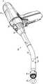
图1为根据本公开的实施例的包括手柄组件、适配器组件和再装载件的手持型手术装置的透视图;1 is a perspective view of a handheld surgical device including a handle assembly, an adapter assembly, and a reload in accordance with an embodiment of the present disclosure;
图2为图1的手柄组件其中零件分离的透视图;Figure 2 is a perspective view of the handle assembly of Figure 1 with parts separated;
图3为图2的手柄组件的动力手柄的马达组件和控制组件在零件分离的情况下的透视图;3 is a perspective view of the motor assembly and control assembly of the power handle of the handle assembly of FIG. 2 with the parts separated;
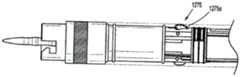
图4为适配器组件在没有再装载件固定到其远侧末端的情况下的透视图;Figure 4 is a perspective view of the adapter assembly without a reload secured to its distal tip;
图5为如穿过图4的剖面线5-5截取的图4的适配器组件的剖视图;5 is a cross-sectional view of the adapter assembly of FIG. 4 as taken through section line 5-5 of FIG. 4;
图6为如穿过图4的剖面线6-6截取的图4的适配器组件的剖视图;6 is a cross-sectional view of the adapter assembly of FIG. 4 as taken through section line 6-6 of FIG. 4;
图7为部分地以影线示出的适配器组件的透视图,其说明其第一力/旋转传递/转换组件;7 is a perspective view of the adapter assembly, partially hatched, illustrating its first force/rotation transfer/translation assembly;
图8为图7的第一力/旋转传递/转换组件的透视图;Figure 8 is a perspective view of the first force/rotation transfer/transformation assembly of Figure 7;
图9为图7的第一力/旋转传递/转换组件的套管针组件的其中零件已分离的透视图;9 is a perspective view of the trocar assembly of the first force/rotation transfer/conversion assembly of FIG. 7 with parts separated;
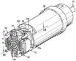
图10为图7的第一力/旋转传递/转换组件的远侧末端部分的透视图,其说明其支撑块和与其相关联的套管针锁组件;Figure 10 is a perspective view of the distal tip portion of the first force/rotation transfer/conversion assembly of Figure 7 illustrating its support block and its associated trocar lock assembly;
图11为图7的第一力/旋转传递/转换组件的远侧末端部分的透视图,其中支撑块以影线示出;11 is a perspective view of the distal tip portion of the first force/rotation transfer/translation assembly of FIG. 7 with the support block shown in hatching;
图12为如穿过图10的12-12截取的剖视图;Figure 12 is a cross-sectional view as taken through 12-12 of Figure 10;
图13为如穿过图10的13-13截取的剖视图;Figure 13 is a cross-sectional view as taken through 13-13 of Figure 10;
图14为如穿过图13的14-14截取的剖视图;Figure 14 is a cross-sectional view as taken through 14-14 of Figure 13;
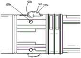
图15为图4的细节的指定区域的放大视图;Figure 15 is an enlarged view of a designated area of the detail of Figure 4;
图16为如穿过图15的16-16截取的剖视图;Figure 16 is a cross-sectional view as taken through 16-16 of Figure 15;
图17为如穿过图15的17-17截取的剖视图;Figure 17 is a cross-sectional view as taken through 17-17 of Figure 15;
图18为图7的第一力/旋转传递/转换组件的远侧末端部分的透视图,其说明在按下状态中与其相关联的套管针锁组件;Figure 18 is a perspective view of the distal tip portion of the first force/rotation transfer/conversion assembly of Figure 7 illustrating the trocar lock assembly associated therewith in the depressed state;
图19为图7的第一力/旋转传递/转换组件的远侧末端部分的透视图,其说明在未压下状态中与其相关联的套管针锁组件;Figure 19 is a perspective view of the distal tip portion of the first force/rotation transfer/conversion assembly of Figure 7 illustrating the trocar lock assembly associated therewith in an undepressed state;
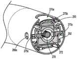
图20为在没有再装载件紧固到其远侧末端的情况下适配器组件的远侧末端的透视图,其说明根据本公开的另一实施例的套管针锁组件;20 is a perspective view of the distal tip of the adapter assembly without a reload fastened to its distal tip, illustrating a trocar lock assembly according to another embodiment of the present disclosure;
图21为其中移除适配器组件的外管的图20的套管针锁组件的顶部平面视图;Figure 21 is a top plan view of the trocar lock assembly of Figure 20 with the outer tube of the adapter assembly removed;
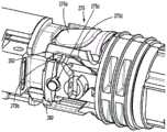
图22为其中移除适配器组件的外管和支撑块的图20的套管针锁组件的顶部平面视图,其说明在第二锁定位置中的套管针锁组件;22 is a top plan view of the trocar lock assembly of FIG. 20 with the outer tube and support block of the adapter assembly removed, illustrating the trocar lock assembly in a second locked position;
图23为图22的细节的指定区域的放大视图,其说明在第一解锁位置中的套管针锁组件;Figure 23 is an enlarged view of the designated area of the detail of Figure 22 illustrating the trocar lock assembly in the first unlocked position;
图24为部分地以影线示出的图4的适配器组件的透视图,其说明其第二力/旋转传递/转换组件;和24 is a perspective view, partially hatched, of the adapter assembly of FIG. 4 illustrating its second force/rotation transfer/translation assembly; and
图25为部分地以影线示出的图4的适配器组件的透视图,其说明其第三力/旋转传递/转换组件。25 is a perspective view of the adapter assembly of FIG. 4, partially hatched, illustrating its third force/rotation transfer/transformation assembly.
具体实施方式Detailed ways
现在参考附图详细描述本公开的实施例,其中在若干视图中的每一个中,类似的附图标号表示相同或对应元件。如本文所使用,术语“近侧”是指手术装置的一部分或其部件更靠近用户,并且术语“远侧”是指手术装置的一部分或其部件更远离用户。Embodiments of the present disclosure will now be described in detail with reference to the drawings, wherein like reference numerals refer to the same or corresponding elements throughout the several views. As used herein, the term "proximal" refers to a portion of the surgical device or components thereof that is closer to the user, and the term "distal" refers to a portion of the surgical device or components thereof that is further away from the user.
现在转向图1,根据本公开的实施例的手术装置10呈动力手持型机电器械的形式。手术装置包括手柄组件100、适配器组件200、再装载件400和砧座组件510。手柄组件100被配置成用于与适配器组件200选择性地连接,并且继而,适配器组件200被配置成用于与再装载件400选择性地连接。Turning now to FIG. 1 , a
另外将仅以公开本公开的方面所必要的程度来描述手柄组件100、适配器组件200和再装载件400。为了详细描述示例性手柄组件、适配器组件和再装载件的结构和功能,可参考共同拥有美国专利申请公开第2016/0310134号和美国专利申请序列第15/972,606号,所述专利申请中的每一个的全部内容以引用的方式并入本文中。Additionally, handle
现在参考图2,手柄组件100包括动力手柄101,和被配置成选择性地接收和包住动力手柄101的外部或外壳壳体110。外壳壳体110包括可联接在一起的近侧半区段110a和远侧半区段110b。外壳壳体110包括多个致动器112(例如,手指致动的控制按钮、旋钮、肘节、滑动件、接口等),以用于在向其中施加相应力时激活手术装置10(图1)的各种功能。Referring now to FIG. 2 , the
外壳壳体110的远侧半区段110b限定连接部分114(例如,凹座),其被配置成收纳或接收适配器组件200的对应驱动联接组件210(图5)。无菌屏障板组件120选择性地支撑在连接部分114后面的外壳壳体110的远侧半区段110b中。板组件120包括板122,所述板122可旋转地支撑三个联接轴124a、124b、124c,并且具有支撑在其上的电连接器126。电连接器126包括芯片并且限定多个接触路径,每个接触路径包括用于延伸跨过板122的电连接的电管道。当板组件120安置在外壳壳体110内时,联接轴124a、124b、124c和电连接器126的远侧末端安置或安放在外壳壳体110的连接部分114内,以电和/或机械接合适配器组件200的相应的对应特征,如下文将更详细地描述。The distal half-
动力手柄101具有内手柄壳体111,其包括近侧半区段111a和远端半区段111b,它们联接在一起以在其中容纳动力单元芯组件130。动力单元芯组件130被配置成控制手柄组件100的各种操作并且因此控制手术装置10的各种操作。The power handle 101 has an inner handle housing 111 that includes a proximal half-section 111a and a distal half-
内部手柄壳体111的远侧半区段111b被配置和适配成支撑动力单元芯组件130的控制板132,使得当动力手柄101安置在外壳壳体110内时控制板132抵靠外壳壳体110的板组件120。内部手柄壳体111的远侧半区段111b还支撑多个致动器接口116,其与外壳壳体110的相应致动器112操作性地对准。The
如图2和3所示,动力单元芯组件130包括被配置成为手柄组件100的电部件中的任一个供电的电池电路140、控制器电路板142和可再充电电池144。控制器电路板142包括马达控制器电路板142a、主控制器电路板142b和将马达控制器电路板142a与主控制器电路板142b互连的第一带状电缆142c。显示屏134支撑在主控制器电路板142b上,并且穿过设置在内部手柄壳体111的近侧半区段111a中的澄清或透明窗口113可见。USB连接器136(或其它数据连接器)也支撑在主控制器电路板142b上,并且可穿过动力单元芯组件130的控制板132来访问。As shown in FIGS. 2 and 3 , the power
动力单元芯组件130另外包括安置在马达控制器电路板142a和主控制器电路板142b之间的第一马达152、第二马达154和第三马达156。第一马达152、第二马达154和第三马达156中的每个电连接到控制器电路板142和电池144,并且由安置在马达控制器电路板142a上的相应马达控制器控制,所述马达控制器继而联接到安置在主控制器电路板142b上的相应主控制器。The power
第一马达152、第二马达154和第三马达156中的每个支撑在马达支架148上,使得从第一马达152、第二马达154和第三马达156延伸的相应马达轴152a、154a、156a可旋转地安置在马达支架148的相应孔内。马达支架148可旋转地支撑键连到第一马达152、第二马达154和第三马达156的相应马达轴152a、154a、156a的三个可旋转驱动连接器套筒152b、154b、156b。当动力手柄101安置在外壳壳体10内时,驱动连接器套筒152b、154b、156b不可旋转地接收外壳壳体110的板组件120的相应联接轴124a、124b、124c的近侧末端,并且各自被弹簧偏置远离相应马达152、154、156。Each of the
马达支架148也支撑电插座149。电插座149通过第二带状电缆142d与主控制器电路板142b电连接。电插座149限定用于接收从外壳壳体110的板组件120的穿通连接器126延伸的相应电接触或片的多个电狭槽。The
由相应的第一马达152、第二马达154和第三马达156旋转马达轴152a、154a、156a用于驱动适配器组件200的轴和/或齿轮部件,以便执行手柄组件100的各种操作,如下文将更详细地描述。
在使用中,当使适配器组件200配合手柄组件100时,手柄组件100的联接轴124a、124b、124c中的每一个与适配器组件200的对应可旋转连接器套筒218、220、222(图6)联接。在这方面,在对应联接轴124a、124b、124c和连接器套筒218、222、220之间的接口被键连,使得手柄组件100的联接轴124a、124b、124c中的每个的旋转引起适配器组件200的对应连接器套筒218、222、220的对应旋转。In use, when the
手柄组件100的联接轴124a、124b、124c被配置成通过相应马达152、154、156独立地旋转,使得(一个或多个)旋转力选择性地从手柄组件100的马达152、154、156传递到适配器组件200。手柄组件100的一个或多个联接轴124a、124b、124c的选择性旋转允许手柄组件100选择性地致动再装载件400的不同功能。The coupling shafts 124a, 124b, 124c of the
现在转向图4,适配器组件200被配置成将手柄组件100的(一个或多个)联接轴124a、124b、124c(图2)的旋转转换成可用于实现手术装置10(图1)的各种功能的轴向平移。适配器组件200包括适配器或旋钮壳体202和从旋钮壳体202的远侧末端延伸的外管206。旋钮壳体202和外管206被配置和定尺寸以容纳和支撑适配器组件200的部件。旋钮壳体202包括驱动联接组件210,其被配置和适配成连接到手柄组件100的外壳壳体110的连接部分114(图2)。外管206包括固定地支撑在其远侧末端处的连接器套筒290。连接器套筒290被配置成选择性地将再装载件400(图1)紧固到适配器组件200。Turning now to FIG. 4,
如图4和5所示,适配器组件200包括旋转组件230,其被配置成使得适配器组件200能够相对于手柄组件100旋转。具体地,适配器组件200的旋钮壳体202和外管206相对于适配器组件200的驱动联接组件210可旋转。旋转组件230包括锁定按钮232,其可操作地支撑在旋钮壳体202上并且被配置成用于致动旋转组件230。当旋转组件230处于解锁配置时,旋钮壳体202和外管206相对于驱动联接组件210沿适配器组件200的纵向轴线“X”可旋转。当旋转组件230处于锁定配置时,旋钮壳体202和外管206相对于驱动联接组件210旋转地紧固。As shown in FIGS. 4 and 5 , the
适配器组件200另外包括支撑在适配器组件200的驱动联接组件210上的附接/脱离按钮234。在使用中,当适配器组件200连接到手柄组件100的外壳壳体110时,附接/脱离按钮234将适配器组件200和手柄组件100彼此紧固和保持。当按下或致动附接/脱离按钮234时,适配器组件200和手柄组件100可彼此断开。The
适配器组件200另外包括限定在驱动联接组件210内的腔211,所述腔211被配置成接收电组件300的连接器组件320(图18),所述电组件300被配置成用于与手柄组件100、适配器组件200和再装载件400建立电连接,并且在手柄组件100、适配器组件200和再装载件400之间建立电连接,如下文另外详细描述。腔211可包括引导肋211,其被配置成接收销连接器组件320的印刷电路板324。The
如图6所说明,适配器组件200的驱动联接组件210在其中可旋转地支撑第一连接器套筒218、第二连接器套筒220和第三连接器套筒222,并且安置在旋钮壳体202内的内部壳体构件204在其中可旋转地支撑第一可旋转近侧驱动轴212、第二可旋转近侧驱动轴214和第三可旋转近侧驱动轴216。第一连接器套筒218、第二连接器套筒220和第三连接器套筒222中的每个被配置成与手柄组件100的相应联接轴124a、124c、124b(图2)配合。第一连接器套筒218、第二连接器套筒220和第三连接器套筒222中的每个另外被配置成与适配器组件200的相应的第一近侧驱动轴212、第二近侧驱动轴214和第三近侧驱动轴216的近侧末端配合,使得第一近侧驱动轴212、第二近侧驱动轴214和第三近侧驱动轴216中的每个充当旋转接收构件,以接收来自手柄组件100的相应联接轴124a、124c、124b的旋转力。6, the
适配器组件200包括安置在内部外壳构件204和外管206内的第一力/旋转传递/转换组件240、第二力/旋转传递/转换组件250和第三力/旋转传递/转换组件260。力/旋转传递/转换组件240、250、260中的每个被配置和适配成将手柄组件100的相应联接轴124a、124c、124b的旋转传递或转换成轴向平移,以实现再装载件400(图1)的操作,如下文将更详细地描述。The
如图6和7所示,第一力/旋转传递/转换组件240包括如上文所描述的第一可旋转近侧驱动轴212、第二可旋转近侧驱动轴281、可旋转远侧驱动轴282,和联接构件286。第一力/旋转传递/转换组件240,如图7-19所说明,另外包括可移除地支撑在外管206的远侧末端中的套管针组件270。套管针组件270包括管状外壳体272、可滑动地安置在管状外壳体272内的套管针构件274和可操作地接收在套管针构件274内用于相对于管状壳体272轴向移动套管针构件274的驱动螺钉276。具体来说,套管针构件274包括近侧末端274a,其具有接合驱动螺钉276的带螺纹的远侧部分276b的内部螺纹部分273。套管针构件274另外包括在其外表面中形成的至少一个纵向延伸扁平部274d,其与在管状壳体272中形成的对应扁平部272b配合,由此在驱动螺钉276旋转时阻止套管针构件274相对于管状壳体272旋转。套管针构件274的远侧末端274b被配置成选择性地接合砧座组件510(图1)。6 and 7, the first force/rotation transfer/translation assembly 240 includes a first rotatable proximal drive shaft 212, a second rotatable
套管针组件270的管状壳体272轴向和可旋转固定在适配器组件200的外导管206内。管状壳体272限定一对径向相对并且径向取向的开口272a,其被配置和定尺寸以与适配器组件200的套管针组件释放机构275(见图10-14和17)的一对锁销275c协作。继续参考图10-19,适配器组件200包括固定地安置在外管206内的支撑块292。一对锁销275c延伸穿过支撑块292并且进入套管针组件270的管状壳体272以将套管针组件270连接到适配器组件200。The
如图11-17所说明,套管针组件释放机构275包括枢转地支撑在铰链引导件293上和外管206中的释放按钮275a。释放按钮275a经由弹簧275d(见图14、18和19)偏置到锁定/延伸状态。套管针组件释放机构275另外包括弹簧夹275b,所述弹簧夹275b具有连接到释放按钮275a的后跨部和从后跨部延伸的一对腿,所述腿延伸穿过支撑块292并且横跨套管针组件270。弹簧夹275b的一对腿中的每个延伸穿过相应的锁销275c,所述锁销275c可滑动地安置在相应管状壳体272的径向开口272a和支撑块292的径向开口292a内。弹簧夹275b的一对腿中的每个沿其长度限定鹅颈管,使得与弹簧夹275b的一对腿中的每个的近侧部分相比,弹簧夹275b一对腿中的每个的远侧部分彼此更靠近。As illustrated in FIGS. 11-17 , the trocar
在使用中,当按下释放按钮275a时(例如在径向向内方向上,图15-18),释放按钮275a相对于套管针组件270横向移动弹簧夹275b。在弹簧夹275b相对于套管针组件270横向移动时,弹簧夹275b的一对腿平移穿过一对锁销275c,使得在每个腿中的鹅颈管用以凸出和径向向外推动一对锁销275c。具体地,一对锁销275c被弹簧夹275b的一对腿的鹅颈管部分横穿,从其远侧部分过渡到其近侧部分。这样移动时,一对锁销275c中的每个径向向外推动的距离足以使一对锁销275c中的每一个澄清管状壳体272的相应开口272a,并且在一个实施例中,从外管206突出或与外管206的外表面齐平。预期,外管206可包括在其中形成的开口206a(见图15和图17),所述开口206a与一对锁销275c中的每个对准。在一对锁销275c移开和澄清管状壳体272的情况下,套管针组件270可从适配器组件200的外管206的远侧末端内轴向缩回,或可插入到适配器组件200的外管206的远侧末端中。In use, when the
一对锁销275c从外管206径向向外突起(或基本上与外管206的外表面齐平)向终端用户提供没有套管针组件270插入到适配器组件200的外管206的远侧末端中,或套管针组件270不适当地插入到适配器组件200的外管206的远侧末端中的视觉指示。当套管针组件270恰当地插入到适配器组件200的外管206的远侧末端中时,套管针组件释放机构的275一对锁销275c与套管针组件270的管状壳体272的相应开口272a对准并且进入其中(见图19),以由此将套管针组件270锁定在适配器组件200的外管206的远侧末端内,并且由此向终端用户提供套管针组件270适当地插入到适配器组件200的外管206的远侧末端中的视觉指示。A pair of locking
现在转向图20-23,在替代实施例中,适配器组件200可包括套管针组件释放机构1275。如所说明,套管针组件释放机构1275包括经由相应枢轴销1275e可旋转地支撑在支撑块(未示出)上和外管206中的一对释放按钮1275a。每个释放按钮1275a经由相应偏置构件1275d(例如片弹簧)偏置到锁定状态。Turning now to FIGS. 20-23 , in an alternative embodiment, the
每个释放按钮1275a彼此相同,并且因此,本文将仅详细地描述一对释放按钮中的一个1275a。释放按钮1275a基本上为半圆形,绕枢轴销1275e延伸大约180°。释放按钮1275a限定远侧面或表面1275a',偏置构件1275d的一部分与所述远侧面或表面1275a'接合,以向近侧推动释放按钮1275a,并且近端面或表面突出到尾部1275a"。释放按钮1275a的外表面可包括在其上形成的手指抓持特征(例如肋、滚花等)。Each
释放按钮1275a在第一解锁位置和第二锁定位置之间可移动。如果或当套管针组件270不适当地插入到适配器组件200的外管206的远侧末端中时,释放按钮1275a通过套管针组件270从外导管206径向向外旋转或推动到第一解锁位置,由此向终端用户提供套管针组件270不适当地插入到适配器组件200的外管206的远侧末端中的视觉指示。当套管针组件270适当地插入到适配器组件200的外管206的远侧末端中时,通过偏置构件1275d旋转释放按钮1275a,使得其尾部1275a"接收在套管针组件270的管状壳体272的外表面中形成的凹座或凹口中(例如类似于管状壳体272的开口272a),释放按钮1275a径向向内旋转或推动到第二锁定位置。当释放按钮1275a处于第二锁定位置时,向终端用户提供套管针组件270适当地插入和锁定到适配器组件200的外管206的远侧末端中的视觉指示。
在一个实施例中,参考图23,尾部1275a"包括倒角远侧表面,以便于当释放按钮1275a处于第二锁定位置时,在套管针组件270连接到外管206期间接收或通过套管针组件270。尾部1275a"另外包括基本上正方形的近侧表面,以阻止当释放按钮1275a相对于套管针组件270的管状壳体272处于第二锁定位置时套管针组件270从外管206缩回或断开连接。In one embodiment, referring to FIG. 23, the
参考图1-9,在操作中,第一力/旋转传递/转换组件240用以推进/缩回适配器组件200的套管针组件270的套管针构件274,并且当砧座组件510连接到套管针构件274时打开/关闭再装载件400(图1)。具体地,当第一可旋转近侧驱动轴212由于第一连接器套筒218的旋转而旋转时,由于手柄组件100的第一联接轴124a(图2)的旋转,引起第二可旋转近侧驱动轴281旋转。第二可旋转近侧驱动轴281的旋转导致可旋转远侧驱动轴282的同时旋转。可旋转远侧驱动轴282的旋转引起联接构件286的同时旋转,这继而引起套管针组件270的驱动螺钉276的同时旋转。当驱动螺钉276在套管针构件274内并且相对于其旋转时,在套管针构件274和驱动螺钉276之间的接合(例如,螺纹接合)引起套管针构件274在套管针组件270的管状壳体272内的轴向平移。具体地,驱动螺钉276在第一方向上的旋转引起套管针构件274在第一方向上的轴向平移(例如,延伸或推进套管针组件270),并且驱动螺钉276在第二方向上的旋转引起套管针构件274在第二方向上的轴向平移(例如,缩回套管针组件270)。当砧座组件510连接到套管针构件274时,套管针构件274在第一方向上的轴向平移导致再装载件400打开,并且套管针构件274在第二方向上的轴向平移导致再装载件400的关闭。1-9, in operation, the first force/rotation transfer/conversion assembly 240 is used to advance/retract the
如图6和24所示,适配器组件200的第二力/旋转传递/转换组件250包括如上文所描述的第二近侧驱动轴214、第一联接轴251、行星齿轮组252、钉导螺钉253和钉驱动器254。适配器组件200的第二力/旋转传递/转换组件250还包括紧固到钉驱动器254的外部柔性带组件255。外部柔性带组件255包括第一柔性带255a和第二柔性带255b,所述第一柔性带255a和第二柔性带255b侧向地隔开并且在其近侧末端处连接到支撑环255c并且在其远侧末端处连接到支撑基部255d的近侧末端。外部柔性带组件255另外包括从支撑环255c向近侧延伸的第一连接延伸部255e和第二连接延伸部255f,所述第一连接延伸部255e和第二连接延伸部255f被配置成将外部柔性带组件255可操作地连接到钉驱动器254。第二力/旋转传递/转换组件250用以击发再装载件400的钉“S”(图13)用于抵靠砧座组件510形成。As shown in Figures 6 and 24, the second force/rotation transfer/
在操作中,当第二可旋转近侧驱动轴214由于第二连接器套筒220的旋转而旋转时,由于手柄组件100的第二联接轴124c(图2)的旋转,引起第一联接轴251旋转,这继而引起行星齿轮组252旋转。行星齿轮组252的旋转引起钉导螺钉253的同时旋转。当钉导螺钉253旋转时,引起钉驱动器254轴向平移,这继而引起外部柔性带组件255轴向平移。当外部柔性带组件255轴向平移时,支撑基部255d按压抵靠再装载件400的钉驱动器组件(未示出)的驱动器适配器,以向远侧推进驱动器并且从再装载件400的钉仓(未示出)并且抵靠砧座组件510击发钉用于钉在下层组织中的形成。In operation, when the second rotatable proximal drive shaft 214 is rotated due to rotation of the
参考图6和25,适配器组件200的第三力/旋转传递/转换组件260包括如上文所描述的第三近侧驱动轴216、第二联接轴261、中空轴269、行星齿轮组262、刀导螺钉263和刀驱动器264。适配器组件200的第三力/旋转传递/转换组件260还包括紧固到刀驱动器264的内部柔性带组件265。内部柔性带组件265包括第一柔性带265a和第二柔性带265b,所述第一柔性带265a和第二柔性带265b侧向地隔开并且在其近侧末端处连接到支撑环265c并且在其远侧末端处连接到支撑基部265d的近侧末端。第三力/旋转传递/转换组件260用以击发再装载件400的环形刀444(图13)。6 and 25, the third force/rotation transfer/transformation assembly 260 of the
在操作中,当第三可旋转近侧驱动轴216由于第三连接器套筒222的旋转而旋转时,由于手柄组件100的第三联接轴124b(图2)的旋转,引起第二联接轴261旋转,这继而引起中空轴269旋转。中空轴269的旋转导致行星齿轮组262的同时旋转,这继而引起刀导螺钉263旋转。当刀导螺钉263旋转时,引起刀驱动器264轴向平移,这继而引起内部柔性带组件265轴向平移。当内部柔性带组件265轴向平移时,支撑基部265d按压抵靠再装载件400的刀架(未示出),以向远侧推进刀架并且抵靠砧座组件510击发再装载件400的环形刀(未示出)以用于夹持在再装载件400中的组织的切割。In operation, when the third rotatable
所属领域的技术人员将理解,本文中所具体地描述并且附图中所示出的结构为非限制性示例性实施例,并且应将描述、公开和附图仅仅认作示例性特定实施例。因此,应当理解的是,本公开不限于所描述的精确实施例并且所属领域的技术人员可在不脱离本公开的范围或精神的情况下实现各种其它改变和修改。举例来说,本公开的电组件可被配置成用于经由多个相应的适配器组件与多个不同的再装载件一起使用,每个适配器组件被配置成用于由动力手柄组件和/或机器人手术系统致动和操纵。另外,可在不脱离本公开的范围的情况下将结合某些实施例所示出或描述的元件和特征与某些其它实施例的元件和特征组合,并且此类修改和变化也包括在本公开的范围内。因此,本公开的主题并不受到已特定地示出和描述的内容的限制。Those skilled in the art will understand that the structures specifically described herein and illustrated in the accompanying drawings are non-limiting exemplary embodiments and that the description, disclosure and drawings are to be considered as exemplary specific embodiments only. Therefore, it is to be understood that this disclosure is not limited to the precise embodiments described and that various other changes and modifications may be effected by those skilled in the art without departing from the scope or spirit of this disclosure. For example, the electrical assemblies of the present disclosure may be configured for use with a plurality of different reloads via a plurality of corresponding adapter assemblies, each adapter assembly configured for use by a power handle assembly and/or a robot Surgical system actuation and manipulation. In addition, elements and features shown or described in connection with certain embodiments may be combined with elements and features of certain other embodiments without departing from the scope of the present disclosure, and such modifications and changes are also included herein within the public domain. Accordingly, the subject matter of the present disclosure is not to be limited by what has been specifically shown and described.
Claims (15)
Translated fromChineseApplications Claiming Priority (8)
| Application Number | Priority Date | Filing Date | Title |
|---|---|---|---|
| US201962836933P | 2019-04-22 | 2019-04-22 | |
| US201962836918P | 2019-04-22 | 2019-04-22 | |
| US201962836950P | 2019-04-22 | 2019-04-22 | |
| US62/836,933 | 2019-04-22 | ||
| US62/836,918 | 2019-04-22 | ||
| US62/836,950 | 2019-04-22 | ||
| US16/829,185US11399839B2 (en) | 2018-05-07 | 2020-03-25 | Surgical devices including trocar lock and trocar connection indicator |
| US16/829,185 | 2020-03-25 |
Publications (1)
| Publication Number | Publication Date |
|---|---|
| CN111820981Atrue CN111820981A (en) | 2020-10-27 |
Family
ID=70390848
Family Applications (1)
| Application Number | Title | Priority Date | Filing Date |
|---|---|---|---|
| CN202010305048.9APendingCN111820981A (en) | 2019-04-22 | 2020-04-17 | Surgical device including trocar lock and trocar connection indicator |
Country Status (2)
| Country | Link |
|---|---|
| EP (1) | EP3730073B1 (en) |
| CN (1) | CN111820981A (en) |
Cited By (1)
| Publication number | Priority date | Publication date | Assignee | Title |
|---|---|---|---|---|
| WO2022257040A1 (en)* | 2021-06-09 | 2022-12-15 | Covidien Lp | Retractable trocar for circular stapling instruments |
Citations (4)
| Publication number | Priority date | Publication date | Assignee | Title |
|---|---|---|---|---|
| CN105520781A (en)* | 2014-10-21 | 2016-04-27 | 柯惠Lp公司 | Adapter assemblies, extension assemblies and connector assemblies for surgical equipment |
| CN106037851A (en)* | 2015-04-10 | 2016-10-26 | 柯惠Lp公司 | Adapter, Extender and Connector Assemblies for Surgical Devices |
| CN107374686A (en)* | 2016-05-17 | 2017-11-24 | 柯惠Lp公司 | Include the adapter assembly of removable trocar assembly |
| US20180280024A1 (en)* | 2015-06-12 | 2018-10-04 | Covidien Lp | Surgical anastomosis apparatus |
Family Cites Families (4)
| Publication number | Priority date | Publication date | Assignee | Title |
|---|---|---|---|---|
| EP3741309A1 (en) | 2015-04-22 | 2020-11-25 | Covidien LP | Handheld electromechanical surgical system |
| US10111684B2 (en)* | 2015-09-25 | 2018-10-30 | Covidien Lp | Adapter assembly including a removable trocar assembly |
| US10524797B2 (en)* | 2016-01-13 | 2020-01-07 | Covidien Lp | Adapter assembly including a removable trocar assembly |
| US11389263B2 (en)* | 2018-12-13 | 2022-07-19 | Covidien Lp | Lockout mechanisms for surgical instruments |
- 2020
- 2020-04-17CNCN202010305048.9Apatent/CN111820981A/enactivePending
- 2020-04-21EPEP20170564.7Apatent/EP3730073B1/enactiveActive
Patent Citations (4)
| Publication number | Priority date | Publication date | Assignee | Title |
|---|---|---|---|---|
| CN105520781A (en)* | 2014-10-21 | 2016-04-27 | 柯惠Lp公司 | Adapter assemblies, extension assemblies and connector assemblies for surgical equipment |
| CN106037851A (en)* | 2015-04-10 | 2016-10-26 | 柯惠Lp公司 | Adapter, Extender and Connector Assemblies for Surgical Devices |
| US20180280024A1 (en)* | 2015-06-12 | 2018-10-04 | Covidien Lp | Surgical anastomosis apparatus |
| CN107374686A (en)* | 2016-05-17 | 2017-11-24 | 柯惠Lp公司 | Include the adapter assembly of removable trocar assembly |
Cited By (1)
| Publication number | Priority date | Publication date | Assignee | Title |
|---|---|---|---|---|
| WO2022257040A1 (en)* | 2021-06-09 | 2022-12-15 | Covidien Lp | Retractable trocar for circular stapling instruments |
Also Published As
| Publication number | Publication date |
|---|---|
| EP3730073B1 (en) | 2024-10-30 |
| EP3730073A1 (en) | 2020-10-28 |
Similar Documents
| Publication | Publication Date | Title |
|---|---|---|
| US11534172B2 (en) | Electromechanical surgical stapler including trocar assembly release mechanism | |
| US11399839B2 (en) | Surgical devices including trocar lock and trocar connection indicator | |
| US11464592B2 (en) | Handheld electromechanical surgical system | |
| US11071561B2 (en) | Hand held electromechanical surgical handle assembly for use with surgical end effectors, and methods of use | |
| JP5425974B2 (en) | Surgical stapling device | |
| EP3189791B1 (en) | Adapter assemblies for interconnecting surgical loading units and handle assemblies | |
| US10729435B2 (en) | Adapter assemblies for interconnecting surgical loading units and handle assemblies | |
| US11786244B2 (en) | Manual retraction tool for use with an electromechanical surgical device | |
| US9023014B2 (en) | Quick connect assembly for use between surgical handle assembly and surgical accessories | |
| CN104274222B (en) | Surgical Devices and Surgical Adapters | |
| JP2020096890A (en) | Authentication and information system for reusable surgical instrument | |
| US10617486B2 (en) | Manual retraction tool for use with an electromechanical surgical device | |
| CN111743589B (en) | Loading unit and anastomat | |
| EP2668912A2 (en) | Loading unit detection assembly and surgical device for use therewith | |
| KR20240027156A (en) | Surgical stapler having locking articulation joint | |
| CN116616845B (en) | Handle with manual reset mechanism and anastomat | |
| CN111820981A (en) | Surgical device including trocar lock and trocar connection indicator | |
| US20250057518A1 (en) | Adapter assemblies and surgical loading units | |
| CN111110287B (en) | Surgical device including adapter and seal | |
| EP3730072A1 (en) | Electromechanical surgical stapler including trocar assembly release mechanism | |
| CN115252026A (en) | Actuator for cutting stapler and cutting stapler |
Legal Events
| Date | Code | Title | Description |
|---|---|---|---|
| PB01 | Publication | ||
| PB01 | Publication | ||
| SE01 | Entry into force of request for substantive examination | ||
| SE01 | Entry into force of request for substantive examination | ||
| AD01 | Patent right deemed abandoned | ||
| AD01 | Patent right deemed abandoned | Effective date of abandoning:20250325 |