CN111810856A - An LED fluorescent lamp - Google Patents
An LED fluorescent lampDownload PDFInfo
- Publication number
- CN111810856A CN111810856ACN202010595076.9ACN202010595076ACN111810856ACN 111810856 ACN111810856 ACN 111810856ACN 202010595076 ACN202010595076 ACN 202010595076ACN 111810856 ACN111810856 ACN 111810856A
- Authority
- CN
- China
- Prior art keywords
- lamp
- lamp tube
- tube
- led fluorescent
- main body
- Prior art date
- Legal status (The legal status is an assumption and is not a legal conclusion. Google has not performed a legal analysis and makes no representation as to the accuracy of the status listed.)
- Granted
Links
- 239000004831Hot glueSubstances0.000claimsabstractdescription58
- 238000009792diffusion processMethods0.000claimsabstractdescription46
- 239000011521glassSubstances0.000claimsabstractdescription38
- 230000007704transitionEffects0.000claimsabstractdescription36
- 239000011248coating agentSubstances0.000claimsabstractdescription35
- 238000000576coating methodMethods0.000claimsabstractdescription35
- 239000000853adhesiveSubstances0.000claimsabstractdescription13
- 230000001070adhesive effectEffects0.000claimsabstractdescription13
- 230000002093peripheral effectEffects0.000claimsdescription64
- 229910052751metalInorganic materials0.000claimsdescription57
- 239000002184metalSubstances0.000claimsdescription57
- 239000003292glueSubstances0.000claimsdescription27
- 238000010438heat treatmentMethods0.000claimsdescription7
- 239000012212insulatorSubstances0.000claimsdescription4
- 239000010410layerSubstances0.000description81
- 238000000034methodMethods0.000description29
- VTYYLEPIZMXCLO-UHFFFAOYSA-LCalcium carbonateChemical compound[Ca+2].[O-]C([O-])=OVTYYLEPIZMXCLO-UHFFFAOYSA-L0.000description18
- 230000000694effectsEffects0.000description17
- 229910000679solderInorganic materials0.000description16
- 239000000463materialSubstances0.000description15
- OKTJSMMVPCPJKN-UHFFFAOYSA-NCarbonChemical compound[C]OKTJSMMVPCPJKN-UHFFFAOYSA-N0.000description14
- 238000005728strengtheningMethods0.000description12
- 238000003466weldingMethods0.000description11
- 206010014357Electric shockDiseases0.000description9
- 239000002313adhesive filmSubstances0.000description9
- 229910000019calcium carbonateInorganic materials0.000description9
- 239000000919ceramicSubstances0.000description8
- 230000006698inductionEffects0.000description8
- 238000005342ion exchangeMethods0.000description8
- 239000004033plasticSubstances0.000description8
- 229920003023plasticPolymers0.000description8
- 239000000126substanceSubstances0.000description8
- ATJFFYVFTNAWJD-UHFFFAOYSA-NTinChemical compound[Sn]ATJFFYVFTNAWJD-UHFFFAOYSA-N0.000description7
- 238000001816coolingMethods0.000description7
- 150000002500ionsChemical class0.000description7
- 230000008569processEffects0.000description7
- 239000002344surface layerSubstances0.000description7
- 239000002562thickening agentSubstances0.000description7
- JOPDZQBPOWAEHC-UHFFFAOYSA-Htristrontium;diphosphateChemical compound[Sr+2].[Sr+2].[Sr+2].[O-]P([O-])([O-])=O.[O-]P([O-])([O-])=OJOPDZQBPOWAEHC-UHFFFAOYSA-H0.000description7
- 239000000203mixtureSubstances0.000description6
- 230000004048modificationEffects0.000description6
- 238000012986modificationMethods0.000description6
- -1polysiloxanePolymers0.000description6
- 229910001415sodium ionInorganic materials0.000description6
- XLYOFNOQVPJJNP-UHFFFAOYSA-NwaterSubstancesOXLYOFNOQVPJJNP-UHFFFAOYSA-N0.000description6
- VYPSYNLAJGMNEJ-UHFFFAOYSA-NSilicium dioxideChemical compoundO=[Si]=OVYPSYNLAJGMNEJ-UHFFFAOYSA-N0.000description5
- 230000008901benefitEffects0.000description5
- 238000013461designMethods0.000description5
- 230000003287optical effectEffects0.000description5
- 239000000843powderSubstances0.000description5
- NTHWMYGWWRZVTN-UHFFFAOYSA-Nsodium silicateChemical compound[Na+].[Na+].[O-][Si]([O-])=ONTHWMYGWWRZVTN-UHFFFAOYSA-N0.000description5
- 238000002834transmittanceMethods0.000description5
- 239000004115Sodium SilicateSubstances0.000description4
- 238000001723curingMethods0.000description4
- 230000006872improvementEffects0.000description4
- 238000004806packaging method and processMethods0.000description4
- 239000002245particleSubstances0.000description4
- 229920002545silicone oilPolymers0.000description4
- 229910052911sodium silicateInorganic materials0.000description4
- 238000005476solderingMethods0.000description4
- 239000000758substrateSubstances0.000description4
- UFHFLCQGNIYNRP-UHFFFAOYSA-NHydrogenChemical compound[H][H]UFHFLCQGNIYNRP-UHFFFAOYSA-N0.000description3
- CTQNGGLPUBDAKN-UHFFFAOYSA-NO-XyleneChemical compoundCC1=CC=CC=C1CCTQNGGLPUBDAKN-UHFFFAOYSA-N0.000description3
- 229910052782aluminiumInorganic materials0.000description3
- XAGFODPZIPBFFR-UHFFFAOYSA-NaluminiumChemical compound[Al]XAGFODPZIPBFFR-UHFFFAOYSA-N0.000description3
- 230000004323axial lengthEffects0.000description3
- 238000002425crystallisationMethods0.000description3
- 239000008367deionised waterSubstances0.000description3
- 229910021641deionized waterInorganic materials0.000description3
- 239000001257hydrogenSubstances0.000description3
- 229910052739hydrogenInorganic materials0.000description3
- 238000007373indentationMethods0.000description3
- 238000004519manufacturing processMethods0.000description3
- 238000004382pottingMethods0.000description3
- 238000012545processingMethods0.000description3
- 230000002787reinforcementEffects0.000description3
- 150000003839saltsChemical class0.000description3
- 239000000741silica gelSubstances0.000description3
- 229910002027silica gelInorganic materials0.000description3
- 230000000007visual effectEffects0.000description3
- 239000008096xyleneSubstances0.000description3
- LFQSCWFLJHTTHZ-UHFFFAOYSA-NEthanolChemical compoundCCOLFQSCWFLJHTTHZ-UHFFFAOYSA-N0.000description2
- KFZMGEQAYNKOFK-UHFFFAOYSA-NIsopropanolChemical compoundCC(C)OKFZMGEQAYNKOFK-UHFFFAOYSA-N0.000description2
- OAICVXFJPJFONN-UHFFFAOYSA-NPhosphorusChemical compound[P]OAICVXFJPJFONN-UHFFFAOYSA-N0.000description2
- 239000004793PolystyreneSubstances0.000description2
- LSNNMFCWUKXFEE-UHFFFAOYSA-NSulfurous acidChemical compoundOS(O)=OLSNNMFCWUKXFEE-UHFFFAOYSA-N0.000description2
- XLOMVQKBTHCTTD-UHFFFAOYSA-NZinc monoxideChemical compound[Zn]=OXLOMVQKBTHCTTD-UHFFFAOYSA-N0.000description2
- 230000004308accommodationEffects0.000description2
- 230000015572biosynthetic processEffects0.000description2
- 239000002131composite materialSubstances0.000description2
- 230000005672electromagnetic fieldEffects0.000description2
- 230000017525heat dissipationEffects0.000description2
- 238000009413insulationMethods0.000description2
- 239000007788liquidSubstances0.000description2
- 238000002156mixingMethods0.000description2
- 238000000465mouldingMethods0.000description2
- 229920003229poly(methyl methacrylate)Polymers0.000description2
- 239000004417polycarbonateSubstances0.000description2
- 239000005020polyethylene terephthalateSubstances0.000description2
- 229920000139polyethylene terephthalatePolymers0.000description2
- 239000004926polymethyl methacrylateSubstances0.000description2
- 229920001296polysiloxanePolymers0.000description2
- 238000002310reflectometryMethods0.000description2
- 239000011734sodiumSubstances0.000description2
- 229940074404sodium succinateDrugs0.000description2
- 238000007711solidificationMethods0.000description2
- 230000008023solidificationEffects0.000description2
- 239000000243solutionSubstances0.000description2
- 125000000391vinyl groupChemical group[H]C([*])=C([H])[H]0.000description2
- 229920002554vinyl polymerPolymers0.000description2
- KXGFMDJXCMQABM-UHFFFAOYSA-N2-methoxy-6-methylphenolChemical compound[CH]OC1=CC=CC([CH])=C1OKXGFMDJXCMQABM-UHFFFAOYSA-N0.000description1
- RSWGJHLUYNHPMX-UHFFFAOYSA-NAbietic-SaeureNatural productsC12CCC(C(C)C)=CC2=CCC2C1(C)CCCC2(C)C(O)=ORSWGJHLUYNHPMX-UHFFFAOYSA-N0.000description1
- 239000004925Acrylic resinSubstances0.000description1
- 229920000178Acrylic resinPolymers0.000description1
- 229910000838Al alloyInorganic materials0.000description1
- 229910021532CalciteInorganic materials0.000description1
- RYGMFSIKBFXOCR-UHFFFAOYSA-NCopperChemical compound[Cu]RYGMFSIKBFXOCR-UHFFFAOYSA-N0.000description1
- WHXSMMKQMYFTQS-UHFFFAOYSA-NLithiumChemical compound[Li]WHXSMMKQMYFTQS-UHFFFAOYSA-N0.000description1
- 229920000297RayonPolymers0.000description1
- KHPCPRHQVVSZAH-HUOMCSJISA-NRosinNatural productsO(C/C=C/c1ccccc1)[C@H]1[C@H](O)[C@@H](O)[C@@H](O)[C@@H](CO)O1KHPCPRHQVVSZAH-HUOMCSJISA-N0.000description1
- 229920001800ShellacPolymers0.000description1
- 229910004298SiO 2Inorganic materials0.000description1
- JOJBKERXUKYXGJ-UHFFFAOYSA-J[Ca++].[Sr++].[O-]C([O-])=O.OP([O-])([O-])=OChemical compound[Ca++].[Sr++].[O-]C([O-])=O.OP([O-])([O-])=OJOJBKERXUKYXGJ-UHFFFAOYSA-J0.000description1
- 238000002835absorbanceMethods0.000description1
- 238000010521absorption reactionMethods0.000description1
- 230000009471actionEffects0.000description1
- 230000032683agingEffects0.000description1
- 239000003513alkaliSubstances0.000description1
- 229910001413alkali metal ionInorganic materials0.000description1
- 239000007864aqueous solutionSubstances0.000description1
- 238000005452bendingMethods0.000description1
- 230000005540biological transmissionEffects0.000description1
- 239000003054catalystSubstances0.000description1
- 150000001768cationsChemical class0.000description1
- 230000008859changeEffects0.000description1
- 238000006243chemical reactionMethods0.000description1
- 230000009194climbingEffects0.000description1
- 229910052681coesiteInorganic materials0.000description1
- 239000008119colloidal silicaSubstances0.000description1
- 239000004020conductorSubstances0.000description1
- 229910052802copperInorganic materials0.000description1
- 239000010949copperSubstances0.000description1
- 229910052906cristobaliteInorganic materials0.000description1
- 239000013078crystalSubstances0.000description1
- 230000003247decreasing effectEffects0.000description1
- 238000010586diagramMethods0.000description1
- 239000004205dimethyl polysiloxaneSubstances0.000description1
- 229920001971elastomerPolymers0.000description1
- 239000000806elastomerSubstances0.000description1
- 230000005611electricityEffects0.000description1
- 230000005674electromagnetic inductionEffects0.000description1
- 238000005516engineering processMethods0.000description1
- 239000012634fragmentSubstances0.000description1
- 239000007789gasSubstances0.000description1
- 238000013007heat curingMethods0.000description1
- 230000020169heat generationEffects0.000description1
- 239000012943hotmeltSubstances0.000description1
- 239000011810insulating materialSubstances0.000description1
- 238000002955isolationMethods0.000description1
- 229910052744lithiumInorganic materials0.000description1
- 229910001416lithium ionInorganic materials0.000description1
- 230000007774longtermEffects0.000description1
- 239000013081microcrystalSubstances0.000description1
- JHJNPOSPVGRIAN-SFHVURJKSA-Nn-[3-[(1s)-1-[[6-(3,4-dimethoxyphenyl)pyrazin-2-yl]amino]ethyl]phenyl]-5-methylpyridine-3-carboxamideChemical compoundC1=C(OC)C(OC)=CC=C1C1=CN=CC(N[C@@H](C)C=2C=C(NC(=O)C=3C=C(C)C=NC=3)C=CC=2)=N1JHJNPOSPVGRIAN-SFHVURJKSA-N0.000description1
- TWNQGVIAIRXVLR-UHFFFAOYSA-Noxo(oxoalumanyloxy)alumaneChemical compoundO=[Al]O[Al]=OTWNQGVIAIRXVLR-UHFFFAOYSA-N0.000description1
- 230000000149penetrating effectEffects0.000description1
- 229920001568phenolic resinPolymers0.000description1
- 239000005011phenolic resinSubstances0.000description1
- 238000000053physical methodMethods0.000description1
- 229920000435poly(dimethylsiloxane)Polymers0.000description1
- 229920000515polycarbonatePolymers0.000description1
- 229920002223polystyrenePolymers0.000description1
- 235000019353potassium silicateNutrition0.000description1
- 238000004080punchingMethods0.000description1
- 239000011347resinSubstances0.000description1
- 229920005989resinPolymers0.000description1
- 230000004044responseEffects0.000description1
- 239000004208shellacSubstances0.000description1
- ZLGIYFNHBLSMPS-ATJNOEHPSA-NshellacChemical compoundOCCCCCC(O)C(O)CCCCCCCC(O)=O.C1C23[C@H](C(O)=O)CCC2[C@](C)(CO)[C@@H]1C(C(O)=O)=C[C@@H]3OZLGIYFNHBLSMPS-ATJNOEHPSA-N0.000description1
- 229940113147shellacDrugs0.000description1
- 235000013874shellacNutrition0.000description1
- 239000000377silicon dioxideSubstances0.000description1
- 235000012239silicon dioxideNutrition0.000description1
- ZDQYSKICYIVCPN-UHFFFAOYSA-Lsodium succinate (anhydrous)Chemical compound[Na+].[Na+].[O-]C(=O)CCC([O-])=OZDQYSKICYIVCPN-UHFFFAOYSA-L0.000description1
- 229910052682stishoviteInorganic materials0.000description1
- 230000035882stressEffects0.000description1
- BDHFUVZGWQCTTF-UHFFFAOYSA-MsulfonateChemical compound[O-]S(=O)=OBDHFUVZGWQCTTF-UHFFFAOYSA-M0.000description1
- 238000012360testing methodMethods0.000description1
- 238000001029thermal curingMethods0.000description1
- KHPCPRHQVVSZAH-UHFFFAOYSA-Ntrans-cinnamyl beta-D-glucopyranosideNatural productsOC1C(O)C(O)C(CO)OC1OCC=CC1=CC=CC=C1KHPCPRHQVVSZAH-UHFFFAOYSA-N0.000description1
- 238000012546transferMethods0.000description1
- 229910052905tridymiteInorganic materials0.000description1
- 239000002699waste materialSubstances0.000description1
- 239000011787zinc oxideSubstances0.000description1
Images


Classifications
- F—MECHANICAL ENGINEERING; LIGHTING; HEATING; WEAPONS; BLASTING
- F21—LIGHTING
- F21V—FUNCTIONAL FEATURES OR DETAILS OF LIGHTING DEVICES OR SYSTEMS THEREOF; STRUCTURAL COMBINATIONS OF LIGHTING DEVICES WITH OTHER ARTICLES, NOT OTHERWISE PROVIDED FOR
- F21V19/00—Fastening of light sources or lamp holders
- F21V19/001—Fastening of light sources or lamp holders the light sources being semiconductors devices, e.g. LEDs
- F—MECHANICAL ENGINEERING; LIGHTING; HEATING; WEAPONS; BLASTING
- F21—LIGHTING
- F21V—FUNCTIONAL FEATURES OR DETAILS OF LIGHTING DEVICES OR SYSTEMS THEREOF; STRUCTURAL COMBINATIONS OF LIGHTING DEVICES WITH OTHER ARTICLES, NOT OTHERWISE PROVIDED FOR
- F21V15/00—Protecting lighting devices from damage
- F21V15/01—Housings, e.g. material or assembling of housing parts
- F21V15/015—Devices for covering joints between adjacent lighting devices; End coverings
- F—MECHANICAL ENGINEERING; LIGHTING; HEATING; WEAPONS; BLASTING
- F21—LIGHTING
- F21K—NON-ELECTRIC LIGHT SOURCES USING LUMINESCENCE; LIGHT SOURCES USING ELECTROCHEMILUMINESCENCE; LIGHT SOURCES USING CHARGES OF COMBUSTIBLE MATERIAL; LIGHT SOURCES USING SEMICONDUCTOR DEVICES AS LIGHT-GENERATING ELEMENTS; LIGHT SOURCES NOT OTHERWISE PROVIDED FOR
- F21K9/00—Light sources using semiconductor devices as light-generating elements, e.g. using light-emitting diodes [LED] or lasers
- F21K9/20—Light sources comprising attachment means
- F21K9/27—Retrofit light sources for lighting devices with two fittings for each light source, e.g. for substitution of fluorescent tubes
- F21K9/272—Details of end parts, i.e. the parts that connect the light source to a fitting; Arrangement of components within end parts
- F—MECHANICAL ENGINEERING; LIGHTING; HEATING; WEAPONS; BLASTING
- F21—LIGHTING
- F21K—NON-ELECTRIC LIGHT SOURCES USING LUMINESCENCE; LIGHT SOURCES USING ELECTROCHEMILUMINESCENCE; LIGHT SOURCES USING CHARGES OF COMBUSTIBLE MATERIAL; LIGHT SOURCES USING SEMICONDUCTOR DEVICES AS LIGHT-GENERATING ELEMENTS; LIGHT SOURCES NOT OTHERWISE PROVIDED FOR
- F21K9/00—Light sources using semiconductor devices as light-generating elements, e.g. using light-emitting diodes [LED] or lasers
- F21K9/90—Methods of manufacture
- F—MECHANICAL ENGINEERING; LIGHTING; HEATING; WEAPONS; BLASTING
- F21—LIGHTING
- F21S—NON-PORTABLE LIGHTING DEVICES; SYSTEMS THEREOF; VEHICLE LIGHTING DEVICES SPECIALLY ADAPTED FOR VEHICLE EXTERIORS
- F21S2/00—Systems of lighting devices, not provided for in main groups F21S4/00 - F21S10/00 or F21S19/00, e.g. of modular construction
- F—MECHANICAL ENGINEERING; LIGHTING; HEATING; WEAPONS; BLASTING
- F21—LIGHTING
- F21V—FUNCTIONAL FEATURES OR DETAILS OF LIGHTING DEVICES OR SYSTEMS THEREOF; STRUCTURAL COMBINATIONS OF LIGHTING DEVICES WITH OTHER ARTICLES, NOT OTHERWISE PROVIDED FOR
- F21V13/00—Producing particular characteristics or distribution of the light emitted by means of a combination of elements specified in two or more of main groups F21V1/00 - F21V11/00
- F21V13/02—Combinations of only two kinds of elements
- F—MECHANICAL ENGINEERING; LIGHTING; HEATING; WEAPONS; BLASTING
- F21—LIGHTING
- F21V—FUNCTIONAL FEATURES OR DETAILS OF LIGHTING DEVICES OR SYSTEMS THEREOF; STRUCTURAL COMBINATIONS OF LIGHTING DEVICES WITH OTHER ARTICLES, NOT OTHERWISE PROVIDED FOR
- F21V15/00—Protecting lighting devices from damage
- F—MECHANICAL ENGINEERING; LIGHTING; HEATING; WEAPONS; BLASTING
- F21—LIGHTING
- F21V—FUNCTIONAL FEATURES OR DETAILS OF LIGHTING DEVICES OR SYSTEMS THEREOF; STRUCTURAL COMBINATIONS OF LIGHTING DEVICES WITH OTHER ARTICLES, NOT OTHERWISE PROVIDED FOR
- F21V17/00—Fastening of component parts of lighting devices, e.g. shades, globes, refractors, reflectors, filters, screens, grids or protective cages
- F21V17/10—Fastening of component parts of lighting devices, e.g. shades, globes, refractors, reflectors, filters, screens, grids or protective cages characterised by specific fastening means or way of fastening
- F21V17/101—Fastening of component parts of lighting devices, e.g. shades, globes, refractors, reflectors, filters, screens, grids or protective cages characterised by specific fastening means or way of fastening permanently, e.g. welding, gluing or riveting
- F—MECHANICAL ENGINEERING; LIGHTING; HEATING; WEAPONS; BLASTING
- F21—LIGHTING
- F21V—FUNCTIONAL FEATURES OR DETAILS OF LIGHTING DEVICES OR SYSTEMS THEREOF; STRUCTURAL COMBINATIONS OF LIGHTING DEVICES WITH OTHER ARTICLES, NOT OTHERWISE PROVIDED FOR
- F21V23/00—Arrangement of electric circuit elements in or on lighting devices
- F21V23/003—Arrangement of electric circuit elements in or on lighting devices the elements being electronics drivers or controllers for operating the light source, e.g. for a LED array
- F21V23/004—Arrangement of electric circuit elements in or on lighting devices the elements being electronics drivers or controllers for operating the light source, e.g. for a LED array arranged on a substrate, e.g. a printed circuit board
- F—MECHANICAL ENGINEERING; LIGHTING; HEATING; WEAPONS; BLASTING
- F21—LIGHTING
- F21V—FUNCTIONAL FEATURES OR DETAILS OF LIGHTING DEVICES OR SYSTEMS THEREOF; STRUCTURAL COMBINATIONS OF LIGHTING DEVICES WITH OTHER ARTICLES, NOT OTHERWISE PROVIDED FOR
- F21V23/00—Arrangement of electric circuit elements in or on lighting devices
- F21V23/02—Arrangement of electric circuit elements in or on lighting devices the elements being transformers, impedances or power supply units, e.g. a transformer with a rectifier
- F21V23/023—Power supplies in a casing
- F—MECHANICAL ENGINEERING; LIGHTING; HEATING; WEAPONS; BLASTING
- F21—LIGHTING
- F21V—FUNCTIONAL FEATURES OR DETAILS OF LIGHTING DEVICES OR SYSTEMS THEREOF; STRUCTURAL COMBINATIONS OF LIGHTING DEVICES WITH OTHER ARTICLES, NOT OTHERWISE PROVIDED FOR
- F21V23/00—Arrangement of electric circuit elements in or on lighting devices
- F21V23/06—Arrangement of electric circuit elements in or on lighting devices the elements being coupling devices, e.g. connectors
- F—MECHANICAL ENGINEERING; LIGHTING; HEATING; WEAPONS; BLASTING
- F21—LIGHTING
- F21V—FUNCTIONAL FEATURES OR DETAILS OF LIGHTING DEVICES OR SYSTEMS THEREOF; STRUCTURAL COMBINATIONS OF LIGHTING DEVICES WITH OTHER ARTICLES, NOT OTHERWISE PROVIDED FOR
- F21V25/00—Safety devices structurally associated with lighting devices
- F—MECHANICAL ENGINEERING; LIGHTING; HEATING; WEAPONS; BLASTING
- F21—LIGHTING
- F21V—FUNCTIONAL FEATURES OR DETAILS OF LIGHTING DEVICES OR SYSTEMS THEREOF; STRUCTURAL COMBINATIONS OF LIGHTING DEVICES WITH OTHER ARTICLES, NOT OTHERWISE PROVIDED FOR
- F21V29/00—Protecting lighting devices from thermal damage; Cooling or heating arrangements specially adapted for lighting devices or systems
- F21V29/50—Cooling arrangements
- F21V29/70—Cooling arrangements characterised by passive heat-dissipating elements, e.g. heat-sinks
- F—MECHANICAL ENGINEERING; LIGHTING; HEATING; WEAPONS; BLASTING
- F21—LIGHTING
- F21V—FUNCTIONAL FEATURES OR DETAILS OF LIGHTING DEVICES OR SYSTEMS THEREOF; STRUCTURAL COMBINATIONS OF LIGHTING DEVICES WITH OTHER ARTICLES, NOT OTHERWISE PROVIDED FOR
- F21V3/00—Globes; Bowls; Cover glasses
- F—MECHANICAL ENGINEERING; LIGHTING; HEATING; WEAPONS; BLASTING
- F21—LIGHTING
- F21V—FUNCTIONAL FEATURES OR DETAILS OF LIGHTING DEVICES OR SYSTEMS THEREOF; STRUCTURAL COMBINATIONS OF LIGHTING DEVICES WITH OTHER ARTICLES, NOT OTHERWISE PROVIDED FOR
- F21V7/00—Reflectors for light sources
- H—ELECTRICITY
- H10—SEMICONDUCTOR DEVICES; ELECTRIC SOLID-STATE DEVICES NOT OTHERWISE PROVIDED FOR
- H10H—INORGANIC LIGHT-EMITTING SEMICONDUCTOR DEVICES HAVING POTENTIAL BARRIERS
- H10H20/00—Individual inorganic light-emitting semiconductor devices having potential barriers, e.g. light-emitting diodes [LED]
- H10H20/80—Constructional details
- H10H20/85—Packages
- H10H20/855—Optical field-shaping means, e.g. lenses
- H10H20/856—Reflecting means
- F—MECHANICAL ENGINEERING; LIGHTING; HEATING; WEAPONS; BLASTING
- F21—LIGHTING
- F21Y—INDEXING SCHEME ASSOCIATED WITH SUBCLASSES F21K, F21L, F21S and F21V, RELATING TO THE FORM OR THE KIND OF THE LIGHT SOURCES OR OF THE COLOUR OF THE LIGHT EMITTED
- F21Y2103/00—Elongate light sources, e.g. fluorescent tubes
- F21Y2103/10—Elongate light sources, e.g. fluorescent tubes comprising a linear array of point-like light-generating elements
- F—MECHANICAL ENGINEERING; LIGHTING; HEATING; WEAPONS; BLASTING
- F21—LIGHTING
- F21Y—INDEXING SCHEME ASSOCIATED WITH SUBCLASSES F21K, F21L, F21S and F21V, RELATING TO THE FORM OR THE KIND OF THE LIGHT SOURCES OR OF THE COLOUR OF THE LIGHT EMITTED
- F21Y2115/00—Light-generating elements of semiconductor light sources
- F21Y2115/10—Light-emitting diodes [LED]
- H—ELECTRICITY
- H01—ELECTRIC ELEMENTS
- H01L—SEMICONDUCTOR DEVICES NOT COVERED BY CLASS H10
- H01L2224/00—Indexing scheme for arrangements for connecting or disconnecting semiconductor or solid-state bodies and methods related thereto as covered by H01L24/00
- H01L2224/01—Means for bonding being attached to, or being formed on, the surface to be connected, e.g. chip-to-package, die-attach, "first-level" interconnects; Manufacturing methods related thereto
- H01L2224/42—Wire connectors; Manufacturing methods related thereto
- H01L2224/47—Structure, shape, material or disposition of the wire connectors after the connecting process
- H01L2224/48—Structure, shape, material or disposition of the wire connectors after the connecting process of an individual wire connector
- H01L2224/4805—Shape
- H01L2224/4809—Loop shape
- H01L2224/48091—Arched
- H—ELECTRICITY
- H10—SEMICONDUCTOR DEVICES; ELECTRIC SOLID-STATE DEVICES NOT OTHERWISE PROVIDED FOR
- H10H—INORGANIC LIGHT-EMITTING SEMICONDUCTOR DEVICES HAVING POTENTIAL BARRIERS
- H10H20/00—Individual inorganic light-emitting semiconductor devices having potential barriers, e.g. light-emitting diodes [LED]
- H10H20/80—Constructional details
- H10H20/85—Packages
- H10H20/8506—Containers
Landscapes
- Engineering & Computer Science (AREA)
- General Engineering & Computer Science (AREA)
- Microelectronics & Electronic Packaging (AREA)
- Physics & Mathematics (AREA)
- Optics & Photonics (AREA)
- Manufacturing & Machinery (AREA)
- Power Engineering (AREA)
- Non-Portable Lighting Devices Or Systems Thereof (AREA)
- Fastening Of Light Sources Or Lamp Holders (AREA)
- Led Device Packages (AREA)
- Common Detailed Techniques For Electron Tubes Or Discharge Tubes (AREA)
Abstract
Description
Translated fromChinese本发明申请是2015年04月30日提交中国专利局、申请号为201510217953.8、发明名称为“LED日光灯”的分案申请。The application of the present invention is a divisional application submitted to the China Patent Office on April 30, 2015, with the application number of 201510217953.8 and the invention name of "LED fluorescent lamp".
技术领域technical field
本发明涉及照明领域,具体涉及一种LED日光灯。The invention relates to the field of lighting, in particular to an LED fluorescent lamp.
背景技术Background technique
LED日光灯一般包括灯管、设于灯管内且带有光源的灯板,以及设于灯管两端的灯头,灯头内设有电源,光源与电源之间通过灯板电气连接。LED fluorescent lamps generally include a lamp tube, a lamp board with a light source inside the lamp tube, and a lamp cap at both ends of the lamp tube.
现有的LED日光灯容易出现以下问题:The existing LED fluorescent lamps are prone to the following problems:
第一,现有的LED日光灯中,光源为多个排布于灯板上的LED晶粒,对于每颗晶粒来说,因为其点光源的特性,未经过适宜的光学处理,整个灯管中的光照不均匀,因此当用户从外部观察灯管时,具有颗粒感,影响视觉的舒适度。First, in the existing LED fluorescent lamp, the light source is a plurality of LED chips arranged on the lamp board. For each chip, because of the characteristics of its point light source, without proper optical treatment, the entire lamp tube is The light in the lamp is uneven, so when the user observes the lamp from the outside, it has a grainy feeling, which affects the visual comfort.
针对该问题,申请号为201320748271.6的专利申请中,引入了扩散管并将其放置于玻璃管之中,以期降低视觉上的颗粒感。但是扩散管的设置使得在光的传播路径中增加了一个接口,这将增加光在传播时发生全反射的机率,使得光的输出效率降低。此外,由于扩散管的吸旋光性,也将导致光的输出效率降低。In response to this problem, in the patent application with the application number of 201320748271.6, a diffusion tube is introduced and placed in a glass tube in order to reduce the visual graininess. However, the setting of the diffuser adds an interface in the light propagation path, which increases the probability of total reflection of the light during propagation, and reduces the light output efficiency. In addition, due to the optical absorption and rotation of the diffuser, the light output efficiency will also be reduced.
第二,现有技术的灯管一般采用玻璃或塑料管,且一般为均匀的圆柱体,灯头套设在灯管外并与灯管之间通过粘胶粘接,因此,灯头的外径要大于灯管的外径。包装时,由于包装承托物一般也是呈均匀柱状的盒体,从而只能与灯头接触,使得灯头成为唯一受力点,造成在运输过程中,灯头与灯管的连接部位容易破裂。针对此部分,申请号为US20100103673A的美国专利申请公开了一种LED日光灯,其灯管为玻璃灯管,并将灯头塞入玻璃灯管内,使得玻璃灯管的两端承受一个由内而外的力。但是相对于由外而内的方向来说,玻璃灯管能够承受的由内而外的力较小,因此在相同的施力条件下,这种LED日光灯较容易破裂。另外,现有技术中的灯管通常采用圆柱体,当灯头套至灯管时,容易发生溢胶。Second, the lamp tube in the prior art is generally made of glass or plastic tube, and is generally a uniform cylinder. The lamp cap is sleeved outside the lamp tube and is bonded with the lamp tube by viscose. Therefore, the outer diameter of the lamp cap should be larger than the outer diameter of the lamp. During packaging, since the packaging support is generally a uniform columnar box, it can only contact the lamp cap, making the lamp cap the only force-bearing point, and the connection between the lamp cap and the lamp tube is easily broken during transportation. For this part, the US patent application with the application number US20100103673A discloses an LED fluorescent lamp, the lamp tube of which is a glass lamp tube, and the lamp cap is inserted into the glass lamp tube, so that the two ends of the glass lamp tube are subjected to an inside-out strength. However, compared with the direction from the outside to the inside, the glass tube can withstand less force from the inside to the outside, so under the same force condition, the LED fluorescent lamp is easier to break. In addition, the lamp tube in the prior art usually adopts a cylinder, and when the lamp cap is covered with the lamp tube, glue overflow is likely to occur.
发明内容SUMMARY OF THE INVENTION
本发明提供一种新的LED日光灯,以解决上述问题。The present invention provides a new LED fluorescent lamp to solve the above problems.
本发明提供一种LED日光灯,包括:灯管,所述灯管为玻璃灯管,所述灯管包括主体和分别位于所述主体两端的端部,所述端部的外径小于所述主体的外径,所述端部与所述主体之间形成过渡部,所述端部与所述主体外径的差值范围为1mm~10mm;灯头,其套设于所述灯管的端部外,并延伸至所述过渡部,并与所述过渡部部分重叠,所述灯头上设置有空心导电针;以及灯板,其通过粘接剂粘贴于所述灯管的内周面上;所述灯管的内周面涂覆扩散涂层,所述扩散涂层涂布到所述灯管的端部的端面上;所述灯头包括导热部,所述导热部和所述灯管之间通过热熔胶粘接。The invention provides an LED fluorescent lamp, comprising: a lamp tube, the lamp tube is a glass lamp tube, the lamp tube includes a main body and ends respectively located at both ends of the main body, and the outer diameter of the end parts is smaller than that of the main body A transition portion is formed between the end portion and the main body, and the difference between the end portion and the outer diameter of the main body ranges from 1 mm to 10 mm; the lamp cap is sleeved on the end portion of the lamp tube outside, extending to the transition part and partially overlapping with the transition part, the lamp cap is provided with a hollow conductive needle; and a lamp board, which is pasted on the inner peripheral surface of the lamp tube by an adhesive; The inner peripheral surface of the lamp tube is coated with a diffusion coating, and the diffusion coating is coated on the end surface of the end portion of the lamp tube; the lamp cap includes a heat-conducting part, and the heat-conducting part and the lamp tube are connected with each other. Bonded by hot melt adhesive.
可选的,所述灯头通过所述导热部延伸至所述过渡部。Optionally, the lamp cap extends to the transition portion through the heat conducting portion.
可选的,所述导热部具有伸出部分,所述导热部的伸出部分的内周面与所述灯管的外周面之间形成一容置空间,所述热熔胶填充于所述容置空间中。Optionally, the heat-conducting part has a protruding part, an accommodation space is formed between the inner peripheral surface of the protruding part of the heat-conducting part and the outer peripheral surface of the lamp tube, and the hot melt adhesive is filled in the in the accommodation space.
可选的,所述灯头为金属灯头,所述空心导电针的下部设置一绝缘体。Optionally, the lamp cap is a metal lamp cap, and an insulator is provided at the lower part of the hollow conductive needle.
可选的,所述过渡部的长度为1mm~4mm。Optionally, the length of the transition portion is 1 mm˜4 mm.
可选的,所述过渡部呈弧面。Optionally, the transition portion is an arc surface.
可选的,所述过渡部的外径范围为20.9~23mm。Optionally, the outer diameter of the transition portion ranges from 20.9 to 23 mm.
可选的,通过外部加热设备将热量传导至所述导热部,再传导至所述热熔胶,使所述热熔胶膨胀后固化,从而将所述灯头粘接在所述灯管。Optionally, the heat is conducted to the heat conducting part through an external heating device, and then to the hot melt adhesive, so that the hot melt adhesive is expanded and then cured, so as to bond the lamp cap to the lamp tube.
可选的,所述灯板上具有光源,所述灯板面向所述光源的表面涂覆灯板绝缘胶。Optionally, the light board has a light source, and the surface of the light board facing the light source is coated with light board insulating glue.
可选的,所述灯板绝缘胶上设置有与所述光源对应的通孔。Optionally, through holes corresponding to the light sources are provided on the lamp board insulating glue.
可选的,所述光源表面设置光源胶。Optionally, light source glue is provided on the surface of the light source.
可选的,所述扩散涂层的组成成分包括碳酸钙。Optionally, the composition of the diffusion coating includes calcium carbonate.
可选的,所述扩散涂层的组成成分包括碳酸钙和磷酸锶。Optionally, the composition of the diffusion coating includes calcium carbonate and strontium phosphate.
可选的,所述扩散涂层和所述热熔胶间的摩擦力大于未涂上所述扩散涂层时所述灯管端部的端面和所述热熔胶间的摩擦力。Optionally, the frictional force between the diffusion coating and the hot melt adhesive is greater than the frictional force between the end face of the end of the lamp tube and the hot melt adhesive when the diffusion coating is not applied.
本发明还提供一种LED日光灯,包括:灯管,所述灯管为玻璃灯管,所述灯管包括主体和分别位于所述主体两端的端部,所述端部的外径小于所述主体的外径,所述端部与所述主体之间形成过渡部,所述端部与所述主体外径的差值范围为1mm~10mm,所述过渡部的外径范围为20.9~23mm;灯头,其套设于所述灯管的端部外,并延伸至所述过渡部,并与所述过渡部部分重叠,所述灯头上设置有空心导电针;以及灯板,其通过粘接剂粘贴于所述灯管的内周面上;所述灯管的内周面涂覆扩散涂层,所述扩散涂层涂布到所述灯管的端部的端面上;所述灯头包括导热部,所述灯头通过所述导热部延伸至所述过渡部,所述导热部和所述灯管之间通过热熔胶粘接;所述灯头为金属灯头,所述空心导电针的下部设置一绝缘体;所述灯板上具有光源,所述灯板面向所述光源的表面涂覆灯板绝缘胶。The present invention also provides an LED fluorescent lamp, comprising: a lamp tube, the lamp tube is a glass lamp tube, the lamp tube includes a main body and ends respectively located at both ends of the main body, and the outer diameter of the ends is smaller than the outer diameter of the The outer diameter of the main body, a transition part is formed between the end part and the main body, the difference between the end part and the outer diameter of the main body is 1mm-10mm, and the outer diameter of the transition part is 20.9-23mm ; a lamp cap, which is sleeved outside the end of the lamp tube, extends to the transition portion, and partially overlaps with the transition portion, and is provided with a hollow conductive needle on the lamp cap; The adhesive is pasted on the inner peripheral surface of the lamp tube; the inner peripheral surface of the lamp tube is coated with a diffusion coating, and the diffusion coating is coated on the end surface of the end of the lamp tube; the lamp cap It includes a heat-conducting part, the lamp cap extends to the transition part through the heat-conducting part, and the heat-conducting part and the lamp tube are bonded by hot melt adhesive; the lamp cap is a metal lamp cap, and the hollow conductive needle An insulator is arranged at the lower part; the lamp board is provided with a light source, and the surface of the lamp board facing the light source is coated with lamp board insulating glue.
可选的,所述扩散涂层和所述热熔胶间的摩擦力大于未涂上所述扩散涂层时所述灯管端部的端面和所述热熔胶间的摩擦力。Optionally, the frictional force between the diffusion coating and the hot melt adhesive is greater than the frictional force between the end face of the end of the lamp tube and the hot melt adhesive when the diffusion coating is not applied.
与现有技术相比,本发明的技术方案具有以下优点:Compared with the prior art, the technical solution of the present invention has the following advantages:
通过在灯管内壁设置扩散涂层的形式,可以减小用户观察时的颗粒感,提升视觉舒适度;且扩散涂层选用吸光率非常小的材料制成,从而保证光的输出效率。By setting the form of diffusion coating on the inner wall of the lamp tube, the graininess of the user's observation can be reduced, and the visual comfort can be improved; and the diffusion coating is made of materials with very low absorbance to ensure the light output efficiency.
进一步,灯管的一端或两端通过缩口形成外径小于主体的端部,并使得灯头外周面与主体外周面平齐,使得包装承托物能够同时接触灯管和灯头,整个LED日光灯受力均匀,防止运输过程中破裂。并由于端部和主体两者的外周面之间具有高度差,因此可以避免热熔胶溢出到灯管的主体部分上,免去后续的人工擦拭过程,提高LED日光灯的产量。Further, one or both ends of the lamp tube are narrowed to form an end with an outer diameter smaller than that of the main body, and the outer peripheral surface of the lamp cap is flush with the outer peripheral surface of the main body, so that the packaging holder can contact the lamp tube and the lamp cap at the same time, and the entire LED fluorescent lamp is subjected to Uniform force to prevent breakage during transportation. And because there is a height difference between the outer peripheral surfaces of the end portion and the main body, the hot melt adhesive can be prevented from overflowing on the main body of the lamp tube, the subsequent manual wiping process is avoided, and the output of the LED fluorescent lamp can be improved.
附图说明Description of drawings
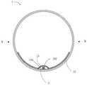
图1是本发明实施例LED日光灯的立体图;1 is a perspective view of an LED fluorescent lamp according to an embodiment of the present invention;
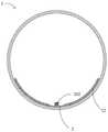
图2是本发明实施例LED日光灯的立体分解图;2 is a perspective exploded view of an LED fluorescent lamp according to an embodiment of the present invention;
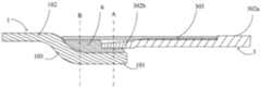
图3示出了本发明实施例LED日光灯中灯管的端部结构;Fig. 3 shows the end structure of the lamp tube in the LED fluorescent lamp according to the embodiment of the present invention;
图4是本发明实施例LED日光灯中灯头的结构一,其中示出了灯头外部的结构;Fig. 4 is the
图5是本发明实施例LED日光灯中灯头的结构二,其中示出了灯头内部的结构;FIG. 5 is the second structure of the lamp cap in the LED fluorescent lamp according to the embodiment of the present invention, which shows the internal structure of the lamp cap;
图6示出了本发明实施例LED日光灯中电源的结构;Fig. 6 shows the structure of the power supply in the LED fluorescent lamp according to the embodiment of the present invention;
图7示出了本发明实施例LED日光灯中灯头和灯管的连接位置的结构;FIG. 7 shows the structure of the connection position of the lamp cap and the lamp tube in the LED fluorescent lamp according to the embodiment of the present invention;
图8示出了作为本发明实施例的变形例中,全塑料灯头(内有导磁金属件和热熔胶) 和灯管透过感应线圈加热固化的示意图;FIG. 8 shows a schematic diagram of an all-plastic lamp cap (with magnetic conductive metal parts and hot melt glue) and a lamp tube being heated and cured through an induction coil in a modification of the embodiment of the present invention;
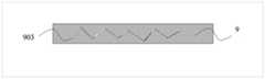
图9是图8的全塑料灯头(内有导磁金属件与热熔胶)的立体剖视图;FIG. 9 is a three-dimensional cross-sectional view of the all-plastic lamp cap (with magnetic conductive metal parts and hot melt adhesive) of FIG. 8;
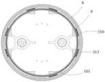
图10示出了全塑料灯头中,绝缘管的内周面上具有一支撑部及一凸部的立体结构图;Fig. 10 shows a three-dimensional structural view of an all-plastic lamp holder with a support portion and a convex portion on the inner peripheral surface of the insulating tube;
图11是图10中沿X-X方向的剖视图;Figure 11 is a cross-sectional view along the X-X direction in Figure 10;
图12示出了沿径向方向看,导磁金属件具有至少一空孔结构的示意图;Fig. 12 shows a schematic view of the magnetic conductive metal member having at least one hole structure viewed from the radial direction;
图13示出了沿径向方向看,导磁金属件具有至少一压痕结构的示意图;Fig. 13 shows a schematic view of the magnetic conductive metal piece having at least one indentation structure viewed from the radial direction;
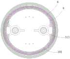
图14示出了图10的绝缘管和灯管结合后,沿灯管轴向方向的剖视图,其中导磁金属件为正圆环形结构;Fig. 14 shows a cross-sectional view along the axial direction of the lamp tube after the insulating tube and the lamp tube of Fig. 10 are combined, wherein the magnetic conductive metal member is a perfect circular ring structure;
图15示出了导磁金属件为一非正圆形环结构时,沿灯管轴向方向的剖视图;Fig. 15 shows a cross-sectional view along the axial direction of the lamp tube when the magnetic conductive metal member is a non-circular ring structure;
图16示出了LED日光灯中可挠式电路板爬过强化部处与电源输出端焊接连接的结构;Fig. 16 shows the structure in which the flexible circuit board climbs over the reinforcement part in the LED fluorescent lamp and is welded and connected to the output end of the power supply;
图17示出了双层可挠式电路板的层结构;FIG. 17 shows the layer structure of the double-layer flexible circuit board;
图18是本发明实施例LED日光灯中的灯管沿轴向方向的剖视图;18 is a cross-sectional view of the lamp tube in the LED fluorescent lamp according to the embodiment of the present invention along the axial direction;
图19示出了图18的第一个变形例具反射膜和灯板一侧接触沿轴向方向的剖视图;Fig. 19 shows a cross-sectional view along the axial direction of the first modification of Fig. 18 with the reflective film and the side of the lamp board in contact;
图20是图18的第二个变形例中灯管沿轴向方向的剖视图;FIG. 20 is a cross-sectional view of the lamp tube along the axial direction in the second modification of FIG. 18;
图21示出了图18的第三个变形例中灯管沿轴向方向的剖视图;Fig. 21 shows a cross-sectional view of the lamp tube along the axial direction in the third modification of Fig. 18;
图22是图18的第四个变形例中灯管沿轴向方向的剖视图;Fig. 22 is a cross-sectional view of the lamp tube along the axial direction in the fourth modification of Fig. 18;
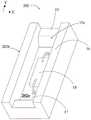
图23示出了本发明实施例LED日光灯的光源中支架的立体结构图。FIG. 23 shows a perspective structural view of a bracket in a light source of an LED fluorescent lamp according to an embodiment of the present invention.
具体实施方式Detailed ways
本发明的发明人经过创造性劳动,在玻璃灯管的基础上,提出了一种新的LED日光灯,以解决背景技术中提到的问题以及上述问题。Through creative work, the inventor of the present invention proposes a new LED fluorescent lamp based on a glass lamp tube to solve the problems mentioned in the background art and the above problems.
为使本发明的上述目的、特征和优点能够更为明显易懂,下面结合附图对本发明的具体实施例做详细的说明。In order to make the above objects, features and advantages of the present invention more clearly understood, the specific embodiments of the present invention will be described in detail below with reference to the accompanying drawings.
本发明实施例提供一种LED日光灯,参照图1-2,包括:灯管1、设于灯管1内的灯板2,以及分别设于灯管1两端的两个灯头3。其中灯管1可以采用塑料灯管或者玻璃灯管,本实施例采用具有强化部的玻璃灯管,以避免传统玻璃灯管易破裂以及破裂因漏电而引发的触电事故,以及塑料灯管容易老化的问题。An embodiment of the present invention provides an LED fluorescent lamp, referring to FIGS. 1-2 , comprising: a
灯管强化的方式可以使用化学方式或是物理方式对玻璃做二次加工强化,化学方式的基本原理是用改变玻璃表面的组成来提高玻璃的强度,其方法是的用其它碱金属离子与玻璃表层的Na离子或K离子发生交换,表面形成离子交换层,当冷却到常温后,玻璃处于内层受拉,外层受压的状态,从而达到增加强度的目的,包括但不限于高温型离子交换法、低温型离子交换法、脱碱法、表面结晶法、硅酸钠强化法等。The way of strengthening the lamp tube can use chemical methods or physical methods to strengthen the glass by secondary processing. The basic principle of the chemical method is to improve the strength of the glass by changing the composition of the glass surface. The method is to use other alkali metal ions and glass. The Na ions or K ions on the surface are exchanged, and an ion exchange layer is formed on the surface. After cooling to normal temperature, the glass is in a state where the inner layer is stretched and the outer layer is compressed, so as to achieve the purpose of increasing the strength, including but not limited to high-temperature ions Exchange method, low temperature ion exchange method, dealkalization method, surface crystallization method, sodium silicate strengthening method, etc.
1、高温型离子交换法1. High temperature ion exchange method
在玻璃的软化点与转变点之间的温度区域内,把含Na2O或K2O的玻璃侵入锂的熔盐中,使玻璃中的Na离子或与它们半径小的熔盐中的Li离子相交换,然后冷却至室温,由于含Li离子的表层与含Na离子或K离子内层膨胀系数不同,表面产生残余压力而强化,同时;玻璃中和含有Al2O3、TiO2等成分时,通过离子交换,能产生膨胀系数极低的结晶,冷却后的玻璃表面将产生很大的压力,可得到强度高达700MPa的玻璃。In the temperature region between the softening point and the transition point of the glass, the glass containing Na2 O or K2 O is intruded into the molten salt of lithium, so that the Na ions in the glass or the Li in the molten salt with their small radius Ion phase exchange, and then cooled to room temperature. Due to the difference in the expansion coefficient between the surface layer containing Liions and the inner layer containing Naions or Kions , the surface is strengthened by residual pressure. When ion exchange is used, crystals with extremely low expansion coefficients can be produced, and the surface of the glass after cooling will generate a lot of pressure, and glass with a strength of up to 700MPa can be obtained.
2、低温型离子交换法2. Low temperature ion exchange method
低温离子交换法在比玻璃应变点低的温度区,用比表层碱离子(如Na离子)还大一些离子半径的一价阳离子(如K离子)与Na离子做离子交换,使K离子进入表层的方法。例如Na2O+CaO+SiO2系统玻璃,在四百多度的熔融盐中可以浸渍十几小时。Low-temperature ion exchange method In the temperature region lower than the glass strain point, a monovalent cation (such as K ion) with a larger ionic radius than the surface alkali ion (such as Na ion) is used for ion exchange with Na ion, so that K ion enters the surface layer. Methods. For example, Na2 O+CaO+SiO2 system glass can be immersed in molten salt of more than 400 degrees for more than ten hours.
3、脱碱法3. Dealkalization
脱碱法是在含亚硫酸气体与水分的高温气氛中,利用Pt催化剂处理玻璃,使Na+离子从玻璃表层渗出与亚硫酸反应,从而表面层成为富SiO2层,其结果由于表层成为低膨胀性玻璃,冷却时产生压应力The dealkalization method is to treat the glass with a Pt catalyst in a high-temperature atmosphere containing sulfurous acid gas and water, so that Na+ ions are exuded from the surface layer of the glass and react with sulfurous acid, so that the surface layer becomes aSiO2 -rich layer. As a result, the surface layer becomes low. Expandable glass, compressive stress upon cooling
4、表面结晶法4. Surface crystallization method
表面结晶法与高温型离子交换不同的,但仅通过热处理在表层形成低膨胀系数的微晶体,从而使之强化的方法。The surface crystallization method is different from the high temperature type ion exchange, but only by heat treatment to form microcrystals with a low expansion coefficient in the surface layer to strengthen them.
5、硅酸钠强化法5. Sodium silicate strengthening method
硅酸钠强化法是将硅酸钠(水玻璃)的水溶液中在100摄氏度以上数个大气压下处理,从而得到难以划伤表层的高强度玻璃。The sodium silicate strengthening method is to treat the aqueous solution of sodium silicate (water glass) at several atmospheric pressures above 100 degrees Celsius, so as to obtain high-strength glass that is difficult to scratch the surface layer.
本实施例以结构强化设计做说明,灯管1包括主体102和分别位于主体102两端的端部101,灯头3套设于端部101外。其中,至少一个端部101的外径小于主体102的外径。本实施例中,设置两个端部101的外径均小于主体102的外径。具体地,灯管1的两端通过强化部处理,端部101形成强化部结构,灯头3套在强化后的端部101上,这样可以使得灯头3外径与灯管主体102外径的差值变小,甚至完全相平,即灯头3外径与主体102 外径相等。这样设置的好处在于,在运输过程中,包装承托物不会只接触灯头3,其能够同时接触灯头3和灯管1,使得整支LED日光灯受力均匀,而不会使得灯头3成为唯一受力点,避免灯头3与灯管端部101连接的部位由于受力集中发生破裂,提高产品的质量,并兼具美观的作用。In this embodiment, the structural strengthening design is used as an illustration. The
本实施例中,灯头3外径与主体102外径基本相等,公差为在正负0.2mm(毫米)内,最多不超过正负1mm。In this embodiment, the outer diameter of the
为了达到灯头3外径与主体102外径基本相等的目的,根据不同的灯头3的厚度,强化后的端部101与主体102外径的差值范围可以为1mm~10mm;或者更优选的,强化后的端部101与主体102外径的差值范围可以放宽至2mm~7mm。In order to achieve the purpose that the outer diameter of the
本实施例中,参照图3,灯管1的端部101与主体102之间平滑过渡,形成一个过渡部103,过渡部103呈弧面,即过渡部103沿轴向的剖面呈弧线状。In this embodiment, referring to FIG. 3 , the
过渡部103的长度为1mm~4mm,如果小于1mm,则过渡部的强度不够;如果大于4mm,则会减小主体102的长度,减小发光面,同时需要灯头3的长度相应增加以与主体102配合,造成灯头3的材料增加。在其他实施例中,则过渡部103也可以不为弧形。The length of the
以T8的标准灯管为例,强化后的端部101的外径范围为20.9mm~23mm,如果小于20.9mm,则端部101的内径过小,导致电源部件无法插入灯管1中。主体102的外径范围为25mm~28mm,如果小于25mm,则以现有的工艺条件,不方便对其两端作强化部处理,如果大于28mm,将不符合行业标准。Taking a T8 standard lamp tube as an example, the outer diameter of the reinforced
继续参照图2,灯板2上设有若干光源202,灯头3内设有电源5,光源202与电源5 之间通过灯板2电气连通。Continuing to refer to FIG. 2 , the
其中,电源5可以为单个体(即所有电源组件都集成在一个部件中),并设于灯管1一端的灯头3中;或者电源5也可以分为两部分,称为双个体(即所有电源组件分别设置在两个部件中),并将两部分分别设于灯管两端的灯头3中。如果灯管1仅有一端作强化部处理时,电源优先选择为单个体,并设于强化后的端部101所对应的灯头3中。Wherein, the
不管是单个体还是双个体,电源的形成方式都可以有多重选择,例如,电源可以为一种灌封成型后的模块,具体地,使用一种高导热的硅胶(导热系数≥0.7w/m·k),通过模具对电源组件进行灌封成型,得到电源,这种方式得到的电源具有高绝缘、高散热、外形更规则的优点,且能够方便地与其他结构件配合。或者,电源也可以为不作灌封胶成型,直接将裸露的电源组件置入灯头内部,或者将裸露的电源组件用传统热缩管包住后,再置入灯头3内部。Whether it is a single body or a double body, there are multiple options for the formation of the power supply. For example, the power supply can be a module after potting and molding. Specifically, a high thermal conductivity silica gel (thermal conductivity ≥ 0.7w/m) is used. k), the power supply is obtained by potting and molding the power supply components through a mold. The power supply obtained in this way has the advantages of high insulation, high heat dissipation, and more regular shape, and can be easily matched with other structural parts. Alternatively, the power supply can also be formed without potting glue, and the exposed power supply components can be directly placed inside the lamp head, or the exposed power supply components can be wrapped with traditional heat shrinkable tubes, and then placed inside the
一般来说,参照图2并结合图4-6,电源5的一端具有公插501,另一端具有金属插针502,灯板2的端部设有母插201,灯头3上设有用于连接外部电源的空心导电针301。电源5的公插501插设于灯板2的母插201内,金属插针502插设于灯头3的空心导电针301 内。此时公插501和母插201相当于转接头,用于将电源5和灯板2电连接。当金属插针 502插入空心导电针301内后,经过外部冲压工具冲击空心导电针301,使得空心导电针 301发生轻微的变形,从而固定住电源5上的金属插针502,并实现电气连接。Generally speaking, referring to FIG. 2 and in conjunction with FIGS. 4-6 , one end of the
通电时,电流依次通过空心导电针301、金属插针502、公插501以及母插201到达灯板2,并通过灯板2到达光源202。在其他实施例中,可以不采用公插501、母插201的连接方式,而可以用传统导线打线方式取代,即采用一根传统的金属导线,将金属导线的一端与电源电连接,另一端与灯板2电连接,但导线打线连接的方式有可能在在运输过程中会有断裂的问题,质量上稍差。When energized, the current reaches the
为了方便灯头3与灯管1的连接固定,本实施例针对灯头3做了改进。In order to facilitate the connection and fixation of the
参照图4-5并结合图7-9,灯头3套设于灯管1外时,灯头3套设于端部101外,并延伸至过渡部103,与过渡部103部分重叠。4-5 in conjunction with FIGS. 7-9 , when the
灯头3除了空心导电针301之外,还包括绝缘管302,以及固设于绝缘管302外周面上的导热部303,其中空心导电针301设于绝缘管302上。导热部303的一端伸出绝缘管 302面向灯管的一端,导热部303的伸出部分(伸出绝缘管的部分)和灯管1之间通过热熔胶6粘接。本实施例中,灯头3通过导热部303延伸至过渡部103,绝缘管302面向灯管1的一端未延伸至过渡部103,即绝缘管302面向灯管的一端与过渡部103之间具有间隔。在本实施例中,绝缘管302主要是在一般状态下不是电的良导体即可,并不限定使用材质为塑料、陶瓷等材质。In addition to the hollow
热熔胶6(包含一种俗称为焊泥粉的材料)成份较佳的为:酚醛树脂2127#、虫胶、松香、方解石粉、氧化锌、乙醇等。这种热熔胶6能够在高温加热的条件下,改变其物理状态发生大幅膨胀,达到固化的效果,加上本身材料的黏性,从而可以使灯头3与灯管1 紧密接触,便于LED日光灯实现自动化生产。于本实施例中,热熔胶6在高温加热后会呈现膨胀并流动,随后冷却即会达到固化的效果,当然,本发明热熔胶成份的选用并不限定于此,亦可选用高温加热至预定温度后而固化的成份。由于本发明热熔胶6不会由于电源组件等发热元器件发热形成高温环境而导致可靠性下降,可以防止LED日光灯使用过程中灯管1与灯头3的粘接性能降低,提高长期可靠性。The components of the hot melt adhesive 6 (including a material commonly known as welding mud powder) are preferably: phenolic resin 2127#, shellac, rosin, calcite powder, zinc oxide, ethanol, and the like. This kind of hot melt adhesive 6 can change its physical state and expand greatly under the condition of high temperature heating to achieve the effect of curing, plus the viscosity of its own material, so that the
具体地,在导热部303伸出部分的内周面与灯管1的外周面之间形成有一容置空间,热熔胶6填充于该容置空间中(图7中虚线B所示位置)。换言之,热熔胶6填充的位置借由与灯管1轴向垂直的第一虚拟平面(如图7中虚线B所画过的平面)通过:沿径向向内的方向,在第一虚拟平面的位置,依序排列为导热部303、热熔胶6和灯管1的外周面。热熔胶6涂覆厚度可以为0.2mm~0.5mm,热熔胶6会膨胀后固化,从而与灯管1接触并将灯头3固定于灯管1。并由于端部101和主体102两者的外周面之间具有高度差,因此可以避免热熔胶溢出到灯管的主体102部分上,免去后续的人工擦拭过程,提高LED日光灯的产量。Specifically, an accommodating space is formed between the inner peripheral surface of the protruding portion of the heat-conducting
加工时,通过外部加热设备将热量传导至导热部303,然后再传导至热熔胶6、使热熔胶6膨胀后固化,从而将灯头3固定粘接在灯管1上。During processing, the heat is conducted to the heat-conducting
本实施例中,如图7,绝缘管302包括沿轴向相接的第一管302a和第二管302b,第二管302b的外径小于第一管302a的外径,两个管的外径差值范围为0.15mm~0.3mm。导热部303设于第二管302b的外周面上,导热部303的外表面与第一管302a的外周面平齐,使得灯头3的外表面平整光滑,保证整个LED日光灯在包装、运输过程中受力均匀。其中,导热部303沿灯头轴向方向的长度与绝缘管302的轴向长度比为1:2.5~1:5,即导热部长度:绝缘管长度为1:2.5~1:5。In this embodiment, as shown in FIG. 7 , the insulating
在本实施例中,为了确保粘接的牢固性,本实施例设置第二管302b至少部分套设于灯管1外,容置空间还包括第二管302b的内表面和灯管的端部101外表面之间的空间。热熔胶6有部分填充于相互重叠(图7中虚线A所示位置)的第二管302b和灯管1之间,即部分热熔胶6位于第二管302b的内表面和端部101的外表面之间。换言之,热熔胶6 填充于所述容置空间的位置借由一与灯管轴向垂直的第二虚拟平面(如图7中虚线A所画过的平面)通过:沿径向向内的方向,在第二虚拟平面的位置,依序排列为导热部303、第二管302b、热熔胶6及端部101。特予说明的是,于本实施例中,热熔胶6并不需要完全填满上述的容置空间(如图中容置空间还可以包括导热部303与第二管302b之间的空间)。制造时,当在导热部303和端部101之间涂覆热熔胶6时,可以适当增加热熔胶的量,使得在后续加热的过程中,热熔胶能够由于膨胀而流动至第二管302b和端部101之间,固化后进而将两者粘合连接。In this embodiment, in order to ensure the firmness of the bonding, in this embodiment, the
其中,灯管1的端部101插设于灯头3后,灯管1的端部101插入灯头3部分的轴向长度占导热部303轴向长度的三分之一到三分之二之间,这样的好处是:一方面,保证空心导电针301与导热部303具有足够的爬电距离,通电时两者不易短接使人触电而引发危险;另一方面,由于绝缘管302的绝缘作用,使得空心导电针301与导热部303之间的爬电距离加大,更容易通过高电压时使人触电而引发危险的测试。Wherein, after the
进一步地,对于第二管302b内表面的热熔胶6来说,第二管302b隔在热熔胶6与导热部303之间,因此热量从导热部303传导至热熔胶6的效果会打折扣。因此,参照图5,本实施例在第二管302b面向灯管1的一端(即远离第一管302a的一端)设置多个缺口302c,增加导热部303与热熔胶6的接触面积,以利于热量快速从导热部303传导至热熔胶6上,加速热熔胶6的固化过程。同时,当用户触及导热部303时,由于导热部303和灯管1之间热熔胶6的绝缘作用,不会因为灯管1有破损而触电。Further, for the hot melt adhesive 6 on the inner surface of the
其中,导热部303可以为各种容易传导热量的材料,本实施例中为金属片,并兼具美观的考虑,例如铝合金。导热部303呈管状(或称环状),套设在第二管302b外。绝缘管 302可以为各种绝缘材料,但以不容易导热为佳,避免热量传导至灯头3内部的电源组件上、影响电源组件的性能,本实施例中的绝缘管302为塑料管。Wherein, the heat-conducting
在其他实施例中,导热部303还可以由多个沿第二管302b周向间隔或者不间隔排列的金属片组成。In other embodiments, the heat-conducting
在其他实施例中,灯头还可以设置成其他形式,例如:In other embodiments, the lamp cap can also be set in other forms, such as:
参照图8-9所示,灯头3除包括绝缘管302外,还包括导磁金属件9,不包含导热部。导磁金属件9固设在绝缘管302的内周面上,且至少部分位于绝缘管302的内周面和灯管端部之间、与灯管1沿径向具有重叠部分。Referring to FIGS. 8-9 , in addition to the insulating
本实施例中,整个导磁金属件9都位于绝缘管302内,热熔胶6涂覆于导磁金属件9的内表面上(导磁金属件9面向灯管1的表面),并与灯管1的外周面粘接。其中,为了增加粘接面积、提高粘接稳定性,热熔胶6覆盖导磁金属件9的整个内表面。In this embodiment, the entire magnetic
制造时,将绝缘管302插设于一感应线圈11中,使得感应线圈11与导磁金属件9沿绝缘管302的径向相对。加工时,将感应线圈11通电,感应线圈11通电后形成电磁场,并电磁场碰到导磁金属件9后转换为电流,使得导磁金属件9发热,即运用电磁感应技术使得导磁金属件9发热,并热量传导至热熔胶6,热熔胶6吸收热量后膨胀并流动,随后冷却使得热熔胶6固化,以实现将灯头3固定于灯管1的目的。感应线圈11尽量与绝缘管 302同轴,使得能量传递较为均匀。本实施例中,感应线圈11与绝缘管302中轴线之间的偏差不超过0.05mm。当粘接完成后,将灯管1抽离感应线圈11。本实施例中,热熔胶6 在吸收热量后会呈现膨胀并流动,随后冷却即会达到固化的效果,当然,本发明热熔胶成份的选用并不限定于此,亦可选用吸收热量后而固化的成份。During manufacture, the insulating
其中,为了较好地支撑导磁金属件9,绝缘管302的内周面用于支撑导磁金属件9的部位302d的内径要大于其余部分302e的内径,并形成一个台阶,导磁金属件9的轴向一端顶靠在台阶上,并且使得设置导磁金属件9后,整个灯头的内表面平齐。另外,导磁金属件9可以是各种形状,例如呈周向排列的片状或管状等,此处设置导磁金属件9呈与绝缘管302同轴的管状。Among them, in order to better support the magnetic
在其他实施例中,绝缘管302的内周面用于支撑导磁金属件9的部位还可以为如下形式:参照图10、图11,绝缘管302的内周面上具有朝向绝缘管302内部突伸的支撑部313,并且,绝缘管302的内周面上、在支撑部313面向灯管主体一侧还设置有凸部310,所述凸部310的径向厚度小于所述支撑部313的径向厚度。如图11,本实施例的凸部310与支撑部313沿轴向相连,导磁金属件9在轴向上顶靠在支撑部313的上缘(即支撑部面向凸部一侧的端面),在周向上顶靠在凸部310的径向内侧。也就是说,至少一部分凸部310 位于导磁金属件9和绝缘管302的内周面之间。其中,凸部310可以是沿绝缘管302周向延伸的环形、或者是绕着绝缘管302的内周面沿周向间隔排列的多个凸块,换言之,凸块的排列可以呈周向等距离间隔排列或是不等距离间隔排列,只要能够使导磁金属件9的外表面和绝缘管302的内周面的接触面积减少,但又能达到固持热熔胶6的功能。In other embodiments, the portion on the inner peripheral surface of the insulating
所述支撑部313由绝缘管302的内周面向内侧凸起的厚度为1mm~2mm,凸部310的厚度小于所述支撑部313厚度,所述凸部310的厚度为0.2mm~1mm。The thickness of the supporting
在其他实施例中,灯头3还可以做成全金属的,此时需要在空心导电针的下部增设一绝缘体,以耐高压In other embodiments, the
在其他实施例中,参照图12,其中图12为导磁金属件9沿径向方向的视图,导磁金属件9面向所述绝缘管的表面具有至少一空孔结构901,空孔结构901的形状为圆形,但不限于圆形,可以例如为椭圆形、方形、星形等,只要能够减少导磁金属件9和绝缘管302 的内周面的接触面积,但又能达到热固化即热熔胶6的功能。较佳地,空孔结构901面积占导磁金属件9面积的10%~50%。空孔结构901的排列可以呈周向等距离间隔排列或是不等距离间隔排列等。In other embodiments, refer to FIG. 12 , which is a view of the magnetic
在其他实施例中,参照图13,导磁金属件9面向所述绝缘管的表面具有一压痕结构903,其中图13为导磁金属件9沿径向方向的视图,压痕结构903可以为从导磁金属件9 的内表面向外表面浮凸的结构,但也可以为从导磁金属件9的外表面向内表面浮凸的结构,其目的是为了在导磁金属面9的外表面形成凸起或凹陷,以达到减小使导磁金属件9的外表面和绝缘管302的内周面的接触面积的目的。但需要注意的是,同时应当保证导磁金属件9与灯管稳定粘接,达到热固化热熔胶6的功能。In other embodiments, referring to FIG. 13 , the surface of the magnetic
本实施例中,参照图14,导磁金属件9为一正圆形环。在其他实施例中,参照图15,导磁金属件9为一非正圆形环,例如但不限于椭圆形环,当灯管1和灯头3为椭圆形时,椭圆形环的短轴略大于灯管端部外径,以减小导磁金属件9的外表面和绝缘管302的内周面的接触面积,但又能达到热固化热熔胶6的功能。换言之,绝缘管302的内周面上具有支撑部313,非正圆形环的导磁金属件9设于支撑部上,因此,可以使导磁金属件9和绝缘管302的内周面的接触面积减少,并又能达到固化热熔胶6的功能。In this embodiment, referring to FIG. 14 , the magnetic
继续参照图2,本实施例的LED日光灯还包括粘接剂4、灯板绝缘胶7和光源胶8。灯板2通过粘接剂4粘贴于灯管1的内周面上。图中所示,粘接剂4可以为硅胶,其形式不限,可以是图中所示的几段,或者呈长条状的一段。Continuing to refer to FIG. 2 , the LED fluorescent lamp of this embodiment further includes an adhesive 4 , a lamp board insulating glue 7 and a light source glue 8 . The
灯板绝缘胶7涂于灯板2面向光源202的表面上,使得灯板2不外露,从而起到将灯板2与外界隔离的绝缘作用。涂胶时预留出与光源202对应的通孔701,光源202设于通孔701中。灯板绝缘胶7的组成成分包括乙烯基聚硅氧烷、氢基聚硅氧烷和氧化铝。灯板绝缘胶7的厚度范围为100μm~140μm(微米)。如果小于100μm,则起不到足够的绝缘作用,如果大于140μm,则会造成材料的浪费。The lamp board insulating glue 7 is coated on the surface of the
光源胶8涂于光源202的表面。光源胶8的颜色为透明色,以保证透光率。涂覆至光源202表面后,光源胶8的形状可以为颗粒状、条状或片状。其中,光源胶8的参数有折射率、厚度等。光源胶8的折射率允许的范围为1.22~1.6,如果光源胶8的折射率为光源 202壳体折射率的开根号,或者光源胶8的折射率为光源202壳体折射率的开根号的正负 15%,则透光率较好。这里的光源壳体是指容纳LED晶粒(或芯片)的壳体。本实施例中光源胶8的折射率范围为1.225~1.253。光源胶8允许的厚度范围为1.1mm~1.3mm,如果小于1.1mm,将会盖不住光源202,效果不佳,如果大于1.3mm,则会降低透光率,同时还会增加材料成本。The light source glue 8 is coated on the surface of the
装配时,先将光源胶8涂于光源202的表面;然后将灯板绝缘胶7涂于灯板2上的一侧表面上;再把光源202固定于灯板2上;接着将灯板2与光源202相背的一侧表面通过粘接剂4粘贴固定于灯管1的内周面;最后再将灯头3固定于灯管1的端部,同时将光源202与电源5电连接。或者是如图16利用可挠式电路板爬过过渡部103和电源焊接 (即穿过过渡部103与电源5焊接),或者采取传统导线打线的方式让灯板2与电源5电性相连,最后灯头3通过图7(用图4-5的结构)或图8(用图9的结构)的方式接在强化部处的过渡部103,形成一个完整的LED日光灯。When assembling, first apply the light source glue 8 on the surface of the
本实施例中,灯板2通过粘接剂4固定在灯管1的内周面,使得光源202贴设在灯管1的内周面上,这样可以增大整支LED日光灯的发光角度,扩大可视角,这样设置一般可以使得可视角可以超过330度。通过在灯板2涂灯板绝缘胶7,在光源202上涂绝缘的光源胶8,实现对整个灯板2的绝缘处理,这样,即使灯管1破裂,也不会发生触电事故,提高安全性。In this embodiment, the
进一步地,灯板2可以是条状铝基板、FR4板或者可挠式电路板中的任意一种。由于本实施例的灯管1为玻璃灯管,如果灯板2采用刚性的条状铝基板或者FR4板,那么当灯管破裂,例如断成两截后,整个灯管仍旧能够保持为直管的状态,这时用户有可能会认为 LED日光灯还可以使用、并去自行安装,容易导致触电事故。由于可挠式电路板具有较强的可挠性与易弯曲的特性,解决刚性条状铝基板、FR4板可挠性与弯曲性不足的情况,因此本实施例的灯板2采用可挠式电路板,这样当灯管1破裂后,灯管1破裂后即无法支撑破裂的灯管1继续保持为直管状态,以告知用户LED日光灯已经不能使用,避免触电事故的发生。因此,当采用可挠式电路板后,可以在一定程度上缓解由于玻璃管破碎而造成的触点问题。以下实施例即以可挠式电路板作为本发明的灯板2来做说明。Further, the
其中,可挠式电路板与电源5的输出端之间可以通过导线打线连接,或者透过公插501、母插201连接,或者,通过焊接连接。与前述灯板2的固定方式一致,可挠式电路板的一侧表面通过粘接剂4粘接固定于灯管1的内周面,而可挠式电路板的两端可以选择固定或者不固定在灯管1的内周面上。The flexible circuit board and the output end of the
如果可挠式电路板的两端不固定在灯管1的内周面上,如果采用导线连接,在后续搬动过程中,由于两端自由,在后续的搬动过程中容易发生晃动,因而有可能使得导线发生断裂。因此可挠式电路板与电源的连接方式优先选择为焊接,具体地,参照图16,可以直接将可挠式电路板爬过强化部结构的过渡部103后焊接于电源5的输出端上,免去导线的使用,提高产品质量的稳定性。此时可挠式电路板不需要设置母插201,电源5的输出端也不需要设置公插501,具体作法可以是将电源5的输出端留出焊盘a,并在焊盘a上留锡、以使得焊盘上的锡的厚度增加,方便焊接,相应的,在可挠式电路板的端部上也留出焊盘 b,并将电源输出端的焊盘a与可挠式电路板的焊盘b焊接在一起。If the two ends of the flexible circuit board are not fixed on the inner peripheral surface of the
可挠式电路板的焊盘b具有两个不连接的焊垫,分别和光源202正负极电连接。在其他实施例中,为了能达到兼容性及后续使用上的扩充性,焊盘b的数量可以具有两个以上的焊垫,例如3个、4个或是4个以上,当焊垫为3个时,第3个焊垫可以用作接地使用,当焊垫为4个时,第4个焊垫可以用来作讯号输入端。相应的,焊盘a亦留有和焊盘b数量相同的焊垫。当焊垫为3个以上时,焊垫间的排列可以为一列并排或是排成两列,依实际使用时的容置面积大小配置在适当的位置,只要彼此不电连接造成短路即可。在其他实施例中,若是将部份电路制作在可挠式电路板上,焊盘b可以只具有单独一个焊垫,焊垫数量愈少,在工艺上愈节省流程;焊垫数量愈多,可挠式电路板和电源输出端的电连接固定愈增强。The pad b of the flexible circuit board has two unconnected pads, which are respectively electrically connected to the positive and negative electrodes of the
在其他实施例中,焊盘b焊垫的内部可以具有穿孔,焊盘a与可挠式电路板的焊盘b焊接在一起时,焊接用的锡可以穿过所述的穿孔,当锡穿出穿孔时,会堆积在穿孔周围,当冷却后,会形成具有大于穿孔直径的焊球,这个焊球结构会起到像是钉子的功能,除了透过焊盘a和焊盘b之间的锡固定外,更可以因为焊球的作用形成结构性的电连接固定增强。In other embodiments, the pad b may have a through hole inside the pad, and when the pad a and the pad b of the flexible circuit board are soldered together, the tin used for soldering may pass through the through hole, and when the tin passes through the pad b. When the perforation is made, it will accumulate around the perforation. After cooling, solder balls with a diameter larger than that of the perforation will be formed. This solder ball structure will function like a nail In addition to tin fixation, structural electrical connection and fixation enhancement can be formed due to the action of solder balls.
在其他实施例中,焊垫的穿孔是在边缘,也就是焊垫具有一缺口,焊接用的锡透过所述的缺口把焊盘a和焊盘b电连接固定,锡会堆积在穿孔周围,当冷却后,会形成具有大于穿孔直径的焊球,这个焊球结构会形成结构性的电连接固定增强,本实施例中,因为缺口的设计,焊接用的锡起到像是ㄇ形钉子的功能。In other embodiments, the through hole of the solder pad is at the edge, that is, the solder pad has a gap, and the solder used for soldering passes through the gap to electrically connect and fix the pad a and the pad b, and the tin will accumulate around the through hole , after cooling, a solder ball with a diameter larger than the through hole will be formed, and this solder ball structure will form a structural electrical connection and fixation enhancement. In this embodiment, because of the design of the gap, the tin used for soldering acts like a ㄇ-shaped nail function.
焊垫的穿孔不论是先形成好,或是在焊接的过程中直接用压焊头打穿,都可以达到本实施例所述的结构。所述的压焊头其与焊锡接触的表面可以为平面或是具有凹部和凸部的表面,凸部可以为长条状或是网格状,所述的凸部不完全将穿孔覆盖,确保焊锡能从穿孔穿出,当焊锡穿出穿孔堆积在穿孔周围时,凹部能提供焊球的容置位置。在其他实施例中,可挠式电路板具有一定位孔,在焊接时可以透过定位孔将焊盘a和焊盘b的焊垫精准的定位。The structure described in this embodiment can be achieved whether the perforation of the pad is formed first, or directly punched by a pressure welding head during the welding process. The surface of the pressure welding head that is in contact with the solder can be a plane or a surface with concave parts and convex parts, and the convex parts can be elongated or grid-shaped. Solder can pass out of the through holes, and the recesses can provide accommodating positions for solder balls when the solder passes through the through holes and accumulates around the through holes. In other embodiments, the flexible circuit board has a positioning hole, and the bonding pads of the pad a and the pad b can be accurately positioned through the positioning hole during soldering.
上述实施例中,可挠式电路板大部分固定在灯管1的内周面上,只有在两端是不固定在灯管1的内周面上,不固定在灯管1内周面上的可挠式电路板形成一自由部,在装配时,自由部和电源焊接的一端会带动自由部向灯管内部收缩,可挠式电路板的自由部会因收缩而变形,使用上述的具有穿孔焊垫的可挠式电路板,可挠式电路板具有光源的一侧和电源焊接的焊盘a是朝向同一侧的,当可挠式电路板的自由部因收缩而变形时,可挠式电路板和电源焊接的一端对电源是有一个侧向的拉力,相较于可挠式电路板具有光源的一侧和电源焊接的焊盘a是朝向不同一侧的焊接法,可挠式电路板和电源焊接的一端对电源还有一个向下的拉力,使用上述的具有穿孔焊垫的可挠式电路板,形成结构性的电连接具有更佳的固定增强效果。In the above-mentioned embodiment, most of the flexible circuit boards are fixed on the inner peripheral surface of the
其中,如图17,可挠式电路板包括一层导电层2a,光源202设于导电层2a上,通过导电层2a与电源电气连通。参照图17,本实施例中,可挠式电路板还可以包括一层介电层2b,与导电层2a叠置,导电层2a在与介电层2b相背的表面用于设置光源202,介电层 2b在与导电层2a相背的表面则通过粘接剂4粘接于灯管1的内周面上。其中,导电层2a 可以是金属层,或者布有导线(例如铜线)的电源层。17, the flexible circuit board includes a layer of
在其他实施例中,导电层2a和介电层2b的外表面可以包覆一电路保护层,所述电路保护层可以是一种油墨材料,具有阻焊和增加反射的功能。或者,可挠式电路板可以是一层结构,即只由一层导电层2a组成,然后在导电层2a的表面包覆一层上述油墨材料的电路保护层。不论是一层导电层2a结构或二层结构(一层导电层2a和一层介电层2b)都可以搭配电路保护层。电路保护层也可以在可挠式电路板的一侧表面设置,例如仅在具有光源202之一侧设置电路保护层。需要注意的是,可挠式电路板为一层导电层结构2a或为二层结构(一层导电层2a和一层介电层2b),明显比一般的三层柔性基板(二层导电层中夹一层介电层)更具可挠性与易弯曲性,因此,可与具有特殊造型的灯管1搭配(例如:非直管灯),而将可挠式电路板紧贴于灯管1管壁上。此外,可挠式电路板紧贴于灯管管壁为较佳的配置,且可挠式电路板的层数越少,则散热效果越好,并且材料成本越低,更环保,柔韧效果也有机会提升。In other embodiments, the outer surfaces of the
当然,本发明的可挠式电路板并不仅限于一层或二层电路板,在其他实施例中,可挠式电路板包括多层导电层2a与多层介电层2b,介电层2b与导电层2a会依序交错叠置且设于导电层2a与光源202相背的一侧,光源202设于多层导电层2a的最上一层,通过导电层2a的最上一层与电源电气连通。Of course, the flexible circuit board of the present invention is not limited to a one-layer or two-layer circuit board. In other embodiments, the flexible circuit board includes a multi-layer
进一步地,灯管1内周面或外周面上覆盖有粘接膜(未图示),用于在灯管1破裂后对灯管1的外部和内部进行隔离。本实施例将粘接膜涂在灯管1的内周面上。Further, the inner peripheral surface or the outer peripheral surface of the
粘接膜的组成成分包括端乙烯基硅油、含氢硅油、二甲苯和碳酸钙。其中端乙烯基硅油的化学式为:(C2H8OSi)n·C2H3,含氢硅油的化学式为:C3H9OSi·(CH4OSi)n·C3H9Si。The composition of the adhesive film includes vinyl terminated silicone oil, hydrogen-containing silicone oil, xylene and calcium carbonate. The chemical formula of the vinyl-terminated silicone oil is: (C2 H8 OSi)n ·C2 H3 , and the chemical formula of the hydrogen-containing silicone oil is: C3 H9 OSi · (CH4 OSi)n ·C3 H9 Si.
其生成产物为聚二甲基硅氧烷(有机硅弹性体),化学式为:The resulting product is polydimethylsiloxane (organosilicon elastomer), and the chemical formula is:

其中二甲苯为辅助性材料,当粘接膜涂覆在灯管1内周面并固化后,二甲苯会挥发掉,其作用主要是调节粘度,进而来调节粘接膜的厚度。Among them, xylene is an auxiliary material. When the adhesive film is coated on the inner peripheral surface of the
本实施例中,由于灯管内部涂有粘接膜,在玻璃灯管破碎后,粘接膜会将碎片粘连一起,并且不会形成贯通灯管内部和外部的通孔,从而防止用户接触到灯管1内部的带电体,以避免发生触电事故,同时采用上述配比的粘接膜还具有扩散光、透光的作用,提高整支 LED日光灯的发光均匀度和透光率。In this embodiment, since the inside of the lamp tube is coated with an adhesive film, after the glass lamp tube is broken, the adhesive film will stick the fragments together, and will not form a through hole penetrating the inside and outside of the lamp tube, thereby preventing the user from touching the The charged body inside the
需要注意的是,由于本实施例中的灯板2为可挠式电路板,因此也可以不设置粘接膜。It should be noted that, since the
为了进一步提高LED日光灯的光效,本实施例还从两个方面对LED日光灯做了改进,分别针对灯管和光源。In order to further improve the light efficiency of the LED fluorescent lamp, the present embodiment further improves the LED fluorescent lamp from two aspects, respectively aiming at the lamp tube and the light source.
(一)对灯管作的改进(1) Improvement of the lamp tube
参照图18,本实施例的灯管1内除了紧贴于灯管1的灯板2(或可挠式电路板)还包括扩散层13,光源202产生的光线通过扩散层13后穿出灯管1。Referring to FIG. 18 , the
扩散层13对光源202发出的光起到扩散的作用,因此,只要能使得光线透过扩散层13后再穿出灯管1,扩散层13的布置可以有多种形式,例如:扩散层13可以涂覆或覆盖于灯管1的内周面上,或者涂覆或覆盖于光源202表面上的扩散涂层(图中未示出),或者作为一个外罩而罩(或遮盖)在光源202外的扩散膜片。The
如图18,扩散层13为扩散膜片,且罩在光源202外,且与光源202不接触。扩散膜片的一般用语是光学扩散片或光学扩散板,通常用PS聚苯乙烯、PMMA聚甲基丙烯酸甲酯、PET(聚对苯二甲酸乙二酯)、PC(聚碳酸酯)中的一种或几种的组合来搭配扩散粒子,所形成的一种复合材料,当光线透过该复合材料时能够发生漫射,可修正光线成均匀面光源以达到光学扩散的效果最终使得从灯管的亮度均匀分布。As shown in FIG. 18 , the
当扩散层13为扩散涂层时,其成分可以包括碳酸钙、磷酸锶中的至少一种。当利用碳酸钙或磷酸锶或这两者混合搭配适当的溶液所形成的扩散涂层,将具有绝佳的扩散和透光(有机会达到90%以上)的效果。另外,透过具有创造力的劳动也发现,结合强化部玻璃的灯头有时候会有质量问题,有些许比例会容易脱落,而只要将该扩散涂层也涂到灯管的端部101的外表面上,扩散涂层和热熔胶6间会增加灯头和灯管间的摩擦力,使得扩散涂层和热熔胶6间的摩擦力大于未涂上扩散涂层时灯管的端部101的端面和热熔胶间的摩擦力,因此灯头3透过扩散涂层和热熔胶6间的摩擦力,灯头3脱落的问题便能大幅度的解决。When the
本实施例中,在调配时,扩散涂层的组成成分包括碳酸钙磷酸锶(例如CMS-5000,白色粉末)、增稠剂(例如增稠剂DV-961,乳白色液体),以及陶瓷活性炭(例如陶瓷活性碳SW-C,无色液体)。其中,增稠剂DV-961的化学名为胶态二氧化硅变性丙烯树脂,其组分包括丙烯酸树脂、硅胶和纯水;陶瓷活性碳SW-C的组分包括丁二酸酯磺酸钠盐、异丙醇和纯水,其中丁二酸酯磺酸钠盐的化学式为:In this example, when formulating, the components of the diffusion coating include calcium carbonate strontium phosphate (such as CMS-5000, white powder), thickener (such as thickener DV-961, milky white liquid), and ceramic activated carbon ( Such as ceramic activated carbon SW-C, colorless liquid). Among them, the chemical name of thickener DV-961 is colloidal silica modified propylene resin, and its components include acrylic resin, silica gel and pure water; the components of ceramic activated carbon SW-C include sodium succinate sulfonate salt, isopropanol, and pure water, wherein the chemical formula for sodium succinate sulfonate is:

具体地,扩散涂层以碳酸钙磷酸锶为主材料,搭配增稠剂,陶瓷活性碳以及去离子水,混合后涂覆于玻璃灯管的内周面上,涂覆的平均厚度落在20~30μm之间,最后去离子水将挥发掉,只剩下碳酸钙、增稠剂与陶瓷活性碳三种物质。采用这种材料形成的扩散层13,可以具有约90%的透光率。另外,这种扩散层13在除了具有扩散光的效果之外,还能起到电隔离的作用,从而使得当玻璃灯管破裂时,降低用户触电的风险;同时,这种扩散层 13可以使得光源202在发光时,让光产生漫射,往四面八方射出,从而能够照到光源202 的后方,即靠近可挠式电路板的一侧,避免在灯管1中形成暗区,提升空间的照明舒适感。Specifically, the diffusion coating is mainly composed of calcium carbonate and strontium phosphate, and is mixed with thickener, ceramic activated carbon and deionized water. After mixing, it is coated on the inner peripheral surface of the glass lamp tube, and the average thickness of the coating is 20 ~30μm, and finally the deionized water will volatilize, leaving only three substances: calcium carbonate, thickener and ceramic activated carbon. The
在其他实施例中,扩散涂层也可以磷酸锶(或者碳酸钙和磷酸锶的混合物)为主材料,搭配增稠剂,陶瓷活性碳以及去离子水,混合后涂覆于玻璃灯管的内周面上,涂覆厚度与本实施例相同。In other embodiments, the diffusion coating can also be made of strontium phosphate (or a mixture of calcium carbonate and strontium phosphate) as the main material, together with a thickener, ceramic activated carbon and deionized water, and then coated on the inside of the glass lamp after mixing. On the peripheral surface, the coating thickness is the same as in this embodiment.
进一步地,继续参照图18,灯管1的内周面上还设有反射膜12,反射膜12设于具有光源202的灯板2周围,且沿周向占用灯管1的部分内周面。如图18所示,反射膜12在灯板2两侧沿灯管周向延伸,灯板2基本位于反射膜12沿周向的中间位置。Further, referring to FIG. 18 , the inner peripheral surface of the
具体地,反射膜12贴设于灯管1的内周面上,并在反射膜12上开设与灯板2对应的开孔12a,开孔12a的尺寸应当与灯板2一致或者略大于灯板2,用于容纳具有光源202 的灯板2。装配时,现将带有光源202的灯板2(或可挠式电路板)设置于灯管1的内周面上,再将反射膜12贴设在灯管内周面,其中反射膜12的开孔12a与灯板2一一对应,以将灯板2暴露在反射膜12之外。Specifically, the
本实施例中,反射膜12的反射率至少要大于85%,反射效果较好,一般在90%以上时,最好能达到95%以上,以获得更为理想的反射效果。反射膜12沿灯管1周向延伸的长度占据整个灯管1圆周的30%~50%,也就是说,沿灯管1的周向方向,反射膜12的周向长度与灯管1内周面的周长之间的比例范围为0.3~0.5。In this embodiment, the reflectivity of the
在前述的图12-14的实施例中,玻璃管的内周面上,可全部都涂上扩散涂层,或者是部分涂上扩散涂层(有反射膜12之处不涂),但无论是哪一种方式,扩散涂层最好都要涂到灯管1的端部的外表面上,以使得灯头3与灯管1之间的黏接更牢固。In the aforementioned embodiments of FIGS. 12-14 , the inner peripheral surface of the glass tube may be entirely coated with a diffusion coating, or may be partially coated with a diffusion coating (where the
(二)对光源作的改进(2) Improvements to the light source
参照图23,光源202可以进一步改良为包括具有凹槽202a的支架202b,以及设于凹槽202a中的LED晶粒18。凹槽202a内填充有荧光粉,荧光粉覆盖LED晶粒18,以起到光色转换的作用。一根灯管1中,光源202具有多个,多个光源202排布成一列或多列,每列光源202沿灯管1的轴向(Y方向)排布。每个支架202b中的凹槽202a可以为一个或者多个。23, the
其中,至少一个光源202的支架202b具有沿灯管长度方向排布的第一侧壁15,以及沿灯管宽度方向排布的第二侧壁16,第一侧壁15低于第二侧壁16。或者,至少一个光源 202的支架202b具有沿灯管长度方向延伸的第二侧壁16,以及沿灯管宽度方向延伸的第一侧壁15,第一侧壁15低于第二侧壁16。此处的第一侧壁、第二侧壁指的是用以围成凹槽202a的侧壁。Wherein, the
本实施例中,每个支架202b具有一个凹槽202a,对应的,每个支架202b具有两个第一侧壁15、两个第二侧壁16。In this embodiment, each
其中,两个第一侧壁15沿灯管1长度方向(Y方向)排布,两个第二侧壁16沿灯管 1宽度方向(X方向)排布。第一侧壁15沿灯管1的宽度方向(X方向)延伸,第二侧壁 16沿灯管1的长度方向(Y方向)延伸,由第一侧壁15和第二侧壁16围成凹槽202a。当用户从灯管的侧面,例如沿X方向观察灯管时,第二侧壁16可以阻挡用户的视线直接看到光源202,以降低颗粒的不舒适感。其中,第一侧壁15“沿灯管1的宽度方向”延伸,只要满足延伸趋势与灯管1的宽度方向基本相同即可,不要求严格与灯管1的宽度方向平行,例如,第一侧壁15可以与灯管1的宽度方向有些许角度差,或者,第一侧壁15也可以为折线形、弧形、波浪形等各种形状;第二侧壁16“沿灯管1的长度方向”延伸,只要满足延伸趋势与灯管1的长度方向基本相同即可,不要求严格与灯管1的长度方向平行,例如,第二侧壁16可以与灯管1的长度方向有些许角度差,或者,第二侧壁16也可以为折线形、弧形、波浪形等各种形状。Wherein, the two
本实施例中,第一侧壁15低于第二侧壁16,可以使得光线能够容易越过支架202b发散出去,透过疏密适中的间距设计,在Y方向可以不产生颗粒的不舒适感,在其他实施例中,若第一侧壁不低于第二侧壁,则每列光源202之间要排列地更紧密,才能降低颗粒感,提高效能。In this embodiment, the
其中,第一侧壁15的内表面15a为坡面,相对于将内表面15a设置为垂直于底壁的形式来说,坡面的设置使得光线更容易穿过坡面发散出去。坡面可以包括平面或弧面,本实施例中采用平面,且该平面的坡度约在30度~60度之间。也就是说,平面与凹槽202a的底壁之间的夹角范围为120度~150度之间。Wherein, the
在其他实施例中,平面的坡度还可以约在15度~75度之间,也就是说,平面与凹槽202a的底壁之间的夹角范围为105度~165度之间。坡面也可以是平面和弧面的结合体。In other embodiments, the slope of the plane may also be approximately between 15 degrees and 75 degrees, that is, the included angle between the plane and the bottom wall of the
需要提醒注意的是,在其他实施例中,对于同一根LED日光灯而言,在“灯管具有强化部结构”、“灯板采用可挠式电路板”、“灯管内周面涂有粘接膜”、“灯管内周面涂有扩散层”、“光源外罩有扩散膜片”、“灯管内壁涂有反射层”、“灯头为包括导热部的灯头”、“灯头为包括导磁金属片的灯头”、“光源具有支架”等特征中,可以只包括其中的一个或多个。It should be reminded that, in other embodiments, for the same LED fluorescent lamp, the “lamp tube has a reinforced part structure”, “the lamp board adopts a flexible circuit board”, “the inner peripheral surface of the lamp tube is coated with adhesive Contact film", "The inner peripheral surface of the lamp is coated with a diffuser layer", "The light source cover has a diffuser film", "The inner wall of the lamp is coated with a reflective layer", "The lamp cap is a lamp cap including a heat conducting part", "The lamp cap is a Among the features such as the lamp cap of the magnetic metal sheet" and "the light source has a bracket", only one or more of them may be included.
在灯管具有强化部结构中,所述灯管包括主体和分别位于所述主体两端的端部,所述端部各套设于一灯头,至少一个所述端部的外径小于所述主体的外径,且对应所述外径小于所述主体外径端部的灯头,其外径与所述主体的外径相等。In the structure of the lamp tube with the strengthening portion, the lamp tube includes a main body and ends respectively located at both ends of the main body, the ends are each sleeved on a lamp cap, and the outer diameter of at least one of the ends is smaller than that of the main body. The outer diameter of the lamp cap corresponding to the outer diameter of the lamp cap is smaller than that of the outer diameter of the main body, and its outer diameter is equal to the outer diameter of the main body.
在灯管内周面涂有扩散层中,所述扩散涂层的组成成分包括碳酸钙、磷酸锶中的至少一种,以及增稠剂和陶瓷活性炭。此外,所述扩散层亦可为扩散膜片且罩在光源外。When the inner peripheral surface of the lamp tube is coated with a diffusion layer, the composition of the diffusion coating includes at least one of calcium carbonate and strontium phosphate, as well as a thickener and ceramic activated carbon. In addition, the diffusing layer can also be a diffusing film and cover the light source.
在灯管内壁涂有反射层中,所述光源可设置于反射层上、设置于所述反射层开孔中、或在所述反射层之侧边。When the inner wall of the lamp tube is coated with a reflective layer, the light source can be arranged on the reflective layer, in the opening of the reflective layer, or on the side of the reflective layer.
在灯头设计中,灯头可以包括绝缘管与导热部,其中热熔胶可以填充容置空间的一部分或者填充满容置空间。In the design of the lamp cap, the lamp cap may include an insulating tube and a heat conducting portion, wherein the hot melt adhesive may fill a part of the accommodating space or fill the entire accommodating space.
在光源设计中,所述光源包括具有凹槽的支架,以及设于所述凹槽中的LED晶粒;所述支架具有沿所述灯管长度方向排布的第一侧壁,以及沿所述灯管宽度方向排布的第二侧壁,所述第一侧壁低于所述第二侧壁。In the design of the light source, the light source includes a bracket with a groove, and LED chips arranged in the groove; the bracket has a first side wall arranged along the length direction of the lamp tube, and along the The second side wall is arranged in the width direction of the lamp tube, and the first side wall is lower than the second side wall.
也就是说,可以将上述特征作任意的排列组合,并用于LED日光灯的改进。That is to say, the above features can be arranged and combined arbitrarily and used for the improvement of LED fluorescent lamps.
虽然本发明披露如上,但本发明并非限定于此。任何本领域技术人员,在不脱离本发明的精神和范围内,均可作各种更动与修改,因此本发明的保护范围应当以权利要求所限定的范围为准。Although the present invention is disclosed above, the present invention is not limited thereto. Any person skilled in the art can make various changes and modifications without departing from the spirit and scope of the present invention. Therefore, the protection scope of the present invention should be based on the scope defined by the claims.
Claims (10)
Translated fromChineseApplications Claiming Priority (13)
| Application Number | Priority Date | Filing Date | Title |
|---|---|---|---|
| CN201410508899 | 2014-09-28 | ||
| CN2014105088998 | 2014-09-28 | ||
| CN2014105076609 | 2014-09-28 | ||
| CN201410507660 | 2014-09-28 | ||
| CN201410623355 | 2014-11-06 | ||
| CN2014106233556 | 2014-11-06 | ||
| CN2014107344255 | 2014-12-05 | ||
| CN201410734425 | 2014-12-05 | ||
| CN2015100759257 | 2015-02-12 | ||
| CN201510075925 | 2015-02-12 | ||
| CN201510136796 | 2015-03-27 | ||
| CN2015101367968 | 2015-03-27 | ||
| CN201510217953.8ACN106195719A (en) | 2014-09-28 | 2015-04-30 | LED fluorescent lamp |
Related Parent Applications (1)
| Application Number | Title | Priority Date | Filing Date |
|---|---|---|---|
| CN201510217953.8ADivisionCN106195719A (en) | 2014-09-28 | 2015-04-30 | LED fluorescent lamp |
Publications (2)
| Publication Number | Publication Date |
|---|---|
| CN111810856Atrue CN111810856A (en) | 2020-10-23 |
| CN111810856B CN111810856B (en) | 2022-06-14 |
Family
ID=53724045
Family Applications (15)
| Application Number | Title | Priority Date | Filing Date |
|---|---|---|---|
| CN201510217953.8APendingCN106195719A (en) | 2014-09-28 | 2015-04-30 | LED fluorescent lamp |
| CN201520278000.8UExpired - LifetimeCN205244880U (en) | 2014-09-28 | 2015-04-30 | Light -emitting diode (LED) daylight lamp |
| CN201510216771.9AActiveCN106195717B (en) | 2014-09-28 | 2015-04-30 | LED daylight lamp |
| CN201610997148.6APendingCN106568003A (en) | 2014-09-28 | 2015-04-30 | LED fluorescent lamp |
| CN201520280100.4UExpired - LifetimeCN204573684U (en) | 2014-09-28 | 2015-04-30 | Led daylight lamp |
| CN201610349035.5AActiveCN106016186B (en) | 2014-09-28 | 2015-04-30 | A LED straight tube light |
| CN201520276700.3UExpired - LifetimeCN204573682U (en) | 2014-09-28 | 2015-04-30 | Led daylight lamp |
| CN201520278941.1UExpired - LifetimeCN205244887U (en) | 2014-09-28 | 2015-04-30 | A lamp holder, LED fluorescent lamp for LED fluorescent lamp |
| CN202010595076.9AActiveCN111810856B (en) | 2014-09-28 | 2015-04-30 | LED fluorescent lamp |
| CN201520280075.XUExpired - LifetimeCN204693095U (en) | 2014-09-28 | 2015-04-30 | Led daylight lamp |
| CN201510216736.7AActiveCN104832813B (en) | 2014-09-28 | 2015-04-30 | LED fluorescent lamp |
| CN201510220397.XAActiveCN106195720B (en) | 2014-09-28 | 2015-04-30 | Lamp cap for LED fluorescent lamp and LED fluorescent lamp |
| CN201510220974.5AActiveCN106195721B (en) | 2014-09-28 | 2015-04-30 | LED daylight lamp |
| CN201520544011.6UExpired - LifetimeCN205191275U (en) | 2014-09-28 | 2015-07-24 | LED (Light -emitting diode) straight lamp |
| CN201510443108.2AActiveCN105042372B (en) | 2014-09-28 | 2015-07-24 | LED Straight Tube Light |
Family Applications Before (8)
| Application Number | Title | Priority Date | Filing Date |
|---|---|---|---|
| CN201510217953.8APendingCN106195719A (en) | 2014-09-28 | 2015-04-30 | LED fluorescent lamp |
| CN201520278000.8UExpired - LifetimeCN205244880U (en) | 2014-09-28 | 2015-04-30 | Light -emitting diode (LED) daylight lamp |
| CN201510216771.9AActiveCN106195717B (en) | 2014-09-28 | 2015-04-30 | LED daylight lamp |
| CN201610997148.6APendingCN106568003A (en) | 2014-09-28 | 2015-04-30 | LED fluorescent lamp |
| CN201520280100.4UExpired - LifetimeCN204573684U (en) | 2014-09-28 | 2015-04-30 | Led daylight lamp |
| CN201610349035.5AActiveCN106016186B (en) | 2014-09-28 | 2015-04-30 | A LED straight tube light |
| CN201520276700.3UExpired - LifetimeCN204573682U (en) | 2014-09-28 | 2015-04-30 | Led daylight lamp |
| CN201520278941.1UExpired - LifetimeCN205244887U (en) | 2014-09-28 | 2015-04-30 | A lamp holder, LED fluorescent lamp for LED fluorescent lamp |
Family Applications After (6)
| Application Number | Title | Priority Date | Filing Date |
|---|---|---|---|
| CN201520280075.XUExpired - LifetimeCN204693095U (en) | 2014-09-28 | 2015-04-30 | Led daylight lamp |
| CN201510216736.7AActiveCN104832813B (en) | 2014-09-28 | 2015-04-30 | LED fluorescent lamp |
| CN201510220397.XAActiveCN106195720B (en) | 2014-09-28 | 2015-04-30 | Lamp cap for LED fluorescent lamp and LED fluorescent lamp |
| CN201510220974.5AActiveCN106195721B (en) | 2014-09-28 | 2015-04-30 | LED daylight lamp |
| CN201520544011.6UExpired - LifetimeCN205191275U (en) | 2014-09-28 | 2015-07-24 | LED (Light -emitting diode) straight lamp |
| CN201510443108.2AActiveCN105042372B (en) | 2014-09-28 | 2015-07-24 | LED Straight Tube Light |
Country Status (5)
| Country | Link |
|---|---|
| EP (2) | EP3001092B1 (en) |
| JP (8) | JP3199768U (en) |
| CN (15) | CN106195719A (en) |
| DE (6) | DE202015006506U1 (en) |
| GB (2) | GB2530861B (en) |
Cited By (1)
| Publication number | Priority date | Publication date | Assignee | Title |
|---|---|---|---|---|
| CN114688132A (en)* | 2020-12-30 | 2022-07-01 | 大族激光科技产业集团股份有限公司 | Laser bonding method and laser processing equipment |
Families Citing this family (37)
| Publication number | Priority date | Publication date | Assignee | Title |
|---|---|---|---|---|
| US9497821B2 (en) | 2005-08-08 | 2016-11-15 | Jiaxing Super Lighting Electric Appliance Co., Ltd | LED tube lamp |
| US10634337B2 (en) | 2014-12-05 | 2020-04-28 | Jiaxing Super Lighting Electric Appliance Co., Ltd | LED tube lamp with heat dissipation of power supply in end cap |
| US9945520B2 (en) | 2014-09-28 | 2018-04-17 | Jiaxing Super Lighting Electric Appliance Co., Ltd | LED tube lamp |
| WO2016086901A2 (en) | 2014-12-05 | 2016-06-09 | Jiaxing Super Lighting Electric Appliance Co., Ltd | Led tube lamp |
| US11131431B2 (en) | 2014-09-28 | 2021-09-28 | Jiaxing Super Lighting Electric Appliance Co., Ltd | LED tube lamp |
| US10021742B2 (en) | 2014-09-28 | 2018-07-10 | Jiaxing Super Lighting Electric Appliance Co., Ltd | LED tube lamp |
| US9879852B2 (en) | 2014-09-28 | 2018-01-30 | Jiaxing Super Lighting Electric Appliance Co., Ltd | LED tube lamp |
| US11480305B2 (en) | 2014-09-25 | 2022-10-25 | Jiaxing Super Lighting Electric Appliance Co., Ltd. | LED tube lamp |
| US9689536B2 (en) | 2015-03-10 | 2017-06-27 | Jiaxing Super Lighting Electric Appliance Co., Ltd. | LED tube lamp |
| CN205124041U (en) | 2014-09-28 | 2016-03-30 | 嘉兴山蒲照明电器有限公司 | Light -emitting diode lamp tube |
| CN205877791U (en) | 2014-09-28 | 2017-01-11 | 嘉兴山蒲照明电器有限公司 | LED (Light -emitting diode) straight lamp |
| CN112197181A (en) | 2014-09-28 | 2021-01-08 | 嘉兴山蒲照明电器有限公司 | LED straight lamp |
| US10560989B2 (en) | 2014-09-28 | 2020-02-11 | Jiaxing Super Lighting Electric Appliance Co., Ltd | LED tube lamp |
| US9625137B2 (en) | 2014-09-28 | 2017-04-18 | Jiaxing Super Lighting Electric Appliance Co., Ltd | LED tube light with bendable circuit board |
| WO2016070824A1 (en)* | 2014-11-06 | 2016-05-12 | 嘉兴山蒲照明电器有限公司 | Led straight lamp |
| US12264789B2 (en) | 2014-12-05 | 2025-04-01 | Jiaxing Super Lighting Electric Appliance Co., Ltd | LED tube lamp |
| US10514134B2 (en) | 2014-12-05 | 2019-12-24 | Jiaxing Super Lighting Electric Appliance Co., Ltd | LED tube lamp |
| US9897265B2 (en) | 2015-03-10 | 2018-02-20 | Jiaxing Super Lighting Electric Appliance Co., Ltd. | LED tube lamp having LED light strip |
| US10190749B2 (en) | 2015-04-02 | 2019-01-29 | Jiaxing Super Lighting Electric Appliance Co., Ltd. | LED tube lamp |
| US9955587B2 (en) | 2015-04-02 | 2018-04-24 | Jiaxing Super Lighting Electric Appliance Co., Ltd. | LED tube lamp |
| US9851073B2 (en) | 2015-04-02 | 2017-12-26 | Jiaxing Super Lighting Electric Appliance Co., Ltd. | LED tube light with diffusion layer |
| US10161569B2 (en) | 2015-09-02 | 2018-12-25 | Jiaxing Super Lighting Electric Appliance Co., Ltd | LED tube lamp |
| CN106555944B (en)* | 2015-09-28 | 2024-07-09 | 嘉兴山蒲照明电器有限公司 | LED straight tube lamp baking head mechanism |
| CN105736971A (en)* | 2015-10-28 | 2016-07-06 | 佛山南海虹霸电子有限公司 | Tubular LED light source |
| CN105674114B (en)* | 2016-01-19 | 2019-09-20 | 晨辉光宝科技有限公司 | A kind of LED light |
| CN206439657U (en) | 2016-03-17 | 2017-08-25 | 嘉兴山蒲照明电器有限公司 | U-shaped led daylight lamp |
| CN105972453A (en)* | 2016-07-08 | 2016-09-28 | 何忠亮 | LED lamp |
| EP3318798B1 (en)* | 2016-11-08 | 2019-04-24 | OSRAM GmbH | An end cap for lighting devices, corresponding method and device |
| JP6904367B2 (en)* | 2017-01-23 | 2021-07-14 | 株式会社村田製作所 | Window member for light source |
| CN107062150B (en)* | 2017-05-18 | 2019-08-30 | 浙江师范大学 | A laterally emitting LED lamp structure |
| DE102017117521B4 (en)* | 2017-08-02 | 2019-02-28 | Ledvance Gmbh | Lamp and method for producing a light bulb |
| CN109595480B (en)* | 2017-09-29 | 2020-10-27 | 朗德万斯公司 | Compact fluorescent light pin with a string of light engines |
| KR101964803B1 (en)* | 2018-08-12 | 2019-04-02 | 고정훈 | Lamp in which circulating liquid is supplied |
| CN109491139A (en)* | 2018-10-31 | 2019-03-19 | 武汉华星光电技术有限公司 | The production method of backlight |
| CN109444057B (en)* | 2018-12-25 | 2024-01-16 | 中国地质大学(北京) | Soil freeze thawing simulation device and identification method based on micro-fluidic chip |
| CN109798456B (en)* | 2019-03-14 | 2020-10-30 | 永康市恒纽工贸有限公司 | LED fluorescent tube with heat dissipation function |
| CN114188452B (en)* | 2021-11-19 | 2023-05-12 | 重庆康佳光电技术研究院有限公司 | Light-emitting chip and preparation method thereof |
Citations (5)
| Publication number | Priority date | Publication date | Assignee | Title |
|---|---|---|---|---|
| CN200980183Y (en)* | 2006-11-30 | 2007-11-21 | 王国忠 | A LED fluorescent lamp |
| CN202708698U (en)* | 2012-07-04 | 2013-01-30 | 深圳市春暖花开光电科技有限公司 | Integration type light-emitting diode (LED) lamp |
| CN203442707U (en)* | 2013-08-08 | 2014-02-19 | 广州市莱帝亚照明科技有限公司 | LED (Light Emitting Diode) glass modulator tube |
| CN103851547A (en)* | 2012-12-03 | 2014-06-11 | 欧司朗有限公司 | Lighting device including interconnected parts |
| US20140226320A1 (en)* | 2013-02-13 | 2014-08-14 | Feit Electric Company, Inc. | Linear led lamp tube with internal driver and two- or three-prong polarized plug and methods of installing the same |
Family Cites Families (52)
| Publication number | Priority date | Publication date | Assignee | Title |
|---|---|---|---|---|
| CN2498692Y (en)* | 2001-08-14 | 2002-07-03 | 北京利亚德电子科技有限公司 | Light image element modules |
| NL1028678C2 (en)* | 2005-04-01 | 2006-10-03 | Lemnis Lighting Ip Gmbh | Heat sink, lamp and method for manufacturing a heat sink. |
| CN2911390Y (en)* | 2006-06-06 | 2007-06-13 | 孙平如 | A LED lighting bulb |
| JP2008117666A (en)* | 2006-11-06 | 2008-05-22 | Sharp Corp | Light emitting device and backlight device using the same |
| CN201014273Y (en)* | 2007-03-28 | 2008-01-30 | 王国忠 | LED sun lamp integrating package |
| CN101182919A (en)* | 2007-12-17 | 2008-05-21 | 杨振行 | High power LED lamp |
| US7611260B1 (en)* | 2008-07-02 | 2009-11-03 | Cpumate Inc. | Protecting cover and LED lamp tube having the same |
| CN201255393Y (en)* | 2008-08-13 | 2009-06-10 | 钟英 | Integrated waterproof LED light-emitting module |
| TWM350096U (en)* | 2008-08-22 | 2009-02-01 | Golden Sun News Tech Co Ltd | Heat-dissipation structure of LED substrate and LED lamp tube thereof |
| US8444292B2 (en) | 2008-10-24 | 2013-05-21 | Ilumisys, Inc. | End cap substitute for LED-based tube replacement light |
| CN101806444B (en)* | 2009-02-14 | 2014-01-22 | 海洋王照明科技股份有限公司 | Artistic lamp and processing method thereof |
| CN201437921U (en)* | 2009-07-06 | 2010-04-14 | 深圳市七彩星光电科技有限公司 | Safety LED fluorescent lamp |
| JP2011061056A (en)* | 2009-09-11 | 2011-03-24 | Stanley Electric Co Ltd | Linear light-emitting device, method of manufacturing the same, and surface light source device |
| CN201555053U (en)* | 2009-10-15 | 2010-08-18 | 廖珮绫 | Lighting module and device with lighting module |
| CN101787255B (en)* | 2009-10-23 | 2012-11-14 | 中外合资江苏稳润光电有限公司 | Preparation method of light-emitting diode insulation crystal-bonding adhesive |
| US8147091B2 (en)* | 2009-12-22 | 2012-04-03 | Lightel Technologies Inc. | Linear solid-state lighting with shock protection switches |
| CN102121578A (en)* | 2010-01-07 | 2011-07-13 | 刘昌贵 | LED (light emitting diode) fluorescent lamp |
| CN201661897U (en)* | 2010-02-08 | 2010-12-01 | 张家豪 | Bar light cladding structure |
| EP2561269B1 (en)* | 2010-04-23 | 2015-03-25 | Koninklijke Philips N.V. | Lighting device |
| KR200463454Y1 (en)* | 2010-07-14 | 2012-11-05 | (주) 코콤 | Light device for LED |
| CN102376843A (en)* | 2010-08-12 | 2012-03-14 | 陈文彬 | LED packaging lens |
| CN201796567U (en)* | 2010-09-27 | 2011-04-13 | 深圳市联建光电股份有限公司 | LED display module applied to ground |
| CN201866575U (en)* | 2010-10-26 | 2011-06-15 | 深圳市欣瑞光电子有限公司 | LED (light-emitting diode) daylight lamp |
| CN201904973U (en)* | 2010-12-13 | 2011-07-20 | 宁波高新区七鑫旗科技有限公司 | Flexible circuit board structure of back light source |
| CN201954350U (en)* | 2010-12-20 | 2011-08-31 | 刘远贵 | Novel LED (light-emitting diode) foot lamp |
| CN201954169U (en)* | 2011-01-31 | 2011-08-31 | 徐焕松 | Plastic pipe electromagnetic melting connection structure |
| CN102226504A (en)* | 2011-03-24 | 2011-10-26 | 上海新凯元照明科技有限公司 | Multi-chip integration packaged LED (light emitting diode) light source module and preparation process thereof |
| TW201242097A (en)* | 2011-04-11 | 2012-10-16 | Siliconware Precision Industries Co Ltd | Package substrate having light-emitting element and fabrication method thereof |
| US20120293991A1 (en)* | 2011-05-16 | 2012-11-22 | Chiu-Min Lin | Led lamp and led holder cap thereof |
| JP5753446B2 (en)* | 2011-06-17 | 2015-07-22 | 株式会社東芝 | Manufacturing method of semiconductor light emitting device |
| CN102359697A (en)* | 2011-10-18 | 2012-02-22 | 华汇建设集团有限公司 | Full corrosion-resistant connection structure of steel lining plastic composite pipeline |
| CN102518972A (en) | 2011-12-31 | 2012-06-27 | 中山市世耀光电科技有限公司 | LED light tube |
| WO2013125803A1 (en)* | 2012-02-22 | 2013-08-29 | Ryu Dae Young | Led lighting device and led lighting system having same |
| US20130256704A1 (en)* | 2012-03-29 | 2013-10-03 | Yuchun Hsiao | LED, Backlight Module, and LCD Device |
| CN202546288U (en)* | 2012-03-30 | 2012-11-21 | 詹博 | Portable illuminator |
| JP5763588B2 (en)* | 2012-06-07 | 2015-08-12 | 三菱電機照明株式会社 | Lighting lamp and base |
| JP2013254877A (en)* | 2012-06-08 | 2013-12-19 | Koito Mfg Co Ltd | Light source unit |
| CN102777788A (en)* | 2012-06-29 | 2012-11-14 | 苏州晶雷光电照明科技有限公司 | Light-emitting diode (LED) fluorescent lamp tube |
| CN103195999A (en)* | 2012-10-08 | 2013-07-10 | 李文忠 | Spontaneous-heating bonding material for plug-in type plastic pipe |
| CN202884614U (en)* | 2012-11-05 | 2013-04-17 | 何忠亮 | Novel light-emitting diode (LED) fluorescent lamp |
| CN103016984A (en)* | 2012-12-12 | 2013-04-03 | 张静 | Light-emitting diode daylight lamp |
| JP2014154479A (en)* | 2013-02-13 | 2014-08-25 | Erebamu:Kk | LED lamp |
| CN203131520U (en)* | 2013-03-05 | 2013-08-14 | 江苏东林电子有限公司 | Light emitting diode (LED) bracket lamp |
| CN203202740U (en)* | 2013-04-22 | 2013-09-18 | 福州日光照明电器有限公司 | Novel explosion-proof lamp coated by glue |
| CN203363984U (en)* | 2013-05-22 | 2013-12-25 | 上舜照明(中国)有限公司 | Anti-broken glass modulator tube and LED fluorescent lamp manufactured through same |
| CN203240362U (en)* | 2013-05-28 | 2013-10-16 | 苏州盟泰励宝光电有限公司 | Straight-pipe-shaped LED lamp |
| CN203517629U (en)* | 2013-10-18 | 2014-04-02 | 张静 | LED (light-emitting diode) fluorescent lamp tube structure |
| TWI561898B (en)* | 2014-01-28 | 2016-12-11 | Radiant Opto Electronics Corp | Light source module and lamp |
| CN203927469U (en)* | 2014-04-11 | 2014-11-05 | 苏州市琳珂照明科技有限公司 | LED daylight lamp fixture |
| CN204083927U (en)* | 2014-09-16 | 2015-01-07 | 卢莹 | A kind of chip upside-down mounting type LED daylight lamp |
| CN106032880B (en)* | 2014-09-28 | 2019-10-25 | 嘉兴山蒲照明电器有限公司 | LED light source and LED daylight lamp |
| CN204573639U (en)* | 2014-09-28 | 2015-08-19 | 嘉兴山蒲照明电器有限公司 | Led light source and led daylight lamp |
- 2015
- 2015-04-30CNCN201510217953.8Apatent/CN106195719A/enactivePending
- 2015-04-30CNCN201520278000.8Upatent/CN205244880U/ennot_activeExpired - Lifetime
- 2015-04-30CNCN201510216771.9Apatent/CN106195717B/enactiveActive
- 2015-04-30CNCN201610997148.6Apatent/CN106568003A/enactivePending
- 2015-04-30CNCN201520280100.4Upatent/CN204573684U/ennot_activeExpired - Lifetime
- 2015-04-30CNCN201610349035.5Apatent/CN106016186B/enactiveActive
- 2015-04-30CNCN201520276700.3Upatent/CN204573682U/ennot_activeExpired - Lifetime
- 2015-04-30CNCN201520278941.1Upatent/CN205244887U/ennot_activeExpired - Lifetime
- 2015-04-30CNCN202010595076.9Apatent/CN111810856B/enactiveActive
- 2015-04-30CNCN201520280075.XUpatent/CN204693095U/ennot_activeExpired - Lifetime
- 2015-04-30CNCN201510216736.7Apatent/CN104832813B/enactiveActive
- 2015-04-30CNCN201510220397.XApatent/CN106195720B/enactiveActive
- 2015-04-30CNCN201510220974.5Apatent/CN106195721B/enactiveActive
- 2015-06-26JPJP2015003243Upatent/JP3199768U/ennot_activeExpired - Lifetime
- 2015-06-30JPJP2015003339Upatent/JP3199835U/ennot_activeExpired - Lifetime
- 2015-06-30JPJP2015003337Upatent/JP3199833U/ennot_activeExpired - Lifetime
- 2015-07-08JPJP2015003460Upatent/JP3199947U/ennot_activeExpired - Lifetime
- 2015-07-08JPJP2015003458Upatent/JP3199946U/ennot_activeExpired - Lifetime
- 2015-07-08JPJP2015003456Upatent/JP3199944U/ennot_activeExpired - Lifetime
- 2015-07-08JPJP2015003455Upatent/JP3199943U/ennot_activeExpired - Lifetime
- 2015-07-23EPEP15178145.7Apatent/EP3001092B1/enactiveActive
- 2015-07-23EPEP15178137.4Apatent/EP3001468A1/ennot_activeCeased
- 2015-07-24CNCN201520544011.6Upatent/CN205191275U/ennot_activeExpired - Lifetime
- 2015-07-24GBGB1513075.0Apatent/GB2530861B/enactiveActive
- 2015-07-24CNCN201510443108.2Apatent/CN105042372B/enactiveActive
- 2015-08-27GBGB1515232.5Apatent/GB2531139B/enactiveActive
- 2015-09-15DEDE202015006506.6Upatent/DE202015006506U1/ennot_activeExpired - Lifetime
- 2015-09-15DEDE202015006510.4Upatent/DE202015006510U1/ennot_activeExpired - Lifetime
- 2015-09-15DEDE202015006519.8Upatent/DE202015006519U1/ennot_activeExpired - Lifetime
- 2015-09-15DEDE202015006509.0Upatent/DE202015006509U1/ennot_activeExpired - Lifetime
- 2015-09-15DEDE202015006505.8Upatent/DE202015006505U1/ennot_activeExpired - Lifetime
- 2015-09-15DEDE202015006503.1Upatent/DE202015006503U1/ennot_activeExpired - Lifetime
- 2015-09-18JPJP2015004804Upatent/JP3201340U/ennot_activeExpired - Lifetime
Patent Citations (5)
| Publication number | Priority date | Publication date | Assignee | Title |
|---|---|---|---|---|
| CN200980183Y (en)* | 2006-11-30 | 2007-11-21 | 王国忠 | A LED fluorescent lamp |
| CN202708698U (en)* | 2012-07-04 | 2013-01-30 | 深圳市春暖花开光电科技有限公司 | Integration type light-emitting diode (LED) lamp |
| CN103851547A (en)* | 2012-12-03 | 2014-06-11 | 欧司朗有限公司 | Lighting device including interconnected parts |
| US20140226320A1 (en)* | 2013-02-13 | 2014-08-14 | Feit Electric Company, Inc. | Linear led lamp tube with internal driver and two- or three-prong polarized plug and methods of installing the same |
| CN203442707U (en)* | 2013-08-08 | 2014-02-19 | 广州市莱帝亚照明科技有限公司 | LED (Light Emitting Diode) glass modulator tube |
Cited By (2)
| Publication number | Priority date | Publication date | Assignee | Title |
|---|---|---|---|---|
| CN114688132A (en)* | 2020-12-30 | 2022-07-01 | 大族激光科技产业集团股份有限公司 | Laser bonding method and laser processing equipment |
| CN114688132B (en)* | 2020-12-30 | 2024-06-11 | 大族激光科技产业集团股份有限公司 | Laser bonding method and laser processing equipment |
Also Published As
Similar Documents
| Publication | Publication Date | Title |
|---|---|---|
| CN111810856B (en) | LED fluorescent lamp | |
| CN205191276U (en) | LED (Light -emitting diode) straight lamp | |
| CN204573639U (en) | Led light source and led daylight lamp | |
| CN105465643B (en) | LED straight lamp | |
| CN105465640B (en) | LED straight tube lamp | |
| CN107339300B (en) | External heating equipment for manufacturing LED straight lamp | |
| HK1212421B (en) | Led tube lamp | |
| HK1212420B (en) | Led (light emitting diode) fluorescent lamp | |
| HK1206808B (en) | Led tube lamp |
Legal Events
| Date | Code | Title | Description |
|---|---|---|---|
| PB01 | Publication | ||
| PB01 | Publication | ||
| SE01 | Entry into force of request for substantive examination | ||
| SE01 | Entry into force of request for substantive examination | ||
| GR01 | Patent grant | ||
| GR01 | Patent grant |