CN111803153A - Suture gun handle and tissue suture gun - Google Patents
Suture gun handle and tissue suture gunDownload PDFInfo
- Publication number
- CN111803153A CN111803153ACN202010588848.6ACN202010588848ACN111803153ACN 111803153 ACN111803153 ACN 111803153ACN 202010588848 ACN202010588848 ACN 202010588848ACN 111803153 ACN111803153 ACN 111803153A
- Authority
- CN
- China
- Prior art keywords
- gun
- suture
- trigger
- handle
- needle
- Prior art date
- Legal status (The legal status is an assumption and is not a legal conclusion. Google has not performed a legal analysis and makes no representation as to the accuracy of the status listed.)
- Pending
Links
- 230000035515penetrationEffects0.000claimsabstractdescription54
- 238000003780insertionMethods0.000claimsabstractdescription35
- 230000037431insertionEffects0.000claimsabstractdescription35
- 238000009434installationMethods0.000claimsabstractdescription26
- 230000000149penetrating effectEffects0.000claimsabstractdescription24
- 238000005202decontaminationMethods0.000claimsabstractdescription8
- 230000003588decontaminative effectEffects0.000claimsabstractdescription8
- 230000005540biological transmissionEffects0.000claimsabstractdescription4
- 238000003825pressingMethods0.000claimsdescription29
- 238000004080punchingMethods0.000claimsdescription7
- 238000000034methodMethods0.000claimsdescription6
- 241000405070PercophidaeSpecies0.000claimsdescription4
- 230000009471actionEffects0.000claimsdescription4
- 230000008569processEffects0.000claimsdescription4
- 238000005452bendingMethods0.000claimsdescription3
- 230000005489elastic deformationEffects0.000claimsdescription3
- 238000004140cleaningMethods0.000abstractdescription16
- 238000004659sterilization and disinfectionMethods0.000abstractdescription14
- 239000007788liquidSubstances0.000abstractdescription5
- 210000001519tissueAnatomy0.000description30
- 230000005499meniscusEffects0.000description28
- 230000008439repair processEffects0.000description17
- 210000000845cartilageAnatomy0.000description11
- 230000006835compressionEffects0.000description9
- 238000007906compressionMethods0.000description9
- 238000010586diagramMethods0.000description9
- 230000006870functionEffects0.000description4
- 230000008901benefitEffects0.000description3
- 230000003670easy-to-cleanEffects0.000description2
- 230000006872improvementEffects0.000description2
- 238000002271resectionMethods0.000description2
- 238000007789sealingMethods0.000description2
- 208000006820ArthralgiaDiseases0.000description1
- 208000025978Athletic injuryDiseases0.000description1
- 206010023232Joint swellingDiseases0.000description1
- 208000002193PainDiseases0.000description1
- 208000027418Wounds and injuryDiseases0.000description1
- 210000003484anatomyAnatomy0.000description1
- 230000008859changeEffects0.000description1
- 230000006378damageEffects0.000description1
- 230000000694effectsEffects0.000description1
- 229920001971elastomerPolymers0.000description1
- 230000014509gene expressionEffects0.000description1
- 208000014674injuryDiseases0.000description1
- 230000003993interactionEffects0.000description1
- 210000000629knee jointAnatomy0.000description1
- 230000004048modificationEffects0.000description1
- 238000012986modificationMethods0.000description1
- 230000002093peripheral effectEffects0.000description1
- 230000035790physiological processes and functionsEffects0.000description1
- 239000011120plywoodSubstances0.000description1
- 230000008263repair mechanismEffects0.000description1
- 239000005060rubberSubstances0.000description1
- 238000009958sewingMethods0.000description1
- 210000004872soft tissueAnatomy0.000description1
- 230000001954sterilising effectEffects0.000description1
- 238000001356surgical procedureMethods0.000description1
- 230000000451tissue damageEffects0.000description1
- 231100000827tissue damageToxicity0.000description1
- 208000037816tissue injuryDiseases0.000description1
Images


Classifications
- A—HUMAN NECESSITIES
- A61—MEDICAL OR VETERINARY SCIENCE; HYGIENE
- A61B—DIAGNOSIS; SURGERY; IDENTIFICATION
- A61B17/00—Surgical instruments, devices or methods
- A61B17/04—Surgical instruments, devices or methods for suturing wounds; Holders or packages for needles or suture materials
- A61B17/0483—Hand-held instruments for holding sutures
- A—HUMAN NECESSITIES
- A61—MEDICAL OR VETERINARY SCIENCE; HYGIENE
- A61B—DIAGNOSIS; SURGERY; IDENTIFICATION
- A61B17/00—Surgical instruments, devices or methods
- A61B17/04—Surgical instruments, devices or methods for suturing wounds; Holders or packages for needles or suture materials
- A61B17/0491—Sewing machines for surgery
- A—HUMAN NECESSITIES
- A61—MEDICAL OR VETERINARY SCIENCE; HYGIENE
- A61B—DIAGNOSIS; SURGERY; IDENTIFICATION
- A61B17/00—Surgical instruments, devices or methods
- A61B2017/00367—Details of actuation of instruments, e.g. relations between pushing buttons, or the like, and activation of the tool, working tip, or the like
- A—HUMAN NECESSITIES
- A61—MEDICAL OR VETERINARY SCIENCE; HYGIENE
- A61B—DIAGNOSIS; SURGERY; IDENTIFICATION
- A61B17/00—Surgical instruments, devices or methods
- A61B2017/0046—Surgical instruments, devices or methods with a releasable handle; with handle and operating part separable
- A—HUMAN NECESSITIES
- A61—MEDICAL OR VETERINARY SCIENCE; HYGIENE
- A61B—DIAGNOSIS; SURGERY; IDENTIFICATION
- A61B17/00—Surgical instruments, devices or methods
- A61B17/04—Surgical instruments, devices or methods for suturing wounds; Holders or packages for needles or suture materials
- A61B17/0469—Suturing instruments for use in minimally invasive surgery, e.g. endoscopic surgery
- A61B2017/047—Suturing instruments for use in minimally invasive surgery, e.g. endoscopic surgery having at least one proximally pointing needle located at the distal end of the instrument, e.g. for suturing trocar puncture wounds starting from inside the body
- A—HUMAN NECESSITIES
- A61—MEDICAL OR VETERINARY SCIENCE; HYGIENE
- A61B—DIAGNOSIS; SURGERY; IDENTIFICATION
- A61B90/00—Instruments, implements or accessories specially adapted for surgery or diagnosis and not covered by any of the groups A61B1/00 - A61B50/00, e.g. for luxation treatment or for protecting wound edges
- A61B90/08—Accessories or related features not otherwise provided for
- A61B2090/0813—Accessories designed for easy sterilising, i.e. re-usable
Landscapes
- Health & Medical Sciences (AREA)
- Life Sciences & Earth Sciences (AREA)
- Surgery (AREA)
- Heart & Thoracic Surgery (AREA)
- Engineering & Computer Science (AREA)
- Biomedical Technology (AREA)
- Nuclear Medicine, Radiotherapy & Molecular Imaging (AREA)
- Medical Informatics (AREA)
- Molecular Biology (AREA)
- Animal Behavior & Ethology (AREA)
- General Health & Medical Sciences (AREA)
- Public Health (AREA)
- Veterinary Medicine (AREA)
- Surgical Instruments (AREA)
Abstract
Translated fromChinese
Description
Translated fromChinese技术领域technical field
本发明涉及医疗器械技术领域,特别是涉及缝合枪手柄及组织缝合枪。The invention relates to the technical field of medical instruments, in particular to a suture gun handle and a tissue suture gun.
背景技术Background technique
半月板等软骨组织损伤是运动性损伤中常见损伤情形,大多由扭转外力引起。半月板等软骨组织损伤会造成患者膝关节剧烈疼痛、不能自动伸直、关节肿胀以及关节间隙处的压痛等,严重影响患者的正常生活及锻炼。随着对半月板等软骨组织解剖、生理功能及损伤后修复机制的深入研究,治疗半月板等软骨组织的方式从最初的次全切除、全切除转变为修复半月板等软骨组织。半月板等软骨组织的缝合修复是目前主要的修复方式之一。但是目前的半月板缝合器存在难以清洗、消毒的问题。Meniscus and other cartilage tissue injuries are common injuries in sports injuries, mostly caused by torsional external forces. Meniscus and other cartilage tissue damage will cause severe pain in the knee joint, inability to automatically straighten, joint swelling, and tenderness in the joint space, which seriously affects the patient's normal life and exercise. With the in-depth research on the anatomy, physiological function and repair mechanism of meniscus and other cartilage tissues, the treatment of meniscus and other cartilage tissues has changed from subtotal resection and total resection to repair of meniscus and other cartilage tissues. Suture repair of cartilage tissue such as meniscus is one of the main repair methods at present. However, the current meniscus stapler has problems that it is difficult to clean and sterilize.
发明内容SUMMARY OF THE INVENTION
基于此,有必要针对一般的组织缝合枪不易清洗、消毒的问题,提供一种易于清洗、消毒的缝合枪手柄及组织缝合枪。Based on this, it is necessary to provide a suture gun handle and a tissue suture gun that are easy to clean and sterilize, aiming at the problem that the general tissue suture gun is not easy to clean and sterilize.
一种缝合枪手柄,包括:A suture gun handle comprising:
前枪柄,所述前枪柄上开设安装孔和穿入孔,所述安装孔用于安装枪杆,所述穿入孔和所述安装孔连通,所述穿入孔和所述安装孔允许缝合针沿插入方向依次穿入;The front handle, the front handle is provided with a mounting hole and a penetration hole, the mounting hole is used to install the gun rod, the penetration hole is communicated with the mounting hole, and the penetration hole and the mounting hole allow The suture needles are inserted in sequence along the insertion direction;
后枪柄,活动设置于所述前枪柄靠近所述穿入孔的一侧,所述后枪柄活动时能够推动缝合针沿插入方向移动;The rear gun handle is movably arranged on the side of the front gun handle close to the penetration hole, and the rear gun handle can push the suture needle to move along the insertion direction when the rear gun handle is active;
扳机,活动设置于所述前枪柄,所述扳机活动时能够驱动与其传动连接的枪头动作;a trigger, which is movably arranged on the front gun handle, and when the trigger is active, it can drive the action of the gun head that is connected to the drive;
穿入接头,设置于所述穿入孔远离所述安装孔的一端,所述穿入接头允许缝合针穿入,所述穿入接头能够连接洗消管路。The insertion joint is arranged at one end of the insertion hole away from the installation hole, the insertion joint allows the suture needle to penetrate, and the insertion joint can be connected to the decontamination pipeline.
在其中一个实施例中,所述穿入接头包括穿入连接管,所述穿入连接管的一端可拆卸的固定设置于所述穿入孔远离所述安装孔的一端;所述穿入连接管远离所述穿入孔的另一端具有翻边,所述翻边沿所述穿入连接管的径向向外翻折。In one embodiment, the penetration joint includes a penetration connection pipe, and one end of the penetration connection pipe is detachably fixed at the end of the penetration hole away from the installation hole; the penetration connection The other end of the pipe away from the penetration hole has a flange, and the flange is folded outward along the radial direction of the penetration connection pipe.
在其中一个实施例中,所述穿入连接管以螺纹连接的方式与所述穿入孔远离所述安装孔的一端可拆卸的固定连接。In one of the embodiments, the penetrating connection pipe is detachably and fixedly connected to the end of the penetrating hole away from the mounting hole in the manner of screw connection.
在其中一个实施例中,所述缝合枪手柄还包括锁定结构;所述扳机活动时具有夹紧位置和释放位置,所述扳机活动至夹紧位置时能够驱动与其传动连接的枪头夹紧待缝合的组织,所述扳机活动至释放位置时驱动或者允许与其传动连接的枪头松开待缝合的组织;所述锁定结构设置于所述前枪柄,所述锁定结构能够维持所述扳机处于夹紧位置,或者所述锁定结构能够允许所述扳机运动至释放位置。In one embodiment, the suture gun handle further includes a locking structure; the trigger has a clamping position and a releasing position when it is active, and when the trigger is moved to the clamping position, it can drive the gun head drivingly connected to it to clamp the waiting position. The sutured tissue, when the trigger moves to the release position, it drives or allows the gun head drivingly connected with it to release the tissue to be sutured; the locking structure is provided on the front gun handle, and the locking structure can maintain the trigger at the A clamped position, or the locking structure can allow movement of the trigger to a released position.
在其中一个实施例中,所述锁定结构包括锁定轴和弹性锁件,所述锁定轴的中部转动设置于所述前枪柄,所述锁定轴的一端能够与活动至夹紧位置的所述扳机卡接;所述弹性锁件固定设置于所述前枪柄,所述弹性锁件压紧所述锁定轴远离所述扳机的另一端,所述弹性锁件用于保持所述锁定轴与所述扳机之间的卡接关系,所述锁定轴远离所述扳机的另一端受到扰动时允许所述扳机活动至释放位置。In one embodiment, the locking structure includes a locking shaft and an elastic locking member, a middle part of the locking shaft is rotatably disposed on the front gun handle, and one end of the locking shaft can be connected with the locking shaft which is movable to the clamping position. The trigger is clamped; the elastic locking piece is fixedly arranged on the front gun handle, the elastic locking piece presses the other end of the locking shaft away from the trigger, and the elastic locking piece is used to keep the locking shaft and the The latching relationship between the triggers allows the trigger to move to a release position when the other end of the locking shaft away from the trigger is disturbed.
在其中一个实施例中,所述弹性锁件包括弹性锁片,所述弹性锁片的一端固定设置于所述前枪柄,所述弹性锁片的另一端压紧所述锁定轴远离所述扳机的另一端;所述锁定轴靠近所述扳机的一端具有楔形钩,所述扳机转动设置于所述前枪柄,所述扳机上具有多个楔形齿,多个所述楔形齿沿所述扳机的转动方向分布,所述扳机转动至夹紧位置的过程中,所述楔形钩能够与任一所述楔形齿卡合。In one embodiment, the elastic locking piece includes an elastic locking piece, one end of the elastic locking piece is fixedly arranged on the front gun handle, and the other end of the elastic locking piece presses the locking shaft away from the the other end of the trigger; the end of the locking shaft close to the trigger has a wedge-shaped hook, the trigger is rotatably arranged on the front gun handle, the trigger has a plurality of wedge-shaped teeth, and the plurality of the wedge-shaped teeth are arranged along the The rotation direction of the trigger is distributed, and the wedge-shaped hook can be engaged with any of the wedge-shaped teeth during the process of the trigger rotation to the clamping position.
在其中一个实施例中,所述后枪柄转动设置于前枪柄,所述后枪柄能够与缝合针的针座沿插入方向固定连接;所述扳机与所述前枪柄之间设置第一复位件,所述第一复位件在所述扳机活动至夹紧位置的过程中受压,所述第一复位件用于驱动所述扳机活动至释放位置;所述前枪柄和所述后枪柄之间设置第二复位件,所述第二复位件在所述后枪柄向靠近所述前枪柄方向推动缝合针时受压,所述第二复位件用于驱动所述后枪柄向远离所述前枪柄方向拉出缝合针。In one embodiment, the rear gun handle is rotatably arranged on the front gun handle, and the rear gun handle can be fixedly connected with the needle seat of the suture needle along the insertion direction; a third handle is arranged between the trigger and the front gun handle. a reset piece, the first reset piece is pressed during the movement of the trigger to the clamping position, and the first reset piece is used to drive the trigger to move to the release position; the front handle and the A second reset piece is arranged between the rear gun handle, the second reset piece is pressed when the rear gun handle pushes the suture needle in a direction close to the front gun handle, and the second reset piece is used to drive the rear gun handle. The gun handle pulls the suture needle away from the front gun handle.
一种组织缝合枪,包括枪杆、枪头和上述方案任一项所述的缝合枪手柄,所述枪杆的一端固定设置于所述安装孔,所述枪头设置于所述枪杆远离所述前枪柄的一端,所述枪杆固定设置于所述安装孔时,所述枪头与所述扳机传动连接。A tissue suture gun, comprising a gun rod, a gun head and the suture gun handle according to any one of the above solutions, one end of the gun rod is fixedly arranged in the mounting hole, and the gun head is arranged at the front of the gun rod away from the At one end of the gun handle, when the gun rod is fixedly arranged in the mounting hole, the gun head is connected with the trigger in a transmission manner.
在其中一个实施例中,所述枪头呈鸭嘴夹形式,所述枪头包括上夹板和下夹板,所述下夹板固定设置于所述枪杆远离所述前枪柄的一端,所述上夹板转动设置于所述下夹板,所述上夹板与所述扳机传动连接,所述扳机活动时能够驱动所述上夹板转动进而夹紧待缝合的组织;所述下夹板上具有引导部,所述上夹板上开设穿出孔,所述后枪柄推动缝合针沿插入方向移动时,所述引导部引导缝合针的针头由所述穿出孔穿出。In one embodiment, the gun head is in the form of a duckbill clip, the gun head includes an upper splint and a lower splint, the lower splint is fixedly arranged at one end of the gun rod away from the front gun handle, the upper splint The splint is rotatably arranged on the lower splint, the upper splint is connected with the trigger, and the trigger can drive the upper splint to rotate to clamp the tissue to be sutured when the trigger is active; the lower splint has a guide portion, so A perforation hole is provided on the upper clamping plate, and when the rear gun handle pushes the suture needle to move in the insertion direction, the guide portion guides the needle of the suture needle to pass through the perforation hole.
在其中一个实施例中,所述枪头还包括压合板和压合扭簧,所述压合板转动设置于所述上夹板,所述压合板转动时遮蔽所述穿出孔或者避让所述穿出孔,所述压合扭簧设置于所述压合板和所述上夹板之间,所述压合扭簧用于驱动所述压合板转动至遮蔽所述穿出孔的位置;所述压合板的外周缘具有挂齿,所述压合板转动至遮蔽所述穿出孔的位置时,所述挂齿配合所述上夹板咬合随针头穿出所述穿出孔的缝合线。In one embodiment, the gun head further includes a pressing plate and a pressing torsion spring, the pressing plate is rotatably arranged on the upper clamping plate, and when the pressing plate is rotated, the punching hole is shielded or avoided. an outlet hole, the compression torsion spring is arranged between the compression plate and the upper clamping plate, and the compression torsion spring is used to drive the compression plate to rotate to a position that covers the through hole; the compression torsion spring The outer peripheral edge of the plywood has hanging teeth, and when the pressing plate is rotated to a position covering the piercing hole, the hanging teeth cooperate with the upper splint to engage with the suture thread passing through the piercing hole with the needle.
在其中一个实施例中,所述引导部包括开设于所述下夹板上的翘曲滑槽,所述翘曲滑槽开设于所述下夹板靠近所述上夹板的一侧,所述翘曲滑槽由所述下夹板指向所述穿出孔;所述上夹板与所述扳机之间通过连接杆传动连接。In one embodiment, the guide portion includes a warping chute formed on the lower clamping plate, the warping sliding groove is opened on a side of the lower clamping plate close to the upper clamping plate, the warping The chute is directed from the lower clamping plate to the piercing hole; the upper clamping plate and the trigger are connected in a driving manner through a connecting rod.
在其中一个实施例中,所述组织缝合枪还包括缝合针,所述缝合针能够活动穿设于所述枪头、所述枪杆以及所述前枪柄。In one embodiment, the tissue suture gun further includes a suture needle, and the suture needle can be movably passed through the gun head, the gun shaft and the front gun handle.
在其中一个实施例中,所述缝合针包括针座、针杆和针头,所述针杆的一端固定设置于所述针座,所述针头固定设置于所述针杆远离所述针座的另一端;所述针座能够与所述后枪柄沿插入方向固定连接,所述针杆和所述针头能够活动穿设于所述枪头、所述枪杆或者所述前枪柄;所述针头能够发生弯曲弹性变形,所述针头远离所述针杆的一端开设勾线槽。In one embodiment, the suture needle includes a needle seat, a needle shaft and a needle head, one end of the needle shaft is fixedly arranged on the needle seat, and the needle head is fixedly arranged at a position of the needle shaft away from the needle seat. the other end; the needle seat can be fixedly connected with the rear gun handle along the insertion direction, the needle rod and the needle head can be movably passed through the gun head, the gun shaft or the front gun handle; the The needle head can undergo bending elastic deformation, and the end of the needle head away from the needle shaft is provided with a thread hooking groove.
上述缝合枪手柄及组织缝合枪,前枪柄、后枪柄以及扳机能够与枪杆以及枪头配合实现待缝合组织的缝合修复,同时穿入接头不仅能够允许缝合针穿入,还能够连接洗消管路,进而将清洗、消毒用的液体引入穿入孔、安装孔以及固定安装在安装孔内的枪杆,实现了缝合枪手柄以及组织缝合枪的有效清洗或消毒,可在缝合修复手术前和/或手术后分别进行清洗、消毒,进而保证半月板等软骨组织缝合修复过程的顺利进行。The above-mentioned suture gun handle and tissue suture gun, the front gun handle, the rear gun handle and the trigger can cooperate with the gun barrel and the gun head to realize the suture repair of the tissue to be sutured. The pipeline, and then the liquid for cleaning and disinfection is introduced into the penetration hole, the installation hole and the gun rod fixedly installed in the installation hole, which realizes the effective cleaning or disinfection of the suture gun handle and the tissue suture gun, which can be used before and after suture repair surgery. After the operation, cleaning and disinfection are performed respectively, so as to ensure the smooth progress of the suture repair process of cartilage tissue such as the meniscus.
附图说明Description of drawings
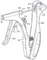
图1为本发明一实施例提供的组织缝合枪处于释放状态结构示意图;1 is a schematic structural diagram of a tissue suture gun in a released state provided by an embodiment of the present invention;
图2为本发明一实施例提供的组织缝合枪处于释放状态剖面结构示意图;2 is a schematic cross-sectional structural diagram of a tissue suture gun in a released state provided by an embodiment of the present invention;
图3为本发明一实施例提供的缝合枪手柄放大结构示意图;3 is a schematic diagram of an enlarged structure of a suture gun handle provided by an embodiment of the present invention;
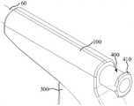
图4为本发明一实施例提供的组织缝合枪局部结构示意图;4 is a schematic diagram of a partial structure of a tissue suture gun provided by an embodiment of the present invention;
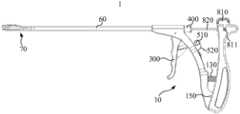
图5为本发明一实施例提供的组织缝合枪处于夹紧状态结构示意图;5 is a schematic structural diagram of a tissue suture gun in a clamped state provided by an embodiment of the present invention;
图6为本发明一实施例提供的组织缝合枪处于释放状态立体结构示意图;6 is a schematic three-dimensional structural diagram of a tissue suture gun in a released state according to an embodiment of the present invention;
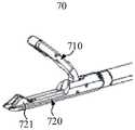
图7为本发明一实施例提供的枪头立体结构示意图;7 is a schematic diagram of a three-dimensional structure of a gun tip provided by an embodiment of the present invention;
图8为本发明一实施例提供的枪头平面结构示意图;8 is a schematic diagram of a plane structure of a gun head provided by an embodiment of the present invention;
图9为本发明一实施例提供的缝合针的针头结构示意图。FIG. 9 is a schematic diagram of a needle head structure of a suture needle according to an embodiment of the present invention.
其中:1、组织缝合枪;10、缝合枪手柄;100、前枪柄;110、安装孔;120、穿入孔;130、第二复位件;140、第一复位件;150、导向槽;200、后枪柄;210、固定槽;220、导向柱;300、扳机;400、穿入连接管;410、翻边;500、锁定结构;510、锁定轴;511、楔形齿;520、弹性锁件;521、楔形钩;60、枪杆;70、枪头;710、上夹板;711、穿出孔;720、下夹板;721、引导部;730、压合板;731、挂齿;740、压合扭簧;80、缝合针;810、针座;811、固定柱;820、针杆;830、针头;831、勾线槽。Wherein: 1. tissue suture gun; 10, suture gun handle; 100, front gun handle; 110, mounting hole; 120, penetration hole; 130, second reset piece; 140, first reset piece; 150, guide groove; 200, rear handle; 210, fixing slot; 220, guide post; 300, trigger; 400, penetrating connecting pipe; 410, flanging; 500, locking structure; 510, locking shaft; 511, wedge tooth; 520, elasticity Lock; 521, wedge hook; 60, gun barrel; 70, gun head; 710, upper splint; 711, punching hole; 720, lower splint; 721, guide part; 730, pressing plate; 731, hanging tooth; 740, pressing Close torsion spring; 80, suture needle; 810, needle seat; 811, fixed column; 820, needle bar; 830, needle; 831, hook thread groove.
具体实施方式Detailed ways
为使本发明的上述目的、特征和优点能够更加明显易懂,下面结合附图对本发明的具体实施方式做详细的说明。在下面的描述中阐述了很多具体细节以便于充分理解本发明。但是本发明能够以很多不同于在此描述的其它方式来实施,本领域技术人员可以在不违背本发明内涵的情况下做类似改进,因此本发明不受下面公开的具体实施例的限制。In order to make the above objects, features and advantages of the present invention more clearly understood, the specific embodiments of the present invention will be described in detail below with reference to the accompanying drawings. In the following description, numerous specific details are set forth in order to provide a thorough understanding of the present invention. However, the present invention can be implemented in many other ways different from those described herein, and those skilled in the art can make similar improvements without departing from the connotation of the present invention. Therefore, the present invention is not limited by the specific embodiments disclosed below.
在本发明的描述中,需要理解的是,术语“中心”、“纵向”、“横向”、“长度”、“宽度”、“厚度”、“上”、“下”、“前”、“后”、“左”、“右”、“竖直”、“水平”、“顶”、“底”、“内”、“外”、“顺时针”、“逆时针”、“轴向”、“径向”、“周向”等指示的方位或位置关系为基于附图所示的方位或位置关系,仅是为了便于描述本发明和简化描述,而不是指示或暗示所指的装置或元件必须具有特定的方位、以特定的方位构造和操作,因此不能理解为对本发明的限制。In the description of the present invention, it should be understood that the terms "center", "longitudinal", "lateral", "length", "width", "thickness", "upper", "lower", "front", " Back, Left, Right, Vertical, Horizontal, Top, Bottom, Inner, Outer, Clockwise, Counterclockwise, Axial , "radial", "circumferential" and other indicated orientations or positional relationships are based on the orientations or positional relationships shown in the accompanying drawings, and are only for the convenience of describing the present invention and simplifying the description, rather than indicating or implying the indicated device or Elements must have a particular orientation, be constructed and operate in a particular orientation and are therefore not to be construed as limitations of the invention.
此外,术语“第一”、“第二”仅用于描述目的,而不能理解为指示或暗示相对重要性或者隐含指明所指示的技术特征的数量。由此,限定有“第一”、“第二”的特征可以明示或者隐含地包括至少一个该特征。在本发明的描述中,“多个”的含义是至少两个,例如两个,三个等,除非另有明确具体的限定。In addition, the terms "first" and "second" are only used for descriptive purposes, and should not be construed as indicating or implying relative importance or implying the number of indicated technical features. Thus, a feature delimited with "first", "second" may expressly or implicitly include at least one of that feature. In the description of the present invention, "plurality" means at least two, such as two, three, etc., unless otherwise expressly and specifically defined.
在本发明中,除非另有明确的规定和限定,术语“安装”、“相连”、“连接”、“固定”等术语应做广义理解,例如,可以是固定连接,也可以是可拆卸连接,或成一体;可以是机械连接,也可以是电连接;可以是直接相连,也可以通过中间媒介间接相连,可以是两个元件内部的连通或两个元件的相互作用关系,除非另有明确的限定。对于本领域的普通技术人员而言,可以根据具体情况理解上述术语在本发明中的具体含义。In the present invention, unless otherwise expressly specified and limited, the terms "installed", "connected", "connected", "fixed" and other terms should be understood in a broad sense, for example, it may be a fixed connection or a detachable connection , or integrated; it can be a mechanical connection or an electrical connection; it can be directly connected or indirectly connected through an intermediate medium, it can be the internal connection of two elements or the interaction relationship between the two elements, unless otherwise specified limit. For those of ordinary skill in the art, the specific meanings of the above terms in the present invention can be understood according to specific situations.
在本发明中,除非另有明确的规定和限定,第一特征在第二特征“上”或“下”可以是第一和第二特征直接接触,或第一和第二特征通过中间媒介间接接触。而且,第一特征在第二特征“之上”、“上方”和“上面”可是第一特征在第二特征正上方或斜上方,或仅仅表示第一特征水平高度高于第二特征。第一特征在第二特征“之下”、“下方”和“下面”可以是第一特征在第二特征正下方或斜下方,或仅仅表示第一特征水平高度小于第二特征。In the present invention, unless otherwise expressly specified and limited, a first feature "on" or "under" a second feature may be in direct contact between the first and second features, or the first and second features indirectly through an intermediary touch. Also, the first feature being "above", "over" and "above" the second feature may mean that the first feature is directly above or obliquely above the second feature, or simply means that the first feature is level higher than the second feature. The first feature being "below", "below" and "below" the second feature may mean that the first feature is directly below or obliquely below the second feature, or simply means that the first feature has a lower level than the second feature.
需要说明的是,当元件被称为“固定于”或“设置于”另一个元件,它可以直接在另一个元件上或者也可以存在居中的元件。当一个元件被认为是“连接”另一个元件,它可以是直接连接到另一个元件或者可能同时存在居中元件。本文所使用的术语“垂直的”、“水平的”、“上”、“下”、“左”、“右”以及类似的表述只是为了说明的目的,并不表示是唯一的实施方式。It should be noted that when an element is referred to as being "fixed to" or "disposed on" another element, it can be directly on the other element or an intervening element may also be present. When an element is referred to as being "connected" to another element, it can be directly connected to the other element or intervening elements may also be present. The terms "vertical", "horizontal", "upper", "lower", "left", "right" and similar expressions used herein are for the purpose of illustration only and do not represent the only embodiment.
缝合枪是半月板等软骨组织的缝合修复过程中需要使用的手术器械,并且缝合枪在术前和/或术后的清洗、消毒是保证缝合修复手术顺利进行的前提。本发明提供一种便于清洗消毒的缝合枪手柄以及使用此种手柄的组织缝合枪。可以理解的,本发明提供的缝合枪手柄以及组织缝合枪不仅能够用于半月板的缝合,还能用于其他软骨组织或者软组织的缝合;为便于说明,以下各个实施例仅以半月板的缝合修复为例进行说明。The suture gun is a surgical instrument that needs to be used in the process of suture repair of cartilage tissue such as meniscus, and the cleaning and disinfection of the suture gun before and/or after the operation is the premise to ensure the smooth progress of the suture repair operation. The present invention provides a suture gun handle which is convenient for cleaning and disinfection, and a tissue suture gun using the handle. It can be understood that the suture gun handle and the tissue suture gun provided by the present invention can not only be used for the suture of the meniscus, but also for the suture of other cartilage tissues or soft tissues; Repair as an example.
如图1-3所示,本发明一实施例提供一种缝合枪手柄10,能够与枪杆60、枪头70以及缝合针80配合使用完成半月板的缝合。缝合枪包括前枪柄100、后枪柄200、扳机300以及穿入接头。前枪柄100上开设安装孔110和穿入孔120,安装孔110用于安装枪杆60,穿入孔120和安装孔110连通,穿入孔120和安装孔110允许缝合针80沿插入方向依次穿入。后枪柄200活动设置于前枪柄100靠近穿入孔120的一侧,后枪柄200活动时能够推动缝合针80沿插入方向移动。扳机300活动设置于前枪柄100,扳机300活动时能够驱动与其传动连接的枪头70动作。穿入接头设置于穿入孔120远离安装孔110的一端,穿入接头允许缝合针80穿入,穿入接头能够连接洗消管路。上述缝合枪手柄10,前枪柄100、后枪柄200以及扳机300能够与枪杆60以及枪头70配合实现待缝合组织的缝合修复,同时穿入接头不仅能够允许缝合针80穿入,还能够连接洗消管路,进而将清洗、消毒用的液体引入穿入孔120、安装孔110以及固定安装在安装孔110内的枪杆60,实现了缝合枪手柄10以及组织缝合枪1的有效清洗或消毒,可在缝合修复手术前和/或手术后分别进行清洗、消毒,进而保证半月板等软骨组织缝合修复过程的顺利进行。As shown in FIGS. 1-3 , an embodiment of the present invention provides a
需要说明的是,上述实施例中的插入方向指的是缝合针80插入缝合枪手柄10中穿入孔120以及安装孔110的方向,也是在执行缝合动作时后枪柄200推动缝合针80移动的方向;并且当安装孔110与穿入孔120同轴设置时,插入方向还是安装孔110以及穿入孔120的延伸方向;对应图1中示例的缝合枪手柄10以及组织缝合枪1,插入方向大致是水平向左的方向。穿入接头的作用是允许缝合针80插入同时能够连接洗消管路。可选的,穿入接头可以是连接带也可以是连接管。作为一种可实现的方式,如图2-4所示,穿入接头包括穿入连接管400,穿入连接管400的一端可拆卸的固定设置于穿入孔120远离安装孔110的一端。穿入连接管400远离穿入孔120的另一端具有翻边410,翻边410沿穿入连接管400的径向向外翻折。穿入连接管400可拆卸的安装在穿入孔120的一端,允许便捷的拆卸和更换,并且可以仅在需要清洗或消毒时将穿入连接管400安装到穿入孔120,也可以一直将穿入连接管400安装在穿入孔120的一端。并且穿入连接管400上的翻边410能够与洗消管路形成过盈配合,不仅起到密封的作用,还能够防止脱落。It should be noted that the insertion direction in the above embodiment refers to the direction in which the suture needle 80 is inserted into the
可选的,穿入连接管400与穿入孔120之间的可拆卸配合可以是卡接、螺纹连接或者利用可拆卸的中间连接件。在本发明一实施例中,如图2-4所示,穿入连接管400以螺纹连接的方式与穿入孔120远离安装孔110的一端可拆卸的固定连接。螺纹连接不仅具有连接稳固、便于拆装的作用,而且螺纹连接自身具有良好的密封作用,能够有效防止穿入连接管400与穿入孔120的内壁之间溢出洗消液体。需要说明的是,在上述各个实施例中对于前枪柄100、后枪柄200、扳机300以及穿入接头的结构形式并不做具体的限制,只要能够实现其各自对应的功能即可。作为一种可实现的方式,如图1-4所示,前枪柄100大致呈曲率较大的圆弧杆状,后枪柄200大致呈曲率较小的圆弧杆状,并且后枪柄200的底端转动安装在前枪柄100的底端,进而后枪柄200转动时,后枪柄200的顶端靠近或者远离前枪柄100的顶端。同时安装孔110和穿入孔120也同轴开设在前枪柄100的顶端,允许后枪柄200驱动伸入穿入孔120和安装孔110的缝合针80沿插入方向移动。进一步,安装孔110、穿入孔120以及穿入连接管400的截面分别呈圆形,扳机300呈圆弧杆状。在其它的实施例中,前枪柄100、后枪柄200、扳机300以及穿入接头还可以是其他可以实现的结构样式。Optionally, the detachable cooperation between the penetrating
在半月板的缝合修复过程中,如图5所示,需要先驱动枪头70夹紧待缝合的半月板,然后通过后枪柄200驱动缝合针80携带缝合线刺入半月板。在本发明一实施例中,如图2-6所示,缝合枪手柄10还包括锁定结构500。扳机300活动时具有夹紧位置和释放位置,扳机300活动至夹紧位置时能够驱动与其传动连接的枪头70夹紧待缝合的组织(比如半月板),扳机300活动至释放位置时驱动或者允许与其传动连接的枪头70松开待缝合的组织。锁定结构500设置于前枪柄100,锁定结构500能够维持扳机300处于夹紧位置,或者锁定结构500能够允许扳机300运动至释放位置。锁定结构500维持扳机300处于夹紧位置,进而能够实现枪头70对半月板的持续夹紧,无需操作者持续的施加夹紧力,节省了操作者的操作难度。操作者使用本实施例提供的缝合枪手柄10时可以更加专心的驱动后枪柄200动作。During suture repair of the meniscus, as shown in FIG. 5 , it is necessary to drive the
作为一种可实现的方式,如图2-5所示,锁定结构500包括锁定轴510和弹性锁件520,锁定轴510的中部转动设置于前枪柄100,锁定轴510的一端能够与活动至夹紧位置的扳机300卡接。弹性锁件520固定设置于前枪柄100,弹性锁件520压紧锁定轴510远离扳机300的另一端,弹性锁件520用于保持锁定轴510与扳机300之间的卡接关系(类似于自锁),锁定轴510远离扳机300的另一端受到扰动时允许扳机300活动至释放位置。锁定轴510配合弹性锁件520的结构形式具有结构简单、稳固锁定的优点。进一步,如图2-4所示,弹性锁件520包括弹性锁片,弹性锁片的一端固定设置于前枪柄100,弹性锁片的另一端压紧锁定轴510远离扳机300的另一端。锁定轴510靠近扳机300的一端具有楔形钩521,扳机300转动设置于前枪柄100,扳机300上具有多个楔形齿511,多个楔形齿511沿扳机300的转动方向分布,扳机300转动至夹紧位置的过程中,楔形钩521能够与任一楔形齿511卡合。本实施例中扳机300和锁定轴510之间形成类似棘爪和棘轮的组合形式,在操作者不断搬动扳机300的过程中,锁定轴510能够将扳机300锁定在任一当前的位置,进而允许操作者根据半月板的厚薄情况调整扳机300的转动位置。在其它的实施例中,弹性锁件520还可以是扭簧形式,锁定轴510对扳机300的释放由操作人员按压锁定轴510的另一端实现。As an achievable way, as shown in FIGS. 2-5 , the locking
在本发明一实施例中,如图2-6所示,后枪柄200转动设置于前枪柄100,后枪柄200能够与缝合针80的针座810沿插入方向固定连接。扳机300与前枪柄100之间设置第一复位件140,第一复位件140在扳机300活动至夹紧位置的过程中受压,第一复位件140用于驱动扳机300活动至释放位置。前枪柄100和后枪柄200之间设置第二复位件130,第二复位件130在后枪柄200向靠近前枪柄100方向推动缝合针80时受压,第二复位件130用于驱动后枪柄200向远离前枪柄100方向拉出缝合针80。第一复位件140和第二复位件130实现了扳机300以及后枪柄200的自动复位,降低了半月板缝合修复过程的复杂程度。作为一种可实现的方式,第一复位件140和第二复位件130可以是弹簧、橡胶或者其他弹性结构。如图3-6所示,缝合针80的针座810上具有固定柱811,后枪柄200的顶端开设顶端开口的固定槽210,固定柱811能够从固定槽210的顶端放入固定柱811中,进而在后枪柄200转动的过程中,缝合针80与后枪柄200的顶部沿插入方向(大致水平方向)保持位置固定。进一步,后枪柄200上开设通孔,在不明显降低后枪柄200结构强度的前提下降低缝合枪手柄10的重量。同时在前枪柄100上开设弧形的导向槽150,在后枪柄200上设置导向柱220,导向柱220插入导向槽150中,进而保持后枪柄200相对于前枪柄100的稳定转动。In an embodiment of the present invention, as shown in FIGS. 2-6 , the rear gun handle 200 is rotatably disposed on the
如图1-6所示,本发明一实施例还提供一种组织缝合枪1,包括枪杆60、枪头70和上述各个实施例中任一项所述的缝合枪手柄10,枪杆60的一端固定设置于安装孔110,枪头70设置于枪杆60远离前枪柄100的一端,枪杆60固定设置于安装孔110时,枪头70与扳机300传动连接。上述组织缝合枪1中,前枪柄100、后枪柄200以及扳机300能够与枪杆60以及枪头70配合实现待缝合组织的缝合修复,同时穿入接头不仅能够允许缝合针80穿入,还能够连接洗消管路,进而将清洗、消毒用的液体引入穿入孔120、安装孔110以及固定安装在安装孔110内的枪杆60,实现了缝合枪手柄10以及组织缝合枪1的有效清洗或消毒,可在缝合修复手术前和/或手术后分别进行清洗、消毒,进而保证半月板等软骨组织缝合修复过程的顺利进行。As shown in FIGS. 1-6 , an embodiment of the present invention further provides a
枪杆60的作用是连接枪头70和缝合枪手柄10,可以理解的,枪杆60呈中空的结构,能够允许缝合针80由缝合枪手柄10穿入并且由枪头70刺入半月板。枪头70的作用是夹紧半月板并且引导缝合针80刺入半月板。作为一种可实现的方式,如图6-8所示,枪头70呈鸭嘴夹形式,枪头70包括上夹板710和下夹板720,下夹板720固定设置于枪杆60远离前枪柄100的一端,上夹板710转动设置于下夹板720,上夹板710与扳机300传动连接,扳机300活动时能够驱动上夹板710转动进而夹紧待缝合的组织。下夹板720上具有引导部721,上夹板710上开设穿出孔711,后枪柄200推动缝合针80沿插入方向移动时,引导部721引导缝合针80的针头830由穿出孔711穿出,缝合针80的针头830由穿出孔711穿出后能够刺入被夹紧的半月板中,同时缝合针80的针头830携带缝合线穿过半月板,为下一步继续缝合或者打结奠定基础。鸭嘴夹形式的枪头70具有结构成熟、便于缝合的优点。The function of the
缝合针80的针头830携带缝合线穿过半月板后,操作者减小对后枪柄200的驱动力,后枪柄200的顶端远离前枪柄100运动,进而缝合针80在后枪柄200的带动下沿插入方向的反向运动,缝合针80的针头830沿刺入的路径缩回枪头70内。在缝合针80的针头830缩回枪头70时,需要避免缝合线随针头830一起缩回枪头70内。在本发明一实施例中,如图6-8所示,枪头70还包括压合板730和压合扭簧740,压合板730转动设置于上夹板710,压合板730转动时遮蔽穿出孔711或者避让穿出孔711,压合扭簧740设置于压合板730和上夹板710之间,压合扭簧740用于驱动压合板730转动至遮蔽穿出孔711的位置。压合板730的外周缘具有挂齿731,压合板730转动至遮蔽穿出孔711的位置时,挂齿731配合上夹板710咬合随针头830伸出穿出孔711的缝合线。在本实施例中,压合板730在压合扭簧740的作用下遮蔽穿出孔711,缝合针80的针头830伸出穿出孔711时能够将压合板730抵接,并且驱动压合板730转动进而允许缝合针80的针头830穿出。当缝合针80的针头830缩回枪头70内时,压合板730上的挂齿731咬紧缝合线,进而保持缝合线穿过半月板,为下一步继续缝合或者打结奠定基础。After the
作为一种可实现的方式,引导部721包括开设于下夹板720上的翘曲滑槽,翘曲滑槽开设于下夹板720靠近上夹板710的一侧,翘曲滑槽由下夹板720指向穿出孔711。上夹板710与扳机300之间通过连接杆传动连接,并且连接杆也可以设置在枪杆60内;具体的,连接杆与扳机300的顶部连接,连接杆用于将扳机300顶部的转动转化为上夹板710的转动。翘曲滑槽能够有效引导缝合针80的针头830改变水平的前进方向进而沿竖直方向由穿出孔711穿出。进一步,翘曲滑槽的内壁是圆滑曲面,比如圆弧面。在其它的实施例中,引导部721还可以是导向管或者导向轮。在本发明一实施例中,组织缝合枪1还包括缝合针80,如图5-6及图9所示,缝合针80能够活动穿设于枪头70、枪杆60以及前枪柄100。作为一种可实现的方式,缝合针80包括针座810、针杆820和针头830,针杆820的一端固定设置于针座810,针头830固定设置于针杆820远离针座810的另一端。针座810能够与后枪柄200沿插入方向固定连接,针杆820和针头830能够活动穿设于枪头70、枪杆60或者前枪柄100。所述针头830能够发生弯曲弹性变形,进而避免针头830穿过翘曲滑槽时被损坏。同时针头830远离针杆820的一端开设勾线槽831,勾线槽831能够携带缝合线穿过半月板。As an achievable way, the
以上所述实施例的各技术特征可以进行任意的组合,为使描述简洁,未对上述实施例中的各个技术特征所有可能的组合都进行描述,然而,只要这些技术特征的组合不存在矛盾,都应当认为是本说明书记载的范围。The technical features of the above-described embodiments can be combined arbitrarily. For the sake of brevity, all possible combinations of the technical features in the above-described embodiments are not described. However, as long as there is no contradiction between the combinations of these technical features, All should be regarded as the scope described in this specification.
以上所述实施例仅表达了本发明的几种实施方式,其描述较为具体和详细,但并不能因此而理解为对发明专利范围的限制。应当指出的是,对于本领域的普通技术人员来说,在不脱离本发明构思的前提下,还可以做出若干变形和改进,这些都属于本发明的保护范围。因此,本发明专利的保护范围应以所附权利要求为准。The above-mentioned embodiments only represent several embodiments of the present invention, and the descriptions thereof are more specific and detailed, but should not be construed as a limitation on the scope of the invention patent. It should be pointed out that for those skilled in the art, without departing from the concept of the present invention, several modifications and improvements can be made, which all belong to the protection scope of the present invention. Therefore, the protection scope of the patent of the present invention should be subject to the appended claims.
Claims (13)
Translated fromChinesePriority Applications (1)
| Application Number | Priority Date | Filing Date | Title |
|---|---|---|---|
| CN202010588848.6ACN111803153A (en) | 2020-06-24 | 2020-06-24 | Suture gun handle and tissue suture gun |
Applications Claiming Priority (1)
| Application Number | Priority Date | Filing Date | Title |
|---|---|---|---|
| CN202010588848.6ACN111803153A (en) | 2020-06-24 | 2020-06-24 | Suture gun handle and tissue suture gun |
Publications (1)
| Publication Number | Publication Date |
|---|---|
| CN111803153Atrue CN111803153A (en) | 2020-10-23 |
Family
ID=72856421
Family Applications (1)
| Application Number | Title | Priority Date | Filing Date |
|---|---|---|---|
| CN202010588848.6APendingCN111803153A (en) | 2020-06-24 | 2020-06-24 | Suture gun handle and tissue suture gun |
Country Status (1)
| Country | Link |
|---|---|
| CN (1) | CN111803153A (en) |
Cited By (4)
| Publication number | Priority date | Publication date | Assignee | Title |
|---|---|---|---|---|
| CN112914638A (en)* | 2021-03-19 | 2021-06-08 | 常州市第一人民医院 | Orthopedics sewing gun convenient to use |
| CN112971881A (en)* | 2021-02-02 | 2021-06-18 | 杭州锐健马斯汀医疗器材有限公司 | Joint mirror lower meniscus anterior angle sewing gun |
| CN116138823A (en)* | 2023-02-24 | 2023-05-23 | 北京大学第三医院(北京大学第三临床医学院) | Stitching device |
| CN119454131A (en)* | 2024-12-04 | 2025-02-18 | 青岛智兴医疗器械有限公司 | A two-stage pressing suture gun |
Citations (8)
| Publication number | Priority date | Publication date | Assignee | Title |
|---|---|---|---|---|
| CA2510080A1 (en)* | 2004-06-17 | 2005-12-17 | Ethicon, Inc. | Minimally invasive stitching device |
| WO2010127274A1 (en)* | 2009-05-01 | 2010-11-04 | Cayenne Medical, Inc. | Meniscal repair systems and methods |
| CN204092062U (en)* | 2014-07-21 | 2015-01-14 | 陈斐 | A kind of serious symptom medical science gun-type operation needle |
| CN106535780A (en)* | 2014-06-06 | 2017-03-22 | 伊西康内外科有限责任公司 | Circular needle driver |
| CN208464160U (en)* | 2017-11-21 | 2019-02-05 | 丁伟 | A kind of meniscus root stitching unstrument |
| CN110123400A (en)* | 2019-05-22 | 2019-08-16 | 杭州锐健马斯汀医疗器材有限公司 | A kind of device for meniscus suture |
| CN209899517U (en)* | 2019-03-06 | 2020-01-07 | 杭州锐健马斯汀医疗器材有限公司 | Instrument for rotator cuff repair surgery |
| CN212438722U (en)* | 2020-06-24 | 2021-02-02 | 北京德益达美医疗科技有限公司 | Suture gun handle and tissue suture gun |
- 2020
- 2020-06-24CNCN202010588848.6Apatent/CN111803153A/enactivePending
Patent Citations (8)
| Publication number | Priority date | Publication date | Assignee | Title |
|---|---|---|---|---|
| CA2510080A1 (en)* | 2004-06-17 | 2005-12-17 | Ethicon, Inc. | Minimally invasive stitching device |
| WO2010127274A1 (en)* | 2009-05-01 | 2010-11-04 | Cayenne Medical, Inc. | Meniscal repair systems and methods |
| CN106535780A (en)* | 2014-06-06 | 2017-03-22 | 伊西康内外科有限责任公司 | Circular needle driver |
| CN204092062U (en)* | 2014-07-21 | 2015-01-14 | 陈斐 | A kind of serious symptom medical science gun-type operation needle |
| CN208464160U (en)* | 2017-11-21 | 2019-02-05 | 丁伟 | A kind of meniscus root stitching unstrument |
| CN209899517U (en)* | 2019-03-06 | 2020-01-07 | 杭州锐健马斯汀医疗器材有限公司 | Instrument for rotator cuff repair surgery |
| CN110123400A (en)* | 2019-05-22 | 2019-08-16 | 杭州锐健马斯汀医疗器材有限公司 | A kind of device for meniscus suture |
| CN212438722U (en)* | 2020-06-24 | 2021-02-02 | 北京德益达美医疗科技有限公司 | Suture gun handle and tissue suture gun |
Cited By (6)
| Publication number | Priority date | Publication date | Assignee | Title |
|---|---|---|---|---|
| CN112971881A (en)* | 2021-02-02 | 2021-06-18 | 杭州锐健马斯汀医疗器材有限公司 | Joint mirror lower meniscus anterior angle sewing gun |
| CN112914638A (en)* | 2021-03-19 | 2021-06-08 | 常州市第一人民医院 | Orthopedics sewing gun convenient to use |
| CN112914638B (en)* | 2021-03-19 | 2022-02-11 | 常州市第一人民医院 | Orthopedics sewing gun convenient to use |
| CN116138823A (en)* | 2023-02-24 | 2023-05-23 | 北京大学第三医院(北京大学第三临床医学院) | Stitching device |
| CN119454131A (en)* | 2024-12-04 | 2025-02-18 | 青岛智兴医疗器械有限公司 | A two-stage pressing suture gun |
| CN119454131B (en)* | 2024-12-04 | 2025-08-01 | 青岛智兴医疗器械有限公司 | Secondary pressing type stitching gun |
Similar Documents
| Publication | Publication Date | Title |
|---|---|---|
| CN111803153A (en) | Suture gun handle and tissue suture gun | |
| JP3880907B2 (en) | Endoscopic suture device | |
| US5431666A (en) | Surgical suture instrument | |
| JP3782135B2 (en) | Loading unit used for surgical suturing device | |
| JP4154500B2 (en) | Surgical needle | |
| US9610075B2 (en) | Suture passing devices and methods | |
| US8663251B2 (en) | In-line suture passer and method of passing suture | |
| JP5367564B2 (en) | Tendon repair assembly, tendon engagement member and bone penetration assembly | |
| KR20190100159A (en) | Endoscopic Suture System with External Tool Channel | |
| EP2314238B1 (en) | Fixation device for suturing and restoring a temporomandibular joint disc | |
| US20100249807A1 (en) | Surgical purse-string suturing instrument | |
| CN212346609U (en) | Suturing device, treatment device with suturing device and treatment system | |
| US20230165581A1 (en) | Suture device, treatment device with suture device, and treatment system | |
| US9867609B2 (en) | Laparoscopic suture device with stripper plate | |
| CN115996682A (en) | Endoscopic stitching device | |
| US20250302467A1 (en) | Suturing devices, and therapeutic apparatuses and therapeutic devices with suturing devices | |
| CN115944335A (en) | Stapler, therapeutic device with stapler and therapeutic equipment | |
| WO2025055526A1 (en) | Suturing device | |
| CN212438722U (en) | Suture gun handle and tissue suture gun | |
| CN102056550B (en) | Remote control device for needles used in non-invasive surgery | |
| CN219661796U (en) | Suturing devices, treatment devices and treatment equipment having suturing devices | |
| CN118717287A (en) | Surgical system and its anchor delivery system, magazine and robotic arm | |
| CN115462850A (en) | Suture Needle Holder Assembly for Disposable Laparoscopic Stapler | |
| CN212490018U (en) | Suture line implanting device and suture line | |
| CN219814206U (en) | Digestive endoscope suturing device |
Legal Events
| Date | Code | Title | Description |
|---|---|---|---|
| PB01 | Publication | ||
| PB01 | Publication | ||
| SE01 | Entry into force of request for substantive examination | ||
| SE01 | Entry into force of request for substantive examination |