CN111801711A - Image annotation - Google Patents
Image annotationDownload PDFInfo
- Publication number
- CN111801711A CN111801711ACN201980016667.1ACN201980016667ACN111801711ACN 111801711 ACN111801711 ACN 111801711ACN 201980016667 ACN201980016667 ACN 201980016667ACN 111801711 ACN111801711 ACN 111801711A
- Authority
- CN
- China
- Prior art keywords
- image
- vehicle
- road
- capture device
- image capture
- Prior art date
- Legal status (The legal status is an assumption and is not a legal conclusion. Google has not performed a legal analysis and makes no representation as to the accuracy of the status listed.)
- Granted
Links
Images


Classifications
- G—PHYSICS
- G06—COMPUTING OR CALCULATING; COUNTING
- G06T—IMAGE DATA PROCESSING OR GENERATION, IN GENERAL
- G06T7/00—Image analysis
- G06T7/70—Determining position or orientation of objects or cameras
- G06T7/73—Determining position or orientation of objects or cameras using feature-based methods
- G06T7/75—Determining position or orientation of objects or cameras using feature-based methods involving models
- G—PHYSICS
- G06—COMPUTING OR CALCULATING; COUNTING
- G06T—IMAGE DATA PROCESSING OR GENERATION, IN GENERAL
- G06T7/00—Image analysis
- G06T7/50—Depth or shape recovery
- G06T7/55—Depth or shape recovery from multiple images
- G06T7/579—Depth or shape recovery from multiple images from motion
- G—PHYSICS
- G01—MEASURING; TESTING
- G01C—MEASURING DISTANCES, LEVELS OR BEARINGS; SURVEYING; NAVIGATION; GYROSCOPIC INSTRUMENTS; PHOTOGRAMMETRY OR VIDEOGRAMMETRY
- G01C21/00—Navigation; Navigational instruments not provided for in groups G01C1/00 - G01C19/00
- G01C21/26—Navigation; Navigational instruments not provided for in groups G01C1/00 - G01C19/00 specially adapted for navigation in a road network
- G01C21/28—Navigation; Navigational instruments not provided for in groups G01C1/00 - G01C19/00 specially adapted for navigation in a road network with correlation of data from several navigational instruments
- G01C21/30—Map- or contour-matching
- B—PERFORMING OPERATIONS; TRANSPORTING
- B60—VEHICLES IN GENERAL
- B60W—CONJOINT CONTROL OF VEHICLE SUB-UNITS OF DIFFERENT TYPE OR DIFFERENT FUNCTION; CONTROL SYSTEMS SPECIALLY ADAPTED FOR HYBRID VEHICLES; ROAD VEHICLE DRIVE CONTROL SYSTEMS FOR PURPOSES NOT RELATED TO THE CONTROL OF A PARTICULAR SUB-UNIT
- B60W60/00—Drive control systems specially adapted for autonomous road vehicles
- B60W60/001—Planning or execution of driving tasks
- G—PHYSICS
- G01—MEASURING; TESTING
- G01C—MEASURING DISTANCES, LEVELS OR BEARINGS; SURVEYING; NAVIGATION; GYROSCOPIC INSTRUMENTS; PHOTOGRAMMETRY OR VIDEOGRAMMETRY
- G01C21/00—Navigation; Navigational instruments not provided for in groups G01C1/00 - G01C19/00
- G01C21/26—Navigation; Navigational instruments not provided for in groups G01C1/00 - G01C19/00 specially adapted for navigation in a road network
- G01C21/34—Route searching; Route guidance
- G01C21/36—Input/output arrangements for on-board computers
- G01C21/3602—Input other than that of destination using image analysis, e.g. detection of road signs, lanes, buildings, real preceding vehicles using a camera
- G—PHYSICS
- G01—MEASURING; TESTING
- G01C—MEASURING DISTANCES, LEVELS OR BEARINGS; SURVEYING; NAVIGATION; GYROSCOPIC INSTRUMENTS; PHOTOGRAMMETRY OR VIDEOGRAMMETRY
- G01C21/00—Navigation; Navigational instruments not provided for in groups G01C1/00 - G01C19/00
- G01C21/38—Electronic maps specially adapted for navigation; Updating thereof
- G01C21/3804—Creation or updating of map data
- G01C21/3807—Creation or updating of map data characterised by the type of data
- G01C21/3815—Road data
- G01C21/3819—Road shape data, e.g. outline of a route
- G—PHYSICS
- G01—MEASURING; TESTING
- G01C—MEASURING DISTANCES, LEVELS OR BEARINGS; SURVEYING; NAVIGATION; GYROSCOPIC INSTRUMENTS; PHOTOGRAMMETRY OR VIDEOGRAMMETRY
- G01C21/00—Navigation; Navigational instruments not provided for in groups G01C1/00 - G01C19/00
- G01C21/38—Electronic maps specially adapted for navigation; Updating thereof
- G01C21/3804—Creation or updating of map data
- G01C21/3807—Creation or updating of map data characterised by the type of data
- G01C21/3815—Road data
- G01C21/3822—Road feature data, e.g. slope data
- G—PHYSICS
- G06—COMPUTING OR CALCULATING; COUNTING
- G06F—ELECTRIC DIGITAL DATA PROCESSING
- G06F18/00—Pattern recognition
- G06F18/20—Analysing
- G06F18/21—Design or setup of recognition systems or techniques; Extraction of features in feature space; Blind source separation
- G06F18/214—Generating training patterns; Bootstrap methods, e.g. bagging or boosting
- G—PHYSICS
- G06—COMPUTING OR CALCULATING; COUNTING
- G06T—IMAGE DATA PROCESSING OR GENERATION, IN GENERAL
- G06T7/00—Image analysis
- G06T7/30—Determination of transform parameters for the alignment of images, i.e. image registration
- G06T7/33—Determination of transform parameters for the alignment of images, i.e. image registration using feature-based methods
- G06T7/344—Determination of transform parameters for the alignment of images, i.e. image registration using feature-based methods involving models
- G—PHYSICS
- G06—COMPUTING OR CALCULATING; COUNTING
- G06T—IMAGE DATA PROCESSING OR GENERATION, IN GENERAL
- G06T7/00—Image analysis
- G06T7/50—Depth or shape recovery
- G—PHYSICS
- G06—COMPUTING OR CALCULATING; COUNTING
- G06V—IMAGE OR VIDEO RECOGNITION OR UNDERSTANDING
- G06V10/00—Arrangements for image or video recognition or understanding
- G06V10/70—Arrangements for image or video recognition or understanding using pattern recognition or machine learning
- G06V10/82—Arrangements for image or video recognition or understanding using pattern recognition or machine learning using neural networks
- G—PHYSICS
- G06—COMPUTING OR CALCULATING; COUNTING
- G06V—IMAGE OR VIDEO RECOGNITION OR UNDERSTANDING
- G06V10/00—Arrangements for image or video recognition or understanding
- G06V10/94—Hardware or software architectures specially adapted for image or video understanding
- G06V10/945—User interactive design; Environments; Toolboxes
- G—PHYSICS
- G06—COMPUTING OR CALCULATING; COUNTING
- G06V—IMAGE OR VIDEO RECOGNITION OR UNDERSTANDING
- G06V20/00—Scenes; Scene-specific elements
- G06V20/50—Context or environment of the image
- G06V20/56—Context or environment of the image exterior to a vehicle by using sensors mounted on the vehicle
- G06V20/588—Recognition of the road, e.g. of lane markings; Recognition of the vehicle driving pattern in relation to the road
- B—PERFORMING OPERATIONS; TRANSPORTING
- B60—VEHICLES IN GENERAL
- B60W—CONJOINT CONTROL OF VEHICLE SUB-UNITS OF DIFFERENT TYPE OR DIFFERENT FUNCTION; CONTROL SYSTEMS SPECIALLY ADAPTED FOR HYBRID VEHICLES; ROAD VEHICLE DRIVE CONTROL SYSTEMS FOR PURPOSES NOT RELATED TO THE CONTROL OF A PARTICULAR SUB-UNIT
- B60W2420/00—Indexing codes relating to the type of sensors based on the principle of their operation
- B60W2420/40—Photo, light or radio wave sensitive means, e.g. infrared sensors
- B60W2420/403—Image sensing, e.g. optical camera
- B—PERFORMING OPERATIONS; TRANSPORTING
- B60—VEHICLES IN GENERAL
- B60W—CONJOINT CONTROL OF VEHICLE SUB-UNITS OF DIFFERENT TYPE OR DIFFERENT FUNCTION; CONTROL SYSTEMS SPECIALLY ADAPTED FOR HYBRID VEHICLES; ROAD VEHICLE DRIVE CONTROL SYSTEMS FOR PURPOSES NOT RELATED TO THE CONTROL OF A PARTICULAR SUB-UNIT
- B60W2552/00—Input parameters relating to infrastructure
- B60W2552/20—Road profile, i.e. the change in elevation or curvature of a plurality of continuous road segments
- G—PHYSICS
- G06—COMPUTING OR CALCULATING; COUNTING
- G06T—IMAGE DATA PROCESSING OR GENERATION, IN GENERAL
- G06T2207/00—Indexing scheme for image analysis or image enhancement
- G06T2207/10—Image acquisition modality
- G06T2207/10004—Still image; Photographic image
- G—PHYSICS
- G06—COMPUTING OR CALCULATING; COUNTING
- G06T—IMAGE DATA PROCESSING OR GENERATION, IN GENERAL
- G06T2207/00—Indexing scheme for image analysis or image enhancement
- G06T2207/10—Image acquisition modality
- G06T2207/10016—Video; Image sequence
- G—PHYSICS
- G06—COMPUTING OR CALCULATING; COUNTING
- G06T—IMAGE DATA PROCESSING OR GENERATION, IN GENERAL
- G06T2207/00—Indexing scheme for image analysis or image enhancement
- G06T2207/10—Image acquisition modality
- G06T2207/10028—Range image; Depth image; 3D point clouds
- G—PHYSICS
- G06—COMPUTING OR CALCULATING; COUNTING
- G06T—IMAGE DATA PROCESSING OR GENERATION, IN GENERAL
- G06T2207/00—Indexing scheme for image analysis or image enhancement
- G06T2207/20—Special algorithmic details
- G06T2207/20076—Probabilistic image processing
- G—PHYSICS
- G06—COMPUTING OR CALCULATING; COUNTING
- G06T—IMAGE DATA PROCESSING OR GENERATION, IN GENERAL
- G06T2207/00—Indexing scheme for image analysis or image enhancement
- G06T2207/20—Special algorithmic details
- G06T2207/20084—Artificial neural networks [ANN]
- G—PHYSICS
- G06—COMPUTING OR CALCULATING; COUNTING
- G06T—IMAGE DATA PROCESSING OR GENERATION, IN GENERAL
- G06T2207/00—Indexing scheme for image analysis or image enhancement
- G06T2207/20—Special algorithmic details
- G06T2207/20212—Image combination
- G06T2207/20221—Image fusion; Image merging
- G—PHYSICS
- G06—COMPUTING OR CALCULATING; COUNTING
- G06T—IMAGE DATA PROCESSING OR GENERATION, IN GENERAL
- G06T2207/00—Indexing scheme for image analysis or image enhancement
- G06T2207/30—Subject of image; Context of image processing
- G06T2207/30244—Camera pose
- G—PHYSICS
- G06—COMPUTING OR CALCULATING; COUNTING
- G06T—IMAGE DATA PROCESSING OR GENERATION, IN GENERAL
- G06T2207/00—Indexing scheme for image analysis or image enhancement
- G06T2207/30—Subject of image; Context of image processing
- G06T2207/30248—Vehicle exterior or interior
- G06T2207/30252—Vehicle exterior; Vicinity of vehicle
- G06T2207/30256—Lane; Road marking
Landscapes
- Engineering & Computer Science (AREA)
- Physics & Mathematics (AREA)
- General Physics & Mathematics (AREA)
- Theoretical Computer Science (AREA)
- Radar, Positioning & Navigation (AREA)
- Remote Sensing (AREA)
- Computer Vision & Pattern Recognition (AREA)
- Multimedia (AREA)
- Automation & Control Theory (AREA)
- Evolutionary Computation (AREA)
- Software Systems (AREA)
- Artificial Intelligence (AREA)
- Data Mining & Analysis (AREA)
- Computing Systems (AREA)
- Databases & Information Systems (AREA)
- General Health & Medical Sciences (AREA)
- Medical Informatics (AREA)
- Health & Medical Sciences (AREA)
- Mechanical Engineering (AREA)
- Human Computer Interaction (AREA)
- Transportation (AREA)
- Bioinformatics & Cheminformatics (AREA)
- Bioinformatics & Computational Biology (AREA)
- Evolutionary Biology (AREA)
- General Engineering & Computer Science (AREA)
- Life Sciences & Earth Sciences (AREA)
- Image Analysis (AREA)
- Image Processing (AREA)
- Traffic Control Systems (AREA)
- Navigation (AREA)
Abstract
Translated fromChinese
Description
Translated fromChinese技术领域technical field
本公开涉及图像标注,诸如带标注的街道道路图像的创建,该街道道路图像可以(尤其)用于训练机器学习道路检测部件。本公开还涉及可以在这个背景下使用的相关系统和方法,但是该相关系统和方法也具有在其他背景下的应用。The present disclosure relates to image annotation, such as the creation of annotated street road images that can be used, among other things, to train machine learning road detection components. The present disclosure also relates to related systems and methods that can be used in this context, but the related systems and methods have applications in other contexts as well.
背景技术Background technique
快速新兴的技术是自主车辆(AV),自主车辆可以在城市道路和其他道路上自行导航。这种车辆不仅必须在人和其它车辆之间执行复杂的操控,而且它们必须经常这么做直到确保对不利事件发生的概率的严格约束,不利事件例如为与环境中的这些其它智能体的碰撞。为了使AV安全地计划,能够准确且可靠地观察其环境是至关重要的。这包括对车辆附近的道路结构的准确的和可靠的检测的需要。A rapidly emerging technology is autonomous vehicles (AVs) that can navigate urban roads and other roads by themselves. Such vehicles must not only perform complex maneuvers between humans and other vehicles, but they must often do so until tight constraints on the probability of adverse events, such as collisions with these other agents in the environment, are ensured. In order for an AV to plan safely, it is critical to be able to observe its environment accurately and reliably. This includes the need for accurate and reliable detection of road structures in the vicinity of the vehicle.
因此,在自主驾驶的领域中,常见的要求是具有结构检测部件(也称为机器视觉部件),其在被给予视觉输入时能够确定诸如道路或车道结构的真实世界结构,例如,图像的哪个部分是路面,图像的哪个部分构成道路上的车道等。Thus, in the field of autonomous driving, a common requirement is to have a structure detection component (also known as a machine vision component) that, when given visual input, is able to determine real-world structures such as road or lane structure, for example, which of the image The part is the road surface, which part of the image constitutes a lane on the road, etc.
这经常通过使用卷积神经网络的机器学习来实现。这样的网络需要大量的训练图像。这些训练图像类似于将从自主车辆中的相机看到的图像,但是它们已经被标注有神经网络需要学习的信息。例如,它们将具有标记图像上的哪些像素是路面和/或图像的哪些像素属于车道的标注。在训练时,给网络提供数千或优选地数十万的这种带标注的图像,并且网络自行学习图像的什么特征指示像素是车道的一部分或路面。运行时,网络然后可以利用它之前从未见过的图像,即它在训练期间没有遇到过的图像,自己做出这个决定。This is often achieved through machine learning using convolutional neural networks. Such a network requires a large number of training images. These training images are similar to what you'll see from a camera in an autonomous vehicle, but they've been labeled with information that the neural network needs to learn. For example, they will have annotations marking which pixels on the image are road surfaces and/or which pixels of the image belong to lanes. At training time, the network is provided with thousands or preferably hundreds of thousands of such annotated images, and the network learns by itself what features of the images indicate that a pixel is part of a lane or road surface. At runtime, the network can then make this decision on its own using images it has never seen before, i.e. images it has not encountered during training.
用于创建带标注的训练图像的常规技术是让人类手动标注图像。每幅图像可能花费数十分钟(并且因此招致非常显著的时间、显著的成本以获得所需的大量图像)。使用这种手动过程创建数十万训练图像需要大量的人力,这又使得手动过程成为昂贵的练习。实际上,手动过程对可以实际提供的训练图像的数量施加了限制,这进而可能对训练后的结构检测部件的性能不利。A conventional technique for creating annotated training images is to have humans manually annotate the images. Each image can take tens of minutes (and thus incur very significant time, significant cost to obtain the large number of images required). Creating hundreds of thousands of training images using this manual process requires a lot of manpower, which in turn makes the manual process an expensive exercise. In fact, the manual process imposes a limit on the number of training images that can actually be provided, which in turn may be detrimental to the performance of the trained structure detection part.
自主车辆,也称为自动驾驶车辆,是指具有用于监测其外部环境的传感器系统和能够使用那些传感器自动地做出和实现驾驶决策的控制系统的车辆。这特别包括基于来自传感器系统的输入来自动地适配车辆的速度和行驶方向的能力。完全自主或“无人驾驶”的车辆具有足够的决策能力以在没有来自人类驾驶员的任何输入的情况下操作。然而,如本文所使用的术语自主车辆还适用于半自主车辆,半自主车辆具有更有限的自主决策能力,并且因此仍然需要来自人类驾驶员的一定程度的监督。An autonomous vehicle, also known as an autonomous vehicle, refers to a vehicle that has a sensor system for monitoring its external environment and a control system capable of automatically making and implementing driving decisions using those sensors. This includes in particular the ability to automatically adapt the speed and direction of travel of the vehicle based on input from the sensor system. Fully autonomous or "unmanned" vehicles have sufficient decision-making capabilities to operate without any input from a human driver. However, the term autonomous vehicle as used herein also applies to semi-autonomous vehicles, which have more limited autonomous decision-making capabilities and thus still require some degree of supervision from a human driver.
发明内容SUMMARY OF THE INVENTION
本文解决的核心问题是快速且高效地但是仍然准确地对道路图像进行标注,其中标注指示了视觉道路结构。这样的图像例如可以用于准备非常大的带标注的道路图像的训练集,该训练集适于训练卷积神经网络(CNN)或其他现有技术的机器学习(ML)结构检测部件。The core problem addressed in this paper is to quickly and efficiently but still accurately annotate road images, where the annotations indicate the visual road structure. Such images can be used, for example, to prepare a very large training set of annotated road images suitable for training a convolutional neural network (CNN) or other state-of-the-art machine learning (ML) structure detection components.
通过使用新颖的自动或半自动图像标注技术来解决该问题,下面阐述该技术的各方面和实施例。该技术通过去除或至少显著地减少对人力的需要,允许比这样的手动标注更高效和更快速地生成大量训练图像。This problem is addressed by using novel automatic or semi-automatic image annotation techniques, various aspects and embodiments of which are set forth below. This technique allows large numbers of training images to be generated more efficiently and faster than such manual annotations by removing or at least significantly reducing the need for human labor.
这种训练后的结构检测部件的性能对训练集的质量和大小都有很强的依赖性。生成准确地带标注的道路图像的大训练集的能力(该大训练集的大小简直可能是使用常规标注不实际的)进而意味着有可能当(在运行时)应用于其在训练中未遇到过的图像时增加训练后的结构检测部件的准确性。The performance of such a trained structure detection part is strongly dependent on both the quality and size of the training set. The ability to generate a large training set of accurately labeled road images (the size of this large training set simply might not be practical using regular annotations) in turn means that it is possible that when applied (at runtime) it is not encountered during training increases the accuracy of the trained structure detection component when passing images.
本发明的第一方面提供了一种标注道路图像的方法,该方法包括在图像处理系统处实现以下步骤:接收由行驶车辆的图像捕获装置所捕获的二维图像的时间序列;处理图像以在三维空间中重建车辆所行驶的路径;使用重建后的车辆路径来确定沿着该重建后的车辆路径延伸的预期道路结构;以及通过执行三维空间中的预期道路结构到该图像的二维平面上的几何投影,来生成道路标注数据,以用于采用预期道路结构位置来标记图像中的至少一个。A first aspect of the present invention provides a method of labeling a road image, the method comprising implementing at an image processing system the steps of: receiving a time series of two-dimensional images captured by an image capture device of a moving vehicle; processing the images to reconstructing the path traveled by the vehicle in three-dimensional space; using the reconstructed vehicle path to determine an expected road structure extending along the reconstructed vehicle path; and by applying the expected road structure in three-dimensional space onto the two-dimensional plane of the image to generate road labeling data for labeling at least one of the images with expected road structure locations.
优选地,仅使用从由图像捕获装置所捕获的图像数据导出的信息(即,从所捕获的图像的图像数据导出的车辆路径,以及可选地从由图像捕获装置所捕获的图像数据导出的一个或更多个参考参数)来确定预期道路结构,而不使用任何其他车辆传感器并且不需要图像捕获装置的任何校准。例如,图像捕获装置(图像捕获装置)的一个或更多个参数和/或预期道路结构的一个或更多个参数可以(仅)从图像捕获装置所捕获的图像数据导出。可以使用下面阐述的一种或更多种技术从图像数据中导出。这提供了一种低成本的解决方案,其中采集图像所需的唯一设备是标准车辆和基础相机,例如行车记录仪。Preferably, only information derived from image data captured by the image capture device (ie, the vehicle path derived from the image data of the captured image, and optionally derived from the image data captured by the image capture device) is used. one or more reference parameters) to determine the expected road structure without using any other vehicle sensors and without any calibration of the image capture device. For example, one or more parameters of the image capture device (image capture device) and/or one or more parameters of the expected road structure may be derived (only) from image data captured by the image capture device. It can be derived from the image data using one or more of the techniques set forth below. This provides a low-cost solution where the only equipment required to acquire images is a standard vehicle and a base camera, such as a dash cam.
在实施例中,使用重建后的车辆路径来确定预期道路结构的步骤包括:确定预期道路结构边界,其被定义为平行于重建后的车辆路径延伸的三维空间中的曲线,其中道路标注数据用于标记图像中的预期道路结构边界的位置。In an embodiment, the step of using the reconstructed vehicle path to determine the expected road structure comprises: determining the expected road structure boundary, which is defined as a curve in three-dimensional space extending parallel to the reconstructed vehicle path, wherein the road annotation data is represented by to mark the location of the expected road structure boundary in the image.
在该图像中的预期道路结构位置可以根据在该图像被捕获之后车辆所行驶的路径确定。The expected road structure location in the image can be determined from the path the vehicle traveled after the image was captured.
在该图像中的预期道路结构位置可以根据在该图像被捕获之前车辆所行驶的路径确定。The expected road structure location in the image can be determined from the path the vehicle traveled before the image was captured.
带标注的道路图像可以用于训练针对自主车辆的自动道路检测部件。Annotated road images can be used to train automatic road detection components for autonomous vehicles.
可以基于以下中的至少一个来确定预期道路结构:道路宽度或车道宽度,以及车辆与道路边界或车道边界的偏移。The expected road structure may be determined based on at least one of: road width or lane width, and vehicle offset from the road boundary or lane boundary.
可以对图像的时间序列的至少一部分应用恒定的道路或车道宽度或偏移。A constant road or lane width or offset may be applied to at least a portion of the time series of images.
道路宽度或车道宽度可基于一个或更多个手动宽度调节输入来确定。这些可以根据如下所述的本公开的第四方面来接收。The road width or lane width may be determined based on one or more manual width adjustment inputs. These may be received according to the fourth aspect of the present disclosure as described below.
手动宽度调节输入可以关于一个图像被接收,并且被用于修改预期道路结构并且将修改后的道路结构投影到图像中的一个或更多个其他图像中。Manual width adjustment input may be received with respect to one image and used to modify the expected road structure and project the modified road structure into one or more other of the images.
可以基于道路法向矢量来确定预期道路结构。The expected road structure may be determined based on the road normal vector.
从图像估计的道路法向矢量n为:The road normal vector n estimated from the image is:


可以基于前向方向矢量来确定预期道路结构。The expected road structure may be determined based on the forward direction vector.
从图像估计的前向方向矢量为:The forward direction vector estimated from the image is:


f和n可以用于确定预期道路结构的边界点。f and n can be used to determine the boundary points of the expected road structure.
边界点可以被确定为:Boundary points can be determined as:


Ri是在重建车辆路径时为图像i确定的照相机姿态,gi是图像捕获装置下方的道路点。Ri is the camera pose determined for imagei when reconstructing the vehicle path, andgi is the road point below the image capture device.
摄相机下方的道路点可以被计算为The waypoint below the camera can be calculated as
gi=ci+hRingi=ci +hR in
其中h是照相机的高度,ci是在重建车辆路径时确定的图像捕获装置的3D位置。where h is the height of the camera andci is the 3D position of the image capture device determined when reconstructing the vehicle path.
可以使用同步定位与建图(SLAM)过程来重建车辆路径。The vehicle path can be reconstructed using a Simultaneous Localization and Mapping (SLAM) process.
在执行SLAM过程时,可为每个图像i确定照相机姿态Ri。When performing the SLAM process, the camera pose Ri can be determined for each imagei .
在执行SLAM过程时,可为每个图像i确定3D照相机位置ci。When performing the SLAM process, a 3D camera position ci can be determined for each imagei .
可以基于图像捕获装置的相对角度定向来确定预期道路结构,所述相对角度定向是从根据下面阐述的第四方面或其任何实施例的图像所测量的。The expected road structure may be determined based on the relative angular orientation of the image capture device, measured from images according to the fourth aspect set forth below or any embodiments thereof.
可以基于根据下面阐述的第三方面或其任何实施例的图像所测量的图像捕获装置的相对旋转定向来确定预期道路结构。The expected road structure may be determined based on the relative rotational orientation of the image capture device measured from images according to the third aspect set forth below or any embodiments thereof.
可以基于车辆中的图像捕获装置的高度来执行投影。Projection may be performed based on the height of the image capture device in the vehicle.
可以基于图像捕获装置的重建后的路径的平均高度及从图像计算出的3D道路结构网格来估计高度。The height may be estimated based on the average height of the reconstructed path of the image capture device and a 3D road structure grid calculated from the image.
此外,还认识到,除了上面提出的核心问题之外,上面提出的基于图像的测量技术还可以用于其它情况。因此,这些构成了本公开的可以独立地应用和实现的单独方面。Furthermore, it is also recognized that the image-based measurement techniques proposed above can be used in other situations in addition to the core issues raised above. Accordingly, these constitute separate aspects of the present disclosure that can be independently applied and implemented.
本发明的第二方面提供了一种测量车辆内的图像捕获装置的相对角度定向的方法,该方法包括在图像处理系统处实现以下步骤:接收由车辆的图像捕获装置所捕获的二维图像的时间序列;处理图像以在三维空间中重建车辆所行驶的路径,并且针对重建后的路径上的至少一个参考点来估计图像捕获装置的绝对角度定向;确定前向方向矢量,所述前向方向矢量被定义为重建后的路径上的参考点之前的点与重建后的路径上的参考点之后的点之间的矢量间隔;使用前向方向矢量和针对参考点确定的图像捕获装置的绝对角度定向来确定图像捕获装置相对于车辆的估计角度定向。A second aspect of the present invention provides a method of measuring the relative angular orientation of an image capture device within a vehicle, the method comprising implementing at an image processing system the step of receiving a two-dimensional image of a two-dimensional image captured by the image capture device of the vehicle time series; processing images to reconstruct the path traveled by the vehicle in three-dimensional space, and estimating an absolute angular orientation of the image capture device for at least one reference point on the reconstructed path; determining a forward direction vector, the forward direction A vector is defined as the vector spacing between a point on the reconstructed path before the reference point and a point on the reconstructed path after the reference point; using the forward direction vector and the absolute angle of the image capture device determined for the reference point Orientation to determine an estimated angular orientation of the image capture device relative to the vehicle.
在实施例中,在处理步骤中,可以针对重建后的路径上的多个参考点确定图像捕获装置的绝对角度定向,并且针对每个参考点执行确定和使用步骤,以针对每个参考点确定图像捕获装置相对于车辆的估计角度定向,并且其中,该方法还包括确定相对图像捕获装置角度定向的平均值的步骤。In an embodiment, in the processing step, the absolute angular orientation of the image capture device may be determined for a plurality of reference points on the reconstructed path, and the determining and using steps are performed for each reference point to determine for each reference point The estimated angular orientation of the image capture device relative to the vehicle, and wherein the method further comprises the step of determining an average value of the angular orientation relative to the image capture device.
平均值可以是加权平均值。The average can be a weighted average.
可以根据在较早参考点与较后的参考点之间的路径中呈现的方向变化来对每个相对图像捕获装置角度定向进行加权。Each relative image capture device angular orientation may be weighted according to the change in direction present in the path between the earlier reference point and the later reference point.
该方法还可以包括以下步骤:确定参考点与重建后的路径上的参考点之前的点之间的第一分离矢量;以及确定参考点与重建后的路径上的参考点之后的点之间的第二分离矢量;其中,根据第一分离矢量和第二分离矢量的矢量点积对相对图像捕获装置角度定向中的每一个进行加权。The method may further comprise the steps of: determining a first separation vector between the reference point and a point on the reconstructed path before the reference point; and determining a distance between the reference point and a point on the reconstructed path after the reference point a second separation vector; wherein each of the relative image capture device angular orientations are weighted according to a vector dot product of the first separation vector and the second separation vector.
图像捕获装置相对于车辆的估计角度定向可以是以图像捕获装置的参考系中的车辆的估计纵轴的形式。The estimated angular orientation of the image capture device relative to the vehicle may be in the form of an estimated longitudinal axis of the vehicle in the frame of reference of the image capture device.
参考点或每个参考点可以与该参考点之前的点和该参考点之后的点是等距的。The or each reference point may be equidistant from the point preceding the reference point and the point following the reference point.
图像捕获装置相对于车辆的估计角度定向可以与在路径上的另一点处的图像捕获装置的角度定向的估计一起使用,以确定在路径上的另一点处的车辆的绝对角度定向的估计。The estimated angular orientation of the image capture device relative to the vehicle may be used with an estimate of the angular orientation of the image capture device at another point on the path to determine an estimate of the absolute angular orientation of the vehicle at another point on the path.
在处理所捕获的图像时可以创建三维表面图,其中,在路径上的另一点处的车辆的绝对角度定向被用于确定在三维表面图上的两点之间的沿着该点处的车辆的轴的距离。A three-dimensional surface map can be created when processing the captured images, wherein the absolute angular orientation of the vehicle at another point on the path is used to determine the vehicle along that point between two points on the three-dimensional surface map distance of the axis.
在处理所捕获的图像时可以创建三维表面图,其中,在路径上的另一点处的车辆的绝对角度定向可以被用于确定在图像捕获装置与三维表面图上的点之间的沿着该点处的车辆的轴的距离。A three-dimensional surface map can be created when processing the captured images, wherein the absolute angular orientation of the vehicle at another point on the path can be used to determine the distance between the image capture device and a point on the three-dimensional surface map along the The distance to the vehicle's axis at the point.
本发明的第三方面提供了一种测量车辆内的图像捕获装置的相对旋转定向的方法,所述方法包括在图像处理系统处实现以下步骤:接收由车辆的图像捕获装置所捕获的二维图像的时间序列;处理图像以在三维空间中重建车辆所行驶的路径,并且针对重建后的路径上的至少一个参考点来估计图像捕获装置的绝对旋转定向;确定参考点与重建后的路径上的参考点之前的点之间的第一分离矢量;确定参考点与重建后的路径上的参考点之后的点之间的第二分离矢量;使用第一分离矢量和第二分离矢量以及针对参考点确定的图像捕获装置的绝对旋转定向来确定图像捕获装置相对于车辆的估计旋转定向。A third aspect of the present invention provides a method of measuring relative rotational orientation of an image capture device within a vehicle, the method comprising implementing at an image processing system the step of receiving a two-dimensional image captured by the image capture device of the vehicle time series; process the images to reconstruct the path traveled by the vehicle in three-dimensional space, and estimate the absolute rotational orientation of the image capture device for at least one reference point on the reconstructed path; determine the reference point and the distance on the reconstructed path the first separation vector between the points before the reference point; determine the second separation vector between the reference point and the point after the reference point on the reconstructed path; use the first separation vector and the second separation vector and for the reference point The determined absolute rotational orientation of the image capture device determines an estimated rotational orientation of the image capture device relative to the vehicle.
在实施例中,该方法可以包括确定针对参考点的法向矢量的步骤,该法向矢量垂直于第一分离矢量和第二分离矢量,其中法向矢量和绝对旋转定向用于确定图像捕获装置相对于车辆的估计旋转定向。In an embodiment, the method may include the step of determining a normal vector for the reference point, the normal vector being perpendicular to the first separation vector and the second separation vector, wherein the normal vector and the absolute rotational orientation are used to determine the image capture device Estimated rotational orientation relative to the vehicle.
可以通过计算第一分离矢量和第二分离矢量的矢量叉积来确定法向矢量。The normal vector may be determined by calculating the vector cross product of the first separation vector and the second separation vector.
在处理步骤中,可以针对重建后的路径上的多个参考点确定图像捕获装置的绝对旋转定向,并且可以针对每个参考点执行确定和使用步骤,以针对每个参考点确定图像捕获装置相对于车辆的估计旋转定向,并且其中,该方法还可以包括确定相对图像捕获装置旋转定向的平均值的步骤。In the processing step, the absolute rotational orientation of the image capture device can be determined for a plurality of reference points on the reconstructed path, and the steps of determining and using can be performed for each reference point to determine the relative image capture device relative to the image capture device for each reference point. The estimated rotational orientation of the vehicle, and wherein the method may further comprise the step of determining an average value of the rotational orientation relative to the image capture device.
平均值可以是加权平均值。The average can be a weighted average.
可以根据该参考点处的第一分离矢量与第二分离矢量之间的偏移角度针对参考点中的每一个对相对图像捕获装置旋转定向进行加权。The relative image capture device rotational orientation may be weighted for each of the reference points according to the offset angle between the first separation vector and the second separation vector at the reference point.
可以根据矢量叉积的大小对相对图像捕获装置旋转定向进行加权。The relative image capture device rotational orientation may be weighted according to the magnitude of the vector cross product.
可以根据参考点之前的点与参考点之后的点之间的路径的曲率变化来针对参考点中的每一个对相对图像捕获装置旋转定向进行加权。The relative image capture device rotational orientation may be weighted for each of the reference points according to the change in curvature of the path between the point before the reference point and the point after the reference point.
图像捕获装置相对于车辆的估计旋转定向可以是以图像捕获装置的参考系中的车辆的估计竖轴的形式。The estimated rotational orientation of the image capture device relative to the vehicle may be in the form of an estimated vertical axis of the vehicle in the frame of reference of the image capture device.
图像捕获装置相对于车辆的估计旋转定向可以与在路径上的另一点处的图像捕获装置的旋转定向的估计一起用于确定在路径上的另一点处的车辆的绝对旋转定向的估计。The estimated rotational orientation of the image capture device relative to the vehicle may be used together with an estimate of the rotational orientation of the image capture device at another point on the path to determine an estimate of the absolute rotational orientation of the vehicle at another point on the path.
在处理所捕获的图像时可以创建三维表面图,其中,在路径上的另一点处的车辆的绝对旋转定向可以用于确定在三维表面图上的两点之间的沿着该点处的车辆的轴的距离。A three-dimensional surface map can be created when processing the captured images, wherein the absolute rotational orientation of the vehicle at another point on the path can be used to determine the vehicle along that point between two points on the three-dimensional surface map distance of the axis.
在处理所捕获的图像时可以创建三维表面图,其中,在路径上的另一点处的车辆的绝对旋转定向可以被用于确定在图像捕获装置与三维表面图上的点之间的沿着该点处的车辆的轴的距离。A three-dimensional surface map can be created when processing the captured images, wherein the absolute rotational orientation of the vehicle at another point on the path can be used to determine the distance between the image capture device and a point on the three-dimensional surface map along the The distance to the vehicle's axis at the point.
在本发明的上述第一方面中,基于重建后的车辆路径创建3D道路模型,3D道路模型又可以被投影到图像的图像平面中以自动生成2D标注数据。如上文所述,此方面的实施例提供快速手动“微调”(其可有效地应用于多个图像)。此外,还认识到,可以在具有通过其他手段获得的3D道路模型的图像标注工具中实现该相同的技术,以获得同时遍及多个图像的快速、手动修改的相同益处。In the above-mentioned first aspect of the present invention, a 3D road model is created based on the reconstructed vehicle path, which in turn can be projected into the image plane of the image to automatically generate 2D annotation data. As described above, embodiments of this aspect provide for quick manual "fine-tuning" (which can be effectively applied to multiple images). Furthermore, it is recognized that this same technique can be implemented in an image annotation tool with a 3D road model obtained by other means to obtain the same benefits of quick, manual modification across multiple images simultaneously.
在另一方面,一种确定图像捕获装置相对于车辆的估计定向的方法包括:执行第二方面或其任何实施例的步骤来估计车辆内的图像捕获装置的角度定向;以及执行第三方面或任何实施例的步骤来估计在车辆内的图像捕获装置的旋转定向;其中图像捕获装置相对于车辆的估计定向包括估计旋转定向和估计角度定向。In another aspect, a method of determining an estimated orientation of an image capture device relative to a vehicle comprising: performing the steps of the second aspect or any embodiments thereof to estimate an angular orientation of an image capture device within the vehicle; and performing the third aspect or The steps of any embodiment to estimate a rotational orientation of the image capture device within the vehicle; wherein the estimated orientation of the image capture device relative to the vehicle comprises an estimated rotational orientation and an estimated angular orientation.
图像捕获装置相对于车辆的估计定向可以与在路径上的另一点处的图像捕获装置的绝对定向的估计一起用于确定在三维表面图上的两点之间或者在图像捕获装置与三维表面图上的点之间的沿着该点处的车辆的轴的距离。The estimated orientation of the image capture device relative to the vehicle can be used together with an estimate of the absolute orientation of the image capture device at another point on the path to determine between two points on the three-dimensional surface map or between the image capture device and the three-dimensional surface map. The distance between points on the vehicle along the axis of the vehicle at that point.
本发明的第四方面提供了一种图像标注系统,包括:输入,其被配置为接收由车辆的图像捕获装置所捕获的二维图像序列;建模部件,其被配置为在捕获图像的同时生成车辆所行驶的环境的三维结构模型;路径确定部件,其被配置为针对所捕获的图像中的每一个,确定当捕获该图像时在环境内的图像捕获装置的对应位置和定向;标注部件,其被配置为通过将三维结构模型几何地投影到由对应的图像捕获装置位置和定向限定的每个图像的图像平面上来生成用于标记与三维结构模型对应的图像的区域的二维图像标注数据;呈现部件,其被配置为经由用户界面呈现图像中的至少一个及其二维图像标注数据;以及模型适配部件,其被配置为根据经由用户界面接收的指令来适配三维结构模型,其中,标注部件被配置为基于适配后的三维结构模型来修改针对所捕获的图像中的每个图像的二维图像标注数据,并且呈现部件被配置为经由用户界面来呈现针对至少一个图像的修改后的标注数据,从而允许用户使用至少一个图像及其二维图像标注数据作为参考来同时实现针对多个所捕获的图像的二维图像标注数据的修改。A fourth aspect of the present invention provides an image annotation system comprising: an input configured to receive a sequence of two-dimensional images captured by an image capture device of a vehicle; a modeling component configured to capture the images simultaneously with generating a three-dimensional structural model of the environment in which the vehicle is traveling; a path determination component configured to, for each of the captured images, determine a corresponding position and orientation of an image capture device within the environment when the image was captured; an annotation component , which is configured to generate two-dimensional image annotations for marking regions of images corresponding to the three-dimensional structural model by geometrically projecting the three-dimensional structural model onto the image plane of each image defined by the corresponding image capture device position and orientation data; a presentation component configured to present at least one of the images and its two-dimensional image annotation data via a user interface; and a model adaptation component configured to adapt the three-dimensional structural model according to instructions received via the user interface, wherein the annotation component is configured to modify the two-dimensional image annotation data for each of the captured images based on the adapted three-dimensional structural model, and the presentation component is configured to present, via the user interface, an annotation for the at least one image Modified annotation data, thereby allowing a user to simultaneously effect modification of the 2D image annotation data for multiple captured images using at least one image and its 2D image annotation data as a reference.
在实施例中,三维结构模型可以包括根据第一方面或其任何从属权利要求确定的预期道路结构。In an embodiment, the three-dimensional structure model may comprise the expected road structure determined according to the first aspect or any of its dependent claims.
路径确定部件可以被配置为通过处理所捕获的图像的序列来确定图像捕获位置和定向。The path determination component may be configured to determine the image capture location and orientation by processing the sequence of captured images.
建模部件可以被配置为基于通过由所确定的图像捕获装置位置限定的环境的路径来确定三维结构模型的预期结构。The modeling component may be configured to determine an expected structure of the three-dimensional structural model based on a path through the environment defined by the determined position of the image capture device.
预期结构可平行于由图像捕获装置位置限定的路径而延伸。It is contemplated that the structures may extend parallel to the path defined by the position of the image capture device.
建模部件可以被配置为向三维结构模型的至少一个结构分配标签,且标注部件可以被配置为将标签与图像中标记的对应区域相关联。The modeling component may be configured to assign a label to at least one structure of the three-dimensional structure model, and the labeling component may be configured to associate the label with a corresponding region marked in the image.
建模部件可被配置为将平行结构标签分配给预期平行结构。The modeling component can be configured to assign parallel structure labels to expected parallel structures.
建模部件可以被配置为将以下标签中的一个分配给预期平行结构:道路标签、车道标签、不可行驶标签、自我车道标签、非自我车道标签、自行车或公交车车道标签、平行道路标记或边界标签。The modeling component can be configured to assign one of the following labels to the intended parallel structure: road labels, lane labels, no-drivable labels, self-lane labels, non-self-lane labels, bicycle or bus lane labels, parallel road labels, or boundaries Label.
预期道路结构可垂直于由图像捕获位置限定的路径延伸。It is contemplated that the road structure may extend perpendicular to the path defined by the image capture location.
建模部件可以被配置为将垂直结构标签分配给预期垂直结构。The modeling component can be configured to assign vertical structure labels to expected vertical structures.
建模部件可以被配置为向预期垂直结构分配交叉路口标签、垂直道路标记或边界标签、让路线标签。The modeling component may be configured to assign intersection labels, vertical road markings or boundary labels, give way labels to expected vertical structures.
三维结构模型可以具有由用户经由用户界面创建的至少一个结构。The three-dimensional structural model may have at least one structure created by a user via a user interface.
三维结构模型可以具有至少一个对应于静止目标的结构。The three-dimensional structure model may have at least one structure corresponding to the stationary object.
对应于静止目标的结构可以是用户创建的。Structures corresponding to stationary objects may be user-created.
建模部件可以被配置为使用以下参考参数中的一个或更多个来产生三维结构模型:图像捕获装置相对于车辆的位置、图像捕获装置相对于车辆的定向、沿着车辆的轴测量的两个真实世界元素之间的距离。The modeling component may be configured to generate a three-dimensional structural model using one or more of the following reference parameters: the position of the image capture device relative to the vehicle, the orientation of the image capture device relative to the vehicle, the two measured along the axis of the vehicle. distance between real-world elements.
图像标注系统可以包括参数计算部件,参数计算部件被配置为通过处理由车辆的图像捕获装置所捕获的图像数据来估计一个或更多个参考参数。The image annotation system may include a parameter calculation component configured to estimate one or more reference parameters by processing image data captured by an image capture device of the vehicle.
图像数据可以包括所捕获的图像序列的图像数据。The image data may include image data of a captured sequence of images.
模型适配部件可以被配置为响应于经由用户界面接收的平行结构创建指令来创建三维结构模型的新结构,该新结构被定向为平行于以下中的至少一个:由图像捕获装置位置限定的路径,以及三维结构模型的现有结构,其中,新结构的定向由模型适配部件基于路径或现有结构的定向自动确定。The model adaptation component may be configured to create a new structure of the three-dimensional structure model in response to a parallel structure creation instruction received via the user interface, the new structure being oriented parallel to at least one of: a path defined by the image capture device position , and the existing structure of the three-dimensional structural model, wherein the orientation of the new structure is automatically determined by the model adaptation component based on the path or the orientation of the existing structure.
模型适配部件可以被配置为响应于经由用户界面接收的平行结构适配指令来适配三维结构模型的现有平行结构。The model adaptation component may be configured to adapt an existing parallel structure of the three-dimensional structure model in response to a parallel structure adaptation instruction received via the user interface.
模型适配部件可被配置为改变现有平行结构的宽度,或改变现有平行结构的位置。The model adaptor may be configured to change the width of the existing parallel structure, or to change the position of the existing parallel structure.
模型适配部件可以被配置为改变现有结构的第二部分的宽度,同时保持平行结构的第一部分的宽度固定。The model adapting member may be configured to change the width of the second portion of the existing structure, while keeping the width of the first portion of the parallel structure fixed.
模型适配部件可以被配置为在第一部分与第二部分之间插值适配后结构的中间体。The model fitting component may be configured to interpolate the intermediate body of the fitted structure between the first part and the second part.
本发明的第五方面提供了一种用于自主车辆的定位系统,该定位系统包括:图像输入,其被配置为从自主车辆的图像捕获装置接收所捕获的图像;道路地图输入,其被配置为接收预定道路地图;道路检测部件,其被配置为处理所捕获的图像以识别其中的道路结构;以及定位部件,其被配置为通过将在图像中识别出的道路结构与预定道路地图的对应道路结构进行匹配来确定自主车辆在道路地图上的位置。A fifth aspect of the present invention provides a positioning system for an autonomous vehicle, the positioning system comprising: an image input configured to receive captured images from an image capture device of the autonomous vehicle; a road map input configured to receive a predetermined road map; a road detection component configured to process the captured image to identify a road structure therein; and a localization component configured to identify the road structure identified in the image by mapping the road structure to the predetermined road map Road structures are matched to determine the location of the autonomous vehicle on the road map.
提供了一种车辆控制系统,其包括定位系统和车辆控制部件,车辆控制部件被配置为基于所确定的车辆位置来控制自主车辆的操作。A vehicle control system is provided that includes a positioning system and a vehicle control component configured to control operation of an autonomous vehicle based on a determined vehicle position.
本发明的第六方面提供了一种用于自主车辆的道路结构检测系统,所述道路结构检测系统包括:图像输入,其被配置为从自主车辆的图像捕获装置接收所捕获的图像;道路地图输入,其被配置为接收预定道路地图数据;以及道路检测部件,其被配置为处理所捕获的图像以识别其中的道路结构;其中,所述道路检测部件被配置为将所述预定道路地图数据与在所述图像中识别出的道路结构合并。A sixth aspect of the present invention provides a road structure detection system for an autonomous vehicle, the road structure detection system comprising: an image input configured to receive a captured image from an image capture device of the autonomous vehicle; a road map an input configured to receive predetermined road map data; and a road detection component configured to process the captured image to identify road structures therein; wherein the road detection component is configured to convert the predetermined road map data Merged with road structures identified in the image.
提供了一种车辆控制系统,其包括道路结构检测和车辆控制部件,该车辆控制部件被配置为基于合并后的数据来控制自主车辆的操作。A vehicle control system is provided that includes road structure detection and vehicle control components configured to control operation of an autonomous vehicle based on the combined data.
本发明的第七方面提供了一种用于自主车辆的控制系统,所述控制系统包括:图像输入,其被配置为从自主车辆的图像捕获装置接收所捕获的图像;道路地图输入,其被配置为接收预定道路地图;道路检测部件,其被配置为处理所捕获的图像从而识别其中的道路结构;以及地图处理部件,其被配置为在道路地图上选择对应道路结构;以及车辆控制部件,其被配置为基于在所捕获的图像中识别出的道路结构和在预定道路地图上所选择的对应道路结构来控制自主车辆的操作。A seventh aspect of the present invention provides a control system for an autonomous vehicle, the control system comprising: an image input configured to receive captured images from an image capture device of the autonomous vehicle; a road map input configured to receive a predetermined road map; a road detection component configured to process the captured image to identify road structures therein; and a map processing component configured to select a corresponding road structure on the road map; and a vehicle control component, It is configured to control the operation of the autonomous vehicle based on road structures identified in the captured images and corresponding road structures selected on a predetermined road map.
在第七方面的实施例中,控制系统可以包括定位部件,其被配置为确定车辆在道路地图上的当前位置。道路检测部件可以被配置为确定所识别的道路结构相对于车辆的位置。地图处理部件可以基于车辆的当前位置选择对应的道路结构,例如通过基于当前车辆位置(例如,对应于图像捕获装置的预期视场)选择包含对应的道路结构的道路地图的区域,例如以便将地图的该区域与识别出的道路结构合并。可替代地,地图处理部件可以通过将图像中识别出的道路结构与道路地图进行比较来选择对应的车辆结构,以将识别出的道路结构与对应的道路结构进行匹配,例如以允许定位部件基于此(例如基于识别出的道路结构相对于车辆的位置)确定当前车辆位置。In an embodiment of the seventh aspect, the control system may include a positioning component configured to determine the current position of the vehicle on the road map. The road detection component may be configured to determine the location of the identified road structure relative to the vehicle. The map processing component may select the corresponding road structure based on the current position of the vehicle, such as by selecting an area of the road map containing the corresponding road structure based on the current vehicle position (eg, corresponding to the expected field of view of the image capture device), such as to map the map This area of is merged with the identified road structure. Alternatively, the map processing component may select the corresponding vehicle structure by comparing the identified road structure in the image to the road map to match the identified road structure with the corresponding road structure, for example to allow the localization component to be based on This (eg, based on the position of the identified road structure relative to the vehicle) determines the current vehicle position.
本发明的各种实施例在从属权利要求中限定。关于本发明的上述方面中的任何一个所描述或要求保护的特征可以在本发明的任何其它方面的实施例中实现。Various embodiments of the invention are defined in the dependent claims. Features described or claimed in relation to any of the above aspects of the invention may be implemented in embodiments of any other aspect of the invention.
提供了一种计算机程序产品,包括存储在计算机可读存储介质上的代码,并且所述代码被配置为当在一个或更多个处理器上执行时实现任一前述权利要求的方法或系统。There is provided a computer program product comprising code stored on a computer readable storage medium and configured to implement the method or system of any preceding claim when executed on one or more processors.
附图说明Description of drawings
为了更好地理解本发明,并且为了示出如何实现本发明的实施例,通过非限制性示例的方式参考以下附图,其中:For a better understanding of the invention, and to illustrate how embodiments of the invention may be implemented, reference is made to the following drawings, by way of non-limiting example, in which:
图1示出了用于训练结构检测部件的训练系统的高度示意性的功能框图;Figure 1 shows a highly schematic functional block diagram of a training system for training structure detection components;
图2示出了自主车辆的高度示意性的框图;Figure 2 shows a highly schematic block diagram of an autonomous vehicle;
图3示出了用于捕获带标注的道路图像的车辆的高度示意性的框图;Figure 3 shows a highly schematic block diagram of a vehicle for capturing annotated road images;
图3A示出了车辆的示意性的前视图;Figure 3A shows a schematic front view of the vehicle;
图4示出了图像处理系统的示意性的框图;4 shows a schematic block diagram of an image processing system;
图4A是图4的系统的扩展;Figure 4A is an extension of the system of Figure 4;
图5在左手侧示出了用于自动图像标注过程的流程图,在右手侧示出了该方法的对应步骤的示例图示;Figure 5 shows a flowchart for the automatic image annotation process on the left hand side and an example illustration of the corresponding steps of the method on the right hand side;
图6示出了指示图像系统功能以促进在人类修正阶段的调整的示意性的框图;Figure 6 shows a schematic block diagram indicating image system functionality to facilitate adjustment during the human correction phase;
图7示出了用于重建车辆路径的同步定位与建图(SLAM)技术的原理;FIG. 7 illustrates the principle of a Simultaneous Localization and Mapping (SLAM) technique for reconstructing vehicle paths;
图8示出了车辆的示意性的透视图;Figure 8 shows a schematic perspective view of the vehicle;
图9示出了装备有至少一个图像捕获装置的车辆的示意性的透视图;Figure 9 shows a schematic perspective view of a vehicle equipped with at least one image capture device;
图10示出了图像捕获装置的角度定向的基于图像的测量的某些原理;10 illustrates some principles of image-based measurement of angular orientation of an image capture device;
图11示出了道路宽度的基于图像的测量的某些原理;Figure 11 illustrates some principles of image-based measurement of road width;
图12示出了在人类修正阶段的手动调节的示例;Figure 12 shows an example of manual adjustment during a human correction phase;
图13示出了带标注的道路图像的示例;Figure 13 shows an example of an annotated road image;
图14示出了示例SLAM输出;Figure 14 shows an example SLAM output;
图15示出了前向方向的基于图像的测量的某些原理;Figure 15 illustrates some principles of image-based measurements in the forward direction;
图16示出了道路法线的基于图像的测量的某些原理;Figure 16 illustrates some principles of image-based measurement of road normals;
图17示出了移动通过点云世界的相机位置的SLAM重建的示例图像;Figure 17 shows an example image of a SLAM reconstruction of a camera position moving through a point cloud world;
图18至图24示出了用于基于本文公开的技术标注图像的标注工具用户界面的示例;18-24 illustrate examples of annotation tool user interfaces for annotating images based on the techniques disclosed herein;
图25示出了应用于道路图像的连续标注;Figure 25 shows continuous annotation applied to a road image;
图26示出相对于车辆的图像捕获装置限定的参考点;FIG. 26 illustrates reference points defined relative to the image capture device of the vehicle;
图27示出道路法线估计过程的进一步细节;以及Figure 27 shows further details of the road normal estimation process; and
图28示出了自我车道估计的俯视图。Figure 28 shows a top view of ego lane estimation.
具体实施方式Detailed ways
自主车辆需要能够由现有技术的CNN预测的周围道路布局的知识。此工作解决了当前对用于确定车道实体的数据的缺乏,所述数据是各种驾驶操控所需要的。主要问题是通常应用的每个图像的耗时的手动标注过程。Autonomous vehicles require knowledge of the surrounding road layout that can be predicted by state-of-the-art CNNs. This work addresses the current lack of data for determining lane entities that are required for various driving maneuvers. The main problem is the time-consuming manual labeling process for each image that is usually applied.
本公开认识到驾驶汽车是汽车本身的一种标注形式。这在半自动方法中是有利的,该方法允许通过利用3D中的估计道路平面来有效地标记图像序列并将标签从该平面投影到序列的所有图像中。每个图像的平均标记时间被减少到5秒,并且对于数据捕获仅需要廉价的行车记录仪。The present disclosure recognizes that driving a car is a form of notation for the car itself. This is advantageous in semi-automatic methods that allow efficient labelling of image sequences by exploiting the estimated road plane in 3D and projecting labels from this plane into all images of the sequence. The average labeling time per image is reduced to 5 seconds and only an inexpensive dash cam is required for data capture.
自主车辆具有彻底改变城市交通的潜力。移动性将更安全、总是可用、更可靠并且以更低的成本被提供。Autonomous vehicles have the potential to revolutionize urban transportation. Mobility will be more secure, always available, more reliable and provided at a lower cost.
一个重要的问题是给予自主系统关于周围空间的知识:自动驾驶汽车需要知道其周围的道路布局,以便做出明智的驾驶决策。本公开解决了从安装在车辆上的照相机检测驾驶车道实例的问题。需要单独的空间受限的车道实例区域来执行各种挑战性的驾驶操控,包括变道、超车和过交叉路口。An important issue is giving autonomous systems knowledge about the surrounding space: a self-driving car needs to know the layout of the road around it in order to make informed driving decisions. The present disclosure addresses the problem of detecting driving lane instances from cameras mounted on the vehicle. Separate space-constrained lane instance areas are required to perform a variety of challenging driving maneuvers, including lane changes, overtaking, and crossing intersections.
典型的现有技术CNN模型需要大量标记后的数据来可靠地检测车道实例。然而,主要由于耗时的标注过程,几乎没有标记后的数据集是公开可用的;对于语义分割任务,完全标注图像需要花费每个图像几分钟到超过一个小时。相反,本文的半自动标注过程将每个图像的平均时间减少到秒的量级。这种加速是通过(1)注意到驾驶汽车是汽车本身的一种标注形式并且汽车主要沿着车道行驶,(2)将手动标签调整从单个视图传播到序列的所有图像以及(3)在模棱两可的情况下接受未标记的部分来实现的。Typical state-of-the-art CNN models require large amounts of labeled data to detect lane instances reliably. However, mainly due to the time-consuming annotation process, few labeled datasets are publicly available; for semantic segmentation tasks, fully annotating images takes from a few minutes to over an hour per image. In contrast, our semi-automatic annotation process reduces the average time per image to the order of seconds. This acceleration is achieved by (1) noticing that driving the car is a form of labeling of the car itself and that the car is driving mostly along the lane, (2) propagating manual label adjustments from a single view to all images in the sequence, and (3) in ambiguous This is implemented in the case of accepting unmarked sections.
一些先前的工作已经旨在在自主驾驶场景中创建半自动目标检测。文献[27]建议检测和投影图像中的未来驾驶路径,但是没有解决车道标注的问题。这意味着该路径不适于车道宽度以及跨越车道和交叉路口。此外,它需要昂贵的传感器组,传感器组包括校准后的照相机和激光雷达。相反,本方法可应用于来自GPS使能的行车记录仪的数据。本公开的贡献包括:Some previous work has aimed to create semi-automatic object detection in autonomous driving scenarios. Reference [27] proposes to detect and project future driving paths in images, but does not address the issue of lane labeling. This means that the path is not suitable for lane widths and crossing lanes and intersections. Additionally, it requires an expensive sensor set that includes calibrated cameras and lidars. Rather, the method can be applied to data from GPS-enabled dash cams. Contributions of this disclosure include:
-一种用于3D中的车道实例的半自动标注方法,仅需要廉价的行车记录仪设备;- a semi-automatic labeling method for lane instances in 3D, requiring only cheap dash cam devices;
-尽管存在阻塞,但在密集交通场景中的路面标注;- Pavement labeling in dense traffic scenes despite obstructions;
-使用CNN的道路、自我车道和车道实例分割的实验结果。- Experimental results of road, ego lane and lane instance segmentation using CNN.
下面描述一种方法,该方法提供了一种生成训练数据的全自动方法,该训练数据具有仅比传统的手动过程稍低的质量。A method is described below that provides a fully automated method of generating training data of only slightly lower quality than traditional manual processes.
还描述了对此的扩展,其引入了手动校正(“人类修正”)阶段。通过这种扩展,该方法变成半自动方法,其产生与传统的手动方法一样好的质量,但是在测量的每个图像的标注时间方面,花费少于大约100倍的人力。这是基于观察到典型的标注时间-使用当前使用的类型的完全手动标注-可以是每个图像从7分钟到90分钟的任何时间;而使用下面描述的方法,可以实现每个图像大约12秒的标注时间。An extension to this is also described, which introduces a manual correction ("human correction") stage. With this extension, the method becomes a semi-automatic method that produces as good quality as traditional manual methods, but takes about 100 times less human effort in terms of the measured annotation time per image. This is based on the observation that typical annotation times - using the type of fully manual annotation currently in use - can be anywhere from 7 minutes to 90 minutes per image; whereas using the method described below, approximately 12 seconds per image can be achieved the marked time.
在以下描述的方法中,训练图像是视频图像的帧。如将变得显而易见的,所描述的方法特别适合于对由移动的训练车辆捕获的视频帧进行批量标注。对于典型的训练视频(由静态2D图像(即帧)序列构成),已经可以实现每个典型训练视频序列7分钟的标注时间,其总计大约每个图像12秒,同时仍然实现良好质量的结果。In the method described below, the training images are frames of video images. As will become apparent, the described method is particularly suitable for batch labeling of video frames captured by a moving training vehicle. For typical training videos (consisting of sequences of static 2D images (i.e. frames)), it has been possible to achieve an annotation time of 7 minutes per typical training video sequence, which amounts to about 12 seconds per image, while still achieving good quality results.
图1示出了用于基于带标注的街道场景图像(本文中也被称为道路图像)(即,具有相关联的图像标注数据的街道场景图像)来训练结构检测部件102(道路检测器)的训练系统的高度示意性的功能框图。在图1中,街道场景图像被标记为104,并且其对应的图像标注数据被标记为106。标注数据106标记图像104内的特定结构(例如道路、车道、交叉路口、不可行驶的区域等)的位置(多个位置)以及图像内的可能的目标(例如其他车辆、行人、街道标志或其他基础设施等)。FIG. 1 illustrates a method for training a structure detection component 102 (a road detector) based on annotated street scene images (also referred to herein as road images) (ie, street scene images with associated image annotation data) A highly schematic functional block diagram of the training system. In FIG. 1 , the street scene image is labeled 104 and its corresponding image annotation data is labeled 106 .
图像可以被分成训练数据集、测试数据集和验证数据集,分别标记为108a、108b和108c。The images can be divided into training datasets, test datasets, and validation datasets, labeled 108a, 108b, and 108c, respectively.
检测部件102将标记为i的街道场景图像的图像数据作为输入,并生成输出y(i),其中y是由检测部件102的一组模型参数定义的函数。这可以是从图像导出的特征矢量的形式,例如,其可以由原始或变换后的像素值形成。The
基于训练图像108a来训练检测部件102,以便将其输出y(i)与对应的标注数据相匹配。这是递归过程,在该递归过程中训练系统110的输入部件112系统地将训练图像108b的图像数据i输入到道路检测器102,且训练系统110的训练部件114适配模型参数,以试图最小化目标函数,该目标函数提供每个训练图像的输出y(i)和相应标注数据106之间的差异的测量。The
检测部件102可以例如是卷积神经网络,其中模型参数是神经元之间的权重。The
测试数据108b用于最小化过度拟合,过度拟合是指超过某一点,增加检测部件102对训练数据集108a的准确度不利于其将训练期间未遇到过的图像泛化的能力。过度拟合可以被识别为这样的点,在该点处,增加检测部件102对训练数据108的准确度会降低(或不增加)其对测试数据的准确度,其中准确度是根据目标函数来测量的。训练的目的是将目标函数最小化到它可以被最小化而不过度拟合的程度。The
如果需要,验证数据集108c可以用于提供对检测部件性能的最终评估。If desired, the
这样的机器学习技术本身是已知的,因此在此不作进一步详细描述。Such machine learning techniques are known per se and are therefore not described in further detail here.
以下描述的方法可用于自动或半自动地生成这样的标注数据106,以在检测部件102的训练、测试和/或验证中使用。The methods described below may be used to automatically or semi-automatically generate such annotated
图2示出了自主车辆200的高度示意性的框图,自主车辆200被示出为包括训练后的检测部件102的实例,其具有连接到车辆200的图像捕获装置202的输入和连接到自主车辆控制器204的输出。在使用中,自主车辆200的训练后的结构检测部件102根据其训练实时地检测由图像捕获装置102捕获的图像内的结构,并且自主车辆控制器204基于结果控制车辆的速度和方向,而没有来自任何人类的输入或具有来自任何人类的有限的输入。FIG. 2 shows a highly schematic block diagram of an
尽管在图2中仅示出了一个图像捕获装置202,但是自主车辆可以包括多个这样的装置。例如,可以布置一对图像捕获装置以提供立体视图,并且道路结构检测方法可以被应用于由图像捕获装置中的每一个捕获的图像。Although only one
如将理解的,这是某些自主车辆功能的高度简化的描述。自主车辆的一般原理是已知的,因此不进一步详细描述。As will be appreciated, this is a highly simplified description of certain autonomous vehicle functions. The general principles of autonomous vehicles are known and therefore will not be described in further detail.
2视频收集2 video collection
为了稍后详述的实验的目的,视频和相关联的GPS数据是利用标准Nextbase 402G专业行车记录仪以1920×1080的分辨率以每秒30帧的记录而捕获的,并且是利用H.264标准压缩的(然而,任何合适的低成本图像捕获装置也可以用于实现相同的益处)。照相机大致沿着车辆的中心线并大概与运动轴对准地安装在汽车挡风玻璃的内侧。For the purpose of experiments detailed later, video and associated GPS data were captured using a standard Nextbase 402G professional dash cam at 1920×1080 resolution at 30 frames per second, and were recorded using H.264 Standard compressed (however, any suitable low cost image capture device can also be used to achieve the same benefits). The camera is mounted on the inside of the windshield of the vehicle approximately along the centerline of the vehicle and approximately aligned with the axis of motion.
图26(左上)示出了来自所收集的数据的示例图像。为了移除汽车移动非常慢或静止(在城市环境中是常见的)的部分,仅包括根据GPS相距至少1m的帧。最后,将所记录的数据分割为长度为200m的序列。Figure 26 (top left) shows example images from the collected data. To remove parts where the car is moving very slowly or stationary (common in urban environments), only frames that are at least 1m apart according to GPS are included. Finally, the recorded data is divided into sequences of length 200m.
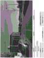
图25示出了包括对道路(右上)、自我车道(左下)和车道实例(右下)的标注的示例道路图像(左上)。尽管车辆下方的道路和车道被遮挡,但车辆下方的道路和车道被标注。未着色的部分没有被标注,即,该类别是未知的。Figure 25 shows an example road image (top left) including annotations for the road (top right), ego lane (bottom left), and lane instances (bottom right). The roads and lanes below the vehicle are labeled although they are occluded. Uncolored parts are not labeled, ie, the class is unknown.
图3示出了车辆300的简化框图,车辆300可以用于捕获待标注的道路图像,即,上面参考图1描述的类型的道路图像。优选地,这些图像被捕获为当车辆300沿着道路行驶时记录的短视频片段的帧,以这样的方式,允许从该片段的帧中重建在记录每个视频片段期间的车辆行驶的路径。车辆300可以被称为训练车辆,作为将其与图2的自主车辆200区分的方便的简写。训练车辆300被示出为包括图像捕获装置302,图像捕获装置302可以是面向前的或面向后的图像捕获装置,并且被耦合到处理器304。处理器304从图像捕获装置302接收所捕获的图像,并将它们储存在存储器306中,可以以下述方式从该存储器中取回图像以供使用。FIG. 3 shows a simplified block diagram of a
在该示例中,车辆300是汽车,但是它可以是任何形式的车辆。In this example,
本发明的基础是假定人类驾驶的训练车辆300行驶的路径沿着道路延伸,且因此可以从训练车辆300采用的任何路径推测道路的位置。当涉及标注所捕获的训练图像序列中的特定图像时,正是训练车辆300在捕获到该图像之后随后所采用的路径的后见之明,使得能够进行自动标注。换句话说,利用所捕获的图像之后车辆行为的后见之明,以便推测图像内道路的位置。因此,标注后的道路位置是预期的并给定的训练车辆300随后行驶的路径和关于这如何与道路的位置相关的潜在假定的道路位置。The invention is based on the assumption that the path traveled by the human-driven
如下面进一步详细描述的,通过处理所捕获的图像本身来确定路径。因此,当用预期道路位置标注特定图像时,对于(对应于面向后的)面向前的图像捕获装置302,在该图像被捕获之后(对应于之前)从车辆行驶的路径确定该图像中的预期道路位置,如使用所捕获的图像序列中的随后(对应于先前)捕获的图像中的至少一个来重建。即,在该图像被标注之后(对应于之前)使用从所捕获的图像中的一个或更多个导出的路径信息来标注被标注的每个图像。As described in further detail below, the path is determined by processing the captured image itself. Thus, when a particular image is annotated with an expected road location, for a forward-facing image capture device 302 (corresponding to rear-facing), the expectation in the image is determined from the path traveled by the vehicle after the image is captured (corresponding to before) The road location, as reconstructed using at least one of a subsequent (corresponding to a previous) captured image in the sequence of captured images. That is, each image that is annotated is annotated using path information derived from one or more of the captured images after the image is annotated (corresponding to before).
3视频标注3 Video Annotation
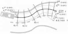
图27示出了在帧i处估计车道边界点


初始标注步骤是自动的,并且提供3D空间中的路面的估计,以及自我车道的估计(参见第3.1章)。然后,手动校正估计,并且进一步在路面空间中添加标注。然后,将标签投影到2D照相机视图中,以允许一次性标注序列中的所有图像(参见第3.2章)。The initial labeling step is automatic and provides an estimate of the road surface in 3D space, as well as an estimate of the ego lane (see Chapter 3.1). The estimates are then manually corrected and further annotations are added in the pavement space. The labels are then projected into the 2D camera view to allow annotation of all images in the sequence at once (see Chapter 3.2).
3.1自动3D自我车道估计3.1 Automatic 3D ego lane estimation
给定来自照相机的N个帧的视频序列,该照相机具有未知的内参数和外参数,目标是确定3D中的路面,并且将自我车道的估计投影到该面上。为此,首先应用文献[28]-一种“来自运动的结构”算法中的OpenSfM来获得全局坐标系中每个帧i∈{1,...,N}的3D照相机位置ci和姿态Ri,以及照相机焦距和畸变参数。Given a video sequence of N frames from a camera with unknown intrinsic and extrinsic parameters, the goal is to determine a road surface in 3D, and project an estimate of the ego's lane onto that surface. To this end, we first apply OpenSfM in [28] - a "structure from motion" algorithm to obtain the 3D camera position ci and pose for each frame i ∈ {1,...,N} in the global coordinate system Ri , and the camera focal length and distortion parameters.
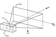
道路被假定为嵌入在3D世界中的2D流形。此外,道路的局部曲率低,因此车轮的定向提供了对局部表面梯度的良好估计。照相机固定在车辆内,具有从当前道路平面的静态平移和旋转(即,假定车身跟随道路平面并且忽略悬架运动)。因此,在帧i处的照相机下方的道路上的地面点gi可计算为Roads are assumed to be 2D manifolds embedded in the 3D world. Furthermore, the local curvature of the road is low, so the orientation of the wheels provides a good estimate of the local surface gradient. The camera is fixed inside the vehicle, with static translation and rotation from the current road plane (ie, the body is assumed to follow the road plane and suspension motion is ignored). Therefore, the ground point gi on the road below the camera at framei can be calculated as
gi=ci+hRingi=ci +hR in
其中h是道路上方的照相机的高度,n是道路相对于照相机的表面法线(参见图26,左)。然后,左自我车道边界和右自我车道边界可被推导为where h is the height of the camera above the road and n is the surface normal of the road relative to the camera (see Figure 26, left). Then, the left ego lane boundary and right ego lane boundary can be derived as

其中,r是道路平面内的矢量,其垂直于行驶方向,
给定帧i,所有未来车道边界Given frame i, all future lane boundaries

可以通过以下公式被投影到局部坐标系中can be projected into the local coordinate system by the following formula

然后,车道标注可被绘制为相邻未来帧的多边形,即具有拐角点Lane labels can then be drawn as polygons of adjacent future frames, i.e. with corner points

这隐含地假定了车道在所捕获的图像之间是分段笔直且平坦的。以下部分描述了如何测量或以其他方式获得以下量:This implicitly assumes that the lanes are segmentally straight and flat between the captured images. The following sections describe how to measure or otherwise obtain the following quantities:
h,n,r,

注意,对于具有相同照相机位置的所有序列,h、n和r仅需要估计一次。Note that h, n and r only need to be estimated once for all sequences with the same camera position.
道路上方的照相机高度ft易于手动测量。然而,在不能完成这个的情况下(例如,对于从web下载的行车记录仪视频),还可以使用从OpenSfM获得的路面的估计网格来获得照相机的高度。对h的粗略估计是足够的,因为它会通过手动标注来校正,参见以下章节。The camera height ft above the road is easy to measure manually. However, in cases where this cannot be done (eg for dashcam videos downloaded from the web), the height of the camera can also be obtained using an estimated mesh of the road surface obtained from OpenSfM. A rough estimate of h is sufficient as it is corrected by manual annotation, see the following sections.
图27示出了在单个帧i处估计道路法线n和前向方向fi的原理,最终估计是所有帧的集合。Figure 27 shows the principle of estimating road normal n and forward direction fi at a single framei , the final estimate being the set of all frames.
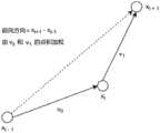
道路法线n是基于以下事实来估计的:当汽车围绕转弯移动时,表示其运动的矢量m将全部位于道路平面中,且因此取其叉积将产生道路法线,参见图27。The road normal n is estimated based on the fact that as the car moves around the turn, the vector m representing its motion will all lie in the road plane, and thus taking its cross product will yield the road normal, see Figure 27.
令mi,j为帧i和j之间的归一化运动矢量,即Let mi,j be the normalized motion vector between frames i and j, i.e.

在帧i处(在照相机坐标中)的估计道路法线是The estimated road normal at frame i (in camera coordinates) is

其中

可以仅在转弯期间估计法线,并且因此该加权方案强调急转弯并且忽略行程的笔直的部分。Normals can be estimated only during turns, and so this weighting scheme emphasizes sharp turns and ignores straight parts of the trip.
r垂直于前向方向f并在道路平面内,因此r is perpendicular to the forward direction f and in the road plane, so

剩余的唯一量是f,其可以通过使用以下事实来导出:The only quantity remaining is f, which can be derived by using the following facts:
如果转弯速率低,则mi-1,i+1近似平行于ci处的切线。因此,可以估计帧i处的前向点If the turn rate is low, thenmi-1, i+1 are approximately parallel to the tangent atci . Therefore, the forward point at frame i can be estimated

(参见图27)。对于正常情况,fi可以在整个行程上被平均以获得更可靠的估计:(See Figure 27). For the normal case, fi can be averaged over the entire trip to get a more reliable estimate:


在这种情况下,根据内积对运动进行加权,以便加重具有低转弯速率的部分,而最大值确保前向运动。In this case, the movement is weighted according to the inner product in order to emphasize the parts with low turn rates, while the maximum value ensures forward movement.
量

为了估计这些,可以假定自我车道具有固定宽度w并且汽车正好在中心行驶,即To estimate these, it can be assumed that the ego lane has a fixed width w and that the car is driving exactly in the center, i.e.


实际上,选择在道路平面内具有许多转弯的序列来估计n,并选择笔直的序列来估计f。然后对于具有相同静态照相机位置的所有序列重新使用相同值。仅标注序列的第一部分,直到从末端开始100m,因为否则不能投影足够的未来车道边界点。在附录A(算法1)中提供了自动自我车道标注程序的概要,并且在图28(见下文)中示出了自动边界点估计的可视化,并且对其进行标注。In practice, a sequence with many turns in the road plane is chosen to estimate n, and a straight sequence is chosen to estimate f. The same value is then reused for all sequences with the same still camera position. Only the first part of the sequence is annotated until 100m from the end, because otherwise not enough future lane boundary points can be projected. A summary of the automatic ego lane labeling procedure is provided in Appendix A (Algorithm 1), and a visualization and labeling of the automatic boundary point estimation is shown in Figure 28 (see below).
下面描述进一步的细节。Further details are described below.
图4示出了图像处理系统的示意性框图,该图像处理系统根据本发明进行操作,以便自动生成用于以上面参考图3所描述的方式所捕获的训练图像的标注数据。该标注数据标记图像内的预期道路位置,其中使用上述假定来推测这些位置。图4A示出了该系统的扩展,其将在下面描述。图4A的系统包括图4的所有部件,并且图4的所有描述同样适用于图4A。FIG. 4 shows a schematic block diagram of an image processing system operating in accordance with the present invention to automatically generate annotation data for training images captured in the manner described above with reference to FIG. 3 . The annotation data marks expected road locations within the image, where these locations are inferred using the assumptions described above. Figure 4A shows an extension of the system, which will be described below. The system of Figure 4A includes all of the components of Figure 4, and all the descriptions of Figure 4 apply equally to Figure 4A.
图5在左手侧示出了由图像捕获系统实现的用于自动图像标注过程的流程图,并且在右手侧示出了对应步骤的示例图示。Figure 5 shows a flow diagram on the left hand side for an automatic image annotation process implemented by an image capture system and an example illustration of the corresponding steps on the right hand side.
现在将并行描述图4和4A的图像系统以及图5的过程。The image systems of FIGS. 4 and 4A and the process of FIG. 5 will now be described in parallel.
图4的图像处理系统被示为包括路径重建部件402、道路建模部件404和图像标注部件406。The image processing system of FIG. 4 is shown to include a
路径重建部件402接收所捕获的二维(2D)图像400的序列,并处理它们以从所捕获的图像序列创建车辆所行驶的路径的三维(3D)重建(步骤502,图5)。
在步骤502的右边,图5示出了三维空间中的两个重建后的路径。To the right of
标记为CP(照相机路径)的第一路径是训练车辆300的图像捕获装置(照相机)302所行驶的路径的3D重建。用于从照相机移动时所捕获的图像序列重建移动照相机所行驶的路径的技术在本领域中是已知的,并且因此在此不进行详细描述。The first path, labeled CP (Camera Path), is a 3D reconstruction of the path traveled by the image capture device (camera) 302 of the
可以从其它数据(加速度计、高度精确的GPS等)重新创建路径,然而,由于基本的行车记录仪而不是包含昂贵的加速度计、昂贵且精确的GPS等的昂贵的汽车就可以用于数据收集,因此仅从视频进行重建有利地使得捕获数据的成本非常便宜。Paths can be recreated from other data (accelerometers, highly accurate GPS, etc.), however, data collection is possible due to a basic dash cam rather than an expensive car containing an expensive accelerometer, expensive and accurate GPS, etc. , so reconstructing only from video advantageously makes the cost of capturing data very cheap.
标记为VP(车辆路径)的第二路径是训练车辆300所行驶的路径的重建,其被定义为由位于训练车辆300的宽度的大约一半(即,与训练车辆的右手侧和左手侧等距)处并且在图像捕获装置300下方的在大约道路水平面的(在图3和3A中标记为P)的点所行驶的路径。即,在道路高度处并沿着车辆300的中心线(C,图3A),该中心线竖直延伸并位于沿着车辆300的宽度的中间点处。The second path, labeled VP (Vehicle Path), is a reconstruction of the path traveled by the
注意,这些点精确等距不是必需的-已经发现该方法即使在这些点不等距时也能给出精确的结果。Note that it is not necessary for the points to be exactly equidistant - this method has been found to give accurate results even when the points are not equidistant.
如果照相机302在道路表面上方的高度(在图3、图3A和图5中标注为H)、照相机302与中心线C的水平偏移(在图3A和图5中标注为S)以及照相机相对于车辆的定向是已知的,则根据照相机路径CP直接确定在地平面处的车辆路径VP。照相机的相对定向可被捕获为如下文定义的“前向点”和“水平线”。If the height of the
注意,图5的右边所示的示例是说明性的,而不是详尽的,并且仅旨在通过示例的方式说明更一般的原理,根据该原理,3D照相机路径CP可以用于使用少量的参考参数来推测道路结构的位置。Note that the example shown on the right side of Figure 5 is illustrative, not exhaustive, and is only intended to illustrate, by way of example, the more general principle according to which the 3D camera path CP can be used to use a small number of reference parameters to infer the location of the road structure.
道路建模部件404根据3D路径重建来创建被假定为车辆已经行驶的道路的3D模型(602,图6)(步骤504,图5)。The
在步骤504的右边所示的示例中,道路模型由对应于假定车道边界位置的两个几何曲线R1、R2形成,两个几何曲线R1、R2被定义为在车辆路径VP的任一侧上平行于车辆路径VP放置并且与车辆路径VP处于相同高度,并且每个几何曲线与车辆路径VP相距距离W/2,其中W是假定的道路宽度或车道宽度。In the example shown to the right of
这是基于这样的假定,即,训练车辆300沿着道路车道行驶,训练车辆300的行驶方向大致平行于该车道的实际车道边界,并且其被行驶在车道的大致中心。This is based on the assumption that the
预期道路位置可例如对应于道路本身的边缘(以便标记道路或道路旁边的不可行驶区域),或对应于道路内的车道位置。The expected road location may, for example, correspond to the edge of the road itself (in order to mark the road or a non-drivable area beside the road), or to the location of the lane within the road.
通常,自动标注技术可以用于标记本文中称为“平行结构”的位置,该“平行结构”即,预期为至少大致平行于由车辆所行驶的路径延伸的结构,或更一般地,预期为相对于车辆路径具有特定定向的预期结构。这可以是道路结构,例如道路、车道、假定平行于车辆路径的不可行驶区域、假定垂直于车辆路径延伸的交叉路口、或者除了汽车之外的车辆可能遇到的真实世界平行结构(例如(在自主无人机、飞机等的情况下的)跑道等)。因此,3D道路模型的所有描述同等地适用于车辆所行驶的环境的任何其他形式的3D结构模型,对于该模型可以使用本文描述的方法自动地确定预期的平行结构。In general, automated labeling techniques may be used to mark locations referred to herein as "parallel structures," ie, structures that are expected to extend at least approximately parallel to the path traveled by the vehicle, or, more generally, are expected to be An expected structure with a specific orientation relative to the vehicle path. This can be road structures such as roads, lanes, non-drivable areas assumed to be parallel to the vehicle path, intersections assumed to extend perpendicular to the vehicle path, or real-world parallel structures that vehicles other than cars may encounter (eg (in in the case of autonomous drones, aircraft, etc.) runways, etc.). Therefore, all descriptions of the 3D road model are equally applicable to any other form of 3D structural model of the environment in which the vehicle travels, for which the expected parallel structure can be automatically determined using the methods described herein.
在平行结构平行于训练车辆300实际行驶的路径的基础假设上,可使用不同的假设来适应不同类型的平行结构。Different assumptions may be used to accommodate different types of parallel structures, based on the assumption that the parallel structures are parallel to the path actually traveled by the
本文中的描述可以具体参考道路或车道,以及诸如道路或车道宽度的相关参数。然而,应当理解,本描述适用于任何平行道路结构,并且对道路或车道宽度(等)的任何参考通常适用于针对预期平行结构确定的宽度参数。The description herein may specifically refer to a road or lane, and related parameters such as the width of the road or lane. It should be understood, however, that this description applies to any parallel road structure, and that any reference to road or lane width (etc.) generally applies to width parameters determined for the intended parallel structure.
图像标注部件406使用3D道路模型来生成2D标注数据,以便用预期的道路位置来单独地标记单独的2D训练图像(步骤506,图5)。
如图5中步骤506的右边所示,通过执行3D道路模型到该图像的平面(标记为I(n))上的几何投影,生成序列中第n个2D图像(图像n,其可以是所捕获的训练图像序列中的任何图像)的标注数据A(n)。在该示例中,这意味着将3D道路边界R1、R2投影到图像平面I(n)上,使得在图像中的那些边界的投影可标记道路边界被假定位于图像n中的何处。As shown to the right of
图像平面I(n)是与捕获图像n时照相机302的视场相对应的平面,并且因此位于与捕获图像n时车辆的位置相对应的点处。Image plane I(n) is the plane corresponding to the field of view of
参数计算部件408计算用于从重建的车辆路径构建3D模型并执行几何投影的各种“参考参数”。这些参考参数包括与训练车辆300的图像捕获装置302的位置和定向有关的以下图像捕获参数:The parameter calculation component 408 calculates various "reference parameters" for constructing a 3D model from the reconstructed vehicle path and performing geometric projection. These reference parameters include the following image capture parameters related to the position and orientation of the
1)道路上方的照相机302的高度H;1) The height H of the
2)照相机与中心线C的水平偏移S;2) The horizontal offset S of the camera and the center line C;
3)照相机302相对于车辆的定向,其可以被捕获为:3) The orientation of the
a.照相机302的“前向点”(如下所定义),以及a. the "forward point" of the camera 302 (as defined below), and
b.照相机的“水平线”(如下定义);b. the "horizontal line" of the camera (as defined below);
以及:as well as:
4)道路/车道的宽度W。4) The width W of the road/lane.
这些以上面简要描述的方式使用,并且下面描述如何使用它们的计算的进一步细节。现在只要说明这些参数是从所捕获的训练图像400本身计算的就足够了,其具有后面描述的各种益处。These are used in the manner briefly described above, and further details of the calculations on how to use them are described below. It is now sufficient to state that these parameters are calculated from the captured
标注数据被储存在电子存储器414中,从该电子存储器414可以访问或取回标注数据以用于以上参考图1描述的训练过程。在该过程中,最后,自动结构检测部件102从人类驾驶员的能力中学习,以在捕获训练图像时的大多数时间将车辆300保持在大约道路中心处。The annotation data is stored in
3.2手动校正和附加标注3.2 Manual correction and additional annotation
标注界面向人类标注员提供单独地批量查看帧的能力,同时将当前呈现的车道投影到图像中。这些车道可以在最方便的帧中被标注员加宽、变窄和移动,并且对车道结构的这些改变将被投影到该批量中的所有其他帧中,从而提供了优于单独标注所有图像的明显优点。The annotation interface provides human annotators with the ability to batch view frames individually, while projecting the currently rendered lanes into the image. These lanes can be widened, narrowed, and moved by the annotator in the most convenient frame, and these changes to the lane structure will be projected into all other frames in the batch, providing an advantage over annotating all images individually Obvious advantage.
图28示出了从上方看到的自我车道估计的可视化。自动估计和手动校正分别被标记为Figure 28 shows a visualization of the ego lane estimate seen from above. Automatic estimation and manual correction are marked as
wileft(自动的)wileft (automatic)
wileft(手动的)。wileft (manual).
最初,所有的


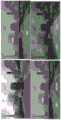
图18至24示出了由标注员使用的标注界面的示例。在图18中,在图像的中心,可以看到自我路径投影到该帧中。在左下,标注员被提供有控件以操纵当前呈现的车道(变窄、加宽、向左或向右移动、移动车道的边界等)并添加新的车道。在图19中,标注员有用于调整照相机高度以使重建与路面匹配以及调整作物高度以排除车辆仪表板或引擎盖的工具。所有标注都在估计的3D道路平面中执行,但经由2D照相机视图中的投影提供即时反馈。标注员可以在序列中容易地向前和向后跳读,以确定标签是否与图像对准,并且如果需要的话校正它们。图27中示出了校正后序列的示例(参见上文)。18 to 24 show examples of annotation interfaces used by annotators. In Figure 18, in the center of the image, the ego path can be seen projected into the frame. In the bottom left, the annotator is provided with controls to manipulate the currently rendered lane (narrow, widen, move left or right, move the boundaries of the lane, etc.) and add new lanes. In Figure 19, the annotator has tools for adjusting the camera height to match the reconstruction to the road surface and adjusting the crop height to exclude the vehicle dashboard or hood. All annotations are performed in the estimated 3D road plane, but provide immediate feedback via projections in the 2D camera view. Annotators can easily skip forward and backward in the sequence to determine if the labels are aligned with the image, and correct them if necessary. An example of a corrected sequence is shown in Figure 27 (see above).
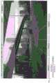
除了道路上的车道之外,由附图标记NR1指示的沿道路侧面的条带被标注为“非道路”。此外,每个图像的整个上部(顶部条带NR2)被标注为非道路,其中大小由标注员手动调整。图25示出了所呈现的标注的示例。In addition to the lanes on the road, the strip along the side of the road, indicated by the reference numeral NR1, is labeled "non-road". Furthermore, the entire upper part of each image (top strip NR2) is annotated as non-roads, where the size is manually adjusted by the annotator. Figure 25 shows an example of the annotations presented.
以上在图4A的扩展中实现,其中设置有呈现部件416,该呈现部件416可以经由用户界面(UI)412呈现用针对该图像确定的预期道路标注标记的单独训练图像(图像n)。因此,用户可以检查预期道路结构与图像中可见的实际道路结构有多紧密对应,并且在必要时进行校正。The above is implemented in an extension of Figure 4A, where a
UI 412的输出被示出为经由连接器418连接到图像标注部件的输入,以指示用户可以经由UI 412修改单独图像的标注数据A(n),以便将假定的车道边界R1、R2与(仅)该图像中的实际车道边界更好地对准。这对于适应例如由不寻常的局部道路结构引起的“一次性”差异是有用的。The output of the
还设置有模型适配部件410以允许经由UI 412同时跨多个图像对标注数据进行高效的手动适配。这通过允许用户参考单个图像及其所呈现的标注数据来适配3D道路模型以便更好地对准该图像中的道路边界来起作用。然而,因为3D道路模型(而不是仅仅单独图像的标注数据A(n))正被适配,所以这些适配也可以应用于其他图像的标注数据,而用户不必手动地适配那些其他图像的标注数据。例如,用户可以适配假定的车道宽度W以更好地适合一个图像,并且因为道路模型被适配到新的车道宽度,所以可以基于具有新的车道宽度W的适配后的模型来自动适配其他图像的标注数据。A model
图4和4A的图像处理系统的上述部件是图像处理系统的功能部件,表示由图像处理系统执行的功能。这些功能以软件实现,即通过储存在存储器中并由图像处理系统(未示出)的一个或多个处理器执行的可执行指令(代码)实现,这些功能可以由一个或更多个通用处理单元(例如CPU)、更专用的处理单元(例如GPU)或其任意组合形成。如将理解的,这些部件表示高级功能,其可使用各种代码结构来实现。图4中的箭头一般指示这些高级功能之间的高级相互关系,并且不必对应于物理连接或逻辑连接的任何特定布置。图5的步骤是计算机实现的步骤,当指令在一个或更多个处理器上执行时,指令使图像处理系统执行这些步骤。The above-described components of the image processing system of FIGS. 4 and 4A are functional components of the image processing system, representing functions performed by the image processing system. These functions are implemented in software, that is, by executable instructions (code) stored in memory and executed by one or more processors of an image processing system (not shown), and these functions may be processed by one or more general-purpose A unit (eg, a CPU), a more specialized processing unit (eg, a GPU), or any combination thereof. As will be appreciated, these components represent high-level functionality, which can be implemented using various code structures. The arrows in Figure 4 generally indicate high-level interrelationships between these high-level functions, and do not necessarily correspond to any particular arrangement of physical or logical connections. The steps of FIG. 5 are computer-implemented steps that, when executed on one or more processors, the instructions cause an image processing system to perform the steps.
示例实现的细节:Details of the example implementation:
图13示出了带标注的图像的示例,在图13中,标记了两条可行驶的车道:朝向图像中间的自我车道,以及图像左边的另一可行驶车道。在这些车道的任意侧标记两个不可行驶的区域,如在最右侧的另一方向上行驶的交通的车道由不可行驶的区域中的一个与自我车道分离。An example of an annotated image is shown in Figure 13, where two drivable lanes are marked: the ego lane towards the middle of the image, and the other drivable lane to the left of the image. Two non-drivable areas are marked on either side of these lanes, eg a lane of traffic traveling in the other direction on the far right is separated from the ego lane by one of the non-drivable areas.
如上所述,该方法采用了以下观察和假定:As mentioned above, the method employs the following observations and assumptions:
1)当人类驾驶汽车时,他们通常遵循保持靠近道路上的车道中心的路径。因此,如果视频照相机面向前(或替代地,向后)放置在人类驾驶的汽车中,那么当照相机向下投射到地面上并扩展到车道的宽度时,照相机所追踪出的路径将(主要)勾勒出车道所在的位置。1) When humans drive a car, they usually follow a path that stays close to the center of the lane on the road. So, if the video camera is placed in a human-driven car facing forward (or, alternatively, backward), the path traced by the camera will be (mainly) Outline where the driveway will be.
2)在找到车道所在位置的轮廓之后,然后对于视频中的每个图像,汽车下方的车道的该轮廓可以被投影回图像中并且(几乎)精确地提供标记车道位置所需的标注。2) After finding the contour of where the lane is, then for each image in the video, this contour of the lane under the car can be projected back into the image and provide (almost) precisely the annotations needed to mark the lane's position.
本发明的优选实施例利用低成本设备实现这一点,如稍后所解释的。Preferred embodiments of the present invention achieve this with low cost equipment, as explained later.
确定路径和参考参数:Determine the path and reference parameters:
为了生成车道位置并将其投射回每个图像,如上所述,需要知道或推测以下内容:In order to generate the lane positions and project them back into each image, as described above, the following needs to be known or inferred:
·照相机302遵循的3D空间中的路径(CP,图5);the path in 3D space followed by the camera 302 (CP, Figure 5);
·汽车300内的照相机302的定向,其可以使用以下参数表示:The orientation of the
ο前向点,其被定义为当汽车沿直线行驶时汽车看起来朝向其行驶的像素,ο the forward point, which is defined as the pixel towards which the car appears to be heading when the car is driving in a straight line,
ο水平线,其被定义为图像上看起来平行于道路的线;ο horizontal lines, which are defined as lines on the image that appear to be parallel to the road;
·路面上方照相机的高度(H,图3,3A和5)The height of the camera above the road surface (H, Figures 3, 3A and 5)
·汽车内照相机的左/右位置(在图3A和5中作为间隔S捕获);以及the left/right position of the camera in the car (captured as interval S in Figures 3A and 5); and
·车道的宽度(W,图3A和5)。• The width of the lane (W, Figures 3A and 5).
下面描述的图像处理技术允许利用廉价的和未校准的设备来确定所有上述内容,所述设备例如是花费几百英镑的移动电话或行车记录仪,或者其他低成本的消费设备。这是因为可以使用下面描述的图像处理技术从由训练车辆300捕获的图像来计算它们。The image processing techniques described below allow all of the above to be determined using inexpensive and uncalibrated equipment, such as mobile phones or dash cams costing several hundred pounds, or other low cost consumer equipment. This is because they can be computed from the images captured by the
3)可以通过使用现有的视觉SLAM(同时定位与建图)技术对来自未校准的照相机的所捕获的视频进行后处理来推测照相机的3D路径CP。诸如OpenSFM和ORB-SLAM的软件包可以用于生成精确的照相机路径信息。3) The camera's 3D path CP can be inferred by post-processing the captured video from the uncalibrated camera using existing visual SLAM (simultaneous localization and mapping) techniques. Software packages such as OpenSFM and ORB-SLAM can be used to generate accurate camera path information.
这样的技术可以用于构建训练车辆300所行驶的环境的3D地图,同时同步地跟踪该环境内的车辆的位置。Such techniques can be used to construct a 3D map of the environment in which the
基于图像的SLAM的一些基本原理通过参考图7的示例被简要地说明。图7的顶部示出了在不同时间和从不同但接近的位置捕获的真实世界环境的三个图像-img(n-1)、img(n)和img(n+1)。通过识别出现在图像中的区别性参考特征(例如,标注为F1和F2的那些),并将它们跨图像进行匹配,然后可以使用三角测量来构建这些特征的3D模型,如图7的下部所示。对于捕获的图像img(n-1)、img(n)和img(n+1)中的每一个,估计捕获图像时照相机302的3D位置(分别标注为xn-1,xn,xn+1),作为3D空间内照相机的视场的定向。对于图像img(n-1)、img(n)、img(n+1)中的每一个,相应的图像平面I(n-1)、I(n)、I(n+1)被定义为在距照相机位置xn-1,xn,xn+1任意非零距离处垂直于并且相交于捕获该图像时照相机的视场的平面。基于应用于参考特征F1和F2的光线跟踪原理来选择相机位置和定向,使得对于相机位置xn-1,xn,xn+1中的每个,从参考特征F1、F2中的每个到该照相机位置的光线(直线)在至少近似对应于参考特征在相应图像中出现的位置(即,该特征在图像内的像素位置)的位置处与相应图像平面I(n-1),I(n),I(n+1)相交。然后,可以从得到的照相机位置xn-1,xn,xn+1的序列来重建相机路径CP。Some basic principles of image-based SLAM are briefly explained by referring to the example of FIG. 7 . The top of Figure 7 shows three images of the real world environment - img(n-1), img(n) and img(n+1) captured at different times and from different but close locations. By identifying the distinguishing reference features that appear in the image (for example, those labeled F1 and F2) and matching them across the images, triangulation can then be used to build a 3D model of these features, as shown in the lower part of Figure 7 Show. For each of the captured images img(n-1), img(n ), and img(n +1), estimate the 3D position of the
注意,作为SLAM过程的一部分而构建的该3D模型不同于由建模部件404构建的3D模型。前者是基于图像三角测量构建的表面图的形式,而后者表示基于车辆路径推测的预期结构,该车辆路径又从在执行SLAM过程中导出的图像捕获装置位置来确定。Note that this 3D model built as part of the SLAM process is different from the 3D model built by
参考图7A和7B,可以使用俯仰(P')、滚转(R')和偏航(Y')角来表示照相机302的3D定向。纵轴aL′可以方便地被定义为平行于照相机的光轴,横轴和竖轴a′T,aV′对应于图像平面内的水平和竖直定向(即,对应于在所捕获的图像中表现为水平和竖直的方向),照相机的俯仰P'、滚转R'和偏航Y'分别定义为围绕照相机的横轴、纵轴和竖轴aT′、a′L、aV′(照相机轴)的角度。这里使用矢量符号,aT′、a′L、aV′是在相应轴的方向上的单位矢量。根据这个定义,图像平面I(n)垂直于照相机的横轴,并且与横/竖照相机轴水平地/竖直地对准。7A and 7B, pitch (P'), roll (R'), and yaw (Y') angles may be used to represent the 3D orientation of
这种SLAM技术实际上确实生成环境的表面重建。虽然理论上这种表面重建可以用于直接确定道路/车道位置,但是通常表面重建的质量在实践中不足以这样做。然而,照相机通过3D场景的运动质量良好,并且因此提供了照相机路径CP的足够准确的重建(这是因为照相机位置基于数百个特征点,而表面位置仅基于少量特征点),这又允许使用本技术以足够的准确性来推测道路/车道位置。This SLAM technique actually does generate a surface reconstruction of the environment. While in theory such surface reconstructions can be used to directly determine road/lane locations, usually the quality of surface reconstructions is not sufficient to do so in practice. However, the motion of the camera through the 3D scene is of good quality and thus provides a sufficiently accurate reconstruction of the camera path CP (this is because the camera position is based on hundreds of feature points, while the surface position is based on only a few), which in turn allows the use of The present technique guesses the road/lane position with sufficient accuracy.
注意,这些技术中的一些还可以自动地推测出诸如焦距甚至透镜畸变参数的相机特性。这些参数可以被用来优化本技术,但它们不是必需的。Note that some of these techniques can also automatically infer camera characteristics such as focal length and even lens distortion parameters. These parameters can be used to optimize the technique, but they are not required.
图14示出了移动通过点云世界的照相机位置的SLAM重建的示例图像,标注为1400的金字塔结构序列表示拍摄不同图像时图像捕获装置的位置和定向,如经由SLAM过程所估计的。这些共同地限定了照相机路径CP。标注为1402的块构成作为SLAM过程的一部分而生成的3D表面图。这两个方面将在后面更详细地描述。Figure 14 shows an example image of a SLAM reconstruction of a camera position moving through a point cloud world, the sequence of pyramid structures labeled 1400 represents the position and orientation of the image capture device when different images were taken, as estimated via the SLAM process. These collectively define the camera path CP. The block labeled 1402 constitutes the 3D surface map generated as part of the SLAM process. These two aspects will be described in more detail later.
剩余的参考参数由参数计算部件408经由图像处理来计算,如下所述。首先,简要介绍一些基本的考虑。The remaining reference parameters are calculated by the parameter calculation section 408 via image processing, as described below. First, some basic considerations are briefly introduced.
参考图8,可以以与照相机相同的方式定义训练车辆300的3D定向。这里,车辆的俯仰、滚转和偏航分别标记为P、R和Y,并且训练车辆的横轴、纵轴和竖轴(车辆轴)分别由单位矢量aT,aL,aV表示。纵轴对应于车辆在直线行驶时的行驶方向(前向方向)。竖轴是垂直于路面(即,垂直于车轮与道路之间的接触点所在的平面)的方向。横轴沿着车辆300的宽度延伸,垂直于纵轴和竖轴。Referring to Figure 8, the 3D orientation of the
注意,除非另外指出,否则本文中使用的术语“绝对”是指车辆行驶的环境中的定向和位置。即,相对于车辆在其中移动的环境的全局参考系的(任意)全局坐标系而定义的。这可以被定义为SLAM过程的固有部分。这是定义了重建后的车辆路径、图像捕获装置在环境中的定向(绝对定向)和表面重建的坐标系。Note that the term "absolute" as used herein refers to the orientation and position in the environment in which the vehicle is traveling, unless otherwise indicated. That is, defined relative to an (arbitrary) global coordinate system of the global reference frame of the environment in which the vehicle is moving. This can be defined as an inherent part of the SLAM process. This is the coordinate system that defines the reconstructed vehicle path, the orientation of the image capture device in the environment (absolute orientation) and the surface reconstruction.
术语“相对”用于指相对于车辆的位置和定向,即相对于车辆的坐标系限定的位置和定向,例如由车辆轴aT,aL,aV限定的坐标系。The term "relative" is used to refer to a position and orientation relative to the vehicle, ie a position and orientation defined relative to a coordinate system of the vehicle, eg a coordinate system defined by vehicle axes aT , aL , aV .
参考图9,该方法不需要照相机302的定向与训练车辆300的定向完全对准。照相机轴相对于车辆轴的角度失准是可接受的,因为这种失准可以使用下面描述的技术来检测和解决。Referring to FIG. 9 , the method does not require the orientation of the
4)照相机在汽车内的角度定向,即照相机的纵轴aL′和车辆的纵轴aL(即,如在图像捕获装置的参考系内(即在图像捕获装置的定向保持固定的参考系内)测量的车辆的纵轴aL)之间的角度偏移,可以通过利用当汽车直线行驶时汽车的运动矢量将平行于汽车车身(即,车辆的纵轴)的事实自动地推导,并且因此可以计算照相机相对于汽车车身的定向。该定向被捕获为照相机的前向点,该前向点被定义为汽车在直线行驶时看起来朝向的像素(如上所述)。4) The angular orientation of the camera within the car, i.e. the longitudinal axis aL ′ of the camera and the longitudinal axis aL of the vehicle (i.e. as in the frame of reference of the image capture device (i.e. in the frame of reference in which the orientation of the image capture device remains fixed) ), the angular offset between the longitudinal axes aL ) of the vehicle, measured in a straight line, can be automatically derived by exploiting the fact that the motion vector of the car will be parallel to the car body (ie, the longitudinal axis of the vehicle) when the car is traveling in a straight line, and The orientation of the camera relative to the vehicle body can thus be calculated. This orientation is captured as the camera's forward point, which is defined as the pixel that the car appears to be facing when driving in a straight line (as described above).
不可能依赖于存在其中汽车以完全直线的方式行驶的视频部分。为了克服汽车永远不能以完全直线的方式行驶的事实,采用以下方法。It is not possible to rely on the existence of a video portion where the car is driving in a perfectly straight line. To overcome the fact that a car can never drive in a perfectly straight line, the following approach is employed.
在路径上取三个等距点,将外面的两个点连接起来,并且将该矢量用作中心点处的前向方向的近似。该方法通过中心点和两个外部点之间的矢量的点积连续地加权平均。因此,车辆接近直线行驶的时间比汽车转弯的时间的权重要大得多。使用这种方法可以产生子像素精度。Take three equidistant points on the path, connect the two outer points, and use this vector as an approximation for the forward direction at the center point. This method is continuously weighted by the dot product of the vectors between the center point and the two outer points. Therefore, the time when the vehicle is traveling close to a straight line is much more weighted than the time when the car is turning. Using this method yields sub-pixel precision.
这在图15中示出。This is shown in FIG. 15 .
换句话说,这利用了当车辆300沿(近似)直线行驶时矢量差xt+1-xt-1In other words, this takes advantage of the vector difference xt+1 -xt-1 when the
(近似)平行于车辆的纵轴aL的观察结果,以便估计照相机302相对于车辆300的角度偏移。这是通过向更线性(直线)运动的间隔分配更大的权重而在加权平均中捕获的。An observation (approximately) parallel to the longitudinal axis aL of the vehicle in order to estimate the angular offset of the
注意,严格地说,只要转弯速率近似恒定(实际上不需要车辆沿直线行驶),矢量差xt+1-xt-1近似平行于车辆纵轴。然而,当车辆更接近沿直线行驶时,近似恒定的转弯速率的假定将更可能是正确的。Note that, strictly speaking, as long as the turn rate is approximately constant (actually the vehicle is not required to travel in a straight line), the vector difference xt+1 - xt-1 is approximately parallel to the vehicle longitudinal axis. However, the assumption of an approximately constant rate of turn will be more likely to be true as the vehicle moves closer to a straight line.
计算作为矢量平均值来执行,其中矢量表示如在照相机坐标系中表示的汽车的平均前向运动。当向前投影时,该矢量将在特定像素(前向点像素)处切割图像平面。该像素是如果汽车在完全笔直且平坦的道路上行驶,则汽车看起来将向其移动的点(如在此使用的术语“前向点”)。The calculation is performed as a vector average, where the vector represents the average forward motion of the car as represented in the camera coordinate system. When forward projected, this vector will slice the image plane at a specific pixel (forward point pixel). This pixel is the point to which the car would appear to be moving if it were driving on a perfectly straight and flat road (as the term "forward point" is used herein).
例如,车辆的前向方向可以作为照相机纵轴和车辆的纵轴之间的矢量差的加权平均,分别根据等式1来计算:For example, the forward direction of the vehicle can be taken as a weighted average of the vector differences between the longitudinal axis of the camera and the longitudinal axis of the vehicle, calculated according to

其中,如在时间t所评估的,wL,t=v0·v1。where, as evaluated at time t, wL,t = v0 ·v1 .
假定在时间t车辆纵轴aL平行于矢量差xt+1-xt-1。It is assumed that at time t the vehicle longitudinal axis aL is parallel to the vector difference xt+1 - xt-1 .
注意,在这种情况下,需要在图像捕获装置302的参考系中评估xt+1-xt-1,以便给出有意义的结果,即,以便使等式(1)的加权平均提供车辆的纵轴aL相对于照相机的纵轴a′L的方向的准确估计。Note that in this case, xt+1 -xt-1 needs to be evaluated in the frame of reference of the
SLAM过程将导出xt+1和xt-1的绝对值,即在全局坐标系中。然而,全局坐标系中的照相机轴的方向,即图像捕获装置的绝对定向,在时间t也经由SLAM过程本身导出,SLAM过程本身又可以用于将全局参考系中的矢量变换至图像捕获装置302的参考系。The SLAM process will derive the absolute values ofxt+1 andxt-1 , i.e. in the global coordinate system. However, the orientation of the camera axis in the global coordinate system, ie the absolute orientation of the image capture device, is also derived at time t via the SLAM process itself, which in turn can be used to transform the vector in the global reference frame to the
点积v0·v1取决于t-1和t+1之间的方向变化的大小,使得方向大小的变化越小,在时间t给予测量的权重越大。The dot product v0 · v1 depends on the magnitude of the directional change between t-1 and t+1, such that the smaller the change in directional magnitude, the more weight is given to the measurement at time t.
如上所述,严格地说,只要转弯速率近似恒定(实际上不需要车辆沿直线行驶),矢量差xt+1-xt-1近似平行于车辆纵轴。因此,可以使用替代的加权方案,其中根据在t-1和t+1之间的车辆路径中呈现的曲率变化来加权每个时间的矢量差。As mentioned above, strictly speaking, as long as the turn rate is approximately constant (actually it is not necessary for the vehicle to travel in a straight line), the vector difference xt+1 - xt-1 is approximately parallel to the vehicle longitudinal axis. Therefore, an alternative weighting scheme may be used in which the vector difference at each time is weighted according to the change in curvature present in the vehicle path between t-1 and t+1.
当然,通常当车辆移动时,车辆轴的定向在图像捕获装置的参考系中保持固定,因为照相机302被预期相对于车辆300保持在基本固定的定向,以上的时间依赖性源于车辆和照相机轴的估计不精确的事实。Of course, generally when the vehicle is moving, the orientation of the vehicle axis remains fixed in the frame of reference of the image capture device, since the
时间t对应于照相机路径CP上的特定点,且可为所捕获图像中的一个的时间或所捕获图像之间的时间,可通过不同图像的照相机姿态的插值将照相机姿态分配给所述时间。The time t corresponds to a particular point on the camera path CP and can be the time of one of the captured images or the time between captured images to which the camera poses can be assigned by interpolation of the camera poses of the different images.
在替代实施方案中,aL和aL′之间的偏移可表示为一对角度。In alternative embodiments, the offset between aL and aL ' may be expressed as a pair of angles.
参考图10,一旦以这种方式计算了照相机302相对于车辆300的角度定向,则可以基于照相机的纵轴a′L在该点的定向确定车辆的纵轴aL在沿着照相机路径CP的任何点处(包括当车辆不以直线行驶时)的定向,这从SLAM计算中已知。Referring to Figure 10, once the angular orientation of
5)通过注意到大多数道路是局部平坦的,可以自动推导出汽车内的照相机的旋转定向,即照相机的竖轴aV′与车辆的竖轴aV(即,在图像捕获装置的参考系内测量的车辆的竖轴)之间的旋转偏移,因此当车辆转弯时,垂直于由照相机路径描述的表面的矢量将从照相机直接向下指向路面。更详细地,再取路径上的三个等距点(尽管再次,但这些点不是必需是等距的),采用从中心到两个外部点的两个矢量的叉积,并且通过叉积的大小对其进行连续加权平均。因此,汽车以曲线行驶的时间比汽车直线行驶的时间(在该点处不存在关于法线的信息)被更强地加权。5) By noticing that most roads are locally flat, the rotational orientation of the camera in the car can be automatically deduced, ie the vertical axis aV ′ of the camera is related to the vertical axis aV of the vehicle (ie, in the frame of reference of the image capture device) A rotational offset between the vehicle's vertical axis), so when the vehicle turns, a vector normal to the surface described by the camera's path will point directly down the road from the camera. In more detail, take three equidistant points on the path (though again, these points do not have to be equidistant), take the cross product of the two vectors from the center to the two outer points, and pass the cross product of the A continuous weighted average of its size. Therefore, the time the car is traveling in a curve is weighted more strongly than the time the car is traveling in a straight line (at which point there is no information about the normal).
这在图16中示出。This is shown in FIG. 16 .
换句话说,这利用了以下观察,即,当车辆呈现角加速度使得车辆路径在3D空间中呈现局部曲率时,车辆路径的弯曲部分所在的平面在正常驾驶条件下至少大致平行于路面的平面;或者等效地,路径的局部弯曲部分的法线至少大致平行于车辆300的竖轴aV。In other words, this exploits the observation that, when the vehicle exhibits angular acceleration such that the vehicle path exhibits local curvature in 3D space, the plane of the curved portion of the vehicle's path is at least approximately parallel to the plane of the road surface under normal driving conditions; Or equivalently, the normal to the locally curved portion of the path is at least approximately parallel to the vertical axis aV of the
在照相机坐标中表示路径的平均法向矢量。垂直于该路面法向矢量的平面可以与图像平面相交,并且这将提供跨过图像的线,如果汽车沿着完全笔直的和水平的道路行驶,则该线将匹配地平线(如在本文中使用的术语"水平线")。The mean normal vector representing the path in camera coordinates. A plane perpendicular to this road normal vector can intersect the image plane, and this will provide a line across the image that would match the horizon if the car were traveling along a perfectly straight and level road (as used in this paper). the term "horizontal line").
例如,车辆内的照相机的旋转定向可以根据等式(2)分别计算为照相机和车辆的竖轴之间的偏移角的加权平均值:For example, the rotational orientation of a camera within a vehicle can be calculated as a weighted average of the offset angles between the camera and the vertical axis of the vehicle, respectively, according to equation (2):

其中:in:
·如在时间t所评估的,wV,t=|v0×v1|,wV,t = |v0 ×v1 |, as evaluated at time t
·v0=xt-xt-1,v0 =xt -xt-1 ,
·v1=xt+1-xt。· v1 =xt+1 −xt .
假设时间t处的车辆竖轴aV与矢量叉积v0×v1平行。Assume that the vehicle vertical axis aV at time t is parallel to the vector cross product v0 ×v1 .
如上所述,在这种情况下,需要在图像捕获装置302的参考系中评估v0×v1,以便给出有意义的结果,即,以便使等式的加权平均提供车辆的竖轴aV相对于照相机的纵轴a′L的方向的准确估计。如上所述,经由SLAM过程确定的图像捕获装置的绝对定向可用于将矢量从全局参考系变换到图像捕获装置的参考系。As mentioned above, in this case, v0 ×v1 needs to be evaluated in the frame of reference of the
当组成矢量朝垂直方向移动时,叉积|v0×v1|的大小增加,如预期地产生最准确的结果。更一般地,它们通过随着这些矢量之间的偏移角α趋向九十度而增加的因子来加权,其中|v0×v1|=|v0||v1|sinα。The magnitude of the cross product |v0 ×v1 | increases as the constituent vectors move in the vertical direction, yielding the most accurate results as expected. More generally, they are weighted by a factor that increases as the offset angle α between these vectors approaches ninety degrees, where |v0 ×v1 |=|v0 ||v1 |sinα.
如将理解的,以上关于角度定向测量所进行的许多观察也适用于旋转定向测量。As will be appreciated, many of the observations made above with respect to angular orientation measurements also apply to rotational orientation measurements.
6)通过从SLAM过程生成道路的表面网格(即使这是低精度的),然后对该网格上方的在照相机路径上的所有点的高度求平均,可以计算道路上方的照相机的高度(H)。在整个路径上的平均抵消了由SLAM过程产生的网格的低精度。6) The height of the camera above the road can be calculated (H ). Averaging over the entire path offsets the low precision of the meshes produced by the SLAM process.
在照相机路径CP上的给定点处的高度H被定义为照相机路径CP上的点与在该点处沿着车辆的竖轴aV的网格之间的距离。需要车辆300内的照相机302的旋转定向的原因是为了确定车辆的竖轴位于路径上的每个点处的位置,使得可以计算高度估计。这在图11中示出,其中重建的表面图被标记为SM。The height H at a given point on the camera path CP is defined as the distance between a point on the camera path CP and the grid at that point along the vertical axis aV of the vehicle. The reason the rotational orientation of the
7)通过使用各种计算机视觉技术来检测车道边界,可以估计车道内照相机的从左到右的位置(S)以及车道的宽度(W)。7) By using various computer vision techniques to detect the lane boundaries, the left-to-right position (S) of the cameras in the lane and the width (W) of the lane can be estimated.
检测车道边缘显然是个难题(并且生成该车道训练数据的整体目的是训练神经网络以解决该问题)。然而,由于具有两条附加信息,在这种特定情况下检测车道边缘可以成为显著地更容易的问题。首先,照相机的已知路径(以及因此车道的形状)可以用于创建变换,以在进行任何车道边界检测之前有效地使道路变直。其次,搜索车道边界的位置显著减少,因为车道的中心线(几乎)从照相机路径已知,并且车道具有相对固定的宽度。Detecting lane edges is obviously a difficult problem (and the whole purpose of generating training data for that lane is to train a neural network to solve that problem). However, with two additional pieces of information, detecting lane edges can be a significantly easier problem in this particular case. First, the known path of the camera (and thus the shape of the lane) can be used to create a transform to effectively straighten the road before any lane boundary detection is done. Second, the locations of the search lane boundaries are significantly reduced, since the centerlines of the lanes are (almost) known from the camera path, and the lanes have relatively fixed widths.
例如,图像可以被投影到自顶向下的视图中,被变换以(使用相机路径信息)使道路变直,并且然后可以使用霍夫变换来检测具有正确近似位置和定向的主线。For example, the image can be projected into a top-down view, transformed to straighten the road (using camera path information), and then a Hough transform can be used to detect main lines with the correct approximate position and orientation.
在相机路径CP上的每个点处的道路宽度被定义为在该点处沿横车辆轴aT的检测车道边界之间的距离。除了旋转定向之外,还需要确定在训练车辆300内的照相机302的角定向的原因是为了确定车辆的横轴aT位于何处,以便估计在沿着路径的每个点处的W和C。这也在图11中示出。The road width at each point on the camera path CP is defined as the distance between the detected lane boundaries along the transverse vehicle axis aT at that point. In addition to the rotational orientation, the reason the angular orientation of the
通过利用所有上述内容,可以仅使用从低成本且未校准的图像捕获装置所捕获的图像,在视频的所有图像中完全自动地生成由汽车行驶的车道的标注。By taking advantage of all of the above, it is possible to fully automatically generate annotations of lanes driven by cars in all images of the video, using only images captured from low cost and uncalibrated image capture devices.
还希望将这些技术扩展到标注多个车道。这样做的一种方式如下:It is also desirable to extend these techniques to label multiple lanes. One way of doing this is as follows:
8)通过沿每个车道行驶并创建包括每个车道的路径的单个3D SLAM重建,可以自动标注多个车道(以及因此整个路面)。有必要将沿着每条线行驶的单独视频合并到单个重建中,以便获得车道和整个路面的相对定位。8) Multiple lanes (and thus the entire road surface) can be automatically annotated by driving along each lane and creating a single 3D SLAM reconstruction of the path that includes each lane. It is necessary to merge the separate videos of driving along each line into a single reconstruction in order to obtain the relative localization of the lane and the entire road surface.
图17示出了移动通过点云世界的相机位置的SLAM重建的图像,其中存在两组照相机图像。Figure 17 shows a SLAM reconstructed image of a camera position moving through a point cloud world, where there are two sets of camera images.
9)难以将来自多个视频的图像合并到单个3D重建中,除非照相机图像全部面向相同方向;即,将沿着道路在相反方向上行驶的汽车的视频合并到单个3D重建中是不实际的。解决这个问题的一种方法是采用面向前的照相机在一个方向上行驶,并且使用面向后的照相机在另一个方向上(在另一个车道上)行驶。这给出了全部指向沿着道路的相同方向的单组图像。9) It is difficult to combine images from multiple videos into a single 3D reconstruction unless the camera images are all facing the same direction; i.e. it is not practical to combine videos of cars driving in opposite directions along the road into a single 3D reconstruction . One way to get around this is to drive in one direction with a forward-facing camera and in the other direction (in another lane) with a rear-facing camera. This gives a single set of images all pointing in the same direction along the road.
扩展-人类修正阶段:Extended - Human Correction Phase:
所描述的全自动标注系统产生可用的标注,然而,它仍然有许多错误,而这些错误可以由人类标注员以非常小的努力来修正。例如:The described fully automatic annotation system produces usable annotations, however, it still has many errors that can be corrected by human annotators with very little effort. E.g:
·计算出的照相机高度可能不是正好正确的The calculated camera height may not be exactly correct
·车道内的左/右位置可能不是正好正确的· The left/right position in the lane may not be exactly correct
·车道的宽度可能不是正好正确的the width of the lane may not be exactly right
除了针对这些不完美的自动计算的修正之外,还有一些人们可以添加的附加标注,添加这些标注的工作量非常少,但是如果它们存在于训练数据中,则提供了显著的益处。例如:In addition to corrections for these imperfect automatic calculations, there are additional annotations that people can add that are very minimal effort, but provide significant benefit if they are present in the training data. E.g:
·可以添加相邻的车道(不必行驶这些车道)。它们易于添加,因为相邻车道通常具有与汽车已经行驶的车道平行的边界。· Adjacent lanes can be added (these lanes do not have to be driven). They are easy to add because adjacent lanes often have borders parallel to the lane the car is already driving on.
·可以添加不可行驶的平行道路特征。可以简单地添加为自行车或公共汽车/出租车保留的道路区域(同样,它们通常只是沿着驾驶车道的地面的平行区域)。· Non-drivable parallel road features can be added. Road areas reserved for bikes or buses/taxi can simply be added (again, they are usually just parallel areas of the ground along the driving lane).
·可以增加与道路相邻的人行道区域。· The sidewalk area adjacent to the road can be increased.
10)已经开发了具有简单用户界面的工具,其允许人类标注员进行这些“修正”并且还添加这些附加标注。该工具的主要益处在于,可以在视频的一个帧中进行修正和附加标注,并且系统可以自动地将这些改变传播到视频中的所有帧。10) Tools have been developed with simple user interfaces that allow human annotators to make these "corrections" and also add these additional annotations. The main benefit of this tool is that corrections and additional annotations can be made in one frame of the video, and the system can automatically propagate these changes to all frames in the video.
这种有效的节省源于用户可以使用一帧及其标注数据作为参考来适配3D道路模型(通过模型适配部件410)的事实,以及适配后的3D道路模型可以进而被应用于多个图像的事实。This significant savings stems from the fact that the user can use a frame and its annotation data as a reference to fit the 3D road model (via the model fitting component 410 ), and the fitted 3D road model can then be applied to multiple image facts.
还应注意,本技术不限于自动生成的道路/车道模型的手动调整。世界上任何静止的目标都可以被标记,并且可以计算该目标在视频的每个图像中的位置(因为照相机的运动是已知的)。It should also be noted that the present technique is not limited to manual adjustments of automatically generated road/lane models. Any stationary object in the world can be marked and the location of that object in each image of the video can be calculated (since the motion of the camera is known).
这样,可以向人类提供具有已经预填充几乎正确的标注的视频的一帧,并且具有最小的修正,它们可以生成大约50-100个良好标注的图像。如果使用较长的视频片段,则可以生成更多的图像,但是在我们的经验中,便于3D重建并且在其构造上也相当相似的视频长度足以包含50-100个图像。This way, humans can be presented with a frame of video with almost correct annotations already pre-populated, and with minimal correction, they can generate around 50-100 well-annotated images. If longer video segments are used, more images can be generated, but in our experience, videos that are convenient for 3D reconstruction and are also fairly similar in their construction are long enough to contain 50-100 images.
11)注意,用作训练数据的图像是从整个视频中采样的,使得它们在空间(而非时间)上间隔开合理的距离,以便提供网络的训练数据的一些多样性。从视频中获取每个图像几乎没有益处,因为它们中的大多数彼此非常相似。11) Note that the images used as training data are sampled from the entire video so that they are spaced a reasonable distance apart (not temporally) in order to provide some diversity in the training data for the network. There is little benefit in taking every image from a video, as most of them are very similar to each other.
图6示出了说明可以在人类修正阶段执行的调整类型的示例的示意性框图。呈现部件可以在用户界面412的显示器上呈现所捕获的图像中的任何一个的数据,该数据被其相关联的标注数据A(n)覆盖。还呈现一个或更多个可选选项600,用户可以选择所述选项,以便使模型适配部件410以快速且直观的方式适配3D道路模型602。如图6所示,当路面模型602被更新时,不仅当前正在呈现的标注数据A(n)根据适配的模型602被修改,而且适配的模型602还可以用于更新用于同一视频序列中的其他图像的标注数据604。举例来说,图6的顶部部分展示图像内的标记后的道路或车道。尽管右手侧边界R2与图像中可见的真实世界右侧边界精确地一致,但是左侧边界R1稍微偏离。用户可以使用当前图像和在当前图像上呈现的标注数据作为参考,通过移动3D模型中左侧边界的位置来快速修正这一点,以手动地适配左侧边界R1的位置,直到它与图像中可见的真实世界左侧边界相对应。这种改变将应用于序列中的多个图像,意味着只要道路/车道保持相同宽度,左侧道路边界将准确地放置在那些图像中。Figure 6 shows a schematic block diagram illustrating an example of the types of adjustments that may be performed during the human correction phase. The presentation component may present data for any of the captured images overlaid with its associated annotation data A(n) on the display of the
利用感兴趣的道路结构的大部分平行于车辆路径的事实来提供一系列极快的手动标注选项:Take advantage of the fact that most of the road structure of interest is parallel to the vehicle path to provide a range of extremely fast manual annotation options:
-能够容易地改变(“轻推”)自动确定的道路结构的宽度或位置;- the ability to easily change ("nudge") the automatically determined width or position of the road structure;
-能够容易地创建平行于车辆路径/自动确定的道路的附加道路结构,并且能够以相同的方式容易地轻推其宽度和位置。附加道路结构自动地定向为平行于车辆路径/现有道路结构。例如,自动确定的道路结构可以是“自我车道”,即,随着车辆行驶的车道。附加结构可以非常容易地添加到多个图像,附加结构诸如:- Additional road structures can be easily created parallel to the vehicle path/automatically determined road, and their width and position can be easily nudged in the same way. The additional road structure is automatically oriented parallel to the vehicle path/existing road structure. For example, the automatically determined road structure may be an "ego lane", ie a lane along which the vehicle travels. Additional structures can be added to multiple images very easily, such as:
ο其他车道(例如非自我车道、公交车道、自行车道),中央或左/右道路标记,或任何其他平行道路标记,不可行驶的区域(诸如人行道、草地、障碍物、路边生长物(树木、篱笆等));ο Other lanes (e.g. non-ego lanes, bus lanes, bike lanes), center or left/right road markings, or any other parallel road markings, non-traveling areas (such as sidewalks, grass, obstacles, roadside growth ( trees, fences, etc.));
-垂直道路结构,即垂直于自动确定的道路结构/车辆路径延伸的道路结构,也可以很容易地添加,并且其宽度和位置可以以相同的方式轻推。示例包括交叉路口、让路线或其它垂直道路标记等,或与路径成假定角度的其它结构(例如,道路中的分支点)。- Vertical road structures, i.e. road structures that extend perpendicular to the automatically determined road structure/vehicle path, can also be easily added and their width and position can be nudged in the same way. Examples include intersections, yield lines, or other vertical road markings, etc., or other structures at assumed angles to the path (eg, branch points in the road).
-例如由于车道数量的改变而引起的道路宽度的变化可以通过允许用户在他/她选择的点处“分割”视频序列来适应。在分割点之后的视频,用户的适配将仅被应用于在分割点之后的点处的3D道路模型—分割点之前的模型的部分将保持不变,这又意味着分割点之前的图像的标注数据保持不变。- Changes in road width, eg due to changes in the number of lanes, can be accommodated by allowing the user to "split" the video sequence at points of his/her choice. For video after the split point, the user's adaptation will only be applied to the 3D road model at the point after the split point - the part of the model before the split point will remain unchanged, which in turn means that the The labeled data remains unchanged.
作为示例,考虑以下工作流程。用户在训练序列的开头处开始。使用上述技术自动确定3D自我车道。此外,通过假定中心和左/右车道标记具有一定宽度并且位于我车道的中心和最右/最左处,已经确定了中心和左/右车道标记的位置。在该点用户可适配自我车道宽度及位置,若必要,还可适配道路标记的宽度及位置,以将其与图像中可见的实际自我车道/道路标记对准。用户还可以在该点上添加附加的平行结构,例如非自我车道、不可行驶区域等。As an example, consider the following workflow. The user starts at the beginning of the training sequence. The 3D ego lane is automatically determined using the techniques described above. Also, the location of the center and left/right lane markers has been determined by assuming that the center and left/right lane markers have a certain width and are located at the center and right/leftmost of my lane. At this point the user can adapt the width and position of the ego lane and, if necessary, the width and position of the road marking to align it with the actual ego lane/road marking visible in the image. The user can also add additional parallel structures at this point, such as non-ego lanes, no-drivable areas, etc.
图18中示出了自动预修正带标注的图像的示例,其中仅标记了自我车道(及其假定的中心线和车道边界)。可以看出,标记与实际车道边界没有精确地成直线。图19示出了修正之后的图像,其中,已经调整了自我车道的宽度和位置,并且已经标记了其它车道和不可行驶区域。An example of an automatically pre-corrected annotated image is shown in Figure 18, where only the ego lane (and its assumed centerline and lane boundaries) are marked. It can be seen that the markings are not exactly aligned with the actual lane boundaries. Figure 19 shows the image after correction, where the width and position of the ego lane have been adjusted, and other lanes and no-drivable areas have been marked.
这些改变被应用于基本3D模型,因此也将被应用于序列中的后续图像。然后,用户可以循环通过随后的图像,快速验证所有的图像仍然匹配。These changes are applied to the base 3D model and therefore will also be applied to subsequent images in the sequence. The user can then cycle through subsequent images, quickly verifying that all images still match.
当用户到达视频中交叉路口在图像之一中清晰可见的点时,他/她可以在该点处添加交叉路口结构,并且根据需要轻推其位置/宽度。再次,这被应用于3D模型,因此将应用于其中交叉路口可见的所有图像。道路边缘处的不可行驶的道路结构将自动地适配以适应平行的交叉路口(即,与新的交叉路口重叠的不可行驶的道路结构的任何部分将被自动地移除)。When the user reaches a point in the video where the intersection is clearly visible in one of the images, he/she can add the intersection structure at that point and nudge its position/width as needed. Again, this is applied to the 3D model, so will be applied to all images where the intersection is visible. The non-drivable road structure at the edge of the road will automatically adapt to accommodate the parallel intersection (ie any portion of the non-drivable road structure that overlaps the new intersection will be automatically removed).
当交叉路口刚被添加时,图22中示出UI的一个示例,用户已经将交叉路口定义为垂直于车道且穿过左车道和右车道的狭窄通道。An example of the UI is shown in Figure 22 when the intersection has just been added, the user has defined the intersection as a narrow passage that is perpendicular to the lane and passes through the left and right lanes.
参考图12,当用户到达视频中道路/车道宽度改变(例如,车道变窄/变宽、车道数量改变或减少等)的点时,她/他可以在该点分割视频并且使用该帧作为参考来修改底层模型(步骤1,图12)。当前视频帧的位置被映射到车辆路径上的点,其又被用于将3D模型的适配仅限制到该点之后的模型部分-在该点之前的点(其中用户已经验证了标注匹配图像)不受影响。在该点,用户可以改变道路宽度、添加车道等。系统能够在分割点周围自动地插值平行结构,例如线性插值。例如,当添加车道时,通常道路将逐渐变宽直到它能够适应新车道,用户可以前进到视频中新车道达到其全宽度的点,并且在该点处添加车道(步骤2,图12)。系统自动地在中间区域之间进行插值,其中假定新车道的宽度线性增加,直到达到(例如)其最终宽度-图12的步骤3。Referring to Figure 12, when the user reaches a point in the video where the width of the road/lane changes (eg, lane narrows/widens, the number of lanes changes or decreases, etc.), she/he can split the video at that point and use the frame as a reference to modify the underlying model (
图23和24示出了这种情况的一个示例。在图23中,用户已经选择了在图22的交叉路口之后不久分割视频的选项,以适应现在在右手侧存在较宽的道路的不可行驶区域的事实,用户已经在图24中相应地标注了该较宽的道路的不可行驶区域。Figures 23 and 24 show an example of this situation. In Figure 23, the user has selected the option to split the video shortly after the intersection of Figure 22 to accommodate the fact that there is now a non-drivable area of the wider road on the right hand side, which the user has marked accordingly in Figure 24 The non-drivable area of the wider road.
作为扩展,用户还可以在图像中标记天空区域。这可以是用户定义天际线的简单情况,在该天际线之上所有图像都明确地是天空。即使这将不会标注图像中的所有天空,这仍然可以在防止训练后的神经网络将天空识别为道路结构中是有用的。更复杂的技术可以使用3D道路结构来推测每个图像中的天际线,例如基于3D空间中道路的最高点。As an extension, users can also mark sky areas in the image. This can be a simple case of a user-defined skyline above which all images are unambiguously the sky. Even though this will not label all the sky in the image, this can still be useful in preventing the trained neural network from recognizing the sky as a road structure. More sophisticated techniques can use the 3D road structure to infer the skyline in each image, for example based on the highest point of the road in 3D space.
超出车道训练数据的扩展:Extensions beyond lane training data:
视频中与所遵循的路径平行的任何特征都可以受益于由人类标注员进行的标注和单击添加中的相同加速。Any feature in the video that is parallel to the path followed can benefit from the same acceleration in annotation and single-click addition by human annotators.
12)例如,道路标记可以以这种方式(以位置和类型两者)进行标注,包括中心虚线或实线、道路边缘线、双黄线等。例如,可以以这种方式增加自行车道,人行道也是如此。12) For example, road markings may be labeled in this manner (both in location and type), including center dashed or solid lines, road edge lines, double yellow lines, etc. For example, bike lanes can be added in this way, as can sidewalks.
图20示出了图像的示例,其中在左手侧标记了自行车道。Figure 20 shows an example of an image with bike lanes marked on the left hand side.
世界上静止的视频中的任何特征都可以受益于某种级别的加速。即使因为它们的形状平行于驾驶路径导致它们不能直接被创建,但它们仍然可以从它们可以由人类在视频的一个帧中标记并且自动传播到视频的所有帧的事实中受益。Any feature in the world's still video can benefit from some level of acceleration. Even though they cannot be created directly because their shape is parallel to the driving path, they can still benefit from the fact that they can be marked by a human in one frame of a video and automatically propagated to all frames of the video.
13)例如,可以以这种方式标注道路标志。标志可以由人类在一帧中(具有或不具有由低质量检测提供的任何初始提示)特别地标记出来,然后自动地传播至视频中的整个图像组。13) For example, road signs can be marked in this way. Landmarks can be specifically marked by humans in a frame (with or without any initial cues provided by low-quality detection) and then automatically propagated to the entire group of images in the video.
可以以这种相同的方式生成静止车辆的标注。尽管该技术不能自动地允许以相同的方式加速移动目标的标注,但是该技术可以用于停放的车辆。因此,允许以最小的努力来标注场景中的车辆子集。可以通过在多个(至少两个)图像中标记相同的目标并且在标注之间假定恒定的速度来标注移动的车辆。则标签可以被传播到带标注的图像之间的所有图像。Annotations for stationary vehicles can be generated in this same way. Although this technique does not automatically allow the annotation of moving objects to be accelerated in the same way, the technique can be used for parked vehicles. Thus, allowing a subset of vehicles in the scene to be labeled with minimal effort. A moving vehicle can be annotated by tagging the same object in multiple (at least two) images and assuming a constant velocity between annotations. Then the label can be propagated to all images between the annotated images.
14)注意,静止的车辆看起来与移动的车辆相同,因此在运行时可以使用在静止车辆的带标注图像上训练的神经网络来检测移动车辆。14) Note that stationary vehicles look the same as moving vehicles, so a neural network trained on annotated images of stationary vehicles can be used to detect moving vehicles at runtime.
图21示出了其中添加了车辆的3D边界框的图像。Figure 21 shows an image to which the 3D bounding box of the vehicle is added.
该技术的另一益处在于,当照相机靠近视频中的目标时(即,当目标较大时),人类可以选择标注该图像中的目标。然后,即使当目标在图像内很小时,也将该准确标注传播到所有图像。Another benefit of this technique is that when the camera is close to an object in the video (ie, when the object is large), a human can choose to annotate the object in the image. This accurate annotation is then propagated to all images even when the object is small within the image.
15)由于存在作为视频中的整个图像序列的基础的3D模型,因此当目标离照相机更远时自动生成的标注将具有当目标是大的并且由人类标注时的标注准确度。这通常比试图标注目标的小图像的人所能实现的更准确。15) Since there is a 3D model that underlies the entire sequence of images in the video, the automatically generated annotations when the object is farther from the camera will have the annotation accuracy when the object is large and annotated by a human. This is often more accurate than someone trying to annotate small images of objects can achieve.
使用情况示例:Example use case:
训练后的道路检测部件102在自主车辆200内具有多个有用的应用。The trained
训练后的道路检测部件102基于机器视觉来识别所捕获的图像内的道路结构的能力可与预定道路地图数据结合使用。预定道路地图数据是指当前在基于GPS的导航单元(例如智能手机或“卫星导航”)等中使用的数据或道路地图或预先创建的地图。The ability of the trained
一种这样的应用是定位,其中由训练后的道路检测部件102识别的道路结构可被用于更准确地找到车辆在道路地图上的位置。这通过将经由机器视觉识别的道路结构与预定地图的对应道路结构进行匹配来工作。例如,可以使用一对立体布置的图像捕获装置在三维中确定自主车辆200相对于所识别的道路结构的位置,该位置继而可以用于确定道路地图上的自主车辆相对于地图上的对应道路结构的位置。One such application is localization, where road structures identified by the trained
另一这种应用将视觉识别的道路结构与道路地图的对应道路结构合并。例如,道路地图可以用于解决关于在图像中检测到的视觉道路结构(例如,远距离或稍微遮挡的视觉结构)的不确定性。通过合并具有不确定视觉结构的道路地图,可以增加结构检测的置信度。Another such application merges the visually identified road structure with the corresponding road structure of the road map. For example, road maps can be used to resolve uncertainties about visual road structures detected in images (eg, distant or slightly occluded visual structures). By incorporating road maps with uncertain visual structures, the confidence of structure detection can be increased.
实验和统计Experiments and Statistics
表1提供了本公开的方法与在以下参考章节中标识的现有技术基准的比较。Table 1 provides a comparison of the methods of the present disclosure with prior art benchmarks identified in the reference sections below.
表1.可用数据集的比较。如果由作者提供,则仅示出每一图像的标记时间。Table 1. Comparison of available datasets. If provided by the author, only the marked time of each image is shown.

a只对单个图像进行标注,但提供了附加的(不带标注的)图像序列a only annotates a single image, but provides additional (unlabeled) image sequences
b道路区域由给定车道隐含标注b Road areas are implicitly labeled by a given lane
c标注地面而不是道路,即包括不可行驶区域c Label ground instead of roads, i.e. include non-drivable areas
d限于三个实例:自我车道和自我车道的左/右d is limited to three instances: ego lane and ego lane left/right
4数据集统计和分割4 Dataset Statistics and Segmentation
该方法已经在包括402个序列、总共23,979个图像的数据集(“当前数据集”)上进行了测试,因此每个序列平均60个图像。表2(a)示出了所包括的标注类型的分类。总共有47,497个车道实例被标注,即每个序列118.2个。实例ID在序列上是一致的,即,连续帧将对同一车道使用同一实例ID。此外,指示标注员根据场景类型(城市、公路或农村)对每个序列进行分类。序列的分类见表2(b)。The method has been tested on a dataset consisting of 402 sequences with a total of 23,979 images (the "current dataset"), thus averaging 60 images per sequence. Table 2(a) shows the classification of the types of annotations included. In total, 47,497 lane instances are annotated, or 118.2 per sequence. Instance IDs are serially consistent, i.e. consecutive frames will use the same instance ID for the same lane. Furthermore, the annotators were instructed to classify each sequence according to the scene type (urban, highway, or rural). The classification of sequences is shown in Table 2(b).
表2.根据场景类型(a)和标注覆盖范围(b)的数据集分类。场景类型和实例的覆盖范围以序列总数的百分比测量,而标注的覆盖范围是以像素总数的百分比测量。Table 2. Dataset classification according to scene type (a) and annotation coverage (b). Coverage for scene types and instances is measured as a percentage of the total number of sequences, while coverage for annotations is measured as a percentage of the total number of pixels.

将数据分成两组,用于训练和测试。训练集包括360个序列和总共21,355个帧,而测试集包括42个序列和2,624个帧。选择测试集以包括与训练集相同的城市/公路/农村分布。训练集的帧可以与图像和标注一起获得,而仅为测试集提供图像。Split the data into two groups for training and testing. The training set includes 360 sequences and a total of 21,355 frames, while the test set includes 42 sequences and 2,624 frames. The test set was chosen to include the same urban/highway/rural distribution as the training set. Frames for the training set can be obtained along with images and annotations, while only images for the test set are provided.
此外,已经测量了每个场景类型的平均标注时间,并且已经发现存在大的变化,其中城市场景比类似长度的公路或农村场景花费大约三倍长的时间(参见表3)。这是由于道路布局方面的变化的复杂性,其由各种因素引起:交叉路口和辅路的频率、车道结构的整体复杂性以及通常在城市环境之外找不到的诸如交通岛和自行车道的附加特征。In addition, the average labeling time for each scene type has been measured, and it has been found that there is a large variation, with urban scenes taking approximately three times longer than road or rural scenes of similar length (see Table 3). This is due to the complexity of changes in road layout, caused by a variety of factors: the frequency of intersections and side roads, the overall complexity of the lane structure, and features such as traffic islands and bike lanes that are often not found outside urban environments. Additional Features.
通过两个标注员之间对十二个随机选择的序列的一致性来测量标注质量。84.3%的像素已经被至少1个标注员给予了标签,其中67.3%的像素被两个标注员给予了标注;即所有像素的56.8%由两个标注员给予了标注。通过交并比(IoU)测量这些重叠标签的一致性。结果如表4所示。对12个序列计算标准偏差。Annotation quality was measured by agreement between two annotators on twelve randomly selected sequences. 84.3% of the pixels have been labeled by at least 1 annotator, and 67.3% of the pixels have been labeled by two annotators; i.e., 56.8% of all pixels have been labeled by two annotators. The consistency of these overlapping labels was measured by the ratio of intersection over union (IoU). The results are shown in Table 4. Standard deviations were calculated for 12 sequences.
表3.测量的以秒为单位的平均标注时间Table 3. Measured average annotation time in seconds

表4.通过IoU测量的标注员的一致性Table 4. Annotator agreement measured by IoU

实验5
为了证明使用本标注方法可实现的结果,提供了用于两个示例任务的评估过程、模型和结果:语义分割和实例分割。To demonstrate the results achievable using this annotation method, evaluation procedures, models, and results are provided for two example tasks: semantic segmentation and instance segmentation.
5.1道路和自我车道分割5.1 Road and ego lane segmentation
3.2中描述的标签和数据直接允许两个分割任务:道路/非道路检测和自我/非自我/非道路车道检测。将充分研究的SegNet[29]模型用作基线,分别针对自我和道路实验进行训练。The labels and data described in 3.2 directly allow for two segmentation tasks: road/non-road detection and self/non-self/non-road lane detection. The well-studied SegNet [29] model is used as a baseline, trained separately for self and road experiments.
当对当前数据集的训练数据进行训练时,所有可用的训练数据按顺序随机地分成训练集和验证集,随机地选择10%的可用训练批量作为验证集。在训练期间,通过改变每个输入图像的大小以具有330px的高度并提取320×320px的随机裁剪来对每个输入图像进行再处理;每次选择涉及小批量的图像时随机选择裁剪。为了训练SegNet模型,使用学习率为0.001的ADAM,其在25000步之后衰减到0.0005,然后在50000步之后衰减到0.0001。训练被执行100,000个训练步骤,报告关于收敛于验证集的模型的结果。使用大小为2的小批量,并且对每个像素交叉熵损失进行优化。When training on the training data of the current dataset, all the available training data are randomly divided into training and validation sets in order, and 10% of the available training batches are randomly selected as the validation set. During training, each input image was reprocessed by resizing it to have a height of 330px and extracting a random crop of 320 × 320px; the crop was randomly chosen each time an image involving a mini-batch was chosen. To train the SegNet model, an ADAM with a learning rate of 0.001 is used, which decays to 0.0005 after 25000 steps and then to 0.0001 after 50000 steps. Training was performed for 100,000 training steps, reporting results on models that converged on the validation set. A mini-batch of
为了评估,按照上述配置训练了多个SegNet模型。模型在训练集、CityScapes粗糙、Mapillary和KITTI车道上训练。针对所有数据集来训练道路/非道路模型,但是针对KITTI车道的UM部分和当前数据集来训练自我/非自我/非道路。For evaluation, multiple SegNet models were trained following the above configuration. Models are trained on the training set, CityScapes rough, Mapillary and KITTI lanes. Road/non-road models are trained for all datasets, but ego/non-ego/non-road are trained for the UM part of KITTI lanes and the current dataset.
对于每个模型,提供IoU和FI得分。每个模型在来自每个数据集的保留数据上测量。对于CityScapes和Mapillary,该保留集是两个数据集的预定义验证集,对于当前数据集,该保留集是相应的测试集。该方案的例外是没有可用的带标注的保留集的KITTI车道,并且通过保留验证集来进一步减小KITTF大小将减小已经很小的数据集的大小,使得结果更难以解释。因此,整个KITTI训练集由模型Mapillary和CityScapes作为目标。IoU和FI是针对每个任务的每个类测量的,并且提供每个任务的类的平均值。这些结果在表5和6中可见。For each model, IoU and FI scores are provided. Each model is measured on holdout data from each dataset. For CityScapes and Mapillary, the holdout set is the predefined validation set for both datasets, and for the current dataset, the holdout set is the corresponding test set. The exception to this scheme is the KITTI lane for which no annotated holdout set is available, and further reducing the KITTF size by holding out the validation set will reduce the size of the already small dataset, making the results more difficult to interpret. Therefore, the entire KITTI training set is targeted by the models Mapillary and CityScapes. IoU and FI are measured for each class per task, and the average of the classes per task is provided. These results can be seen in Tables 5 and 6.
在分析这些结果之前,应当注意,由于目前对道路上汽车下面的车道和道路的处理,这些评价不能直接与CityScatpes、Mapillary或KITTI车道的预期评价相比。同样,为了在单独以本数据集训练的模型上获得下面报告的结果,必须从CityScates验证集中剪除引擎盖和装饰物。所有针对CityScapes验证集报告的数字都应用了该处理。在没有这种处理的情况下,Mapillary的IoU对CityScates的处理降低了2%,而目前的IoU降低到56%。Before analysing these results, it should be noted that due to the current treatment of lanes and roads beneath cars on the road, these evaluations are not directly comparable to the expected evaluations of CityScatpes, Mapillary, or KITTI lanes. Likewise, in order to obtain the results reported below on a model trained on this dataset alone, the hood and trim had to be pruned from the CityScates validation set. This treatment is applied to all numbers reported against the CityScapes validation set. Without this processing, Mapillary's IoU for CityScates was reduced by 2% compared to the current IoU reduction to 56%.
尽管如此,在数据集之间可以观察到明显的趋势。首先,应当注意,在实验设置中实现的最高IoU来自于在与评估它们所针对的相同数据上训练的模型。这指向视觉数据集中的总体概括问题,与数据集内数据相比,没有数据集对数据集数据外的也表现良好。Nonetheless, clear trends can be observed between datasets. First, it should be noted that the highest IoU achieved in the experimental setting came from models trained on the same data on which they were evaluated. This points to an overall generalization problem in vision datasets, with no dataset performing well on out-of-dataset data compared to in-dataset data.
其余分析涉及由在目标评估数据集(即,结果表中的斜对角线)之外的数据上训练的模型所实现的结果。最小人口数据集KITTI车道2在所有任务中达到最差IoU。Cityscapes3是次最大的数据集,并且在大多数任务中实现次高的IoU,并且最后,在大小上与当前数据集最相似的数据集Mapillary实现次高IoU,同时在所有任务中仍然比执行当前方法本身显著更差。The rest of the analysis involved results achieved by models trained on data other than the target evaluation dataset (ie, the diagonal lines in the results table). The smallest population
5.2车道实例分割5.2 Lane Instance Segmentation
每个图像的多个不同车道的标注自然地暗示了针对当前数据集的实例分割任务,其中所述多个不同车道的数量在图像和潜在序列之间是可变的。尽管已经假定“填充物”是不可计数的,并且因此不具有实例,但是该车道实例分割任务操作系统作为反例被呈现。实际上,许多看起来类似于填充物的类别(停车位、游泳池中的车道、卫星影像中的场地)可以具有有意义的描绘,并且因此应用实例。The labeling of multiple distinct lanes per image naturally implies instance segmentation tasks for the current dataset, where the number of said multiple distinct lanes is variable between images and latent sequences. Although it has been assumed that the "filler" is uncountable and therefore has no instances, this lane instance segmentation task operating system is presented as a counter-example. In fact, many categories that look similar to infill (parking spaces, driveways in swimming pools, fields in satellite imagery) can have meaningful depictions, and thus application instances.
为该车道实例分割任务提供有用的基线提出了其自身的挑战。例如Cityscapes上的实例分段的当前技术状态是MaskRCNN[32]。该方法基于RCNN目标检测器,因此被优化用于紧凑目标的检测,该紧凑目标适合广泛地非重叠的边界框内部,传统上被称为“事物”。在透视图中检测到车道的情况下,任何给定车道的边界框与相邻车道极大地重叠,使得任务对于标准边界框具有潜在的挑战性。当道路经历甚至轻微的弯曲时,这变得更加明显,在这种情况下,即使实例像素完全不相交,边界框也几乎在另一个的顶部上。最近,一些工作已经探索了一种基于RCNN算法的替代方法,其使用像素嵌入来执行实例分割[33-36];使用像素嵌入提供当前数据集的基线。Providing a useful baseline for this lane instance segmentation task presents its own challenges. For example the current state of the art for instance segmentation on Cityscapes is MaskRCNN [32]. The method is based on the RCNN object detector and is therefore optimized for the detection of compact objects that fit inside broadly non-overlapping bounding boxes, traditionally referred to as "things". In the case of detected lanes in perspective, the bounding box of any given lane greatly overlaps with adjacent lanes, making the task potentially challenging for standard bounding boxes. This becomes more apparent when the road experiences even slight bends, in which case the bounding box is almost on top of the other even though the instance pixels do not intersect at all. More recently, some work has explored an alternative approach based on the RCNN algorithm that uses pixel embeddings to perform instance segmentation [33-36]; using pixel embeddings provides a baseline for current datasets.
具体地,基于[33]训练模型,采用其学习每个像素嵌入的方法,每个像素嵌入的值被优化为使得相同训练实例内的像素被给予类似的嵌入,而单独实例的平均嵌入被同时推开。学习这种像素嵌入的成本函数可以被精确地写出,并且在[33]的等式1-4中给出。为了比较,使用该著作中报告的相同的超参数。这种损失被强加为沿着来自零星的分割任务训练的道路/非道路SegNet模型的额外输出。Specifically, the model is trained based on [33], with its approach of learning a per-pixel embedding, the value of each pixel embedding is optimized such that pixels within the same training instance are given similar embeddings, while the average embeddings of individual instances are simultaneously push away. The cost function for learning such pixel embeddings can be written exactly and is given in Equations 1-4 in [33]. For comparison, the same hyperparameters reported in this work are used. This loss is imposed as an additional output along the road/off-road SegNet model trained from sporadic segmentation tasks.
在运行时间,遵循[33]提出的方法的变型,预测每个像素的嵌入。道路的预测被用于过滤掉不太可能是车道的像素。然后在道路区域中均匀地采样像素,并且使用均值漂移[37]算法将像素的嵌入聚类,从而识别所检测的车道实例的中心。最后,使用欧几里得距离将道路区域中的所有像素分配给单个车道实例。At runtime, following a variant of the method proposed in [33], the embedding for each pixel is predicted. Road predictions are used to filter out pixels that are unlikely to be lanes. Pixels are then sampled uniformly in the road area, and the embeddings of the pixels are clustered using a mean-shift [37] algorithm, identifying the center of the detected lane instances. Finally, use Euclidean distance to assign all pixels in the road area to a single lane instance.
为了评估车道实例,使用AP测量计算每个MS-COCO实例分割任务。具体地:计算跨图像以及跨所检测车道(被分配以嵌入聚类质心的像素)和地面实况车道的IoU阈值的平均精度。当检测与具有高于某个阈值的IoU的地面实况实例重叠时,该检测为真阳性。当没有按这种方式给它分配车道时,地面实况是假阴性,并且当它没有充分地重叠任何地面实况实例时,检测是假阳性。使用这些定义,获得了50%IoU的平均精度和以5%为增量从50%到95%的多个阈值的平均AP,如表7中所陈述的。本方法不提供任何给定车道实例检测的分数,而是将车道检测按其大小排序,选择在较小车道实例之前将较大车道实例分配给地面实况。To evaluate lane instances, each MS-COCO instance segmentation task is computed using AP measurements. Specifically: Calculate the average precision over the IoU threshold across images and across detected lanes (pixels assigned to embed cluster centroids) and ground truth lanes. A detection is a true positive when it overlaps with a ground truth instance with an IoU above a certain threshold. The ground truth is a false negative when it is not assigned a lane in this way, and a detection is a false positive when it does not sufficiently overlap any ground truth instances. Using these definitions, an average precision of 50% IoU and average AP over multiple thresholds from 50% to 95% in 5% increments were obtained, as set out in Table 7. The method does not provide a score for any given lane instance detection, but instead sorts lane detections by their size, choosing to assign larger lane instances to the ground truth before smaller lane instances.
表5.由IoU和F1分数测量的道路/非道路任务的结果。Table 5. Results on road/non-road tasks measured by IoU and F1 scores.
表中描述了每个编号的训练/测试设置。The train/test settings for each number are described in the table.

表6.由IoU和F1分数测量的自我/非自我/非道路任务的结果。Table 6. Results of self/non-self/non-road tasks measured by IoU and F1 scores.
表中描述了每个编号的训练/测试设置。The train/test settings for each number are described in the table.

表7.车道实例分割结果Table 7. Lane instance segmentation results

最初提出的实验示出了整个数据集的有前途的概括结果。The initially presented experiments show promising generalization results for the entire dataset.
所公开的技术的扩展包括以下:Extensions of the disclosed technology include the following:
(1)不包括静态道路布局的许多其它目标种类的标注,如建筑物、交通标志和交通灯。(1) Annotations of many other object classes that do not include static road layouts, such as buildings, traffic signs, and traffic lights.
(2)所有带标注的车道平行于未来驾驶路径,因此目前排除了车道分割和垂直车道(例如,在交叉路口处)。(2) All annotated lanes are parallel to the future driving path, so lane segmentation and vertical lanes (e.g., at intersections) are currently excluded.
(3)可以包括动态目标(例如车辆、行人和骑自行车的人)的位置。在未来的工作中,可以通过在3D中添加不同对象的进一步标注来解决这些限制。(3) The location of dynamic objects (eg, vehicles, pedestrians, and cyclists) may be included. In future work, these limitations can be addressed by adding further annotations of different objects in 3D.
可以通过扩展标注员工具来处理非平行车道以允许在道路平面中的车道的可变角度。此外,动态目标的位置可以通过包括附加形态(如立体视觉或雷达)来估计。Non-parallel lanes can be handled by extending the Annotator tool to allow variable angles of lanes in the road plane. Furthermore, the position of dynamic objects can be estimated by including additional modalities such as stereo vision or radar.
参考文献references
5.Brostow,G.J.,Fauqueur,J.,Cipolla,R.:Semantic object classes in video(视频中的语义对象类):A high-definition ground truth database(一种高分辨率的地面实况数据库)。Pattern Recognition Letters(模式识别快报)30(2)(2009)88-97)5. Brostow, G.J., Fauqueur, J., Cipolla, R.: Semantic object classes in video: A high-definition ground truth database. Pattern Recognition Letters 30(2) (2009) 88-97)
6.Cordts,M.,Omran,M.,Ramos,S.,Rehfeld,T.,Enzweiler,M.,Benenson,R.,Pranke,U.,Roth,S.,Schiele,B.:The cityscapes dataset for semantic urban sceneunderstanding(用于语义城市场景理解的cityscapes数据集)。CVPR(2016)6. Cordts, M., Omran, M., Ramos, S., Rehfeld, T., Enzweiler, M., Benenson, R., Pranke, U., Roth, S., Schiele, B.: The cityscapes dataset for semantic urban sceneunderstanding (cityscapes dataset for semantic urban scene understanding). CVPR (2016)
7.Neuhold,G.,Ollmann,T.,Bulo,S.R.,Kontschieder,P.:The mapillary vistasdataset for semantic understanding of street scenes(用于街道场景的语义理解的Mapillary Vistas数据集)。在:Proceedings of the Inter
14.Brostow,G.J.,Shotton,J.,Fauqueur,J.,Cipolla,R.:Segmentation andrecognitionusing structure from motion point clouds(使用来自运动点云的结构进行分割和识别)。在:European conference on computer vision,Springer(计算机视觉欧洲会议,施普林格)(2008)44-5714. Brostow, G.J., Shotton, J., Fauqueur, J., Cipolla, R.: Segmentation and recognition using structure from motion point clouds. In: European conference on computer vision, Springer (2008) 44-57
15.Sengupta,S.,Sturgess,P.,Torr,P.H.S.,其他人:Automatic dense visualsemantic mapping from street-level imagery(从街道级影像进行自动密集视觉语义映射)。在:Intelligent Robots and Systems(智能机器人和系统)(IROS),2012 IEEE/RSJ国际会议,IEEE(2012)857-86215. Sengupta, S., Sturgess, P., Torr, P.H.S., others: Automatic dense visualsemantic mapping from street-level imagery. In: Intelligent Robots and Systems (IROS), 2012 IEEE/RSJ International Conference, IEEE(2012) 857-862
16.Scharwachter,T.,Enzweiler,M.,Franke,U.,Roth,S.:Efficient multi-cuescene segmentation(有效的多线索场景分割)。在:German Conference on PatternRecognition,Springer(德国模式识别会议,施普林格)(2013)16. Scharwachter, T., Enzweiler, M., Franke, U., Roth, S.: Efficient multi-cuescene segmentation. In: German Conference on PatternRecognition, Springer (2013)
17.Fritsch,J.,Kuehnl,T.,Geiger,A.:A new performance measure andevaluation benchmark for road detection algorithms(道路检测算法的新性能测量和评估基准)。在:16th International IEEE Conference on Intelligent TransportationSystems(智能交通系统第16届国际IEEE会议)(ITSC2013)、IEEE(2013)1693-170017. Fritsch, J., Kuehnl, T., Geiger, A.: A new performance measure and evaluation benchmark for road detection algorithms. In: 16th International IEEE Conference on Intelligent TransportationSystems (ITSC2013), IEEE(2013) 1693-1700
18.Aly,M.:Real time detection of lane markers in urban streets(城市街道中的车道标记的实时检测)。在:IEEE Intelligent 675 676 Vehicles Symposium,Proceedings(IEEE智能675676车辆研讨会,论文集)IEEE(2008)7-1218. Aly, M.: Real time detection of lane markers in urban streets. In: IEEE Intelligent 675 676 Vehicles Symposium, Proceedings (IEEE Intelligent 675676 Vehicles Symposium, Proceedings) IEEE (2008) 7-12
19.TuSimple:Lane Detection Challenge(Dataset)(车道检测挑战(数据集))。http://benchmark.tusimple.ai(2017)19. TuSimple: Lane Detection Challenge (Dataset) (Lane Detection Challenge (Dataset)). http://benchmark.tusimple.ai (2017)
27.Barnes,D.,Maddern,W.,Posner,I.:Find Your Own Way:Weakly-SupervisedSegmentation of Path Proposals for Urban Autonomy(寻找你自己的方式:用于城市自主的路径提案的弱监督分割)。ICRA(2017)27. Barnes, D., Maddern, W., Posner, I.: Find Your Own Way: Weakly-SupervisedSegmentation of Path Proposals for Urban Autonomy . ICRA (2017)
28.Mapillary:OpenSfM(软件)。https://github.com/mapillary/OpenSfM(2014)28. Mapillary: OpenSfM (software). https://github.com/mapillary/OpenSfM (2014)
29.Badrinarayanan,V.,Kendall,A.,Cipolla,R.:Segnet:A deep convolu-f)"tional encoder-decoder architecture for image segmentation(一种用于图像分割的深度卷积编码器-解码器架构)。arXiv preprint(数学文献库预印):arXiv:1511.00561(2015)29. Badrinarayanan, V., Kendall, A., Cipolla, R.: Segnet: A deep convolu-f)"tional encoder-decoder architecture for image segmentation (a deep convolutional encoder-decoder for image segmentation Architecture). arXiv preprint (mathematical literature library preprint): arXiv:1511.00561 (2015)
32.He,K.,Gkioxari,G.,Dollar,P.,Girshick,R.B.:Mask R-CNN(掩模R-CNN)。CoRRabs/1703.06870(2017)32. He, K., Gkioxari, G., Dollar, P., Girshick, R.B.: Mask R-CNN. CoRRabs/1703.06870 (2017)
33.Brabandere,B.D.,Neven,D.,Gool,L.V.:Semantic instance segmentation witha aki discriminative loss function(利用aki区别损失函数的语义实例分割)。CoRRabs/1708.02551(2017)33. Brabandere, B.D., Neven, D., Gool, L.V.: Semantic instance segmentation with a aki discriminative loss function (semantic instance segmentation using aki discriminative loss function). CoRRabs/1708.02551 (2017)
34.Li,S.,Seybold,B.,Vorobyov,A.,Fathi,A.,Huang,Q.,Kuo,C.C.J.:Instanceembedding transfer to unsupervised video object segmentation(到无监督视频对象分割的实例嵌入转移)(2018)34. Li, S., Seybold, B., Vorobyov, A., Fathi, A., Huang, Q., Kuo, C.C.J.: Instanceembedding transfer to unsupervised video object segmentation (2018)
35.Fathi,A.,Wojna,Z.,Rathod,V.,Wang,P.,Song,H.O.,Guadarrama,S.,Murphy,K.P.:Semantic instance segmentationvia deep metric learning(经由深度度量学习的语义实例分割)。CoRR713 abs/1703.10277(2017)35. Fathi, A., Wojna, Z., Rathod, V., Wang, P., Song, H.O., Guadarrama, S., Murphy, K.P.: Semantic instance segmentation via deep metric learning ). CoRR713 abs/1703.10277 (2017)
36.Kong,S.,Fowlkes,O:Recurrentpixel embedding for instance grouping(用于实例分组的复发像素嵌入)(2017)36. Kong, S., Fowlkes, O: Recurrentpixel embedding for instance grouping (2017)
37.Comaniciu,D.,Meer,P.:Mean shift:A robust approach toward feature spaceanalysis(均值偏移:一种针对特征空间分析的鲁棒方法)。IEEE Trans.PatternAnal.Mach.Intell。24.(5)(2002年5月)603-619。37. Comaniciu, D., Meer, P.: Mean shift: A robust approach toward feature space analysis. IEEE Trans.PatternAnal.Mach.Intell. 24. (5) (May 2002) 603-619.
附录AAppendix A

Claims (74)


Priority Applications (1)
| Application Number | Priority Date | Filing Date | Title |
|---|---|---|---|
| CN202411988746.8ACN119904522A (en) | 2018-03-14 | 2019-03-13 | Image annotation system and computer program product |
Applications Claiming Priority (3)
| Application Number | Priority Date | Filing Date | Title |
|---|---|---|---|
| GB1804082.4 | 2018-03-14 | ||
| GBGB1804082.4AGB201804082D0 (en) | 2018-03-14 | 2018-03-14 | Image annotation |
| PCT/EP2019/056356WO2019175286A1 (en) | 2018-03-14 | 2019-03-13 | Image annotation |
Related Child Applications (1)
| Application Number | Title | Priority Date | Filing Date |
|---|---|---|---|
| CN202411988746.8ADivisionCN119904522A (en) | 2018-03-14 | 2019-03-13 | Image annotation system and computer program product |
Publications (2)
| Publication Number | Publication Date |
|---|---|
| CN111801711Atrue CN111801711A (en) | 2020-10-20 |
| CN111801711B CN111801711B (en) | 2025-01-14 |
Family
ID=61972737
Family Applications (2)
| Application Number | Title | Priority Date | Filing Date |
|---|---|---|---|
| CN202411988746.8APendingCN119904522A (en) | 2018-03-14 | 2019-03-13 | Image annotation system and computer program product |
| CN201980016667.1AActiveCN111801711B (en) | 2018-03-14 | 2019-03-13 | Image Annotation |
Family Applications Before (1)
| Application Number | Title | Priority Date | Filing Date |
|---|---|---|---|
| CN202411988746.8APendingCN119904522A (en) | 2018-03-14 | 2019-03-13 | Image annotation system and computer program product |
Country Status (5)
| Country | Link |
|---|---|
| US (4) | US11403774B2 (en) |
| EP (5) | EP3732657B1 (en) |
| CN (2) | CN119904522A (en) |
| GB (2) | GB201804082D0 (en) |
| WO (2) | WO2019175285A1 (en) |
Cited By (6)
| Publication number | Priority date | Publication date | Assignee | Title |
|---|---|---|---|---|
| CN113205447A (en)* | 2021-05-11 | 2021-08-03 | 北京车和家信息技术有限公司 | Road picture marking method and device for lane line identification |
| CN114528974A (en)* | 2021-12-31 | 2022-05-24 | 东软睿驰汽车技术(沈阳)有限公司 | Marking method, apparatus, device, and computer-readable storage medium |
| CN114863041A (en)* | 2022-03-03 | 2022-08-05 | 北京旷视科技有限公司 | Image annotation method and image annotation device |
| CN114973056A (en)* | 2022-03-28 | 2022-08-30 | 华中农业大学 | Information density-based fast video image segmentation and annotation method |
| CN115147474A (en)* | 2022-07-01 | 2022-10-04 | 小米汽车科技有限公司 | Point cloud annotation model generation method and device, electronic equipment and storage medium |
| CN117593475A (en)* | 2023-11-15 | 2024-02-23 | 武汉达安科技有限公司 | Methods, devices, equipment and storage media for generating simulation scenes based on point clouds |
Families Citing this family (44)
| Publication number | Priority date | Publication date | Assignee | Title |
|---|---|---|---|---|
| US11164394B2 (en)* | 2012-02-24 | 2021-11-02 | Matterport, Inc. | Employing three-dimensional (3D) data predicted from two-dimensional (2D) images using neural networks for 3D modeling applications and other applications |
| WO2019006189A1 (en) | 2017-06-29 | 2019-01-03 | Open Space Labs, Inc. | Automated spatial indexing of images based on floorplan features |
| GB201804082D0 (en)* | 2018-03-14 | 2018-04-25 | Five Ai Ltd | Image annotation |
| JP2019191653A (en)* | 2018-04-18 | 2019-10-31 | アイシン・エィ・ダブリュ株式会社 | Map information update system and map information update program |
| DE102018209607A1 (en)* | 2018-06-14 | 2019-12-19 | Volkswagen Aktiengesellschaft | Method and device for determining a position of a motor vehicle |
| EP3844672A1 (en) | 2018-09-26 | 2021-07-07 | Five AI Limited | Structure annotation |
| EP3881163A4 (en)* | 2018-11-12 | 2022-08-03 | Open Space Labs, Inc. | Automated spatial indexing of images to video |
| JP7038643B2 (en)* | 2018-11-26 | 2022-03-18 | 本田技研工業株式会社 | Video display device |
| US11170230B2 (en)* | 2019-02-26 | 2021-11-09 | Tusimple, Inc. | Method and system for map construction |
| US11308639B2 (en)* | 2019-03-12 | 2022-04-19 | Volvo Car Corporation | Tool and method for annotating a human pose in 3D point cloud data |
| CN109948712A (en)* | 2019-03-20 | 2019-06-28 | 天津工业大学 | A Nanoparticle Size Measurement Method Based on Improved Mask R-CNN |
| CN110135302B (en)* | 2019-04-30 | 2021-08-31 | 百度在线网络技术(北京)有限公司 | Method, device, device and storage medium for training lane line recognition model |
| US20200349468A1 (en)* | 2019-05-03 | 2020-11-05 | Apple Inc. | Data management platform for machine learning models |
| CN110619279B (en)* | 2019-08-22 | 2023-03-17 | 天津大学 | Road traffic sign instance segmentation method based on tracking |
| US11327506B2 (en)* | 2019-11-20 | 2022-05-10 | GM Global Technology Operations LLC | Method and system for localized travel lane perception |
| CN110998663B (en)* | 2019-11-22 | 2023-12-01 | 驭势(上海)汽车科技有限公司 | Image generation method, electronic device and storage medium for simulation scene |
| WO2021112074A1 (en)* | 2019-12-02 | 2021-06-10 | パイオニア株式会社 | Information processing device, control method, program, and storage medium |
| US11189007B2 (en)* | 2019-12-03 | 2021-11-30 | Imagry (Israel) Ltd | Real-time generation of functional road maps |
| KR20210132496A (en)* | 2020-04-27 | 2021-11-04 | 한국전자기술연구원 | Image-based lane detection and ego-lane recognition method and apparatus |
| DE102020111659A1 (en)* | 2020-04-29 | 2021-11-04 | Car.Software Estonia As | Method, system and computer program product for determining the pose of a mobile unit |
| CN111707277B (en)* | 2020-05-22 | 2022-01-04 | 上海商汤临港智能科技有限公司 | Method, device and medium for acquiring road semantic information |
| GB202013100D0 (en)* | 2020-08-21 | 2020-10-07 | Five Ai Ltd | Image annotation tools |
| KR102737724B1 (en)* | 2020-08-28 | 2024-12-04 | 주식회사 에이치엘클레무브 | Autonomous driving system and autonomous driving mehod |
| CN114648712B (en)* | 2020-12-18 | 2023-07-28 | 抖音视界有限公司 | Video classification method, device, electronic device, and computer-readable storage medium |
| US11861858B2 (en)* | 2021-01-21 | 2024-01-02 | Zebra Technologies Corporation | System and method for automatic container configuration using fiducial markers |
| FR3121250A1 (en)* | 2021-03-25 | 2022-09-30 | Airbus Helicopters | Method for learning a supervised artificial intelligence intended to identify a predetermined object in the environment of an aircraft |
| CN115248868A (en)* | 2021-05-19 | 2022-10-28 | 上海仙途智能科技有限公司 | Data labeling method, device, equipment and computer readable storage medium |
| DE102021208830A1 (en)* | 2021-08-12 | 2023-02-16 | Robert Bosch Gesellschaft mit beschränkter Haftung | Method for predicting an ego lane for a vehicle |
| US11796331B2 (en)* | 2021-08-13 | 2023-10-24 | GM Global Technology Operations LLC | Associating perceived and mapped lane edges for localization |
| US11875580B2 (en) | 2021-10-04 | 2024-01-16 | Motive Technologies, Inc. | Camera initialization for lane detection and distance estimation using single-view geometry |
| US11938928B2 (en)* | 2021-11-03 | 2024-03-26 | Honda Motor Co., Ltd. | Systems and methods for vehicular navigation of narrow gaps |
| EP4202853B1 (en)* | 2021-12-22 | 2025-09-03 | Aptiv Technologies AG | Quasi-rotation-invariant shape descriptor |
| CN114332437B (en)* | 2021-12-28 | 2022-10-18 | 埃洛克航空科技(北京)有限公司 | Vehicle area repair method, device, equipment and storage medium |
| CN114596264B (en)* | 2022-02-07 | 2025-06-27 | 中联重科股份有限公司 | Method, device and system for auxiliary docking, docking method and engineering equipment |
| US12254679B2 (en)* | 2022-03-02 | 2025-03-18 | Verizon Patent And Licensing Inc. | Systems and methods for generating three-dimensional annotations for training a machine learning model |
| US11562501B1 (en) | 2022-06-20 | 2023-01-24 | Plusai, Inc. | Multi-mode visual geometry localization |
| US11624616B1 (en)* | 2022-06-20 | 2023-04-11 | Plusai, Inc. | Multi-mode visual geometry localization |
| US20240051145A1 (en)* | 2022-08-11 | 2024-02-15 | The Aes Corporation | Autonomous solar installation using artificial intelligence |
| CN115240171B (en)* | 2022-08-17 | 2023-08-04 | 阿波罗智联(北京)科技有限公司 | Road structure sensing method and device |
| CN117710590A (en)* | 2022-09-06 | 2024-03-15 | 北京图森智途科技有限公司 | Parameterization and map construction method for point cloud data |
| US12422275B2 (en) | 2023-02-03 | 2025-09-23 | GM Global Technology Operations LLC | Perception and map edge association system for accommodating inconsistent perception and map data |
| CN116228849B (en)* | 2023-05-08 | 2023-07-25 | 深圳市思傲拓科技有限公司 | Navigation mapping method for constructing machine external image |
| DE102023114238A1 (en)* | 2023-05-31 | 2024-12-05 | Bayerische Motoren Werke Aktiengesellschaft | Determination of a busy road section |
| CN117372632B (en)* | 2023-12-08 | 2024-04-19 | 魔视智能科技(武汉)有限公司 | Labeling method and device for two-dimensional image, computer equipment and storage medium |
Citations (15)
| Publication number | Priority date | Publication date | Assignee | Title |
|---|---|---|---|---|
| US6760488B1 (en)* | 1999-07-12 | 2004-07-06 | Carnegie Mellon University | System and method for generating a three-dimensional model from a two-dimensional image sequence |
| US7920959B1 (en)* | 2005-05-01 | 2011-04-05 | Christopher Reed Williams | Method and apparatus for estimating the velocity vector of multiple vehicles on non-level and curved roads using a single camera |
| CN103180877A (en)* | 2010-10-22 | 2013-06-26 | 罗伯特·博世有限公司 | Determination of the base width of a stereo image capture system |
| US20140249752A1 (en)* | 2011-09-30 | 2014-09-04 | The Chancellor Masters And Scholars Of The University Of Oxford | Localising a vehicle along a route |
| US20140347486A1 (en)* | 2013-05-21 | 2014-11-27 | Magna Electronics Inc. | Vehicle vision system with targetless camera calibration |
| KR20150019182A (en)* | 2013-08-13 | 2015-02-25 | 현대모비스 주식회사 | Image displaying Method and Apparatus therefor |
| CN104949619A (en)* | 2014-03-28 | 2015-09-30 | 富士重工业株式会社 | Stereo image processing device for vehicles |
| US20150317781A1 (en)* | 2012-11-05 | 2015-11-05 | The Chancellor Masters And Scholars Of The University Of Oxford | Extrinsic calibration of imaging sensing devices and 2d lidars mounted on transportable apparatus |
| EP2950269A1 (en)* | 2014-05-27 | 2015-12-02 | Thomson Licensing | Method and apparatus for improving estimation of disparity in a stereo image pair using a hybrid recursive matching processing |
| WO2016170330A1 (en)* | 2015-04-24 | 2016-10-27 | Oxford University Innovation Limited | Processing a series of images to identify at least a portion of an object |
| CN106406303A (en)* | 2015-07-29 | 2017-02-15 | 雅马哈发动机株式会社 | Automatic driving vehicle |
| CN106981074A (en)* | 2016-01-15 | 2017-07-25 | 戴尔菲技术公司 | For estimating method and apparatus of the camera relative to the orientation on road surface |
| US20170243083A1 (en)* | 2016-02-23 | 2017-08-24 | Xerox Corporation | Generating a virtual world to assess real-world video analysis performance |
| CN107121132A (en)* | 2016-02-25 | 2017-09-01 | 罗伯特·博世有限公司 | The method for asking for object in the method and apparatus and environment-identification of vehicle environmental image |
| CN107507245A (en)* | 2017-08-18 | 2017-12-22 | 南京阿尔特交通科技有限公司 | A kind of dynamic collecting method and system of vehicle follow gallop track |
Family Cites Families (14)
| Publication number | Priority date | Publication date | Assignee | Title |
|---|---|---|---|---|
| JP4889272B2 (en)* | 2005-09-30 | 2012-03-07 | アルパイン株式会社 | Navigation device and vehicle position estimation method |
| KR101043957B1 (en)* | 2009-10-23 | 2011-06-24 | (주) 엔네비솔루션 | Parking guidance method and device |
| US9261376B2 (en)* | 2010-02-24 | 2016-02-16 | Microsoft Technology Licensing, Llc | Route computation based on route-oriented vehicle trajectories |
| US9077958B2 (en)* | 2010-08-30 | 2015-07-07 | Honda Motor Co., Ltd. | Road departure warning system |
| US9064152B2 (en)* | 2011-12-01 | 2015-06-23 | Elwha Llc | Vehicular threat detection based on image analysis |
| US9256791B2 (en)* | 2012-12-04 | 2016-02-09 | Mobileye Vision Technologies Ltd. | Road vertical contour detection |
| KR102464587B1 (en)* | 2015-11-30 | 2022-11-08 | 현대오토에버 주식회사 | Driving Route at The Intersection of Leaving and Re-search Method using Image Recognition System |
| JP2018036067A (en)* | 2016-08-29 | 2018-03-08 | 株式会社Soken | Own vehicle position recognition device |
| WO2018111297A1 (en)* | 2016-12-16 | 2018-06-21 | Hitachi Automotive Systems, Ltd. | Road detection using traffic sign information |
| US10223598B2 (en) | 2017-02-20 | 2019-03-05 | Volkswagen Aktiengesellschaft | Method of generating segmented vehicle image data, corresponding system, and vehicle |
| US10748426B2 (en)* | 2017-10-18 | 2020-08-18 | Toyota Research Institute, Inc. | Systems and methods for detection and presentation of occluded objects |
| GB201804082D0 (en) | 2018-03-14 | 2018-04-25 | Five Ai Ltd | Image annotation |
| US10540554B2 (en)* | 2018-03-29 | 2020-01-21 | Toyota Jidosha Kabushiki Kaisha | Real-time detection of traffic situation |
| EP3844672A1 (en) | 2018-09-26 | 2021-07-07 | Five AI Limited | Structure annotation |
- 2018
- 2018-03-14GBGBGB1804082.4Apatent/GB201804082D0/ennot_activeCeased
- 2018-08-03GBGBGB1812658.1Apatent/GB201812658D0/ennot_activeCeased
- 2019
- 2019-03-13WOPCT/EP2019/056355patent/WO2019175285A1/ennot_activeCeased
- 2019-03-13EPEP19712541.2Apatent/EP3732657B1/enactiveActive
- 2019-03-13WOPCT/EP2019/056356patent/WO2019175286A1/ennot_activeCeased
- 2019-03-13EPEP22197780.4Apatent/EP4145393B1/enactiveActive
- 2019-03-13EPEP24160595.5Apatent/EP4354403A3/enactivePending
- 2019-03-13USUS16/980,356patent/US11403774B2/enactiveActive
- 2019-03-13EPEP22216297.6Apatent/EP4191532A1/enactivePending
- 2019-03-13CNCN202411988746.8Apatent/CN119904522A/enactivePending
- 2019-03-13EPEP19711082.8Apatent/EP3735675B1/enactiveActive
- 2019-03-13CNCN201980016667.1Apatent/CN111801711B/enactiveActive
- 2019-03-13USUS16/980,363patent/US20210364320A1/ennot_activeAbandoned
- 2022
- 2022-06-16USUS17/842,410patent/US11900627B2/enactiveActive
- 2022-09-28USUS17/955,161patent/US20230054914A1/enactivePending
Patent Citations (15)
| Publication number | Priority date | Publication date | Assignee | Title |
|---|---|---|---|---|
| US6760488B1 (en)* | 1999-07-12 | 2004-07-06 | Carnegie Mellon University | System and method for generating a three-dimensional model from a two-dimensional image sequence |
| US7920959B1 (en)* | 2005-05-01 | 2011-04-05 | Christopher Reed Williams | Method and apparatus for estimating the velocity vector of multiple vehicles on non-level and curved roads using a single camera |
| CN103180877A (en)* | 2010-10-22 | 2013-06-26 | 罗伯特·博世有限公司 | Determination of the base width of a stereo image capture system |
| US20140249752A1 (en)* | 2011-09-30 | 2014-09-04 | The Chancellor Masters And Scholars Of The University Of Oxford | Localising a vehicle along a route |
| US20150317781A1 (en)* | 2012-11-05 | 2015-11-05 | The Chancellor Masters And Scholars Of The University Of Oxford | Extrinsic calibration of imaging sensing devices and 2d lidars mounted on transportable apparatus |
| US20140347486A1 (en)* | 2013-05-21 | 2014-11-27 | Magna Electronics Inc. | Vehicle vision system with targetless camera calibration |
| KR20150019182A (en)* | 2013-08-13 | 2015-02-25 | 현대모비스 주식회사 | Image displaying Method and Apparatus therefor |
| CN104949619A (en)* | 2014-03-28 | 2015-09-30 | 富士重工业株式会社 | Stereo image processing device for vehicles |
| EP2950269A1 (en)* | 2014-05-27 | 2015-12-02 | Thomson Licensing | Method and apparatus for improving estimation of disparity in a stereo image pair using a hybrid recursive matching processing |
| WO2016170330A1 (en)* | 2015-04-24 | 2016-10-27 | Oxford University Innovation Limited | Processing a series of images to identify at least a portion of an object |
| CN106406303A (en)* | 2015-07-29 | 2017-02-15 | 雅马哈发动机株式会社 | Automatic driving vehicle |
| CN106981074A (en)* | 2016-01-15 | 2017-07-25 | 戴尔菲技术公司 | For estimating method and apparatus of the camera relative to the orientation on road surface |
| US20170243083A1 (en)* | 2016-02-23 | 2017-08-24 | Xerox Corporation | Generating a virtual world to assess real-world video analysis performance |
| CN107121132A (en)* | 2016-02-25 | 2017-09-01 | 罗伯特·博世有限公司 | The method for asking for object in the method and apparatus and environment-identification of vehicle environmental image |
| CN107507245A (en)* | 2017-08-18 | 2017-12-22 | 南京阿尔特交通科技有限公司 | A kind of dynamic collecting method and system of vehicle follow gallop track |
Non-Patent Citations (3)
| Title |
|---|
| DAN BARNES .ET AL: "Find your own way: Weakly-supervised segmentation of path proposals for urban autonomy", 2017 IEEE INTERNATIONAL CONFERENCE ON ROBOTICS AND AUTOMATION (ICRA), pages 2 - 5* |
| 刘曰;彭海娟;路锦文;: "智能驾驶中车辆检测方法综述", 汽车实用技术, no. 11* |
| 朱振文;周莉;刘建;陈杰;: "基于多信息融合的可驾驶道路检测算法", 计算机工程与设计, no. 05* |
Cited By (8)
| Publication number | Priority date | Publication date | Assignee | Title |
|---|---|---|---|---|
| CN113205447A (en)* | 2021-05-11 | 2021-08-03 | 北京车和家信息技术有限公司 | Road picture marking method and device for lane line identification |
| CN114528974A (en)* | 2021-12-31 | 2022-05-24 | 东软睿驰汽车技术(沈阳)有限公司 | Marking method, apparatus, device, and computer-readable storage medium |
| CN114863041A (en)* | 2022-03-03 | 2022-08-05 | 北京旷视科技有限公司 | Image annotation method and image annotation device |
| CN114863041B (en)* | 2022-03-03 | 2025-08-29 | 北京迈驰智行科技有限公司 | Image annotation method and image annotation device |
| CN114973056A (en)* | 2022-03-28 | 2022-08-30 | 华中农业大学 | Information density-based fast video image segmentation and annotation method |
| CN114973056B (en)* | 2022-03-28 | 2023-04-18 | 华中农业大学 | Information density-based fast video image segmentation and annotation method |
| CN115147474A (en)* | 2022-07-01 | 2022-10-04 | 小米汽车科技有限公司 | Point cloud annotation model generation method and device, electronic equipment and storage medium |
| CN117593475A (en)* | 2023-11-15 | 2024-02-23 | 武汉达安科技有限公司 | Methods, devices, equipment and storage media for generating simulation scenes based on point clouds |
Also Published As
| Publication number | Publication date |
|---|---|
| GB201804082D0 (en) | 2018-04-25 |
| WO2019175285A1 (en) | 2019-09-19 |
| CN111801711B (en) | 2025-01-14 |
| US11900627B2 (en) | 2024-02-13 |
| US20210049780A1 (en) | 2021-02-18 |
| CN119904522A (en) | 2025-04-29 |
| EP4354403A3 (en) | 2024-07-24 |
| EP4354403A2 (en) | 2024-04-17 |
| US20220319024A1 (en) | 2022-10-06 |
| WO2019175286A1 (en) | 2019-09-19 |
| EP3732657B1 (en) | 2024-01-17 |
| GB201812658D0 (en) | 2018-09-19 |
| US11403774B2 (en) | 2022-08-02 |
| EP3735675B1 (en) | 2024-05-01 |
| EP4145393B1 (en) | 2024-04-03 |
| US20210364320A1 (en) | 2021-11-25 |
| EP4191532A1 (en) | 2023-06-07 |
| US20230054914A1 (en) | 2023-02-23 |
| EP3735675A1 (en) | 2020-11-11 |
| EP3732657A1 (en) | 2020-11-04 |
| EP4145393A1 (en) | 2023-03-08 |
Similar Documents
| Publication | Publication Date | Title |
|---|---|---|
| CN111801711B (en) | Image Annotation | |
| CN112714913B (en) | Structure annotation | |
| US11003945B2 (en) | Localization using semantically segmented images | |
| US11295161B2 (en) | Localization using semantically segmented images | |
| US11670087B2 (en) | Training data generating method for image processing, image processing method, and devices thereof | |
| Jeong et al. | Road-SLAM: Road marking based SLAM with lane-level accuracy | |
| Poggenhans et al. | Precise localization in high-definition road maps for urban regions | |
| CN111006655B (en) | Multi-scene autonomous navigation positioning method for airport inspection robot | |
| CN114424250A (en) | structural modeling | |
| Ranganathan et al. | Light-weight localization for vehicles using road markings | |
| WO2019092439A1 (en) | Detecting static parts of a scene | |
| Park et al. | Nonparametric background model-based LiDAR SLAM in highly dynamic urban environments | |
| Parra et al. | Robust visual odometry for vehicle localization in urban environments | |
| CN115176288A (en) | Method for reconstructing features in an environmental scene of a road | |
| Jang et al. | Road lane semantic segmentation for high definition map | |
| Mueller et al. | Continuous stereo camera calibration in urban scenarios | |
| Zhang et al. | AVP-Loc: Surround view localization and relocalization based on HD vector map for automated valet parking | |
| KR20220151572A (en) | Method and System for change detection and automatic updating of road marking in HD map through IPM image and HD map fitting | |
| Ballardini et al. | Ego-lane estimation by modeling lanes and sensor failures | |
| Wong et al. | Single camera vehicle localization using SURF scale and dynamic time warping | |
| CN114120701B (en) | Parking positioning method and device | |
| CN119863578B (en) | Dynamic environment semantic SLAM method based on monocular vision and LiDAR fusion | |
| Huang et al. | Autonomous Vehicles Localisation Based on Semantic Map Matching Method | |
| Nie et al. | Model-based optical flow for large displacements and homogeneous regions | |
| CN119863578A (en) | Semantic SLAM method for dynamic environment based on monocular vision and LiDAR fusion |
Legal Events
| Date | Code | Title | Description |
|---|---|---|---|
| PB01 | Publication | ||
| PB01 | Publication | ||
| SE01 | Entry into force of request for substantive examination | ||
| SE01 | Entry into force of request for substantive examination | ||
| GR01 | Patent grant | ||
| GR01 | Patent grant |