CN111798604A - Card reader and access control system - Google Patents
Card reader and access control systemDownload PDFInfo
- Publication number
- CN111798604A CN111798604ACN201910221609.4ACN201910221609ACN111798604ACN 111798604 ACN111798604 ACN 111798604ACN 201910221609 ACN201910221609 ACN 201910221609ACN 111798604 ACN111798604 ACN 111798604A
- Authority
- CN
- China
- Prior art keywords
- card
- card reading
- module
- power supply
- switch module
- Prior art date
- Legal status (The legal status is an assumption and is not a legal conclusion. Google has not performed a legal analysis and makes no representation as to the accuracy of the status listed.)
- Pending
Links
- 230000005291magnetic effectEffects0.000claimsabstractdescription32
- 238000001514detection methodMethods0.000claimsabstractdescription15
- 239000000126substanceSubstances0.000claimsdescription5
- 238000005516engineering processMethods0.000claimsdescription4
- 230000004907fluxEffects0.000claimsdescription3
- 238000013459approachMethods0.000claimsdescription2
- 230000007613environmental effectEffects0.000description3
- 230000005855radiationEffects0.000description3
- 238000004891communicationMethods0.000description2
- 230000000694effectsEffects0.000description2
- 238000000034methodMethods0.000description2
- 239000003990capacitorSubstances0.000description1
- 230000008878couplingEffects0.000description1
- 238000010168coupling processMethods0.000description1
- 238000005859coupling reactionMethods0.000description1
- 238000013461designMethods0.000description1
- 238000010586diagramMethods0.000description1
- 230000006698inductionEffects0.000description1
- 238000012795verificationMethods0.000description1
Images
Landscapes
- Measuring And Recording Apparatus For Diagnosis (AREA)
- Near-Field Transmission Systems (AREA)
Abstract
Translated fromChinese
Description
Translated fromChinese技术领域technical field
本发明涉及一种节能的读卡装置及门禁系统。The invention relates to an energy-saving card reading device and an access control system.
背景技术Background technique
传统的门禁系统主要采用无线电射频识别技术,由读卡器发射、接收及解调门禁卡中的标识符,并通过读取的标识符判断所述门禁卡的合法性及有效性。然而,传统的门禁系统需要持续地对读卡器进行供电,才足以保证对门禁卡的实时感应识别,由于在大多数的空余时间也持续地供电,因此造成了很大程度上的电力消耗,成本较高,且不符合绿色环保的需要。The traditional access control system mainly uses radio frequency identification technology. The card reader transmits, receives and demodulates the identifier in the access control card, and judges the legitimacy and validity of the access control card through the read identifier. However, the traditional access control system needs to continuously supply power to the card reader, which is enough to ensure the real-time induction recognition of the access control card. Since the power supply is also continuously supplied in most of the spare time, it causes a large amount of power consumption. The cost is high, and it does not meet the needs of green environmental protection.
发明内容SUMMARY OF THE INVENTION
有鉴于此,有必要提供一种节能的读卡装置及门禁系统。In view of this, it is necessary to provide an energy-saving card reading device and an access control system.
一种读卡装置,用于对一门禁卡进行身份认证,其包括:A card reading device used for identity authentication of an access control card, comprising:
一供电模块;a power supply module;
一无线标签读取器;a wireless tag reader;
一开关模块,所述开关模块电性连接或断开连接所述供电模块与所述无线卷标读取器;及a switch module that electrically connects or disconnects the power supply module and the wireless tag reader; and
一传感器,电性连接至所述开关模块,用于侦测所述门禁卡的磁场变化;a sensor, electrically connected to the switch module, for detecting changes in the magnetic field of the access card;
所述读卡装置闲置时,所述开关模块处于打开状态,所述供电模块不向所述无线标签读取器供电;当所述传感器侦测到磁场变化时,输出一侦测讯号至所述开关模块以关闭所述开关模块,所述供电模块向所述无线卷标读取器When the card reader is idle, the switch module is in an open state, and the power supply module does not supply power to the wireless tag reader; when the sensor detects a change in the magnetic field, it outputs a detection signal to the wireless tag reader. a switch module to turn off the switch module, the power supply module supplies the wireless tag reader
一种门禁系统,其包括:所述的读卡装置,所述门禁系统还包括一门禁卡,所述门禁卡包括一磁性件,所述传感器侦测所述磁性件而侦测到所述磁场变化。An access control system, comprising: the card reading device, the access control system further comprising an access control card, the access control card comprising a magnetic piece, the sensor detects the magnetic piece and detects the magnetic field Variety.
所述读卡装置在闲置时,即所述传感器未侦测到磁场变化时,所述供电模块不供电,因此而有效地节约了电能。当所述门禁卡靠近所述读卡装置时,透过所述传感器侦测磁场变化以接通所述供电模块供电,使得所述读卡装置对门禁卡进行身份认证。因此,所述读卡装置暨可保障正常工作,也可有效地节约电能,降低了成本,符合绿色环保的需要。When the card reader device is idle, that is, when the sensor does not detect a change in the magnetic field, the power supply module does not supply power, thus effectively saving power. When the access control card is close to the card reading device, the sensor detects changes in the magnetic field to turn on the power supply of the power supply module, so that the card reading device authenticates the access control card. Therefore, the card reading device can ensure normal operation, and can also effectively save electric energy, reduce costs, and meet the needs of green environmental protection.
附图说明Description of drawings
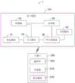
图1为本发明的门禁系统的较佳实施例的功能模块示意图。FIG. 1 is a schematic diagram of functional modules of a preferred embodiment of the access control system of the present invention.
主要元件符号说明Description of main component symbols
门禁系统 1Access Control System 1
读卡装置 100
供电模块 10
开关模块 20
RFID读取器 30
天线模块 40
传感器 50
处理器 60
门禁卡 200
存储器 220
驱动模块 240drive
磁性件 260
如下具体实施方式将结合上述附图进一步说明本发明。The following specific embodiments will further illustrate the present invention in conjunction with the above drawings.
具体实施方式Detailed ways
下面将结合本发明实施例中的附图,对本发明实施例中的技术方案进行清楚、完整地描述,显然,所描述的实施例仅仅是本发明一部分实施例,而不是全部的实施例。基于本发明中的实施例,本领域普通技术人员在没有做出创造性劳动前提下所获得的所有其他实施例,都属于本发明保护的范围。The technical solutions in the embodiments of the present invention will be clearly and completely described below with reference to the accompanying drawings in the embodiments of the present invention. Obviously, the described embodiments are only a part of the embodiments of the present invention, but not all of the embodiments. Based on the embodiments of the present invention, all other embodiments obtained by those of ordinary skill in the art without creative efforts shall fall within the protection scope of the present invention.
需要说明的是,当一个组件被称为“电性连接”另一个组件,它可以直接在另一个组件上或者也可以存在居中的组件。当一个组件被认为是“电性连接”另一个组件,它可以是接触连接,例如,可以是导线连接的方式,也可以是非接触式连接,例如,可以是非接触式耦合的方式。It should be noted that when a component is said to be "electrically connected" to another component, it may be directly on the other component or there may also be a central component. When a component is considered to be "electrically connected" to another component, it can be a contact connection, eg, a wire connection, or a contactless connection, eg, a contactless coupling.
除非另有定义,本文所使用的所有的技术和科学术语与属于本发明的技术领域的技术人员通常理解的含义相同。本文中在本发明的说明书中所使用的术语只是为了描述具体的实施例的目的,不是旨在于限制本发明。本文所使用的术语“及/或”包括一个或多个相关的所列项目的任意的和所有的组合。Unless otherwise defined, all technical and scientific terms used herein have the same meaning as commonly understood by one of ordinary skill in the art to which this invention belongs. The terms used herein in the description of the present invention are for the purpose of describing specific embodiments only, and are not intended to limit the present invention. As used herein, the term "and/or" includes any and all combinations of one or more of the associated listed items.
下面结合附图,对本发明的一些实施方式作详细说明。在不冲突的情况下,下述的实施例及实施例中的特征可以相互组合。Some embodiments of the present invention will be described in detail below with reference to the accompanying drawings. The embodiments described below and features in the embodiments may be combined with each other without conflict.
请参阅图1,本发明较佳示例实施方式提供一种门禁系统1,包括一读卡装置100及一门禁卡200。所述门禁卡200具有标识符。本实施例中,所述标识符为无线电射频识别(Radio Frequency Identification,RFID)技术的标识符。所述读卡装置100采用RFID技术藉由发射射频讯号、接收及解调所述门禁卡200中的标识符,并判断此门禁卡200的标识符的合法性及有效性。Referring to FIG. 1 , a preferred exemplary embodiment of the present invention provides an access control system 1 , including a
在至少一示例性的实施例中,所述门禁系统1可为应用于一通道口,所述读卡装置100可安装于所述通道口的门上或墙面上,所述门禁卡200由用户携带,所述读卡装置100用于判断所述门禁卡200的标识符的合法性及有效性,以决定是否开启通道口。In at least one exemplary embodiment, the access control system 1 can be applied to a passageway, the
在至少一示例性的实施例中,所述供电模块10透过所述开关模块20电性连接至所述RFID读取器30。所述RFID读取器30电性连接至所述天线模块40。当所述开关模块20闭合时,所述供电模块10透过所述开关模块20连通至所述RFID读取器30及所述天线模块40,以向所述读卡装置100供电。当所述开关模块20打开时,所述供电模块10与所述RFID读取器30及所述天线模块40断开连接,所述供电模块10停止向所述读卡装置100供电。在至少一示例性的实施例中,所述供电模块10可耦接一交流电源(图未示出),以提供所述读卡装置100运作所需的电力需求。在另一示例性的实施例中,所述供电模块10装设电池或内建超级电容,以提供所述读卡装置100运作所需的电力需求。至少一示例性的实施例中,所述供电模块10可为任一形式的电源输出装置,以稳定地提供所述读卡装置100运作所需的电力需求。In at least one exemplary embodiment, the
在至少一示例性的实施例中,所述开关模块20可为一受控于逻辑电压的开关。当所述开关模块20在低电压保持打开状态;当所述开关模块20接收到一高电压时,切换为闭合状态。In at least one exemplary embodiment, the
在至少一示例性的实施例中,所述RFID读取器30接收到所述供电模块10的供电时,透过所述天线模块40发射射频讯号,以驱动所述门禁卡200发射所述标识符。所述RFID读取器30还透过所述天线模块40接收所述门禁卡200发射的所述标识符,并对所述标识符进行解调。可以理解,所述天线模块40具有一辐射范围,当所述门禁卡200进入所述辐射范围内时,所述天线模块40发射的射频讯号可传达所述门禁卡200,以及可接收到所述门禁卡200发射的所述标识符,也即在所述辐射范围内时,所述读卡装置100可与所述门禁卡200可建立无线通信连接。In at least one exemplary embodiment, when the
在另一示例性的实施例中,所述RFID读取器30可为其他类型的无线标签读取器,所述无线标签读取器透过其他的通讯方式,例如WIFI、蓝牙(BLUETOOTH)等,来读取所述门禁卡200的所述标识符。In another exemplary embodiment, the
在至少一示例性的实施例中,所述传感器50用于侦测磁性物质(如:一磁性件),并藉此传送一侦测讯号。在至少一示例性的实施例中,所述传感器50可以为但不限于为一霍尔传感器(HallSensor),当一磁性物质靠近所述传感器50,所述传感器50侦测到一磁场的变化,即侦测到的磁通量增大,并藉此传送一侦测讯号。在此实施例中,所述侦测讯号为一逻辑高电压讯号。可以理解,所述传感器50具有一侦测范围,当所述磁性物质进入所述侦测范围内时,所述传感器50侦测到磁场的变化。In at least one exemplary embodiment, the
在至少一示例性的实施例中,所述传感器50分别电性连接至所述开关模块20及所述处理器60,并将所述侦测讯号分别传送至所述开关模块20及所述处理器60。In at least one exemplary embodiment, the
在至少一示例性的实施例中,所述处理器60电性连接至所述RFID读取器30,用于判断所述RFID读取器30接收的标识符的合法性及有效性。所述读卡装置100可储存有默认值。在至少一示例性的实施例中,所述处理器60为微控制单元(Microcontroller Unit,MCU),所述处理器60比对所述标识符与所述默认值,当两者匹配时,则判断所述标识符为合法的。可以理解,当所述处理器60判断所述标识符为合法时,即确认所述门禁卡200的身份,以进一步控制通道口的动作,如开启通道口的门。在至少一示例性的实施例中,所述处理器60具有一使能端(图未示),当接收到一逻辑高电压时,所述处理器60被唤醒以进入工作状态。在所述处理器60的使能端未收到逻辑高电压时,可处于休眠状态。In at least one exemplary embodiment, the
所述门禁卡200包括一存储器220、一驱动模块240及一磁性件260。The
所述存储器220储存有所述标识符。在至少一示例性的实施例中,所述标识符是唯一的,标记着所述门禁卡的身份。The
所述驱动模块240用于当接收到所述读卡装置100发射的射频讯号时被驱动,并发射所述标识符至所述读卡装置100。The
所述磁性件260可内置于所述门禁卡200的壳体中。另外,也可露出于所述门禁卡200的壳体外。The
在至少一示例性的实施例中,当所述读卡装置100在静置时,所述开关模块20处于打开状态,所述供电模块10与所述RFID读取器30断开连接,而所述供电模块10不供电。因此,所述读卡装置100达到了节省电能的效果。In at least one exemplary embodiment, when the
在至少一示例性的实施例中,当用户使用所述门禁卡200进行身份验证时,所述门禁卡200靠近所述读卡装置100,所述门禁卡200的磁性件260进入所述读卡装置100的传感器50的侦测范围。所述传感器50侦测到磁场的变化(即磁通量增大),并分别传送一侦测讯号至所述开关模块20及所述处理器60。本实施例中,所述侦测讯号为一逻辑高电压讯号。所述开关模块20接收到所述逻辑高电压讯号,切换为闭合状态,所述供电模块10透过所述开关模块20电性连接至所述RFID读取器30,以供电至所述RFID读取器30工作。所述RFID读取器30透过所述天线模块40发射射频讯号,所述门禁卡200的驱动模块240接收所述射频讯号并被驱动,并发射所述标识符至所述读卡装置100。所述RFID读取器30透过所述天线模块40接收所述门禁卡200发射的所述标识符,并对所述标识符进行解调后传送至所述处理器60。所述处理器60接收到所述逻辑高电压讯号后被唤醒以进入工作状态。所述处理器60比对所述标识符与所述默认值,以判断所述标识符的合法性,从而对所述门禁卡200进行身份认证。In at least one exemplary embodiment, when a user uses the
所述读卡装置100在闲置时,即所述传感器50未侦测到磁场变化时,所述供电模块10不供电,因此而有效地节约了电能。当所述门禁卡200靠近所述读卡装置100时,透过所述传感器50侦测磁场变化以接通所述供电模块10供电,使得所述读卡装置100对门禁卡200进行身份认证。因此,所述读卡装置100暨可保障正常工作,也可有效地节约电能,降低了成本,符合绿色环保的需要。When the
以上实施方式仅用以说明本发明的技术方案而非限制,尽管参照以上较佳实施方式对本发明进行了详细说明,本领域的普通技术人员应当理解,可以对本发明的技术方案进行修改或等同替换都不应脱离本发明技术方案的精神和范围。本领域技术人员还可在本发明精神内做其它变化等用在本发明的设计,只要其不偏离本发明的技术效果均可。这些依据本发明精神所做的变化,都应包含在本发明所要求保护的范围之内。The above embodiments are only used to illustrate the technical solutions of the present invention and not to limit them. Although the present invention has been described in detail with reference to the above preferred embodiments, those of ordinary skill in the art should understand that the technical solutions of the present invention can be modified or equivalently replaced. Neither should depart from the spirit and scope of the technical solutions of the present invention. Those skilled in the art can also make other changes within the spirit of the present invention to be used in the design of the present invention, as long as they do not deviate from the technical effects of the present invention. These changes made according to the spirit of the present invention should all be included within the scope of the claimed protection of the present invention.
Claims (10)
Priority Applications (2)
| Application Number | Priority Date | Filing Date | Title |
|---|---|---|---|
| CN201910221609.4ACN111798604A (en) | 2019-03-21 | 2019-03-21 | Card reader and access control system |
| TW109106801ATW202037355A (en) | 2019-03-21 | 2020-03-02 | Display contrl system and method |
Applications Claiming Priority (1)
| Application Number | Priority Date | Filing Date | Title |
|---|---|---|---|
| CN201910221609.4ACN111798604A (en) | 2019-03-21 | 2019-03-21 | Card reader and access control system |
Publications (1)
| Publication Number | Publication Date |
|---|---|
| CN111798604Atrue CN111798604A (en) | 2020-10-20 |
Family
ID=72804809
Family Applications (1)
| Application Number | Title | Priority Date | Filing Date |
|---|---|---|---|
| CN201910221609.4APendingCN111798604A (en) | 2019-03-21 | 2019-03-21 | Card reader and access control system |
Country Status (2)
| Country | Link |
|---|---|
| CN (1) | CN111798604A (en) |
| TW (1) | TW202037355A (en) |
Citations (12)
| Publication number | Priority date | Publication date | Assignee | Title |
|---|---|---|---|---|
| CN102279282A (en)* | 2011-07-04 | 2011-12-14 | 江苏大学 | Wind speed sensor used for detecting foreign fiber in cotton and detection method thereof |
| CN202523081U (en)* | 2011-12-29 | 2012-11-07 | 海能达通信股份有限公司 | RFID system, night patrol system, night patrol machine and label device |
| CN102945381A (en)* | 2012-10-15 | 2013-02-27 | 北京物资学院 | Sensor device and work method of sensor device |
| CN103376880A (en)* | 2012-04-27 | 2013-10-30 | 瑟克公司 | Battery powered energy-saving system comprising touch sensor and RFID tag reader |
| CN104850812A (en)* | 2015-05-29 | 2015-08-19 | 成都四方信息技术有限公司 | Energy-saving card reading circuit, method and system of radio frequency card |
| CN105059245A (en)* | 2015-08-05 | 2015-11-18 | 合肥格易集成电路有限公司 | Vehicle control method and device |
| US20160307007A1 (en)* | 2015-04-15 | 2016-10-20 | Motorola Mobility Llc | Utilizing a radio frequency identification tag to assess the battery level of a peripheral device |
| CN106096471A (en)* | 2016-08-09 | 2016-11-09 | 安徽汉威电子有限公司 | A kind of low power consumption, RF card is without switch inspection card system |
| CN106522686A (en)* | 2016-12-30 | 2017-03-22 | 卓捷创芯科技(深圳)有限公司 | Intelligent door lock based on passive radio frequency identification tag |
| CN106710035A (en)* | 2016-10-26 | 2017-05-24 | 乐视控股(北京)有限公司 | Unlocking and locking methods and equipment |
| CN206283482U (en)* | 2016-12-16 | 2017-06-27 | 鞍钢集团矿业有限公司 | A kind of contact proximity switch based on Hall sensor |
| CN108377146A (en)* | 2018-04-16 | 2018-08-07 | 歌尔科技有限公司 | A kind of Hall detection circuit and intelligent wearable device |
- 2019
- 2019-03-21CNCN201910221609.4Apatent/CN111798604A/enactivePending
- 2020
- 2020-03-02TWTW109106801Apatent/TW202037355A/enunknown
Patent Citations (12)
| Publication number | Priority date | Publication date | Assignee | Title |
|---|---|---|---|---|
| CN102279282A (en)* | 2011-07-04 | 2011-12-14 | 江苏大学 | Wind speed sensor used for detecting foreign fiber in cotton and detection method thereof |
| CN202523081U (en)* | 2011-12-29 | 2012-11-07 | 海能达通信股份有限公司 | RFID system, night patrol system, night patrol machine and label device |
| CN103376880A (en)* | 2012-04-27 | 2013-10-30 | 瑟克公司 | Battery powered energy-saving system comprising touch sensor and RFID tag reader |
| CN102945381A (en)* | 2012-10-15 | 2013-02-27 | 北京物资学院 | Sensor device and work method of sensor device |
| US20160307007A1 (en)* | 2015-04-15 | 2016-10-20 | Motorola Mobility Llc | Utilizing a radio frequency identification tag to assess the battery level of a peripheral device |
| CN104850812A (en)* | 2015-05-29 | 2015-08-19 | 成都四方信息技术有限公司 | Energy-saving card reading circuit, method and system of radio frequency card |
| CN105059245A (en)* | 2015-08-05 | 2015-11-18 | 合肥格易集成电路有限公司 | Vehicle control method and device |
| CN106096471A (en)* | 2016-08-09 | 2016-11-09 | 安徽汉威电子有限公司 | A kind of low power consumption, RF card is without switch inspection card system |
| CN106710035A (en)* | 2016-10-26 | 2017-05-24 | 乐视控股(北京)有限公司 | Unlocking and locking methods and equipment |
| CN206283482U (en)* | 2016-12-16 | 2017-06-27 | 鞍钢集团矿业有限公司 | A kind of contact proximity switch based on Hall sensor |
| CN106522686A (en)* | 2016-12-30 | 2017-03-22 | 卓捷创芯科技(深圳)有限公司 | Intelligent door lock based on passive radio frequency identification tag |
| CN108377146A (en)* | 2018-04-16 | 2018-08-07 | 歌尔科技有限公司 | A kind of Hall detection circuit and intelligent wearable device |
Also Published As
| Publication number | Publication date |
|---|---|
| TW202037355A (en) | 2020-10-16 |
Similar Documents
| Publication | Publication Date | Title |
|---|---|---|
| CN102768781B (en) | NFC (Near Field Communication) mobile phone electronic lock control system and NFC mobile phone electronic lock control device | |
| KR100869888B1 (en) | Household entrance access control device and household entrance entrance access control system including the same | |
| WO2010060326A1 (en) | Radio frequency sim card, radio frequency card reader and magnetic induction control method for radio frequency communication | |
| JPH09212603A (en) | Battery built-in type wireless id device and id interrogator | |
| CN203673491U (en) | Radio frequency card detecting apparatus | |
| CN203552291U (en) | Active non-contact intelligent card | |
| CN206224632U (en) | It is a kind of can multimode open the door intelligent access control system | |
| CN113920621B (en) | NFC-based access control of Internet of things and setting method thereof | |
| CN206972122U (en) | A kind of smart home timber | |
| CN109469412A (en) | A smart door lock with wireless power supply face recognition | |
| CN207676392U (en) | Access control equipment | |
| CN207704504U (en) | Access control equipment | |
| CN207882995U (en) | Access control equipment | |
| CN111798604A (en) | Card reader and access control system | |
| TW202036484A (en) | Card reader device and access control system | |
| CN203300012U (en) | RFID-based electronic housekeeper system | |
| CA2925979A1 (en) | Electronic locks with low-cost and low-power consumption smart rfid tags | |
| CN106548540A (en) | A kind of NFC intelligent door locks | |
| CN204904487U (en) | Domestic illegal monitoring alarm system that swarms into based on RFID technique | |
| CN211313753U (en) | IC card type caravan door lock capable of being remotely controlled | |
| CN104850812B (en) | A kind of energy-conservation card reading circuit of radio-frequency card, method and system | |
| KR20050081503A (en) | Radio frequency identity tag for reducing the power consumption | |
| CN204117179U (en) | Band is stable triggers output function NFC label and electronic equipment | |
| CN206236096U (en) | A kind of intelligent card read/write device of power adjustable | |
| CN205028319U (en) | Card system is read to bluetooth ID card based on intelligent Mobile Terminal |
Legal Events
| Date | Code | Title | Description |
|---|---|---|---|
| PB01 | Publication | ||
| PB01 | Publication | ||
| SE01 | Entry into force of request for substantive examination | ||
| SE01 | Entry into force of request for substantive examination | ||
| WD01 | Invention patent application deemed withdrawn after publication | Application publication date:20201020 | |
| WD01 | Invention patent application deemed withdrawn after publication |