CN111789649A - Closing drive mechanism and medical stapler including the same - Google Patents
Closing drive mechanism and medical stapler including the sameDownload PDFInfo
- Publication number
- CN111789649A CN111789649ACN201910281879.4ACN201910281879ACN111789649ACN 111789649 ACN111789649 ACN 111789649ACN 201910281879 ACN201910281879 ACN 201910281879ACN 111789649 ACN111789649 ACN 111789649A
- Authority
- CN
- China
- Prior art keywords
- sliding block
- closing drive
- stapler
- drive mechanism
- groove
- Prior art date
- Legal status (The legal status is an assumption and is not a legal conclusion. Google has not performed a legal analysis and makes no representation as to the accuracy of the status listed.)
- Granted
Links
Images


Classifications
- A—HUMAN NECESSITIES
- A61—MEDICAL OR VETERINARY SCIENCE; HYGIENE
- A61B—DIAGNOSIS; SURGERY; IDENTIFICATION
- A61B17/00—Surgical instruments, devices or methods
- A61B17/11—Surgical instruments, devices or methods for performing anastomosis; Buttons for anastomosis
- A61B17/1114—Surgical instruments, devices or methods for performing anastomosis; Buttons for anastomosis of the digestive tract, e.g. bowels or oesophagus
- A—HUMAN NECESSITIES
- A61—MEDICAL OR VETERINARY SCIENCE; HYGIENE
- A61B—DIAGNOSIS; SURGERY; IDENTIFICATION
- A61B17/00—Surgical instruments, devices or methods
- A61B17/068—Surgical staplers, e.g. containing multiple staples or clamps
- A61B17/072—Surgical staplers, e.g. containing multiple staples or clamps for applying a row of staples in a single action, e.g. the staples being applied simultaneously
- A61B17/07207—Surgical staplers, e.g. containing multiple staples or clamps for applying a row of staples in a single action, e.g. the staples being applied simultaneously the staples being applied sequentially
- A—HUMAN NECESSITIES
- A61—MEDICAL OR VETERINARY SCIENCE; HYGIENE
- A61B—DIAGNOSIS; SURGERY; IDENTIFICATION
- A61B17/00—Surgical instruments, devices or methods
- A61B17/11—Surgical instruments, devices or methods for performing anastomosis; Buttons for anastomosis
- A61B17/115—Staplers for performing anastomosis, e.g. in a single operation
- A61B17/1155—Circular staplers comprising a plurality of staples
- A—HUMAN NECESSITIES
- A61—MEDICAL OR VETERINARY SCIENCE; HYGIENE
- A61B—DIAGNOSIS; SURGERY; IDENTIFICATION
- A61B17/00—Surgical instruments, devices or methods
- A61B17/11—Surgical instruments, devices or methods for performing anastomosis; Buttons for anastomosis
- A61B2017/1132—End-to-end connections
- A—HUMAN NECESSITIES
- A61—MEDICAL OR VETERINARY SCIENCE; HYGIENE
- A61B—DIAGNOSIS; SURGERY; IDENTIFICATION
- A61B17/00—Surgical instruments, devices or methods
- A61B17/11—Surgical instruments, devices or methods for performing anastomosis; Buttons for anastomosis
- A61B2017/1135—End-to-side connections, e.g. T- or Y-connections
Landscapes
- Health & Medical Sciences (AREA)
- Life Sciences & Earth Sciences (AREA)
- Surgery (AREA)
- Heart & Thoracic Surgery (AREA)
- Engineering & Computer Science (AREA)
- Biomedical Technology (AREA)
- Nuclear Medicine, Radiotherapy & Molecular Imaging (AREA)
- Medical Informatics (AREA)
- Molecular Biology (AREA)
- Animal Behavior & Ethology (AREA)
- General Health & Medical Sciences (AREA)
- Public Health (AREA)
- Veterinary Medicine (AREA)
- Physiology (AREA)
- Portable Nailing Machines And Staplers (AREA)
Abstract
Description
Translated fromChinese技术领域technical field
本发明涉及医疗器械技术领域,具体涉及一种闭合驱动机构及包括其的医用吻合器。The invention relates to the technical field of medical devices, in particular to a closing drive mechanism and a medical stapler including the same.
背景技术Background technique
消化道疾病是人类高发的疾病之一,在治疗过程中,常使用医用吻合器代替医生的手工操作对消化道等生理组织进行吻合。医用吻合器是一种常见的外科手术器械,大多采用轴向内装订方式,在手术时对食管、胃、肠道等生理组织形成端对端的、或者端对侧的吻合,吻合时两段组织内敛收容于医用吻合器内,击发完成后在组织上形成圆形吻合口,重建了人体通道。Digestive tract disease is one of the most common diseases in human beings. In the course of treatment, medical staplers are often used to perform anastomosis on physiological tissues such as the digestive tract instead of the manual operation of doctors. Medical stapler is a common surgical instrument, most of which use axial inward binding. During surgery, end-to-end or end-to-side anastomosis is formed on physiological tissues such as esophagus, stomach, and intestinal tract. It is restrained and accommodated in the medical stapler, and after the firing is completed, a circular anastomosis is formed on the tissue, and the human body passage is reconstructed.
现有技术中,医用吻合器包括医用吻合器本体、活动连接所述医用吻合器本体的操作把手以及与所述本体配合的钉头部。所述钉头部包括相对设置的钉仓和钉砧。在手术时,首先握持活动把手,通过闭合驱动机构拉动钉头部的闭合拉片向吻合器的近端侧运动,从而将钉仓和钉砧组件闭合后,再次握持操作把手,可以推动吻合钉向组织运动,通过钉仓中的吻合钉在钉砧组件处的成型,将组织吻合。在本发明中,远端侧和近端侧是相对于操作者来说的,距离操作者较近的一端为近端侧,距离操作者较远的一端,即更靠近手术位置的一端为远端侧。In the prior art, a medical stapler includes a medical stapler body, an operating handle movably connected to the medical stapler body, and a nail head matched with the body. The staple head includes a staple cartridge and a staple anvil arranged oppositely. During the operation, first hold the movable handle, and pull the closing pull tab of the staple head to move toward the proximal side of the stapler through the closing drive mechanism, so as to close the staple cartridge and the staple anvil assembly, and then hold the operating handle again to push The staples move toward the tissue, and the staples in the staple cartridge are formed at the anvil assembly to staple the tissue. In the present invention, the distal side and the proximal side are relative to the operator, the end that is closer to the operator is the proximal side, and the end that is farther from the operator, that is, the end that is closer to the surgical site, is the distal end end side.
现有的闭合驱动机构中,结构较为复杂,并且在击发吻合器的过程中,闭合拉片可能会有向吻合器远端侧方向的位移,而影响钉仓和钉砧之间的闭合效果,对手术效果有不利影响。In the existing closing drive mechanism, the structure is relatively complex, and in the process of firing the stapler, the closing pull tab may be displaced toward the distal side of the stapler, which affects the closing effect between the staple cartridge and the staple anvil. adversely affect the surgical outcome.
发明内容SUMMARY OF THE INVENTION
针对现有技术中的问题,本发明的目的在于提供一种闭合驱动机构及包括其的医用吻合器,通过保持件对钉头部闭合时闭合驱动机构的位置进行限定,避免吻合器击发时闭合拉片向吻合器的远端侧方向运动。In view of the problems in the prior art, the purpose of the present invention is to provide a closing drive mechanism and a medical stapler including the same, the position of the closing drive mechanism when the nail head is closed is limited by the holder, so as to avoid closing when the stapler is fired The pull tab moves toward the distal side of the stapler.
本发明实施例提供一种闭合驱动机构,用于医用吻合器,所述闭合驱动机构包括活动把手、第一滑块、保持件、转向组件和闭合驱动件,所述转向组件连接于所述第一滑块和所述闭合驱动件之间,所述第一滑块上设置有凹槽,初始状态下,所述第一滑块位于所述保持件的近端侧;握持所述活动把手时,所述活动把手推动所述第一滑块向吻合器的远端侧方向运动,所述转向组件将所述第一滑块向所述吻合器的远端侧方向的运动转换为所述闭合驱动件向所述吻合器的近端侧方向的运动,所述保持件至少部分进入所述第一滑块的凹槽中,以阻碍所述第一滑块朝向所述吻合器的近端侧的运动。An embodiment of the present invention provides a closing drive mechanism for a medical stapler. The closing drive mechanism includes a movable handle, a first slider, a holder, a steering assembly, and a closing drive. The steering assembly is connected to the first slider. Between a sliding block and the closing drive member, a groove is provided on the first sliding block. In the initial state, the first sliding block is located at the proximal end side of the holding member; hold the movable handle When the movable handle pushes the first sliding block to move toward the distal side of the stapler, the steering assembly converts the movement of the first sliding block toward the distal side of the stapler into the The movement of the closing drive in the proximal direction of the stapler, the retainer at least partially enters the groove of the first slider to block the first slider toward the proximal end of the stapler side movement.
可选地,所述转向组件包括转向支撑梁和拉绳,所述转向支撑梁位于所述第一滑块的近端侧,所述拉绳套设于所述转向支撑梁的外部,且所述拉绳连接于所述第一滑块和所述闭合驱动件之间。Optionally, the steering assembly includes a steering support beam and a pull rope, the steering support beam is located on the proximal end side of the first slider, the pull rope is sleeved on the outside of the steering support beam, and the The pulling rope is connected between the first sliding block and the closing drive member.
可选地,所述转向组件包括转向支撑梁设有滑轮,所述拉绳设于所述滑轮的外表面。Optionally, the steering assembly includes a steering support beam provided with a pulley, and the pulling rope is provided on the outer surface of the pulley.
可选地,所述医用吻合器包括钉头部和用于闭合所述钉头部的闭合拉片,所述闭合驱动件套设于所述闭合拉片的外部,且所述闭合驱动件与所述闭合拉片轴向固定。Optionally, the medical stapler includes a staple head and a closing pull tab for closing the staple head, the closing driving member is sleeved on the outside of the closing pulling tab, and the closing driving member is connected with the closing pull tab. The closure tab is axially fixed.
可选地,所述闭合拉片的外部还套设有一套管,所述闭合驱动件套设于所述套管的外部,所述套管的侧面开设有沿所述吻合器的轴向方向延伸的行程槽,所述闭合驱动件中设置有连接销,所述连接销插入所述行程槽中,且所述连接销可沿所述行程槽的延伸方向运动。Optionally, a sleeve is sleeved on the outside of the closing pull-tab, the closing driver is sleeved on the outside of the sleeve, and the side of the sleeve is provided with a sleeve along the axial direction of the stapler. An extended stroke slot, the closing drive member is provided with a connecting pin, the connecting pin is inserted into the stroke slot, and the connecting pin can move along the extending direction of the stroke slot.
可选地,所述闭合驱动件的近端侧设置有一偏置件,所述偏置件给所述闭合驱动件一朝向所述吻合器的远端侧方向的偏置力。Optionally, a biasing member is provided on the proximal end side of the closing driver, and the biasing member gives the closing driver a biasing force toward the distal side of the stapler.
可选地,所述活动把手连接至一连杆,握持所述活动把手时,所述连杆的远端侧推动所述第一滑块向所述吻合器的远端侧方向运动。Optionally, the movable handle is connected to a link, and when the movable handle is held, the distal end of the link pushes the first slider to move toward the distal end of the stapler.
可选地,所述闭合驱动机构还包括致动杆,握持所述活动把手时,所述活动把手推动所述致动杆向所述吻合器的远端侧方向运动,所述致动杆向下压迫所述保持件,以使得所述保持件至少部分进入所述第一滑块的凹槽。Optionally, the closing drive mechanism further includes an actuating rod, when the movable handle is held, the movable handle pushes the actuating rod to move in the direction of the distal end of the stapler, and the actuating rod The retainer is pressed downward so that the retainer at least partially enters the groove of the first slider.
可选地,所述致动杆的远端侧设有击发件,所述击发件向所述吻合器的远端方向运动时,向下压迫所述保持件,以使得所述保持件至少部分进入所述第一滑块的凹槽。Optionally, a firing member is provided on the distal side of the actuating rod, and when the firing member moves toward the distal end of the stapler, the holding member is pressed downward, so that the holding member is at least partially into the groove of the first slider.
可选地,所述保持件包括第二滑块,所述第二滑块的一侧设置有凸台,握持所述活动把手时,所述凸台进入所述第一滑块的凹槽中。Optionally, the holder includes a second sliding block, a boss is provided on one side of the second sliding block, and when the movable handle is held, the boss enters the groove of the first sliding block middle.
可选地,所述保持件还包括第三滑块,所述第三滑块开设有容纳所述第二滑块的容置槽。Optionally, the holder further includes a third sliding block, and the third sliding block is provided with an accommodating groove for accommodating the second sliding block.
可选地,所述第三滑块的近端侧设有第五斜面,所述击发件的远端侧设有斜台面,所述第五斜面与所述斜台面互为导向。Optionally, the proximal end side of the third sliding block is provided with a fifth inclined surface, the distal end side of the firing member is provided with an inclined table surface, and the fifth inclined surface and the inclined table surface are mutually guided.
可选地,所述容置槽中设置有第一偏置件,所述第一偏置件给所述第二滑块一朝向下方的偏置力。Optionally, a first biasing member is provided in the accommodating groove, and the first biasing member gives the second slider a downward biasing force.
可选地,所述第三滑块的下方设置有第二偏置件,所述第二偏置件给所述第三滑块一朝向上方的偏置力。Optionally, a second biasing member is provided below the third sliding block, and the second biasing member gives the third sliding block an upward biasing force.
可选地,所述致动杆的一侧设置有凸缘,握持所述活动把手时,所述凸缘朝向所述吻合器的远端侧方向运动至与所述第三滑块的顶面接触,并压迫所述第三滑块带动所述第二滑块向下运动。Optionally, a flange is provided on one side of the actuating rod, and when the movable handle is held, the flange moves toward the distal end of the stapler to the top of the third sliding block. surface contact, and press the third sliding block to drive the second sliding block to move downward.
可选地,在所述吻合器的近端侧面视图中,所述凸缘和所述第二滑块的凸台分别位于所述致动杆的两侧。Optionally, in the proximal side view of the stapler, the flange and the bosses of the second slider are located on both sides of the actuating rod, respectively.
可选地,所述第一滑块的远端侧面为第一斜面,所述第一斜面从其远端侧向近端侧向上倾斜,所述凸台的近端侧面为与所述第一斜面相配合的第二斜面。Optionally, the distal side surface of the first slider is a first inclined surface, and the first inclined surface is inclined upward from its distal end side to the proximal end side, and the proximal end side surface of the boss is the same as the first inclined surface. A second bevel that matches the bevel.
可选地,所述凹槽的近端侧面为与所述第二斜面配合的第三斜面,所述凹槽的远端侧面和所述凸台的远端侧面均为垂直面。Optionally, the proximal side surface of the groove is a third inclined surface matched with the second inclined surface, and the distal side surface of the groove and the distal side surface of the boss are both vertical surfaces.
可选地,所述保持件包括一弹片,所述弹片包括固定端、按压部和活动端,所述固定端固定于所述吻合器,所述致动杆向下压迫所述按压部时,所述活动端进入所述第一滑块的凹槽中。Optionally, the holder includes an elastic piece, the elastic piece includes a fixed end, a pressing portion and a movable end, the fixed end is fixed to the stapler, and when the actuating rod presses the pressing portion downward, The movable end enters into the groove of the first slider.
可选地,所述弹片的固定端位于所述活动端的远端侧,所述活动端向下方并向所述吻合器的远端侧方向弯折而形成与所述第一滑块的凹槽配合的配合部。Optionally, the fixed end of the elastic piece is located on the distal side of the movable end, and the movable end is bent downward and toward the distal side of the stapler to form a groove with the first slider. mating part.
可选地,所述第一滑块的远端侧面为第一斜面,所述第一斜面从其远端侧向近端侧向上倾斜,所述配合部的近端侧面为与所述第一斜面相配合的第四斜面。Optionally, the distal side surface of the first slider is a first inclined surface, the first inclined surface is inclined upward from the distal end side to the proximal end side thereof, and the proximal end side surface of the matching portion is the same as the first inclined surface. The fourth bevel that matches the bevel.
可选地,所述凹槽的近端侧面为与所述第四斜面配合的第三斜面,所述凹槽的远端侧面为垂直面,所述弹片的活动端形成有与所述凹槽的远端侧面配合的垂直面。Optionally, the proximal side of the groove is a third inclined surface that cooperates with the fourth inclined surface, the distal side of the groove is a vertical surface, and the movable end of the elastic piece is formed with the groove. The distal side of the mate mates with the vertical plane.
本发明实施例还提供一种医用吻合器,包括任一项所述的闭合驱动机构。An embodiment of the present invention further provides a medical stapler, including any one of the closing drive mechanisms.
本发明所提供的闭合驱动机构及包括其的医用吻合器具有如下优点:The closing drive mechanism provided by the present invention and the medical stapler including the same have the following advantages:
本发明提供了一种用于医用吻合器的闭合驱动机构,通过保持件对钉头部闭合时闭合驱动机构的位置进行限定,避免吻合器击发时闭合拉片向吻合器的远端侧方向运动,从而保证吻合器击发过程中钉头部闭合的稳定性,提升手术效果。The invention provides a closing drive mechanism for a medical stapler. The position of the closing drive mechanism when the nail head is closed is limited by a holder, so as to prevent the closing pull tab from moving to the distal side of the stapler when the stapler is fired. , so as to ensure the stability of the closure of the nail head during the firing process of the stapler and improve the surgical effect.
附图说明Description of drawings
通过阅读参照以下附图对非限制性实施例所作的详细描述,本发明的其它特征、目的和优点将会变得更明显。Other features, objects and advantages of the present invention will become more apparent upon reading the detailed description of non-limiting embodiments with reference to the following drawings.
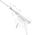
图1是本发明第一实施例的闭合驱动机构与壳体配合的示意图;FIG. 1 is a schematic diagram of the cooperation between the closing drive mechanism and the casing according to the first embodiment of the present invention;
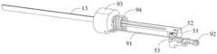
图2是本发明第一实施例的闭合驱动机构与吻合器其他部件配合的结构示意图;2 is a schematic structural diagram of the cooperation between the closing drive mechanism and other components of the stapler according to the first embodiment of the present invention;
图3是本发明第一实施例的闭合驱动机构与吻合器其他部件配合的立体图;FIG. 3 is a perspective view of the first embodiment of the present invention, where the closing drive mechanism cooperates with other components of the stapler;
图4是本发明第一实施例的闭合驱动机构的结构示意图;4 is a schematic structural diagram of the closing drive mechanism according to the first embodiment of the present invention;
图5是本发明第一实施例的示出闭合驱动机构远端侧面的示意图;Figure 5 is a schematic diagram showing the distal side of the closing drive mechanism according to the first embodiment of the present invention;
图6是本发明第一实施例的第一滑块和保持件配合的示意图;FIG. 6 is a schematic diagram of the cooperation of the first slider and the holder according to the first embodiment of the present invention;
图7是本发明第一实施例的保持件的结构示意图;FIG. 7 is a schematic structural diagram of the holder according to the first embodiment of the present invention;
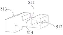
图8是本发明第一实施例的第一滑块的结构示意图;FIG. 8 is a schematic structural diagram of a first slider according to the first embodiment of the present invention;
图9是本发明第一实施例的致动杆的后视图;Figure 9 is a rear view of the actuating lever of the first embodiment of the present invention;
图10是本发明第二实施例的闭合驱动机构与壳体配合的示意图;10 is a schematic view of the second embodiment of the present invention, the closing drive mechanism and the housing cooperate;
图11是本发明第二实施例的闭合驱动机构与吻合器其他部件配合的立体图;11 is a perspective view of the second embodiment of the present invention, the closing drive mechanism cooperates with other components of the stapler;
图12是本发明第二实施例的闭合驱动机构的结构示意图;12 is a schematic structural diagram of a closing drive mechanism according to a second embodiment of the present invention;
图13是本发明第二实施例的保持件与第一滑块配合的示意图。FIG. 13 is a schematic diagram of the second embodiment of the present invention in which the holder is matched with the first slider.
附图标记:Reference number:
1 吻合器本体 61 第一压簧1
11 固定把手 62 第二压簧11
12 套管 7 弹片12
121 行程槽 71 固定端121
13 拉片 72 按压部13
2 壳体 73 拉绳穿过槽2
3 活动把手 74 第四斜面3
31 卡爪 75 活动端31
4 连杆 76 第六斜面4
51 第一滑块 8 致动杆51
511 第一凹槽 81 推进齿511
512 第二凹槽 82 齿条512
513 第一斜面 83 击发件513
514 第三斜面 831 斜台面514
52 第二滑块 84 凸缘52
521 凸台 841 凸缘斜面521
522 第二斜面 91 拉绳522
53 第三滑块 92 滑轮53
531 容置槽 93 闭合驱动件531
532 顶面 94 第三压簧532
535 第五斜面 95 连接销535
具体实施方式Detailed ways
现在将参考附图更全面地描述示例实施方式。然而,示例实施方式能够以多种形式实施,且不应被理解为限于在此阐述的实施方式;相反,提供这些实施方式使得本发明将全面和完整,并将示例实施方式的构思全面地传达给本领域的技术人员。在图中相同的附图标记表示相同或类似的结构,因而将省略对它们的重复描述。Example embodiments will now be described more fully with reference to the accompanying drawings. Example embodiments, however, can be embodied in various forms and should not be construed as limited to the embodiments set forth herein; rather, these embodiments are provided so that this disclosure will be thorough and complete, and will fully convey the concept of example embodiments to those skilled in the art. The same reference numerals in the drawings denote the same or similar structures, and thus their repeated descriptions will be omitted.
为了解决现有技术中的技术问题,本发明提供了一种用于医用吻合器的闭合驱动机构以及包括该钉仓的医用吻合器。所述吻合器包括钉头部和吻合器本体,所述吻合器本体中设置有用于闭合所述钉头部的闭合拉片。所述闭合驱动机构用于医用吻合器,所述闭合驱动机构包括活动把手、第一滑块、保持件、转向组件和闭合驱动件,所述转向组件连接于所述第一滑块和所述闭合驱动件之间,所述第一滑块上设置有凹槽,初始状态下,所述第一滑块位于所述保持件的近端侧;握持所述活动把手时,所述活动把手推动所述第一滑块向吻合器的远端侧方向运动,所述转向组件将所述第一滑块向所述吻合器的远端侧方向的运动转换为所述闭合驱动件向所述吻合器的近端侧方向的运动,闭合驱动件拉动所述闭合拉片向吻合器的近端侧方向运动,以使得所述钉头部闭合,此时所述保持件至少部分进入所述第一滑块的凹槽中,以阻碍所述第一滑块朝向所述吻合器的近端侧的运动。当术者检查好待吻合的组织,确认吻合器可以击发后,切换到吻合器的可击发状态,再次握持所述活动把手时,可以击发吻合器,并且由于第一滑块不会发生向吻合器近端侧的运动,闭合驱动件也不会给闭合拉片以向吻合器远端侧的驱动力,可以保持钉头部的闭合。In order to solve the technical problems in the prior art, the present invention provides a closing drive mechanism for a medical stapler and a medical stapler including the staple cartridge. The stapler includes a staple head and a stapler body, and the stapler body is provided with a closing tab for closing the staple head. The closing drive mechanism is used for a medical stapler, and the closing drive mechanism includes a movable handle, a first sliding block, a holding member, a steering assembly and a closing driving member, and the steering assembly is connected to the first sliding block and the closing drive member. Between the closing drive members, a groove is provided on the first sliding block. In the initial state, the first sliding block is located at the proximal end side of the holding member; when the movable handle is held, the movable handle Pushing the first slider to move towards the distal side of the stapler, the steering assembly converts the movement of the first slider towards the distal side of the stapler into a movement of the closing drive member towards the distal side of the stapler When the stapler moves in the proximal direction, the closing driver pulls the closing pull tab to move toward the proximal end of the stapler, so that the staple head is closed, and the retainer is at least partially inserted into the first. a groove of the slider to block the movement of the first slider toward the proximal end side of the stapler. When the operator checks the tissue to be anastomosed and confirms that the stapler can be fired, the surgeon switches to the fireable state of the stapler, and when holding the movable handle again, the stapler can be fired. With the movement of the proximal end of the stapler, the closing driver will not give the closing puller a driving force toward the distal end of the stapler, so that the staple head can be kept closed.
下面结合图1~13介绍本发明一实施例的闭合驱动机构和医用吻合器的结构。其中图1~9中示出了本发明第一实施例的闭合驱动机构和医用吻合器的结构,图10~13示出了本发明第二实施例的闭合驱动机构和医用吻合器的结构。其中,第一实施例和第二实施例的保持件结构不同。The following describes the structure of a closing drive mechanism and a medical stapler according to an embodiment of the present invention with reference to FIGS. 1 to 13 . 1 to 9 show the structures of the closing drive mechanism and the medical stapler according to the first embodiment of the present invention, and FIGS. 10 to 13 show the structures of the closing drive mechanism and the medical stapler according to the second embodiment of the present invention. Among them, the structure of the holder of the first embodiment and the second embodiment is different.
如图1~9所示,在本发明第一实施例中,所述吻合器包括吻合器本体1和位于吻合器本体1的远端侧的钉头部(图中未示出),吻合器本体1包括壳体2和固定把手11,吻合器本体1的内部还设置有用于闭合钉头部和打开钉头部的闭合拉片13,闭合拉片13的外部套设有套管12。所述闭合驱动机构包括旋转连接至吻合器本体1的活动把手3、位于所述吻合器本体1内的第一滑块51、保持件、转向组件、击发件83和与所述闭合拉片13相连接的闭合驱动件93,所述转向组件连接于所述第一滑块51和所述闭合驱动件93之间,所述第一滑块51上设置有第一凹槽511。初始状态下,所述第一滑块51位于所述保持件的近端侧;握持所述活动把手3时,所述活动把手3推动所述第一滑块51向吻合器的远端侧方向运动,所述转向组件将所述第一滑块51向所述吻合器的远端侧方向的运动转换为所述闭合驱动件93向所述吻合器的近端侧方向的运动,闭合驱动件93拉动所述闭合拉片13向吻合器的近端侧方向运动,以使得所述钉头部闭合,此时所述保持件至少部分进入所述第一滑块51的第一凹槽511中,以阻碍所述第一滑块51朝向所述吻合器的近端侧的运动。当切换到可击发模式,再次握持所述活动把手3时,可以击发吻合器,并且由于第一滑块51受到保持件的阻碍而不会发生向吻合器近端侧的运动,闭合驱动件93也不会给闭合拉片13以向吻合器远端侧的驱动力,可以保持钉头部的闭合。对于一个部件来说,其外侧指的是远离吻合器的轴心的一侧,其内侧指的是靠近吻合器的轴心的一侧。As shown in Figures 1 to 9, in the first embodiment of the present invention, the stapler includes a
在本发明中,远端侧和近端侧是相对于操作者来说的,其中,远端侧指的是距离操作者较远的一端,近端侧指的是距离操作者较近的一端。例如,在图1的视角中,吻合器本体1的远端侧为图中左边一端,吻合器本体1的右端为图中右边一端。医用吻合器的轴向方向指的是从医用吻合器的近端侧指向远端侧的方向,即图1中套管12的延伸方向。In the present invention, the distal side and the proximal side are relative to the operator, wherein the distal side refers to the end that is farther from the operator, and the proximal side refers to the end that is closer to the operator . For example, in the perspective of FIG. 1 , the distal end of the
在该实施例中,所述转向组件包括转向支撑梁92和拉绳91,所述转向支撑梁92固设于壳体2,在一优选的实施方式中,所述转向支撑梁92设为滑轮92,以减少所述拉绳91运动时的阻力。所述滑轮92位于所述第一滑块51的近端侧,所述拉绳91套设于所述滑轮92的外部,且所述拉绳91连接于所述第一滑块51和所述闭合驱动件93之间。在一优选的实施方式中,所述拉绳91的两端分别设有固定端。第一滑块51的近端侧可以设置有第二凹槽512,所述拉绳91的一固定端可拆卸地安装于第二凹槽512中。所述拉绳91的另一固定端可拆卸地连接于所述闭合驱动件93。通过拉绳91和滑轮92的结构,可以将第一滑块51的运动转化为反向的驱动力传递给闭合驱动件93,使所述闭合驱动件93向近段运动。In this embodiment, the steering assembly includes a
在该实施例中,所述闭合驱动件93为套设于所述闭合拉片13的外部的一个套管,且所述闭合驱动件93与所述闭合拉片13轴向固定,此处轴向固定指的是闭合驱动件93与闭合拉片13之间不存在沿吻合器轴向的相对运动,如果闭合驱动件93沿轴向向吻合器的近端侧或与远端侧运动时,闭合拉片13与闭合驱动件93联动。进一步地,所述闭合驱动件93套设于所述套管12的外部,所述套管12的侧面开设有沿所述吻合器的轴向方向延伸的行程槽121,所述闭合驱动件93中设置有连接销95,所述连接销95插入所述行程槽121中,且所述连接销95可沿所述行程槽121的延伸方向运动。所述行程槽121连通套管12的内侧面和外侧面,并且连接销95为一个通销,闭合驱动件93通过连接销95与闭合拉片13固定连接的同时,通过连接销95在套管12的行程槽12中的运动,为闭合驱动件93的轴向运动提供导向作用。闭合驱动件93与套管12之间通过连接销95周向固定,即闭合驱动件93可以随套管12绕轴心的旋转而旋转。In this embodiment, the closing
所述闭合驱动件93的近端侧设置有一偏置件,所述偏置件给所述闭合驱动件93一朝向所述吻合器的远端侧方向的偏置力。在该实施例中,该偏置件为第三压簧94,在握持活动把手3以闭合钉头部时,闭合驱动件93向吻合器的近端侧运动而压迫第三压簧94,在吻合器击发完成后复位时,第三压簧94的变形恢复力可以推动闭合驱动件93向吻合器的远端侧运动而返回至初始位置,并且可以打开钉头部。A biasing member is provided at the proximal end side of the
在该实施例中,所述活动把手3连接至一连杆4,握持所述活动把手3时,所述连杆4的远端侧推动所述第一滑块51向所述吻合器的远端侧方向运动。In this embodiment, the
如图2所示,所述闭合驱动机构还包括致动杆8,用于击发吻合器。所述致动杆8的远端侧设置有推进齿81,推进齿81的近端侧设置有齿条82,所述致动杆8的远端侧活动连接一击发件83,所述击发件83可相对于所述致动杆8的其他部分进行360°旋转,且所述击发件83套设并固定连接于所述套管12,所述击发件83的远端侧周向设有斜台面831。活动把手3上还有卡爪31。在第一次握持所述活动把手3时,所述活动把手3的卡爪31推动所述致动杆8的推进齿81,使得所述致动杆8向所述吻合器的远端侧方向运动,所述击发件83的斜台面831逐渐靠近并接触所述保持件,并向下压迫所述保持件,以使得所述保持件至少部分进入所述第一滑块51的第一凹槽511。此时,卡爪31位于与齿条82对应的位置,切换至可击发模式,再次握持活动把手3时,卡爪31推动致动杆8的齿条82,使得致动杆8继续向吻合器的远端侧方向运动,致动杆8推动致动杆8的远端侧的击发件83,以击发吻合器。As shown in Figure 2, the closure drive mechanism further includes an
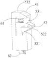
如图4~7所示,在该实施例中,所述保持件包括第二滑块52,所述第二滑块52的一侧设置有凸台521,握持所述活动把手3时,所述击发件向远端侧运动至所述保持件的上方,向下压迫所述保持件,同时,所述第一滑块51向远端侧运动,至少部分所述凸台521的下方,使得所述凸台521进入所述第一滑块51的第一凹槽511中。进一步地,所述保持件还包括第三滑块53,所述第三滑块53开设有容纳所述第二滑块52的容置槽531。所述容置槽531中设置有第一偏置件,所述第一偏置件给所述第二滑块52一朝向下方的偏置力。所述第三滑块53的下方设置有第二偏置件,所述第二偏置件给所述第三滑块53一朝向上方的偏置力。在该实施例中,第一偏置件为第一压簧61,第二偏置件为第二压簧62。具体地,所述第二滑块52靠近所述第一偏置件的一侧设有第一偏置件孔,所述第一偏置件的一端设于所述第一偏置件孔内;所述第三滑块53靠近所述第二偏置件的一端设有第二偏置件孔,所述第二偏置件的一端设于所述第二偏置件孔中,以使得所述第二滑块52及所述第三滑块53在垂直于轴向运动的稳定性。As shown in FIGS. 4 to 7 , in this embodiment, the holder includes a second sliding
如图6和图7所示,为凸台521进入到第一凹槽511中的示意图。在第一次握持活动把手3时,致动杆8和第一滑块51均向吻合器的远端侧方向运动,第一滑块51的第一凹槽511运动至到凸台521的下方。击发杆83压迫第三滑块53向下运动,并压迫第二压簧62,第三滑块53向下运动,在所述第一滑块51向上抬起所述第二滑块52时,所述第一压簧被压缩。第二滑块52的凸台521向下运动进入第一凹槽511中后,在所述第一压簧61的作用下,所述第二滑块52保持在所述第一凹槽511中。在吻合器击发完成后复位时,致动杆8向吻合器近端侧运动返回至初始位置,第三滑块53不再受到击发件83的压迫力,第三滑块53和第二滑块52在第一压簧61和第二压簧62的变形恢复力作用下返回至初始位置,在所述第三压簧的作用下所述闭合驱动件93在所述第三压簧的作用下向远端侧运动,通过所述拉绳91带动所述第一滑块51向吻合器的近端侧运动而返回至初始位置。As shown in FIG. 6 and FIG. 7 , it is a schematic diagram showing that the
在该实施例中,所述致动杆8的一侧还可以进一步设置有凸缘84,握持所述活动把手3时,所述凸缘84朝向所述吻合器的远端侧方向运动至与所述第三滑块53的顶面532接触,并压迫所述第三滑块53向下运动,使得第二滑块52的凸台521进入到第一滑块51的第一凹槽511中。凸缘84压迫第三滑块53和上面描述的击发件83压迫第三滑块53可以作为两种可相互替换的实施方式。在所述吻合器的近端侧面视图中,所述凸缘84和所述第二滑块52的凸台521分别位于所述致动杆8的两侧。即如图3中,从右端面沿轴向方向看过去的视角中,凸缘84位于致动杆8的右侧,凸台521位于致动杆8的左侧。如图9所示,与第三滑块53的第五斜面535相对应地,凸缘84的下端面也设置有与第五斜面535相配合的凸缘斜面841,以与第三滑块53之间相互导向。In this embodiment, a
在该实施例中,所述第一滑块51的远端侧面为第一斜面513,所述第一斜面513从其远端侧向近端侧向上倾斜,所述凸台521的近端侧面为与所述第一斜面513相配合的第二斜面522。第一斜面513和第二斜面522的配合可以更好地引导凸台521进入到第一滑块51中。In this embodiment, the distal side of the
在该实施例中,所述第一凹槽511的近端侧面为与所述第二斜面522配合的第三斜面514,所述第一凹槽511的远端侧面和所述凸台521的远端侧面均为垂直面。即第一凹槽511为与凸台521形状相适应的结构。并且,通过第一凹槽511的远端侧面和所述凸台521的远端侧面这两个垂直面的配合,在凸台521位于第一凹槽511中时,阻挡凸台521从第一滑块51的远端侧脱离。In this embodiment, the proximal side surface of the
如图10~13所示,为本发明第二实施例的闭合驱动机构和吻合器的结构示意图。该实施例与第一实施例的区别在于,所述保持件的结构不同。在该实施例中,所述保持件包括一弹片7,所述弹片7包括固定端71、按压部72和活动端75,所述固定端71固定于所述吻合器,第一次握持活动把手3时,击发件83向吻合器的远端侧方向运动,所述击发件83向下压迫所述按压部72,所述活动端75向下运动进入所述第一滑块51的第一凹槽511中,弹片7发生变形,以阻碍第一滑块51向吻合器的近端侧方向的运动。在吻合器击发完成后,致动杆8向吻合器近端侧方向运动返回至初始位置,而击发件83不再压迫按压部72,在弹片7的变形恢复力的作用下,活动端75向上运动而与第一凹槽511分离,第一滑块51可以向吻合器近端侧运动而返回至初始位置。As shown in Figures 10-13, it is a schematic structural diagram of the closing drive mechanism and the stapler according to the second embodiment of the present invention. The difference between this embodiment and the first embodiment is that the structure of the holder is different. In this embodiment, the holding member includes an
弹片7与拉绳91配合的位置还开设有拉绳穿过槽73,拉绳91可穿过拉绳穿过槽73并在拉绳穿过槽73中轴向运动。The position where the
在该实施例中,所述弹片7的固定端71位于所述活动端75的远端侧,所述活动端75向下方并向所述吻合器的远端侧方向弯折而形成与所述第一滑块51的第一凹槽511配合的配合部。所述第一滑块51的远端侧面为第一斜面513,所述第一斜面513从其远端侧向近端侧向上倾斜,所述配合部的近端侧面为与所述第一斜面513相配合的第四斜面74。第一斜面513和第四斜面74的配合可以更好地引导弹片7的配合部进入到第一凹槽511中。与所述击发件83的斜台面831相对应地,在弹片7的近端侧面也形成有第六斜面76,第六斜面76与击发件83的斜台面831相互导向。该实施例也可以与图9中示出的凸缘84相配合,即凸缘斜面841与第六斜面76相互导向。In this embodiment, the
在该实施例中,所述第一凹槽511的近端侧面为与所述第四斜面74配合的第三斜面,所述第一凹槽511的远端侧面为垂直面,并且所述弹片7的活动端74形成有与所述第一凹槽511的远端侧面配合的垂直面。通过弹片7的活动端74和第一凹槽511的远端侧面这两个垂直面的配合,在活动端74进入到第一凹槽511中时,可以阻碍活动端74从第一凹槽511的远端侧脱离。In this embodiment, the proximal side surface of the
本发明所提供的闭合驱动机构及包括其的医用吻合器具有如下优点:The closing drive mechanism provided by the present invention and the medical stapler including the same have the following advantages:
本发明提供了一种用于医用吻合器的闭合驱动机构,通过保持件对钉头部闭合时闭合驱动机构的位置进行限定,避免吻合器击发时闭合拉片向吻合器的远端侧方向运动,从而保证吻合器击发过程中钉头部闭合的稳定性,提升手术效果。The invention provides a closing drive mechanism for a medical stapler. The position of the closing drive mechanism when the nail head is closed is limited by a holder, so as to prevent the closing pull tab from moving to the distal side of the stapler when the stapler is fired. , so as to ensure the stability of the closure of the nail head during the firing process of the stapler and improve the surgical effect.
以上内容是结合具体的优选实施方式对本发明所作的进一步详细说明,不能认定本发明的具体实施只局限于这些说明。对于本发明所属技术领域的普通技术人员来说,在不脱离本发明构思的前提下,还可以做出若干简单推演或替换,都应当视为属于本发明的保护范围。The above content is a further detailed description of the present invention in conjunction with specific preferred embodiments, and it cannot be considered that the specific implementation of the present invention is limited to these descriptions. For those of ordinary skill in the technical field of the present invention, without departing from the concept of the present invention, some simple deductions or substitutions can be made, which should be regarded as belonging to the protection scope of the present invention.
Claims (23)
Translated fromChinesePriority Applications (1)
| Application Number | Priority Date | Filing Date | Title |
|---|---|---|---|
| CN201910281879.4ACN111789649B (en) | 2019-04-09 | 2019-04-09 | Closed driving mechanism and medical stapler including the same |
Applications Claiming Priority (1)
| Application Number | Priority Date | Filing Date | Title |
|---|---|---|---|
| CN201910281879.4ACN111789649B (en) | 2019-04-09 | 2019-04-09 | Closed driving mechanism and medical stapler including the same |
Publications (2)
| Publication Number | Publication Date |
|---|---|
| CN111789649Atrue CN111789649A (en) | 2020-10-20 |
| CN111789649B CN111789649B (en) | 2025-05-06 |
Family
ID=72805280
Family Applications (1)
| Application Number | Title | Priority Date | Filing Date |
|---|---|---|---|
| CN201910281879.4AActiveCN111789649B (en) | 2019-04-09 | 2019-04-09 | Closed driving mechanism and medical stapler including the same |
Country Status (1)
| Country | Link |
|---|---|
| CN (1) | CN111789649B (en) |
Cited By (5)
| Publication number | Priority date | Publication date | Assignee | Title |
|---|---|---|---|---|
| WO2022148407A1 (en)* | 2021-01-08 | 2022-07-14 | 江苏芸众医疗科技有限公司 | Surgical stapler |
| CN116262059A (en)* | 2021-12-14 | 2023-06-16 | 天臣国际医疗科技股份有限公司 | Closed switching mechanism and medical stapler |
| CN116262055A (en)* | 2021-12-14 | 2023-06-16 | 天臣国际医疗科技股份有限公司 | Closed driving mechanism and medical stapler |
| WO2024017228A1 (en)* | 2022-07-18 | 2024-01-25 | 天臣国际医疗科技股份有限公司 | Closure drive mechanism and medical stapler |
| WO2024188140A1 (en)* | 2023-03-10 | 2024-09-19 | 天臣国际医疗科技股份有限公司 | Surgical instrument |
Citations (11)
| Publication number | Priority date | Publication date | Assignee | Title |
|---|---|---|---|---|
| CA2482726A1 (en)* | 2003-09-29 | 2005-03-29 | Ethicon Endo-Surgery, Inc. | Surgical stapling instrument incorporating a multistroke firing position indicator and retraction mechanism |
| US20050067457A1 (en)* | 2003-09-29 | 2005-03-31 | Shelton Frederick E. | Surgical stapling instrument with multistroke firing incorporating an anti-backup mechanism |
| US20050173490A1 (en)* | 2003-05-20 | 2005-08-11 | Ethicon Endo-Surgery, Inc. | Surgical stapling instrument having an electroactive polymer actuated single lockout mechanism for prevention of firing |
| EP2100561A2 (en)* | 2008-03-12 | 2009-09-16 | Tyco Healthcare Group LP | Ratcheting mechanism for surgical stapling device |
| CN103860230A (en)* | 2014-04-04 | 2014-06-18 | 苏州天臣国际医疗科技有限公司 | Medical stapler |
| CN104688288A (en)* | 2015-03-13 | 2015-06-10 | 苏州天臣国际医疗科技有限公司 | Medical stapler |
| CN204379347U (en)* | 2014-12-30 | 2015-06-10 | 苏州天臣国际医疗科技有限公司 | Nail bin groupware and use the Medical stapler of this nail bin groupware |
| WO2015149715A1 (en)* | 2014-04-04 | 2015-10-08 | 苏州天臣国际医疗科技有限公司 | Medical anastomose device |
| WO2016107447A1 (en)* | 2014-12-30 | 2016-07-07 | 苏州天臣国际医疗科技有限公司 | Medical anastomat |
| WO2017028361A1 (en)* | 2015-08-14 | 2017-02-23 | 上海逸思医疗科技有限公司 | Single-handed-operation surgical instrument and operation method thereof |
| CN209996394U (en)* | 2019-04-09 | 2020-01-31 | 天臣国际医疗科技股份有限公司 | Closing driving mechanism and medical anastomat comprising same |
- 2019
- 2019-04-09CNCN201910281879.4Apatent/CN111789649B/enactiveActive
Patent Citations (11)
| Publication number | Priority date | Publication date | Assignee | Title |
|---|---|---|---|---|
| US20050173490A1 (en)* | 2003-05-20 | 2005-08-11 | Ethicon Endo-Surgery, Inc. | Surgical stapling instrument having an electroactive polymer actuated single lockout mechanism for prevention of firing |
| CA2482726A1 (en)* | 2003-09-29 | 2005-03-29 | Ethicon Endo-Surgery, Inc. | Surgical stapling instrument incorporating a multistroke firing position indicator and retraction mechanism |
| US20050067457A1 (en)* | 2003-09-29 | 2005-03-31 | Shelton Frederick E. | Surgical stapling instrument with multistroke firing incorporating an anti-backup mechanism |
| EP2100561A2 (en)* | 2008-03-12 | 2009-09-16 | Tyco Healthcare Group LP | Ratcheting mechanism for surgical stapling device |
| CN103860230A (en)* | 2014-04-04 | 2014-06-18 | 苏州天臣国际医疗科技有限公司 | Medical stapler |
| WO2015149715A1 (en)* | 2014-04-04 | 2015-10-08 | 苏州天臣国际医疗科技有限公司 | Medical anastomose device |
| CN204379347U (en)* | 2014-12-30 | 2015-06-10 | 苏州天臣国际医疗科技有限公司 | Nail bin groupware and use the Medical stapler of this nail bin groupware |
| WO2016107447A1 (en)* | 2014-12-30 | 2016-07-07 | 苏州天臣国际医疗科技有限公司 | Medical anastomat |
| CN104688288A (en)* | 2015-03-13 | 2015-06-10 | 苏州天臣国际医疗科技有限公司 | Medical stapler |
| WO2017028361A1 (en)* | 2015-08-14 | 2017-02-23 | 上海逸思医疗科技有限公司 | Single-handed-operation surgical instrument and operation method thereof |
| CN209996394U (en)* | 2019-04-09 | 2020-01-31 | 天臣国际医疗科技股份有限公司 | Closing driving mechanism and medical anastomat comprising same |
Cited By (6)
| Publication number | Priority date | Publication date | Assignee | Title |
|---|---|---|---|---|
| WO2022148407A1 (en)* | 2021-01-08 | 2022-07-14 | 江苏芸众医疗科技有限公司 | Surgical stapler |
| US12290262B2 (en) | 2021-01-08 | 2025-05-06 | Jianxin Xue | Stapler |
| CN116262059A (en)* | 2021-12-14 | 2023-06-16 | 天臣国际医疗科技股份有限公司 | Closed switching mechanism and medical stapler |
| CN116262055A (en)* | 2021-12-14 | 2023-06-16 | 天臣国际医疗科技股份有限公司 | Closed driving mechanism and medical stapler |
| WO2024017228A1 (en)* | 2022-07-18 | 2024-01-25 | 天臣国际医疗科技股份有限公司 | Closure drive mechanism and medical stapler |
| WO2024188140A1 (en)* | 2023-03-10 | 2024-09-19 | 天臣国际医疗科技股份有限公司 | Surgical instrument |
Also Published As
| Publication number | Publication date |
|---|---|
| CN111789649B (en) | 2025-05-06 |
Similar Documents
| Publication | Publication Date | Title |
|---|---|---|
| EP3441018A1 (en) | Surgical device with overload mechanism | |
| CN111789649B (en) | Closed driving mechanism and medical stapler including the same | |
| CN209996394U (en) | Closing driving mechanism and medical anastomat comprising same | |
| CN210990510U (en) | Closing drive mechanism and medical stapler including the same | |
| CN210990512U (en) | Closing drive mechanism and medical stapler including the same | |
| CN209644987U (en) | Firing lock and stapler | |
| JP7441842B2 (en) | trigger mechanism and stapler | |
| CN209996389U (en) | Firing mechanism and anastomat | |
| CN112438765B (en) | Closed driving mechanism and medical stapler including the same | |
| US12082816B2 (en) | Closure driving mechanism and surgical stapler | |
| US12256925B2 (en) | Closure driving mechanism and surgical stapler | |
| CN209996393U (en) | Closing drive mechanism and medical stapler including the same | |
| CN214907507U (en) | Firing assemblies and surgical staplers | |
| CN112438764B (en) | Closed driving mechanism and medical stapler including the same | |
| CN211049481U (en) | Anvil and medical stapler including the same | |
| CN111345862B (en) | Firing mechanism and anastomat | |
| RU2792203C1 (en) | Closing drive mechanism and medical stapler containing this closing drive mechanism | |
| CN219461268U (en) | Surgical Stapler | |
| CN209529225U (en) | Firing lock and stapler | |
| CN114680973B (en) | Firing assembly and surgical stapler | |
| CN111317537A (en) | Firing mechanism and anastomat |
Legal Events
| Date | Code | Title | Description |
|---|---|---|---|
| PB01 | Publication | ||
| PB01 | Publication | ||
| SE01 | Entry into force of request for substantive examination | ||
| SE01 | Entry into force of request for substantive examination | ||
| CB02 | Change of applicant information | ||
| CB02 | Change of applicant information | Country or region after:China Address after:No.278 Dongping street, Suzhou Industrial Park, Suzhou City, Jiangsu Province Applicant after:Tianchen International Medical Technology Co.,Ltd. Address before:No.278 Dongping street, Suzhou Industrial Park, Suzhou City, Jiangsu Province Applicant before:TOUCHSTONE INTERNATIONAL MEDICAL SCIENCE Co.,Ltd. Country or region before:China | |
| GR01 | Patent grant | ||
| GR01 | Patent grant |