CN111781251A - A low-concentration gas content measurement device in flue gas - Google Patents
A low-concentration gas content measurement device in flue gasDownload PDFInfo
- Publication number
- CN111781251A CN111781251ACN202010449192.XACN202010449192ACN111781251ACN 111781251 ACN111781251 ACN 111781251ACN 202010449192 ACN202010449192 ACN 202010449192ACN 111781251 ACN111781251 ACN 111781251A
- Authority
- CN
- China
- Prior art keywords
- gas
- desorption
- adsorption
- gas adsorption
- pipe
- Prior art date
- Legal status (The legal status is an assumption and is not a legal conclusion. Google has not performed a legal analysis and makes no representation as to the accuracy of the status listed.)
- Pending
Links
Images


Classifications
- G—PHYSICS
- G01—MEASURING; TESTING
- G01N—INVESTIGATING OR ANALYSING MATERIALS BY DETERMINING THEIR CHEMICAL OR PHYSICAL PROPERTIES
- G01N27/00—Investigating or analysing materials by the use of electric, electrochemical, or magnetic means
- G01N27/26—Investigating or analysing materials by the use of electric, electrochemical, or magnetic means by investigating electrochemical variables; by using electrolysis or electrophoresis
- G—PHYSICS
- G01—MEASURING; TESTING
- G01N—INVESTIGATING OR ANALYSING MATERIALS BY DETERMINING THEIR CHEMICAL OR PHYSICAL PROPERTIES
- G01N1/00—Sampling; Preparing specimens for investigation
- G01N1/28—Preparing specimens for investigation including physical details of (bio-)chemical methods covered elsewhere, e.g. G01N33/50, C12Q
- G01N1/34—Purifying; Cleaning
- G—PHYSICS
- G01—MEASURING; TESTING
- G01N—INVESTIGATING OR ANALYSING MATERIALS BY DETERMINING THEIR CHEMICAL OR PHYSICAL PROPERTIES
- G01N1/00—Sampling; Preparing specimens for investigation
- G01N1/28—Preparing specimens for investigation including physical details of (bio-)chemical methods covered elsewhere, e.g. G01N33/50, C12Q
- G01N1/40—Concentrating samples
- G01N1/4022—Concentrating samples by thermal techniques; Phase changes
- G—PHYSICS
- G01—MEASURING; TESTING
- G01N—INVESTIGATING OR ANALYSING MATERIALS BY DETERMINING THEIR CHEMICAL OR PHYSICAL PROPERTIES
- G01N1/00—Sampling; Preparing specimens for investigation
- G01N1/28—Preparing specimens for investigation including physical details of (bio-)chemical methods covered elsewhere, e.g. G01N33/50, C12Q
- G01N1/40—Concentrating samples
- G01N1/405—Concentrating samples by adsorption or absorption
Landscapes
- Health & Medical Sciences (AREA)
- Life Sciences & Earth Sciences (AREA)
- Chemical & Material Sciences (AREA)
- Immunology (AREA)
- Analytical Chemistry (AREA)
- Biochemistry (AREA)
- General Health & Medical Sciences (AREA)
- General Physics & Mathematics (AREA)
- Physics & Mathematics (AREA)
- Pathology (AREA)
- Molecular Biology (AREA)
- Engineering & Computer Science (AREA)
- Biomedical Technology (AREA)
- Chemical Kinetics & Catalysis (AREA)
- Electrochemistry (AREA)
- Sampling And Sample Adjustment (AREA)
Abstract
Translated fromChinese
Description
Translated fromChinese技术领域technical field
本发明涉及环境监控技术领域,具体展示一种烟气中低浓度气体含量测量装置。The invention relates to the technical field of environmental monitoring, and specifically shows a low-concentration gas content measurement device in flue gas.
背景技术Background technique
在使用定电位电解法测定气体中的一氧化碳、氮氧化物、二氧化硫时,经常因气体中一氧化碳、氮氧化物、二氧化硫浓度低于定电位电解法的检出限(3mg/m3),而不可在现场完成气体中一氧化碳、氮氧化物、二氧化硫的测定,目前,对于浓度低于定电位电解法检出限的气体含量测定,主要通过现场采样后到测量室采用分光光度法测定,费时费力,效率较低,因此有必要提供一种方法来解决上述问题。When using the constant potential electrolysis method to measure carbon monoxide, nitrogen oxides and sulfur dioxide in the gas, the concentration of carbon monoxide, nitrogen oxides and sulfur dioxide in the gas is often lower than the detection limit (3mg/m3) of the constant potential electrolysis method, and cannot be used in the gas. The determination of carbon monoxide, nitrogen oxides and sulfur dioxide in the gas is completed on site. At present, for the determination of gas content with a concentration lower than the detection limit of the constant-potential electrolysis method, it is mainly determined by spectrophotometry in the measurement room after sampling on site, which is time-consuming, labor-intensive and efficient. lower, so it is necessary to provide a method to solve the above problems.
发明内容SUMMARY OF THE INVENTION
本发明旨在至少在一定程度上解决相关技术中的技术问题之一。The present invention aims to solve one of the technical problems in the related art at least to a certain extent.
为此,本发明的一个目的在于提出一种结构简单的、操作方便且快速能够测出浓度低于定电位电解法检出限的气体含量的烟气中低浓度气体含量测量装置。Therefore, an object of the present invention is to provide a low-concentration gas content measuring device in flue gas with a simple structure, convenient operation and rapid detection of the gas content whose concentration is lower than the detection limit of the constant-potential electrolysis method.
根据本发明实施例的烟气中低浓度气体含量测量装置,包括:气体吸附脱附管,所述气体吸附脱附管内填充有气体吸附部件;加热器,所述加热器设置在所述气体吸附脱附管的外壁上;采样泵,所述采样泵通过采样管道与所述气体吸附脱附管的出口端连通,所述采样管道上安装有采样控制阀门;气体存储罐,所述气体储存罐的进气口通过存储管道与所述气体吸附脱附管的出口端相连通,所述存储管道上安装有脱附控制阀门;以及气体测定仪,所述气体测定仪通过测定管道与所述气体存储罐的出气口连接且连通;所述测定管道上设置有测定控制阀门。A device for measuring low-concentration gas content in flue gas according to an embodiment of the present invention includes: a gas adsorption and desorption tube, wherein the gas adsorption and desorption tube is filled with gas adsorption components; and a heater, the heater is arranged on the gas adsorption on the outer wall of the desorption pipe; a sampling pump, which is communicated with the outlet end of the gas adsorption and desorption pipe through a sampling pipe, and a sampling control valve is installed on the sampling pipe; a gas storage tank, the gas storage tank The air inlet is communicated with the outlet end of the gas adsorption and desorption pipe through a storage pipe, and a desorption control valve is installed on the storage pipe; and a gas analyzer, which is connected to the gas through the measurement pipe The air outlet of the storage tank is connected and communicated; a measurement control valve is arranged on the measurement pipeline.
根据本专利背景技术中对现有技术所述,目前,对于浓度低于定电位电解法检出限的气体含量测定,主要通过现场采样后到测量室采用分光光度法测定,费时费力,效率较低;而本发明的烟气中低浓度气体含量测量装置,气体吸附过程中,采样控制阀门打开,脱附控制阀门关闭,测定控制阀门关闭,将气体吸附脱附管的进气端探入至待测气路中,采样泵提供动力使待测气体进入气体吸附脱附管中,通过气体吸附脱附管中的气体吸附部件富集气体中的目标物,使得该目标物的浓度高于检出限,同时气体吸附脱附管两端的颗粒物阻隔部件阻挡带电的烟尘颗粒进入气体吸附脱附管,从而避免该颗粒进入直读式气体测定仪中以保护直读式气体测定仪;富集预定时间后,将气体吸附脱附管的进气端封闭,关闭采样控制阀门、打开脱附控制阀门,并通过加热管加热,将富集在气体吸附脱附管中的目标物全部脱附并进入气体储存罐,同时温度探测单元探测气体吸附脱附管外壁温度,温度控制单元根据探测单元探测到的温度控制加热器的加热,脱附预定时间后,关闭脱附控制阀门、开启测定控制阀门,即可在现场即可使用气体测定仪采用定电位电解法将目标物浓度检测出来,大大提高了测量效率。According to the prior art described in the background of this patent, at present, for the determination of gas content whose concentration is lower than the detection limit of the constant-potential electrolysis method, the spectrophotometric method is mainly used for on-site sampling in the measurement room, which is time-consuming and labor-intensive, and the efficiency is relatively low. However, in the device for measuring low-concentration gas content in flue gas of the present invention, during the gas adsorption process, the sampling control valve is opened, the desorption control valve is closed, the measurement control valve is closed, and the intake end of the gas adsorption and desorption pipe is probed into the In the gas circuit to be tested, the sampling pump provides power to make the gas to be tested enter the gas adsorption and desorption tube, and the target substance in the gas is enriched by the gas adsorption part in the gas adsorption and desorption tube, so that the concentration of the target substance is higher than that of the detection gas. At the same time, the particle blocking parts at both ends of the gas adsorption and desorption tube block the charged soot particles from entering the gas adsorption and desorption tube, so as to prevent the particles from entering the direct-reading gas analyzer to protect the direct-reading gas analyzer; enrichment scheduled After the time, the inlet end of the gas adsorption and desorption tube is closed, the sampling control valve is closed, the desorption control valve is opened, and heated by the heating tube, all the target substances enriched in the gas adsorption and desorption tube are desorbed and entered. The gas storage tank, while the temperature detection unit detects the temperature of the outer wall of the gas adsorption and desorption tube, and the temperature control unit controls the heating of the heater according to the temperature detected by the detection unit. The gas analyzer can be used on the spot to detect the concentration of the target substance by the constant potential electrolysis method, which greatly improves the measurement efficiency.
另外,根据本发明上述实施例的烟气中低浓度气体含量测量装置还可以具有如下附加的技术特征:In addition, the device for measuring low-concentration gas content in flue gas according to the above embodiments of the present invention may also have the following additional technical features:
进一步地,所述烟气中低浓度气体含量测量装置还包括用于探测所述气体吸附脱附管外壁温度的温度探测单元,所述温度探测单元设置在所述气体吸附脱附管外壁上;以及用于控制所述气体吸附脱附管外壁温度的温度控制单元,所述温度控制单元与所述温度探测单元以及所述加热器连接。Further, the low-concentration gas content measurement device in the flue gas further comprises a temperature detection unit for detecting the temperature of the outer wall of the gas adsorption and desorption tube, and the temperature detection unit is arranged on the outer wall of the gas adsorption and desorption tube; and a temperature control unit for controlling the temperature of the outer wall of the gas adsorption and desorption tube, the temperature control unit is connected with the temperature detection unit and the heater.
进一步地,所述烟气中低浓度气体含量测量装置还包括脱附动力泵和动力泵控制阀门;所述存储管道上依次设置有所述脱附控制阀门、所述脱附动力泵和所述动力泵控制阀门;所述动力泵控制阀门的另一端与所述气体储存罐的进气口连接且连通。Further, the low-concentration gas content measurement device in the flue gas also includes a desorption power pump and a power pump control valve; the storage pipeline is sequentially provided with the desorption control valve, the desorption power pump and the desorption power pump. a power pump control valve; the other end of the power pump control valve is connected and communicated with the air inlet of the gas storage tank.
更进一步地,所述动力泵控制阀门为截止阀。Further, the power pump control valve is a stop valve.
进一步地,加热器包括加热管,所述加热管套设在所述气体吸附脱附管的外部;以及设置在所述加热管管壁内的加热电阻丝。Further, the heater includes a heating tube, which is sleeved on the outside of the gas adsorption and desorption tube; and a heating resistance wire arranged in the wall of the heating tube.
进一步地,所述气体吸附脱附管的两端口覆盖有颗粒物阻隔部件。Further, the two ports of the gas adsorption and desorption tube are covered with particle blocking parts.
更进一步地,所述颗粒物阻隔部件为由玻璃棉和/或石英棉制成的阻隔部件。Further, the particle blocking member is a blocking member made of glass wool and/or quartz wool.
进一步地,所述气体吸附部件为由活性炭、Na型分子筛、ZSM-5、13X、SAPO、Y型等分子筛中的至少一种吸附材质制成的气体吸附部件。Further, the gas adsorption component is a gas adsorption component made of at least one adsorption material among molecular sieves such as activated carbon, Na-type molecular sieve, ZSM-5, 13X, SAPO, and Y-type.
更进一步地,所述气体吸附部件的粒径为10目-40目,优选为20-30目。Further, the particle size of the gas adsorption component is 10-40 mesh, preferably 20-30 mesh.
更进一步地,所述气体吸附部件为经过高温焙烧预处理再待保干冷却后的吸附部件,以提高吸附效率。Further, the gas adsorption component is an adsorption component that has been pretreated by high temperature roasting and then kept dry and cooled, so as to improve the adsorption efficiency.
更进一步地,所述焙烧温度为400-600度,焙烧时间为1-3h。Further, the roasting temperature is 400-600 degrees, and the roasting time is 1-3h.
优选地,焙烧温度为500度,焙烧时间为2h。Preferably, the roasting temperature is 500 degrees, and the roasting time is 2h.
通过气体吸附部件不仅可吸附目标物,同时对水分也有很大的吸附作用,能很好的适应烟气湿度较大的采样;而且,通过焙烧对气体吸附部件进行活化;去除气体吸附部件中的水分以及表面吸附的一些其他物质,以释放出更多的吸附点位,用以吸附目标组分。The gas adsorption component can not only adsorb the target, but also has a great adsorption effect on moisture, which can be well adapted to the sampling of the flue gas with high humidity; moreover, the gas adsorption component is activated by roasting; Moisture and some other substances adsorbed on the surface to release more adsorption sites for adsorbing target components.
通过设置气体吸附部件的粒径和焙烧温度以提高气体吸附部件的吸收效率,以防待测气体进入采样泵。By setting the particle size and baking temperature of the gas adsorption part, the absorption efficiency of the gas adsorption part can be improved to prevent the gas to be tested from entering the sampling pump.
进一步地,所述加热器的的最高加热温度为600℃。Further, the maximum heating temperature of the heater is 600°C.
进一步地,所述采样控制阀门为截止阀,所述脱附控制阀门为止回阀。Further, the sampling control valve is a stop valve, and the desorption control valve is a check valve.
进一步地,所述气体储存罐的容积为100mL-10L。Further, the volume of the gas storage tank is 100mL-10L.
进一步地,所述气体测定仪为直读式气体测定仪。Further, the gas measuring instrument is a direct-reading gas measuring instrument.
进一步地,所述测定控制阀门为止回阀。Further, the assay controls a valve check valve.
根据本发明的另一方面,还提供了一种基于上述气体含量测量设备的低浓度气体浓度探测方法,包括以下步骤:According to another aspect of the present invention, there is also provided a low-concentration gas concentration detection method based on the above-mentioned gas content measuring device, comprising the following steps:
气体吸附步骤,打开采样控制阀门,关闭脱附控制阀门和测定控制阀门;采样泵提供动力使待测气体进入气体吸附脱附管中;In the gas adsorption step, open the sampling control valve, close the desorption control valve and the measurement control valve; the sampling pump provides power to make the gas to be measured enter the gas adsorption and desorption pipe;
脱附步骤,气体吸附经过预定吸附时间,将气体吸附脱附管的进气端封闭,关闭采样控制阀门、打开脱附控制阀门,加热管对气体吸附脱附管加热,同时温度探测单元探测气体吸附脱附管外壁温度,温度控制单元根据探测单元探测到的温度控制加热器的加热;In the desorption step, after the gas adsorption has passed a predetermined adsorption time, the inlet end of the gas adsorption and desorption tube is closed, the sampling control valve is closed, the desorption control valve is opened, the heating tube heats the gas adsorption and desorption tube, and the temperature detection unit detects the gas. The temperature of the outer wall of the adsorption and desorption tube, and the temperature control unit controls the heating of the heater according to the temperature detected by the detection unit;
测定步骤,气体脱附经过预定脱附时间,关闭脱附控制阀门、开启测定控制阀门,通过气体测定仪测定气体储存罐储存的目标物浓度,最终计算得到待测气体中的目标物浓度,计算公式如下:待测气体中的目标物浓度=(气体测定仪读数*气体储存罐体积 )/(吸附时采样流量*预定吸附时间)。In the measurement step, after the gas desorption passes the predetermined desorption time, the desorption control valve is closed, the measurement control valve is opened, and the concentration of the target substance stored in the gas storage tank is measured by the gas analyzer, and the target substance concentration in the gas to be measured is finally calculated. The formula is as follows: the concentration of the target substance in the gas to be measured = (the reading of the gas analyzer * the volume of the gas storage tank) / (the sampling flow rate during adsorption * the predetermined adsorption time).
进一步地,所述脱附步骤中,打开脱附控制阀门和动力泵控制阀门,并打开脱附动力泵,加热管对气体吸附脱附管加热;所述测定步骤中,气体脱附经过预定脱附时间,关闭脱附控制阀门和所述动力泵控制阀门、开启测定控制阀门。Further, in the desorption step, the desorption control valve and the power pump control valve are opened, and the desorption power pump is turned on, and the heating tube heats the gas adsorption and desorption tube; When the time is attached, the desorption control valve and the power pump control valve are closed, and the measurement control valve is opened.
本发明的附加方面和优点将在下面的描述中部分给出,部分将从下面的描述中变得明显,或通过本发明的实践了解到。Additional aspects and advantages of the present invention will be set forth, in part, from the following description, and in part will be apparent from the following description, or may be learned by practice of the invention.
附图说明Description of drawings
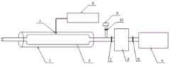
图1是本发明一个实施例的烟气中低浓度气体含量测量装置的结构示意图;以及1 is a schematic structural diagram of a device for measuring low-concentration gas content in flue gas according to an embodiment of the present invention; and
图2是本发明一个实施例的气体吸附脱附管的结构示意图;以及FIG. 2 is a schematic structural diagram of a gas adsorption and desorption tube according to an embodiment of the present invention; and
图3是本发明又一个实施例的烟气中低浓度气体含量测量装置的结构示意图。3 is a schematic structural diagram of a device for measuring low-concentration gas content in flue gas according to another embodiment of the present invention.
其中,1为加热器;2为气体吸附脱附管;3为脱附控制阀门;4为气体储存罐;5为测定控制阀门;6为气体测定仪;7为温度探测单元;8为温度控制单元;9为采样泵;10为颗粒物阻隔部件;11为气体吸附部件。Wherein, 1 is a heater; 2 is a gas adsorption and desorption tube; 3 is a desorption control valve; 4 is a gas storage tank; 5 is a measurement control valve; 6 is a gas measuring instrument; 7 is a temperature detection unit; 8 is a temperature control unit; 9 is a sampling pump; 10 is a particle blocking part; 11 is a gas adsorption part.
具体实施方式Detailed ways
下面详细描述本发明的实施例,所述实施例的示例在附图中示出,其中自始至终相同或类似的标号表示相同或类似的元件或具有相同或类似功能的元件;下面通过参考附图描述的实施例是示例性的,旨在用于解释本发明,而不能理解为对本发明的限制。The following describes in detail the embodiments of the present invention, examples of which are illustrated in the accompanying drawings, wherein the same or similar reference numerals refer to the same or similar elements or elements having the same or similar functions throughout; the following description is made with reference to the accompanying drawings The embodiments shown are exemplary and intended to explain the present invention, and should not be construed as a limitation of the present invention.
下面参考附图来详细描述根据本发明实施例的烟气中低浓度气体含量测量装置。The device for measuring low-concentration gas content in flue gas according to an embodiment of the present invention will be described in detail below with reference to the accompanying drawings.
图1是本发明一个实施例的烟气中低浓度气体含量测量装置的结构示意图;以及图2是本发明一个实施例的气体吸附脱附管的结构示意图。1 is a schematic structural diagram of a device for measuring low-concentration gas content in flue gas according to an embodiment of the present invention; and FIG. 2 is a structural schematic diagram of a gas adsorption and desorption tube according to an embodiment of the present invention.
如图1和图2所示,根据本发明实施例的烟气中低浓度气体含量测量装置,包括气体吸附脱附管2,所述气体吸附脱附管2内填充有气体吸附部件11;加热器1,所述加热器1设置在所述气体吸附脱附管2的外壁上;采样泵9,所述采样泵9通过采样管道与所述气体吸附脱附管2的出口端连通,所述采样管道上安装有采样控制阀门12;气体存储罐,所述气体储存罐4的进气口通过存储管道与所述气体吸附脱附管2的出口端相连通,所述存储管道上安装有脱附控制阀门3;以及气体测定仪6,所述气体测定仪6通过测定管道与所述气体存储罐4的出气口连接且连通;所述测定管道上设置有测定控制阀门5。。As shown in FIG. 1 and FIG. 2, the device for measuring low-concentration gas content in flue gas according to an embodiment of the present invention includes a gas adsorption and
根据本专利背景技术中对现有技术所述,目前,对于浓度低于定电位电解法检出限的气体含量测定,主要通过现场采样后到测量室采用分光光度法测定,费时费力,效率较低;而本发明的烟气中低浓度气体含量测量装置,气体吸附过程中,采样控制阀门12打开,脱附控制阀门3关闭,测定控制阀门5关闭,将气体吸附脱附管2的进气端探入至待测气路中,采样泵9提供动力使待测气体进入气体吸附脱附管2中,通过气体吸附脱附管2中的气体吸附部件11富集气体中的目标物,使得该目标物的浓度高于检出限,同时气体吸附脱附管2两端的颗粒物阻隔部件10阻挡带电的烟尘颗粒进入气体吸附脱附管2,从而避免该颗粒进入气体测定仪6中以保护气体测定仪6;富集预定时间后,将气体吸附脱附管2的进气端封闭,关闭采样控制阀门12、打开脱附控制阀门3,并通过加热管加热,将富集在气体吸附脱附管2中的目标物全部脱附并进入气体储存罐4,同时温度探测单元7探测气体吸附脱附管2外壁温度,温度控制单元8根据探测单元探测到的温度控制加热器1的加热,脱附预定时间后,关闭脱附控制阀门3、开启测定控制阀门5,即可在现场即可使用气体测定仪6采用定电位电解法将目标物浓度检测出来,大大提高了测量效率。According to the prior art described in the background of this patent, at present, for the determination of gas content whose concentration is lower than the detection limit of the constant-potential electrolysis method, the spectrophotometric method is mainly used for on-site sampling in the measurement room, which is time-consuming and labor-intensive, and the efficiency is relatively low. And the low-concentration gas content measuring device in the flue gas of the present invention, in the gas adsorption process, the
另外,根据本发明上述实施例的烟气中低浓度气体含量测量装置还可以具有如下附加的技术特征:In addition, the device for measuring low-concentration gas content in flue gas according to the above embodiments of the present invention may also have the following additional technical features:
根据本发明的一个实施例,所述烟气中低浓度气体含量测量装置还包括用于探测所述气体吸附脱附管2外壁温度的温度探测单元7,所述温度探测单元7设置在所述气体吸附脱附管2外壁上;以及用于控制所述气体吸附脱附管2外壁温度的温度控制单元8,所述温度控制单元8与所述温度探测单元7以及所述加热器1连接。According to an embodiment of the present invention, the low-concentration gas content measurement device in the flue gas further includes a temperature detection unit 7 for detecting the temperature of the outer wall of the gas adsorption and
根据本发明的一个实施例,所述烟气中低浓度气体含量测量装置还包括脱附动力泵13和动力泵控制阀门14;所述存储管道上依次设置有所述脱附控制阀门3、所述脱附动力泵13和所述动力泵控制阀门14;所述动力泵控制阀门14的另一端与所述气体储存罐4的进气口连接且连通。According to an embodiment of the present invention, the low-concentration gas content measurement device in the flue gas further includes a desorption power pump 13 and a power pump control valve 14; the storage pipeline is provided with the desorption control valve 3, the The desorption power pump 13 and the power pump control valve 14 ; the other end of the power pump control valve 14 is connected and communicated with the air inlet of the gas storage tank 4 .
根据本发明的一个实施例,所述动力泵控制阀门14为截止阀。According to an embodiment of the present invention, the power pump control valve 14 is a stop valve.
根据本发明的一个实施例,加热器1包括加热管,所述加热管套设在所述气体吸附脱附管2的外部;以及设置在所述加热管管壁内的加热电阻丝。According to an embodiment of the present invention, the heater 1 includes a heating tube sleeved on the outside of the gas adsorption and
根据本发明的一个实施例,所述气体吸附脱附管2的两端口覆盖有颗粒物阻隔部件10。According to an embodiment of the present invention, the two ports of the gas adsorption and
根据本发明的一个实施例,所述颗粒物阻隔部件10为由玻璃棉和/或石英棉制成的阻隔部件。According to an embodiment of the present invention, the
根据本发明的一个实施例,所述气体吸附部件11为由活性炭、Na型分子筛、ZSM-5、13X、SAPO、Y型等分子筛中的至少一种吸附材质制成的气体吸附部件11。According to an embodiment of the present invention, the
根据本发明的一个实施例,所述气体吸附部件11的粒径为10目-40目,优选为20-30目。According to an embodiment of the present invention, the particle size of the
根据本发明的一个实施例,所述气体吸附部件11为经过高温焙烧预处理再待保干冷却后的吸附部件,以提高吸附效率。According to an embodiment of the present invention, the
根据本发明的一个实施例,所述焙烧温度为400-600度,焙烧时间为1-3h。According to an embodiment of the present invention, the roasting temperature is 400-600 degrees, and the roasting time is 1-3 hours.
优选地,焙烧温度为500度,焙烧时间为2h。Preferably, the roasting temperature is 500 degrees, and the roasting time is 2h.
通过焙烧对气体吸附部件进行活化;去除气体吸附部件中的水分以及表面吸附的一些其他物质,以释放出更多的吸附点位,用以吸附目标组分。The gas adsorption part is activated by roasting; the moisture in the gas adsorption part and some other substances adsorbed on the surface are removed to release more adsorption sites for adsorbing the target components.
通过气体吸附部件11不仅可吸附目标物,同时对水分也有很大的吸附作用,能很好的适应烟气湿度较大的采样。The
通过设置气体吸附部件11的粒径和焙烧温度以提高气体吸附部件11的吸收效率,以防待测气体进入采样泵9。By setting the particle size and firing temperature of the
根据本发明的一个实施例,所述加热器1的的最高加热温度600℃。According to an embodiment of the present invention, the maximum heating temperature of the heater 1 is 600°C.
根据本发明的一个实施例,所述采样控制阀门12为截止阀,所述脱附控制阀门3为止回阀。According to an embodiment of the present invention, the
根据本发明的一个实施例,所述气体储存罐4的容积为100mL-10L。According to an embodiment of the present invention, the volume of the gas storage tank 4 is 100mL-10L.
根据本发明的一个实施例,所述气体测定仪6为直读式气体测定仪。According to an embodiment of the present invention, the gas measuring instrument 6 is a direct-reading gas measuring instrument.
根据本发明的一个实施例,所述测定控制阀门5为止回阀。According to one embodiment of the present invention, the assay control valve 5 is a non-return valve.
根据本发明的另一方面,还提供了一种基于上述烟气中低浓度气体含量测量装置的低浓度气体浓度探测方法,包括以下步骤:According to another aspect of the present invention, there is also provided a low-concentration gas concentration detection method based on the above-mentioned device for measuring low-concentration gas content in flue gas, comprising the following steps:
气体吸附步骤,打开采样控制阀门12,关闭脱附控制阀门3和测定控制阀门5;采样泵9提供动力使待测气体进入气体吸附脱附管2中;In the gas adsorption step, open the
脱附步骤,气体吸附经过预定吸附时间,将气体吸附脱附管2的进气端封闭,关闭采样控制阀门12、打开脱附控制阀门3,加热管对气体吸附脱附管2加热,同时温度探测单元7探测气体吸附脱附管2外壁温度,温度控制单元8根据探测单元探测到的温度控制加热器1的加热;In the desorption step, after the gas adsorption has passed a predetermined adsorption time, the inlet end of the gas adsorption and
测定步骤,气体脱附经过预定脱附时间,关闭脱附控制阀门3、开启测定控制阀门5,通过气体测定仪6测定气体储存罐4储存的目标物浓度,最终计算得到待测气体中的目标物浓度,计算公式如下:待测气体中的目标物浓度=(气体测定仪读数*气体储存罐体积 )/(吸附时采样流量*预定吸附时间)。In the measurement step, the gas is desorbed after a predetermined desorption time, the desorption control valve 3 is closed, the measurement control valve 5 is opened, and the concentration of the target substance stored in the gas storage tank 4 is measured by the gas measuring instrument 6, and the target in the gas to be measured is finally calculated. The calculation formula is as follows: the concentration of the target substance in the gas to be measured = (the reading of the gas analyzer * the volume of the gas storage tank) / (the sampling flow during adsorption * the predetermined adsorption time).
根据本发明的一个实施例,所述脱附步骤中,打开脱附控制阀门3和动力泵控制阀门14,并打开脱附动力泵13,加热管对气体吸附脱附管2加热;所述测定步骤中,气体脱附经过预定脱附时间,关闭脱附控制阀门3和所述动力泵控制阀门14、开启测定控制阀门5。According to an embodiment of the present invention, in the desorption step, the desorption control valve 3 and the power pump control valve 14 are opened, and the desorption power pump 13 is turned on, and the heating pipe heats the gas adsorption and
做具体测试例和对比例如下:The specific test cases and comparisons are as follows:
测试例一:测定浓度为1.0mg/m3的一氧化氮标准气体。Test Example 1: Determination of nitric oxide standard gas with a concentration of 1.0 mg/m3 .
样品吸附:采用20目的13X分子筛作为气体吸附部件11,通过采样泵9控制进入气体吸附脱附管2的流量为10mL/min,预定吸附时间为4min。Sample adsorption: 20 mesh 13X molecular sieve was used as the
样品脱附:控制气体吸附脱附管2外壁温度为500℃,预定脱附时间为2min,气体储存罐4容积为10mL。Sample desorption: control the temperature of the outer wall of the gas adsorption and
样品测试:气体测定仪6读数为4mg/m3。Sample testing: Gas analyzer 6 reads 4 mg/m3 .
样品结果:经计算,原浓度气体为1.0mg/m3。Sample result: After calculation, the original concentration of gas is 1.0 mg/m3 .
结论:由上面测试例可以看出本发明的烟气中低浓度气体含量测量装置和测量方法能够快速准确地测量出低浓度一氧化氮气体的含量。Conclusion: It can be seen from the above test examples that the low-concentration gas content measuring device and measuring method in the flue gas of the present invention can quickly and accurately measure the low-concentration nitric oxide gas content.
对比例一:测定含湿量为25%(模拟烟气采样)、浓度为100mg/m3的二氧化硫标准气体。Comparative Example 1: Determination of sulfur dioxide standard gas with a moisture content of 25% (simulated flue gas sampling) and a concentration of 100 mg/m3 .
样品采集:采用相同时间,相同流速,采集以上二氧化硫标准气体,分别于甲醛缓冲溶液吸收管(以100ml/min流速采集4min)和本发明的气体含量测量设备(以100ml/min采集4min;使用Y型分子筛进行气体吸附部件11,气体储存罐4的体积为100mL)中。Sample collection: adopt the same time, the same flow rate, collect the above sulfur dioxide standard gas, respectively in the formaldehyde buffer solution absorption tube (collect 4min at 100ml/min flow rate) and the gas content measuring device of the present invention (collect 4min at 100ml/min; use Y Type molecular sieve is carried out in the
样品测试:(1)采用《空气和废气监测分析方法》(第四版增补版)第五篇第四章(一)甲醛缓冲溶液吸收-盐酸副玫瑰苯胺分光光度法中所述方法进行样品的测定;(2)采用本发明的气体含量测量设备:控制气体吸附脱附管2脱附时的外壁温度为500℃,预定脱附时间为1min;并采用直读式气体测定仪进行检测。Sample test: (1) Use the method described in Chapter 4 (1) Formaldehyde Buffer Solution Absorption-Pararosaniline Hydrochloride Spectrophotometry of "Air and Waste Gas Monitoring and Analysis Methods" (4th Edition Supplementary Edition) to conduct sample analysis. (2) Using the gas content measuring equipment of the present invention: control the outer wall temperature of the gas adsorption and
样品结果:(1)甲醛缓冲溶液吸收-盐酸副玫瑰苯胺分光光度法测定结果为85.0mg/m3;(2)使用本案的气体含量测量设备的测定结果为98mg/m3。Sample results: (1) The formaldehyde buffer solution absorption-pararosaniline hydrochloride spectrophotometric measurement result was 85.0 mg/m3 ; (2) The measurement result using the gas content measuring equipment in this case was 98 mg/m3 .
结论:采用本发明的烟气中低浓度气体含量测量装置和测量方法能够采集湿度较大的烟气,且测定结果较为准确。Conclusion: The low-concentration gas content measuring device and measuring method in the flue gas of the present invention can collect flue gas with high humidity, and the measurement results are more accurate.
对比例二:Comparative example 2:
采用Na型分子筛、ZSM-5、13X、Y型4种不同的吸附材料作为气体吸附部件11(其他测定条件相同),对浓度为100mg/m3的一氧化氮标准气体进行测定,测定结果如表1所示:Four different adsorption materials, Na-type molecular sieve, ZSM-5, 13X, and Y-type, were used as the gas adsorption component 11 (other measurement conditions were the same), and the standard gas of nitric oxide with a concentration of 100 mg/m3 was measured. The measurement results are as follows Table 1 shows:
表1 不同吸附材料测定一氧化氮的检测结果
结论:由表1可知,使用13X作为气体吸附部件11测量得到的一氧化氮浓度最为准确。Conclusion: It can be seen from Table 1 that the nitric oxide concentration measured by using 13X as the
对比例三:Comparative example three:
分别采用10目、20目、30目、40目4种规格的13X分子筛作为气体吸附部件11,在相同条件下测定浓度为1.0mg/m3的一氧化氮标准气体;经计算,测定结果如表2所示:13X molecular sieves with 4 specifications of 10 mesh, 20 mesh, 30 mesh and 40 mesh were respectively used as the
表2 不同规格分子筛测定一氧化氮的检测结果
结论:由表2可知,使用20目和30目13X作为气体吸附部件11测量得到的一氧化氮浓度最为准确。Conclusion: It can be seen from Table 2 that the nitric oxide concentration measured by using 20 mesh and 30 mesh 13X as the
对比例四:采用20目的13X分子筛作为气体吸附部件,分别采用400℃、500℃、600℃对气体吸附部件焙烧1h,在相同测定条件下测定浓度为1.0mg/m3的一氧化氮标准气体;经计算,测定结果如表3:Comparative Example 4: Using 20-mesh 13X molecular sieve as the gas adsorption component, calcining the gas adsorption component at 400°C, 500°C, and 600°C for 1 hour, and measuring the nitric oxide standard gas with a concentration of 1.0 mg/m3 under the same measurement conditions; After calculation, the measurement results are shown in Table 3:
表3 不同焙烧温度处理后13X分子筛测定一氧化氮的检测结果
结论:由表3可知,使用500度焙烧的13X作为气体吸附部件11测量得到的一氧化氮浓度最为准确。Conclusion: It can be seen from Table 3 that the nitric oxide concentration measured by using 13X calcined at 500 degrees as the
对比例五:采用20目的13X分子筛作为气体吸附部件,采用500℃分别对三份相同的气体吸附部件焙烧1h、2h、3h,在相同测定条件下测定浓度为1.0mg/m3的一氧化氮标准气体;经计算,测定结果如表4:Comparative Example 5: Using 20 mesh 13X molecular sieve as the gas adsorption component, calcining three identical gas adsorption components at 500°C for 1h, 2h, and 3h respectively, and measuring the nitric oxide standard with a concentration of 1.0mg/m3 under the same measurement conditions Gas; after calculation, the measurement results are shown in Table 4:
表4 不同焙烧时间处理后13X分子筛测定一氧化氮的检测结果
结论:由表4可知,焙烧时间为2h的13X作为气体吸附部件11测量得到的一氧化氮浓度最为准确。Conclusion: It can be seen from Table 4 that the nitric oxide concentration measured by 13X with a calcination time of 2h as the
在本发明的描述中,需要理解的是,术语 “上”、“下”、“前”、“后”、等指示的方位或位置关系为基于附图所示的方位或位置关系,仅是为了便于描述本发明和简化描述,而不是指示或暗示所指的装置或元件必须具有特定的方位、以特定的方位构造和操作,因此不能理解为对本发明的限制。In the description of the present invention, it should be understood that the orientation or positional relationship indicated by the terms "upper", "lower", "front", "rear", etc. is based on the orientation or positional relationship shown in the accompanying drawings, only In order to facilitate the description of the present invention and simplify the description, it is not indicated or implied that the indicated device or element must have a particular orientation, be constructed and operated in a particular orientation, and therefore should not be construed as limiting the present invention.
在本发明中,除非另有明确的规定和限定,术语“安装”、“相连”、“连接”、“固定”等术语应做广义理解,例如,可以是固定连接,也可以是可拆卸连接,或成一体;可以是机械连接,也可以是电连接;可以是直接相连,也可以通过中间媒介间接相连,可以是两个元件内部的连通或两个元件的相互作用关系。对于本领域的普通技术人员而言,可以根据具体情况理解上述术语在本发明中的具体含义。In the present invention, unless otherwise expressly specified and limited, the terms "installed", "connected", "connected", "fixed" and other terms should be understood in a broad sense, for example, it may be a fixed connection or a detachable connection , or integrated; it can be a mechanical connection or an electrical connection; it can be a direct connection or an indirect connection through an intermediate medium, and it can be the internal connection of the two elements or the interaction relationship between the two elements. For those of ordinary skill in the art, the specific meanings of the above terms in the present invention can be understood according to specific situations.
在本说明书的描述中,参考术语“一个实施例”、“一些实施例”、 “示例”、“具体示例”、或“一些示例”等的描述意指结合该实施例或示例描述的具体特征、结构、材料或者特点包含于本发明的至少一个实施例或示例中。在本说明书中,对上述术语的示意性表述不必须针对的是相同的实施例或示例。而且,描述的具体特征、结构、材料或者特点可以在任一个或多个实施例或示例中以合适的方式结合。此外,在不相互矛盾的情况下,本领域的技术人员可以将本说明书中描述的不同实施例或示例以及不同实施例或示例的特征进行结合和组合。In the description of this specification, description with reference to the terms "one embodiment," "some embodiments," "example," "specific example," or "some examples", etc., mean specific features described in connection with the embodiment or example , structure, material or feature is included in at least one embodiment or example of the present invention. In this specification, schematic representations of the above terms are not necessarily directed to the same embodiment or example. Furthermore, the particular features, structures, materials or characteristics described may be combined in any suitable manner in any one or more embodiments or examples. Furthermore, those skilled in the art may combine and combine the different embodiments or examples described in this specification, as well as the features of the different embodiments or examples, without conflicting each other.
尽管上面已经示出和描述了本发明的实施例,可以理解的是,上述实施例是示例性的,不能理解为对本发明的限制,本领域的普通技术人员在本发明的范围内可以对上述实施例进行变化、修改、替换和变型。Although the embodiments of the present invention have been shown and described above, it should be understood that the above embodiments are exemplary and should not be construed as limiting the present invention. Embodiments are subject to variations, modifications, substitutions and variations.
Claims (9)
Priority Applications (1)
| Application Number | Priority Date | Filing Date | Title |
|---|---|---|---|
| CN202010449192.XACN111781251A (en) | 2020-05-25 | 2020-05-25 | A low-concentration gas content measurement device in flue gas |
Applications Claiming Priority (1)
| Application Number | Priority Date | Filing Date | Title |
|---|---|---|---|
| CN202010449192.XACN111781251A (en) | 2020-05-25 | 2020-05-25 | A low-concentration gas content measurement device in flue gas |
Publications (1)
| Publication Number | Publication Date |
|---|---|
| CN111781251Atrue CN111781251A (en) | 2020-10-16 |
Family
ID=72753200
Family Applications (1)
| Application Number | Title | Priority Date | Filing Date |
|---|---|---|---|
| CN202010449192.XAPendingCN111781251A (en) | 2020-05-25 | 2020-05-25 | A low-concentration gas content measurement device in flue gas |
Country Status (1)
| Country | Link |
|---|---|
| CN (1) | CN111781251A (en) |
Cited By (5)
| Publication number | Priority date | Publication date | Assignee | Title |
|---|---|---|---|---|
| CN112798358A (en)* | 2020-11-27 | 2021-05-14 | 华北电力科学研究院有限责任公司 | Laboratory material thermally volatile gas sampling device |
| CN113588888A (en)* | 2021-08-23 | 2021-11-02 | 安徽砺剑防务科技有限公司 | Self-capturing toxic gas detection equipment |
| WO2023115847A1 (en)* | 2021-12-24 | 2023-06-29 | 同方威视技术股份有限公司 | Trace particle and steam detection system |
| CN117163450A (en)* | 2023-11-02 | 2023-12-05 | 上海鲁源控制设备有限公司 | Nitrogen oxide-containing polluted gas detection and sealing equipment |
| CN118510088A (en)* | 2024-06-06 | 2024-08-16 | 江苏国测检测技术有限公司 | A far infrared heating plate and preparation method thereof |
Citations (8)
| Publication number | Priority date | Publication date | Assignee | Title |
|---|---|---|---|---|
| CN203869931U (en)* | 2014-04-30 | 2014-10-08 | 北京北分瑞利分析仪器(集团)有限责任公司 | Adsorption and heat desorption device |
| CN104459053A (en)* | 2014-12-10 | 2015-03-25 | 中国科学院苏州生物医学工程技术研究所 | Gas sampling device as well as gas path system and method adopting same |
| CN107014666A (en)* | 2017-03-21 | 2017-08-04 | 西安交通大学 | A kind of micro gas enricher and preparation method thereof |
| CN108132166A (en)* | 2017-12-29 | 2018-06-08 | 清华大学 | Sample absorber, Thermal desorption chamber device, sampling module and analytical equipment |
| US20190265205A1 (en)* | 2018-02-28 | 2019-08-29 | Mls Acq, Inc. D/B/A Max Analytical Technologies | Thermal desorption tube collection system and method |
| CN110274813A (en)* | 2018-03-14 | 2019-09-24 | 广州禾信仪器股份有限公司 | Volatile organic matter enriching apparatus and method |
| CN110907260A (en)* | 2019-12-05 | 2020-03-24 | 重庆大学 | A new type of electronic nose thermal desorption system and control method for multi-channel high temperature sealing |
| CN212674823U (en)* | 2020-05-25 | 2021-03-09 | 江苏国测检测技术有限公司 | A low-concentration gas content measurement device in flue gas |
- 2020
- 2020-05-25CNCN202010449192.XApatent/CN111781251A/enactivePending
Patent Citations (8)
| Publication number | Priority date | Publication date | Assignee | Title |
|---|---|---|---|---|
| CN203869931U (en)* | 2014-04-30 | 2014-10-08 | 北京北分瑞利分析仪器(集团)有限责任公司 | Adsorption and heat desorption device |
| CN104459053A (en)* | 2014-12-10 | 2015-03-25 | 中国科学院苏州生物医学工程技术研究所 | Gas sampling device as well as gas path system and method adopting same |
| CN107014666A (en)* | 2017-03-21 | 2017-08-04 | 西安交通大学 | A kind of micro gas enricher and preparation method thereof |
| CN108132166A (en)* | 2017-12-29 | 2018-06-08 | 清华大学 | Sample absorber, Thermal desorption chamber device, sampling module and analytical equipment |
| US20190265205A1 (en)* | 2018-02-28 | 2019-08-29 | Mls Acq, Inc. D/B/A Max Analytical Technologies | Thermal desorption tube collection system and method |
| CN110274813A (en)* | 2018-03-14 | 2019-09-24 | 广州禾信仪器股份有限公司 | Volatile organic matter enriching apparatus and method |
| CN110907260A (en)* | 2019-12-05 | 2020-03-24 | 重庆大学 | A new type of electronic nose thermal desorption system and control method for multi-channel high temperature sealing |
| CN212674823U (en)* | 2020-05-25 | 2021-03-09 | 江苏国测检测技术有限公司 | A low-concentration gas content measurement device in flue gas |
Non-Patent Citations (2)
| Title |
|---|
| 张家志等: "《职业卫生》", 31 March 1999, 中国劳动出版社, pages: 23 - 24* |
| 狄春红: "《制冷技术》", 31 August 2016, 西南交通大学出版社, pages: 136* |
Cited By (7)
| Publication number | Priority date | Publication date | Assignee | Title |
|---|---|---|---|---|
| CN112798358A (en)* | 2020-11-27 | 2021-05-14 | 华北电力科学研究院有限责任公司 | Laboratory material thermally volatile gas sampling device |
| CN113588888A (en)* | 2021-08-23 | 2021-11-02 | 安徽砺剑防务科技有限公司 | Self-capturing toxic gas detection equipment |
| CN113588888B (en)* | 2021-08-23 | 2023-11-24 | 安徽砺剑防务科技有限公司 | From catching poisonous gas check out test set |
| WO2023115847A1 (en)* | 2021-12-24 | 2023-06-29 | 同方威视技术股份有限公司 | Trace particle and steam detection system |
| CN117163450A (en)* | 2023-11-02 | 2023-12-05 | 上海鲁源控制设备有限公司 | Nitrogen oxide-containing polluted gas detection and sealing equipment |
| CN117163450B (en)* | 2023-11-02 | 2024-01-30 | 上海鲁源控制设备有限公司 | Nitrogen oxide-containing polluted gas detection and sealing equipment |
| CN118510088A (en)* | 2024-06-06 | 2024-08-16 | 江苏国测检测技术有限公司 | A far infrared heating plate and preparation method thereof |
Similar Documents
| Publication | Publication Date | Title |
|---|---|---|
| CN111781251A (en) | A low-concentration gas content measurement device in flue gas | |
| CN105300744B (en) | System for flue gas NO and mercury of thermal power plant sample simultaneously and detect | |
| Deng et al. | Primary particulate emissions and secondary organic aerosol (SOA) formation from idling diesel vehicle exhaust in China | |
| CN106814163B (en) | Device and method for testing formaldehyde and VOC (volatile organic compounds) in furniture and decoration materials by bag method | |
| KR20070090508A (en) | Large chamber pollutant release material tester | |
| CN106092663A (en) | The carbonyl compound sampling apparatus of fired coal combustion source emission | |
| CN209707187U (en) | Based on the system flue gas analysis sampling of coal unit flue negative pressure and pretreatment unit | |
| CN113361110B (en) | Method for measuring release characteristic parameters of double-layer wooden furniture material | |
| CN111351884A (en) | A device for enriching and measuring nitrogen stable isotopes and method for measuring nitrogen stable isotopes in seawater | |
| WO2023246281A1 (en) | Flue gas carbon dioxide adsorbent performance detection apparatus and detection method | |
| CN205280683U (en) | Hospital ward air quality monitoring system | |
| CN212674823U (en) | A low-concentration gas content measurement device in flue gas | |
| CN104226300B (en) | A kind of SCR catalyst and preparation method thereof | |
| CN212031380U (en) | A device for enrichment and determination of nitrogen stable isotopes | |
| CN209372636U (en) | A filter efficiency testing device | |
| CN116296632A (en) | A semi-continuous rapid sampling device for trace heavy metals in flue gas | |
| CN208255159U (en) | A catalyst activity evaluation device | |
| Cornette et al. | Accurate particulate matter emission measurements from biomass combustion: A holistic evaluation of full and partial flow dilution systems | |
| CN113566309B (en) | Multifunctional indoor air purification device and method | |
| CN114674978A (en) | Adsorbent testing apparatus, adsorbent testing method, electronic device, and readable storage medium | |
| CN205374113U (en) | Volatile organic compounds's sampling system | |
| CN210465350U (en) | On-site rapid detection device for VOCs in upholstered furniture | |
| CN110411791B (en) | A particulate matter collection device for analyzing trace element high temperature enrichment performance | |
| CN106918475A (en) | Ship tail gas diluting and sampling system for particle | |
| CN209132249U (en) | An organic liquid volatilization and treatment device with controllable conditions |
Legal Events
| Date | Code | Title | Description |
|---|---|---|---|
| PB01 | Publication | ||
| PB01 | Publication | ||
| SE01 | Entry into force of request for substantive examination | ||
| SE01 | Entry into force of request for substantive examination | ||
| RJ01 | Rejection of invention patent application after publication | ||
| RJ01 | Rejection of invention patent application after publication | Application publication date:20201016 |