CN111772917A - A scleral lamellar knife - Google Patents
A scleral lamellar knifeDownload PDFInfo
- Publication number
- CN111772917A CN111772917ACN202010650305.2ACN202010650305ACN111772917ACN 111772917 ACN111772917 ACN 111772917ACN 202010650305 ACN202010650305 ACN 202010650305ACN 111772917 ACN111772917 ACN 111772917A
- Authority
- CN
- China
- Prior art keywords
- knife
- assembly
- seat
- cutting
- blade
- Prior art date
- Legal status (The legal status is an assumption and is not a legal conclusion. Google has not performed a legal analysis and makes no representation as to the accuracy of the status listed.)
- Pending
Links
Images

Classifications
- A—HUMAN NECESSITIES
- A61—MEDICAL OR VETERINARY SCIENCE; HYGIENE
- A61F—FILTERS IMPLANTABLE INTO BLOOD VESSELS; PROSTHESES; DEVICES PROVIDING PATENCY TO, OR PREVENTING COLLAPSING OF, TUBULAR STRUCTURES OF THE BODY, e.g. STENTS; ORTHOPAEDIC, NURSING OR CONTRACEPTIVE DEVICES; FOMENTATION; TREATMENT OR PROTECTION OF EYES OR EARS; BANDAGES, DRESSINGS OR ABSORBENT PADS; FIRST-AID KITS
- A61F9/00—Methods or devices for treatment of the eyes; Devices for putting in contact-lenses; Devices to correct squinting; Apparatus to guide the blind; Protective devices for the eyes, carried on the body or in the hand
- A61F9/007—Methods or devices for eye surgery
- A61F9/00781—Apparatus for modifying intraocular pressure, e.g. for glaucoma treatment
Landscapes
- Health & Medical Sciences (AREA)
- Ophthalmology & Optometry (AREA)
- Heart & Thoracic Surgery (AREA)
- Surgery (AREA)
- Engineering & Computer Science (AREA)
- Biomedical Technology (AREA)
- Nuclear Medicine, Radiotherapy & Molecular Imaging (AREA)
- Vascular Medicine (AREA)
- Life Sciences & Earth Sciences (AREA)
- Animal Behavior & Ethology (AREA)
- General Health & Medical Sciences (AREA)
- Public Health (AREA)
- Veterinary Medicine (AREA)
- Surgical Instruments (AREA)
Abstract
Translated fromChinese
Description
Translated fromChinese技术领域technical field
本发明涉及青光眼治疗技术领域,特别涉及一种巩膜板层刀。The invention relates to the technical field of glaucoma treatment, in particular to a scleral lamellar knife.
背景技术Background technique
目前现有的制作巩膜瓣的方式是通过医生用巩膜隧道刀在巩膜上切割出巩膜瓣,切割精度无法保证,且由于是手动控制,靠经验和手法来切割出巩膜瓣,切割后眼球表面凹凸不平,手术失败风险高,并且,切割比较依赖医护人员技术娴熟程度,切割效率较低。At present, the existing method of making a scleral flap is to cut the scleral flap on the sclera by a doctor using a scleral tunnel knife. The cutting accuracy cannot be guaranteed, and because of manual control, the scleral flap is cut out by experience and techniques, and the surface of the eyeball is uneven after cutting. Uneven, the risk of surgical failure is high, and the cutting is more dependent on the skill of medical staff, and the cutting efficiency is low.
发明内容SUMMARY OF THE INVENTION
本发明所要解决的技术问题是提供一种巩膜板层刀,有效的克服了现有技术的缺陷。The technical problem to be solved by the present invention is to provide a scleral lamina knife, which effectively overcomes the defects of the prior art.
本发明解决上述技术问题的技术方案如下:The technical scheme that the present invention solves the above-mentioned technical problems is as follows:
一种巩膜板层刀,包括刀座、刀架组件、切割座和冲量发生机构,上述刀座内部中空,其前端设有供上述刀架组件穿过的孔位,上述切割座装配于上述刀座的前端,上述切割座一侧开有延伸至其后端端部并与上述孔位对应的切割槽,上述刀座内部安装有吸盘组件,且该吸盘组件的吸附面置于上述切割槽的槽底处,上述刀架组件前后贯穿上述孔位,其前端设有与上述切割槽相匹配的刀片,上述冲量发生机构装配于上述刀座中,用于驱使上述刀架组件带动上述刀片向前移动至上述切割槽中,从而切割由上述吸盘组件吸入切割槽中的巩膜。A scleral plate knife, comprising a knife seat, a knife holder assembly, a cutting seat and an impulse generating mechanism, wherein the inside of the above-mentioned knife holder is hollow, the front end of which is provided with a hole for the above-mentioned knife holder assembly to pass through, and the above-mentioned cutting seat is assembled on the above-mentioned knife At the front end of the seat, one side of the above-mentioned cutting seat is provided with a cutting groove extending to its rear end and corresponding to the above-mentioned hole position, and a suction cup assembly is installed inside the above-mentioned knife seat, and the suction surface of the suction cup assembly is placed in the above-mentioned cutting groove. At the bottom of the groove, the above-mentioned tool holder assembly runs through the above-mentioned hole positions before and after, and its front end is provided with a blade that matches the above-mentioned cutting groove. Move into the cutting groove, thereby cutting the sclera sucked into the cutting groove by the suction cup assembly.
在上述技术方案的基础上,本发明还可以做如下改进。On the basis of the above technical solutions, the present invention can also be improved as follows.
进一步,上述冲量发生机构包括手柄和弹性件,上述弹性件连接于上述刀座内腔的后端与上述刀架组件的后端之间,上述刀座上沿前后方向设有供上述手柄穿过并滑行的滑孔,上述手柄穿过上述滑孔,并与上述刀架组件的后端连接固定,上述手柄可在外力作用下向后拉动,并带动上述刀架组件向后移动至刀片脱离上述切割槽,并压缩上述弹性件,撤销外力后,上述弹性件恢复初始状态,并驱使上述刀架组件带动刀片向前移动至上述切割槽中。Further, the above-mentioned impulse generating mechanism includes a handle and an elastic member, the above-mentioned elastic member is connected between the rear end of the inner cavity of the above-mentioned knife holder and the rear end of the above-mentioned knife holder assembly, and the above-mentioned knife holder is provided with a front and rear direction for the above-mentioned handle to pass through. The sliding hole for sliding and sliding, the handle passes through the sliding hole, and is connected and fixed with the rear end of the knife holder assembly, the handle can be pulled backward under the action of external force, and drives the knife holder assembly to move backward until the blade is separated from the above-mentioned cut the groove and compress the elastic piece. After the external force is removed, the elastic piece returns to the initial state and drives the knife holder assembly to drive the blade to move forward into the cutting groove.
进一步,上述冲量发生机构还包括定位组件,上述定位组件装配于上述刀座上,其用于在上述刀架组件带动刀片向后移动至脱离上述切割槽后对其定位保持其当前位置。Further, the above-mentioned impulse generating mechanism further includes a positioning assembly, which is assembled on the above-mentioned knife seat, and is used for positioning and maintaining the current position of the blade after the above-mentioned knife holder assembly drives the blade to move backwards to be separated from the above-mentioned cutting groove.
进一步,上述定位组件包括限位卡块和限位柱,上述限位卡块可拆卸的装配于上述刀座上对应上述刀架组件后端移动轨迹后方的位置,其上设有延伸至其端部并与上述手柄相卡合的卡口,上述限位卡块装配于上述刀座上,并用于与上述限位卡块的前端相抵,当上述刀架组件带动上述刀片向后移动至极限位置时,上述限位卡块可装配于上述刀座上,并通过卡口与上述手柄相互卡合,且与上述限位卡块后端相抵,从而保持上述刀架组件的当前位置。Further, the above-mentioned positioning assembly includes a limit block and a limit post, the above-mentioned limit block is detachably assembled on the above-mentioned tool holder corresponding to the position behind the movement track of the rear end of the above-mentioned tool holder assembly, and there are provided on it extending to its end. A bayonet that engages with the handle, the limit block is assembled on the knife seat, and is used to abut the front end of the limit block, when the knife block assembly drives the blade to move backwards to the limit position At the time, the limit block can be assembled on the knife holder, and engage with the handle through the bayonet, and abut against the rear end of the limit block, so as to maintain the current position of the knife block assembly.
进一步,上述刀座的左右两侧分别沿前后方向设有上述滑孔,相应的上述刀座左右两侧分别一一对应的设有穿过两侧滑孔的上述手柄,上述限位卡块为开口朝下的U形卡块,其两侧分别设有竖直向下延伸至其下端端部的上述卡口。Further, the left and right sides of the above-mentioned knife holder are respectively provided with the above-mentioned sliding holes along the front-rear direction, and the corresponding left and right sides of the above-mentioned knife holder are respectively provided with the above-mentioned handles passing through the sliding holes on both sides, and the above-mentioned limit blocks are: The two sides of the U-shaped clamping block with its opening facing downward are respectively provided with the above-mentioned bayonet openings extending vertically downward to the lower end portion thereof.
进一步,上述刀座内腔眼前后方向设有导向杆,上述刀架组件的后端设有套设于上述导向杆外的滑动部,上述弹性件连接于上述刀座内腔的后端与上述滑动部的后端之间。Further, a guide rod is provided in the front and rear directions of the inner cavity of the knife seat, the rear end of the knife block assembly is provided with a sliding part sleeved outside the guide rod, and the elastic member is connected to the rear end of the inner cavity of the knife seat and the above-mentioned between the rear ends of the sliding parts.
进一步,上述弹性件为套设于上述导向杆外的弹簧。Further, the elastic member is a spring sleeved outside the guide rod.
本发明的有益效果是:改善了传统手术采用人工切割巩膜瓣大小不均匀,操作复杂,且效率低的问题,操作简单、方便,切割效率高,质量好。The beneficial effects of the invention are as follows: the problems of uneven size, complex operation and low efficiency of manual cutting of the scleral flap in traditional surgery are improved, the operation is simple and convenient, the cutting efficiency is high, and the quality is good.
附图说明Description of drawings
图1为本发明的巩膜板层刀的结构示意图;Fig. 1 is the structural representation of the scleral lamina knife of the present invention;
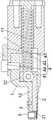
图2本发明的巩膜板层刀的结构剖视图。Fig. 2 is a cross-sectional view of the structure of the scleral lamina knife of the present invention.
附图中,各标号所代表的部件列表如下:In the accompanying drawings, the list of components represented by each number is as follows:
1、刀座,2、刀架组件,3、切割座,4、冲量发生机构,5、吸盘组件,11、导向杆,12、安装部,21、刀片,22、滑动部,31、切割槽,41、手柄,42、弹性件,43、限位卡块,44、限位柱,431、卡口。1. Tool seat, 2. Tool rest assembly, 3. Cutting seat, 4. Impulse generating mechanism, 5. Suction cup assembly, 11. Guide rod, 12. Mounting part, 21, Blade, 22, Sliding part, 31, Cutting groove , 41, handle, 42, elastic piece, 43, limit block, 44, limit post, 431, bayonet.
具体实施方式Detailed ways
以下结合附图对本发明的原理和特征进行描述,所举实例只用于解释本发明,并非用于限定本发明的范围。The principles and features of the present invention will be described below with reference to the accompanying drawings. The examples are only used to explain the present invention, but not to limit the scope of the present invention.
实施例:如图1和2所示,本实施例的巩膜板层刀包括刀座1、刀架组件2、切割座3和冲量发生机构4,上述刀座1内部中空,其前端设有供上述刀架组件2穿过的孔位,上述切割座3装配于上述刀座1的前端,上述切割座3一侧开有延伸至其后端端部并与上述孔位对应的切割槽31,上述刀座1内部安装有吸盘组件5,且该吸盘组件5的吸附面置于上述切割槽31的槽底处,上述刀架组件2前后贯穿上述孔位,其前端设有与上述切割槽31相匹配的刀片21,上述冲量发生机构4装配于上述刀座1中,用于驱使上述刀架组件2带动上述刀片21向前移动至上述切割槽31中,从而切割由上述吸盘组件5吸入切割槽31中的巩膜。Embodiment: As shown in Figures 1 and 2, the scleral lamina knife of this embodiment includes a
手术过程如下:The procedure is as follows:
1)手术前,刀架组件2相对于刀座1向后移动,使刀片21脱离切割槽31(或是完全避让开切割槽31);1) Before the operation, the
2)将器械头部的切割槽31扣压在眼球巩膜处,通过与吸盘组件5连接的抽真空装置使得吸盘组件5的吸附面产生负压,让切割座3头部吸附在巩膜上;2) Press the
3)等负压稳定后,冲量发生机构4驱使刀架组件2带动刀片21向前快速移动,给刀片一个冲量,使得刀片21向前滑入切割槽31中,并切开巩膜瓣。3) After the negative pressure is stabilized, the impulse generating mechanism 4 drives the
整个装置改善了传统手术采用人工切割巩膜瓣大小不均匀,操作复杂,且效率低的问题,操作简单、方便,切割效率高,质量好。The whole device improves the problems of uneven size, complicated operation and low efficiency of manual cutting of the scleral flap in traditional surgery. The operation is simple and convenient, and the cutting efficiency is high and the quality is good.
上述刀座1内设有与吸盘组件5相匹配的装配腔,吸盘组件5采用常规的吸盘件(具体结构在此不做赘述)。The above-mentioned
更佳的,在刀座1前端位于孔位任意一侧的位置设有向前延伸的条状的安装部12,切割座3装配于安装部12的前端。More preferably, a strip-
上述切割槽31可以根据切割的规格设计不同尺寸,但最佳的应设计为方形槽,相应的刀片21为与其匹配的长方形刀片(前后延伸并竖向设置),例如:切割槽31规格为4mm×4mm,深度为0.3mm,刀片的宽度接近4mm。The above-mentioned
作为一种优选的实施方式,上述冲量发生机构4包括手柄41和弹性件42,上述弹性件42连接于上述刀座1内腔的后端与上述刀架组件2的后端之间,上述刀座1上沿前后方向设有供上述手柄41穿过并滑行的滑孔,上述手柄41穿过上述滑孔,并与上述刀架组件2的后端连接固定,上述手柄41可在外力作用下向后拉动,并带动上述刀架组件2向后移动至刀片21脱离上述切割槽31,并压缩上述弹性件42,撤销外力后,上述弹性件42恢复初始状态,并驱使上述刀架组件2带动刀片21向前移动至上述切割槽31中。As a preferred embodiment, the impulse generating mechanism 4 includes a
该实施方式的操作过程如下:The operation process of this embodiment is as follows:
1)通过拉操作手柄41,让刀架组件2克服弹性件42的弹力向后运动,运动到极限位置;1) By pulling the
2)将器械头部的切割槽31扣压在眼球巩膜处,通过与吸盘组件5连接的抽真空装置使得吸盘组件5的吸附面产生负压,让切割座3头部吸附在巩膜上;2) Press the
3)等负压稳定后,弹性件42恢复初始状态,并驱使刀架组件2带动刀片21向前快速移动,给刀片一个冲量,使得刀片21向前滑入切割槽31中,并切开巩膜瓣。3) After the negative pressure is stabilized, the
整个操作过程比较简单、通过拉动手柄41即可完成,非常之方便。The whole operation process is relatively simple and can be completed by pulling the
作为一种优选的实施方式,上述冲量发生机构4还包括定位组件,上述定位组件装配于上述刀座1上,其用于在上述刀架组件2带动刀片21向后移动至脱离上述切割槽31后对其定位保持其当前位置。As a preferred embodiment, the above-mentioned impulse generating mechanism 4 further includes a positioning assembly, and the above-mentioned positioning assembly is assembled on the above-mentioned
该实施方式中,定位组件的设计能够使得刀架组件2带动刀片21移动至后方极限位置后通过其保持当前位置,从而解放医护人员对刀架组件2的手动定位,使得操作更简单、方便。In this embodiment, the design of the positioning assembly enables the
作为一种优选的实施方式,上述定位组件包括限位卡块43和限位柱44,上述限位卡块43可拆卸的装配于上述刀座1上对应上述刀架组件2后端移动轨迹后方的位置,其上设有延伸至其端部并与上述手柄41相卡合的卡口431,上述限位卡块43装配于上述刀座1上,并用于与上述限位卡块43的前端相抵,当上述刀架组件2带动上述刀片21向后移动至极限位置时,上述限位卡块43可装配于上述刀座1上,并通过卡口431与上述手柄41相互卡合,且与上述限位卡块43后端相抵,从而保持上述刀架组件2的当前位置。As a preferred embodiment, the positioning assembly includes a
该实施方式中,定位组件结构设计简单,利用限位卡快43对手柄41进行位置限制,再通过限位柱44限制相关构件向前的位移,从而达到对刀架组件2位置保持定位的目的,操作比较简单、快捷。In this embodiment, the structural design of the positioning assembly is simple, the position of the
作为一种优选的实施方式,如图1所示,上述刀座1的左右两侧分别沿前后方向设有上述滑孔,相应的上述刀座1左右两侧分别一一对应的设有穿过两侧滑孔的上述手柄41,上述限位卡块43为开口朝下的U形卡块,其两侧分别设有竖直向下延伸至其下端端部的上述卡口431。As a preferred embodiment, as shown in FIG. 1 , the left and right sides of the
该实施方式中,限位卡块43采用上下插装的方式,操作比较快捷、灵活,并且,采用两侧分别设置手柄41的结构,使得通过手柄41对刀架组件2的拉动过程受力比较平稳、均匀,移动比较顺畅,不易发生卡顿的现象。In this embodiment, the
作为一种优选的实施方式,上述刀座1内腔眼前后方向设有导向杆11,上述刀架组件2的后端设有套设于上述导向杆11外的滑动部22,上述弹性件42连接于上述刀座1内腔的后端与上述滑动部22的后端之间。As a preferred embodiment, the inner cavity of the
该实施方式中,导向杆11及滑动部22的相互配合设计,使得刀架组件2的前后移动能够沿导向杆11正确的滑动,不会发生刀架组件2的左右上下晃动的情况,从而确保刀片21在切割槽31内对巩膜的切割动作比较标准,也就是切割的效率及质量得到有效的保障。In this embodiment, the
作为一种优选的实施方式,上述弹性件42为套设于上述导向杆11外的弹簧。As a preferred embodiment, the
该实施方式中,弹簧套设于导向杆11外,其布置比较稳定,并且在收到外力压缩时,其压缩方向能够沿导向杆11良好的向后压缩,使得后续释放后确保刀架组件2能良好的向前移动切割。In this embodiment, the spring is sleeved outside the
当然,需要说明的是:整个器材中,冲量发生机构4可以采用完整的电动伸缩机构来实现自动化的运行。Of course, it should be noted that: in the whole equipment, the impulse generating mechanism 4 can use a complete electric telescopic mechanism to realize automatic operation.
以上所述仅为本发明的较佳实施例,并不用以限制本发明,凡在本发明的精神和原则之内,所作的任何修改、等同替换、改进等,均应包含在本发明的保护范围之内。The above are only preferred embodiments of the present invention and are not intended to limit the present invention. Any modifications, equivalent replacements, improvements, etc. made within the spirit and principles of the present invention shall be included in the protection of the present invention. within the range.
Claims (7)
Translated fromChinesePriority Applications (1)
| Application Number | Priority Date | Filing Date | Title |
|---|---|---|---|
| CN202010650305.2ACN111772917A (en) | 2020-07-08 | 2020-07-08 | A scleral lamellar knife |
Applications Claiming Priority (1)
| Application Number | Priority Date | Filing Date | Title |
|---|---|---|---|
| CN202010650305.2ACN111772917A (en) | 2020-07-08 | 2020-07-08 | A scleral lamellar knife |
Publications (1)
| Publication Number | Publication Date |
|---|---|
| CN111772917Atrue CN111772917A (en) | 2020-10-16 |
Family
ID=72759300
Family Applications (1)
| Application Number | Title | Priority Date | Filing Date |
|---|---|---|---|
| CN202010650305.2APendingCN111772917A (en) | 2020-07-08 | 2020-07-08 | A scleral lamellar knife |
Country Status (1)
| Country | Link |
|---|---|
| CN (1) | CN111772917A (en) |
Citations (5)
| Publication number | Priority date | Publication date | Assignee | Title |
|---|---|---|---|---|
| GB1286339A (en)* | 1969-07-15 | 1972-08-23 | Herman George Bender | Surgical cutter |
| RU94015005A (en)* | 1994-04-22 | 1996-08-10 | Казанский медико-инструментальный завод | Ophthalmologic instrument |
| US5669923A (en)* | 1996-01-24 | 1997-09-23 | Gordon; Mark G. | Anterior capsulotomy device and procedure |
| CN101032419A (en)* | 2006-03-07 | 2007-09-12 | 伊西康内外科公司 | Device for minimally invasive internal tissue removal |
| CN102626329A (en)* | 2012-03-13 | 2012-08-08 | 郑州大学 | Radiofrequency ablation negative pressure automatic biopsy gun |
- 2020
- 2020-07-08CNCN202010650305.2Apatent/CN111772917A/enactivePending
Patent Citations (5)
| Publication number | Priority date | Publication date | Assignee | Title |
|---|---|---|---|---|
| GB1286339A (en)* | 1969-07-15 | 1972-08-23 | Herman George Bender | Surgical cutter |
| RU94015005A (en)* | 1994-04-22 | 1996-08-10 | Казанский медико-инструментальный завод | Ophthalmologic instrument |
| US5669923A (en)* | 1996-01-24 | 1997-09-23 | Gordon; Mark G. | Anterior capsulotomy device and procedure |
| CN101032419A (en)* | 2006-03-07 | 2007-09-12 | 伊西康内外科公司 | Device for minimally invasive internal tissue removal |
| CN102626329A (en)* | 2012-03-13 | 2012-08-08 | 郑州大学 | Radiofrequency ablation negative pressure automatic biopsy gun |
Similar Documents
| Publication | Publication Date | Title |
|---|---|---|
| US4971067A (en) | Biopsy instrument with a disposable cutting blade | |
| EP0120825A1 (en) | A cell sampling apparatus | |
| JPWO2002054953A1 (en) | Puncturing device, method of manufacturing the same, pump mechanism and suction device | |
| CN106618647A (en) | Hair follicle extracting and planting integrated instrument | |
| CN111789666A (en) | An automatic impact needle puncture device | |
| CN110916766A (en) | Ultrasonic scalpel for liver resection and method of using the same | |
| CN111772917A (en) | A scleral lamellar knife | |
| CN108209995B (en) | Anastomat for surgical operation | |
| CN109129582A (en) | A kind of art designing's utility knife of locking nut | |
| CN205795774U (en) | A kind of Cervical posterior longitudinal ligament device for excising | |
| CN206675548U (en) | A kind of hair follicle extraction and plantation integrated instrument | |
| CN210282575U (en) | A love tape cutting machine | |
| CN103181842B (en) | Plate layer sclerotome for department of ophthalmology | |
| CN108784790B (en) | Scalpel and device with function of collecting and separating scalpel blades | |
| KR102065610B1 (en) | Safety Cutter Knife | |
| CN109662756B (en) | Free particulate skin cutting device and method of use | |
| CN218589044U (en) | Tumor tissue biopsy sampling device | |
| CN209900321U (en) | Needle separating mechanism for automatic needle separator | |
| CN212165859U (en) | Scalpel blade detacher | |
| CN115156343A (en) | Cutter pressing device capable of automatically arranging cutters and having avoiding function | |
| CN223323668U (en) | Ophthalmic surgical knife with adjustable knife head angle | |
| CN109350134B (en) | Auxiliary tool suitable for double eyelid shaping operation | |
| CN223111769U (en) | A visual surgical knife handle with an adjustable structure | |
| CN101584623B (en) | Vitreous hummor cutter | |
| CN106821461B (en) | Suction cutting tube |
Legal Events
| Date | Code | Title | Description |
|---|---|---|---|
| PB01 | Publication | ||
| PB01 | Publication | ||
| SE01 | Entry into force of request for substantive examination | ||
| SE01 | Entry into force of request for substantive examination |