CN111772887A - Knee joint system, tibial prosthesis, tibial tray prosthesis series and tibial tray prosthesis group - Google Patents
Knee joint system, tibial prosthesis, tibial tray prosthesis series and tibial tray prosthesis groupDownload PDFInfo
- Publication number
- CN111772887A CN111772887ACN202010502934.0ACN202010502934ACN111772887ACN 111772887 ACN111772887 ACN 111772887ACN 202010502934 ACN202010502934 ACN 202010502934ACN 111772887 ACN111772887 ACN 111772887A
- Authority
- CN
- China
- Prior art keywords
- tibial tray
- prosthesis
- prostheses
- tibial
- reference plane
- Prior art date
- Legal status (The legal status is an assumption and is not a legal conclusion. Google has not performed a legal analysis and makes no representation as to the accuracy of the status listed.)
- Pending
Links
Images


Classifications
- A—HUMAN NECESSITIES
- A61—MEDICAL OR VETERINARY SCIENCE; HYGIENE
- A61F—FILTERS IMPLANTABLE INTO BLOOD VESSELS; PROSTHESES; DEVICES PROVIDING PATENCY TO, OR PREVENTING COLLAPSING OF, TUBULAR STRUCTURES OF THE BODY, e.g. STENTS; ORTHOPAEDIC, NURSING OR CONTRACEPTIVE DEVICES; FOMENTATION; TREATMENT OR PROTECTION OF EYES OR EARS; BANDAGES, DRESSINGS OR ABSORBENT PADS; FIRST-AID KITS
- A61F2/00—Filters implantable into blood vessels; Prostheses, i.e. artificial substitutes or replacements for parts of the body; Appliances for connecting them with the body; Devices providing patency to, or preventing collapsing of, tubular structures of the body, e.g. stents
- A61F2/02—Prostheses implantable into the body
- A61F2/30—Joints
- A61F2/38—Joints for elbows or knees
- A61F2/3859—Femoral components
- A—HUMAN NECESSITIES
- A61—MEDICAL OR VETERINARY SCIENCE; HYGIENE
- A61F—FILTERS IMPLANTABLE INTO BLOOD VESSELS; PROSTHESES; DEVICES PROVIDING PATENCY TO, OR PREVENTING COLLAPSING OF, TUBULAR STRUCTURES OF THE BODY, e.g. STENTS; ORTHOPAEDIC, NURSING OR CONTRACEPTIVE DEVICES; FOMENTATION; TREATMENT OR PROTECTION OF EYES OR EARS; BANDAGES, DRESSINGS OR ABSORBENT PADS; FIRST-AID KITS
- A61F2/00—Filters implantable into blood vessels; Prostheses, i.e. artificial substitutes or replacements for parts of the body; Appliances for connecting them with the body; Devices providing patency to, or preventing collapsing of, tubular structures of the body, e.g. stents
- A61F2/02—Prostheses implantable into the body
- A61F2/30—Joints
- A61F2/38—Joints for elbows or knees
- A61F2/389—Tibial components
Landscapes
- Health & Medical Sciences (AREA)
- Orthopedic Medicine & Surgery (AREA)
- Physical Education & Sports Medicine (AREA)
- Cardiology (AREA)
- Oral & Maxillofacial Surgery (AREA)
- Transplantation (AREA)
- Engineering & Computer Science (AREA)
- Biomedical Technology (AREA)
- Heart & Thoracic Surgery (AREA)
- Vascular Medicine (AREA)
- Life Sciences & Earth Sciences (AREA)
- Animal Behavior & Ethology (AREA)
- General Health & Medical Sciences (AREA)
- Public Health (AREA)
- Veterinary Medicine (AREA)
- Prostheses (AREA)
Abstract
Translated fromChinese
Description
Translated fromChinese技术领域technical field
本发明涉及医疗器械技术领域,特别是涉及膝关节系统、胫骨假体、胫骨托假体系列及胫骨托假体组。The invention relates to the technical field of medical devices, in particular to a knee joint system, a tibial prosthesis, a tibial tray prosthesis series and a tibial tray prosthesis group.
背景技术Background technique
单髁置换术采用微创伤切口、同时能保留患者膝关节前后交叉韧带,具有创伤小、恢复快、患者术后生理活动度好等优点,因此单髁置换术被广泛地运用于单间室的骨关节炎的治疗中。单髁置换术所采用单髁膝关节假体包括用于置换股骨远端病变骨组织的股骨髁假体、用于置换胫骨近端病变骨组织的胫骨托假体以及用于替换半月板以达到降低摩擦磨损的胫骨衬垫。Unicondylar replacement surgery uses a micro-traumatic incision and can preserve the anterior and posterior cruciate ligaments of the knee joint. It has the advantages of less trauma, quick recovery, and good postoperative physiological activity. Therefore, unicondylar replacement surgery is widely used in single-compartment. in the treatment of osteoarthritis. Unicondylar knee prostheses used in unicondylar replacement include a femoral condyle prosthesis for replacing diseased bone in the distal femur, a tibial tray prosthesis for replacing diseased bone in the proximal tibia, and a meniscus replacement to achieve Tibial pads that reduce frictional wear.
在进行单髁手术置换过程中,在完成胫骨截骨处理后,医生可能还会根据胫骨托假体的覆盖情况进行型号调整以获得胫骨的最佳覆盖。然而传统的胫骨托假体在进行型号更换时,需要重新钻立柱孔和龙骨槽,并且由于相邻型号的胫骨托假体的立柱和龙骨位置比较接近,导致在重新钻立柱孔和龙骨槽时,原来已经存在的立柱孔和龙骨槽会破坏新立柱孔和龙骨槽的完整性,影响胫骨托假体的固定稳定性,增加胫骨托假体松动发生概率。During unicondylar replacement surgery, after the tibial osteotomy is completed, the doctor may also size the tibial tray component to achieve optimal coverage of the tibia. However, the traditional tibial tray prosthesis needs to re-drill the post hole and the keel groove when changing the model, and because the posts and keel positions of the adjacent tibial tray prosthesis are relatively close, it leads to the re-drilling of the post hole and the keel groove. , the existing column holes and keel grooves will destroy the integrity of the new column holes and keel grooves, affect the fixation stability of the tibial tray prosthesis, and increase the probability of loosening of the tibial tray prosthesis.
发明内容SUMMARY OF THE INVENTION
基于此,有必要提供一种膝关节系统、胫骨假体、胫骨托假体系列及胫骨托假体组,以避免在更换胫骨托假体型号时对胫骨进行重新钻孔,进而提高胫骨托假体的固定稳定性,减小胫骨托假体松动发生概率。Based on this, it is necessary to provide a knee joint system, a tibial prosthesis, a tibial tray prosthesis series and a tibial tray prosthesis set, so as to avoid re-drilling the tibia when changing the tibial tray prosthesis model, thereby improving the tibial tray prosthesis. The fixation stability of the body reduces the probability of loosening of the tibial tray prosthesis.
一种胫骨托假体组,包括至少两个型号不同胫骨托假体,每个所述胫骨托假体均设有用于与胫骨连接的立柱以及龙骨,每个所述胫骨托假体还均设有第一基准面以及第二基准面,所述第二基准面与所述第一基准面相交,当不同型号的所述胫骨托假体的所述第一基准面对齐并且所述第二基准面对齐时,不同型号的所述胫骨托假体的所述立柱重合并且所述龙骨重合。A tibial tray prosthesis group, comprising at least two tibial tray prostheses of different models, each of the tibial tray prostheses is provided with a column and a keel for connecting with the tibia, and each of the tibial tray prostheses is also provided with There are a first reference plane and a second reference plane, the second reference plane intersects with the first reference plane, when the first reference plane of the tibial tray prosthesis of different models is aligned and the second reference plane When the reference planes are aligned, the posts of the tibial tray prostheses of different sizes are coincident and the keels are coincident.
上述胫骨托假体组通过在不同型号的胫骨托假体的第一基准面相互对齐并且第二基准面相互对齐时,保证不同型号的胫骨托假体的立柱和龙骨均能重合,换而言之,保证了骨托假体的立柱与龙骨相对于第一基准面以及第二基准面的位置不随胫骨托假体的尺寸改变而变化,从而在更替不同型号的胫骨托假体时无需对患者的胫骨截骨面进行重新开立柱孔以及龙骨槽等处理,从而避免了原本已经存在的立柱孔和龙骨槽破坏新立柱孔和龙骨槽的完整性的问题,提高了胫骨托假体的固定稳定性,减小胫骨托假体松动发生概率。同时无需重新开立柱孔以及龙骨槽也提高了手术操作效率,减小了手术时间,降低了患者感染的发生概率。The above-mentioned tibial tray prosthesis group ensures that the posts and keels of different types of tibial tray prostheses can overlap when the first datum planes of different types of tibial tray prostheses are aligned with each other and the second datum planes are aligned with each other. In addition, it ensures that the position of the column and keel of the bone tray prosthesis relative to the first reference plane and the second reference plane does not change with the size of the tibial tray The post hole and keel groove are re-opened on the tibial osteotomy surface, so as to avoid the problem that the existing post hole and keel groove damage the integrity of the new column hole and keel groove, and improve the fixation stability of the tibial tray prosthesis. It can reduce the probability of loosening of the tibial tray prosthesis. At the same time, there is no need to re-open the column hole and the keel groove, which also improves the efficiency of the operation, reduces the operation time, and reduces the probability of infection of the patient.
在其中一个实施例中,每个所述胫骨托假体均具有前后径以及左右径,不同型号的所述胫骨托假体的左右径随所述胫骨托假体的前后径增大而增大,不同型号的所述胫骨托假体的所述立柱与所述龙骨的间距保持第一定值,不同型号的所述胫骨托假体的所述立柱与所述第一基准面的间距保持第二定值,不同型号的所述胫骨托假体的所述立柱到所述第二基准面的间距保持第三定值。In one embodiment, each of the tibial tray prostheses has an anterior-posterior diameter and a left-right diameter, and the left-right diameter of the tibial tray prosthesis of different models increases as the anterior-posterior diameter of the tibial tray prosthesis increases , the distance between the column and the keel of the tibial tray prosthesis of different models maintains a first fixed value, and the distance between the column and the first reference plane of the tibial tray prosthesis of different models maintains the first A second fixed value, and the distance between the post and the second reference plane of the tibial tray prosthesis of different models maintains a third fixed value.
在其中一个实施例中,每个所述胫骨托假体均设有至少两个立柱,不同型号的所述胫骨托假体内相邻两个立柱之间的间距保持第四定值。In one embodiment, each of the tibial tray prostheses is provided with at least two uprights, and the distance between two adjacent uprights in the tibial tray prosthesis of different models maintains a fourth fixed value.
在其中一个实施例中,每个所述胫骨托假体具有相对设置的第一侧面以及第二侧面,所述第一侧面为直面,所述第二侧面为曲面,所述第一基准面与所述第一侧面重合,所述第二基准面与所述第一基准面垂直。In one of the embodiments, each of the tibial tray prostheses has a first side surface and a second side surface disposed opposite to each other, the first side surface is a straight surface, the second side surface is a curved surface, and the first reference surface and The first side surfaces are coincident, and the second reference plane is perpendicular to the first reference plane.
在其中一个实施例中,所述第二基准面与所述胫骨托假体的后端切线重合。In one embodiment, the second reference plane coincides with the tangent to the rear end of the tibial tray prosthesis.
在其中一个实施例中,所述胫骨托假体还包括后缘直面,所述第二基准面与后缘直面重合。In one of the embodiments, the tibial tray prosthesis further includes a posterior edge straight surface, and the second reference plane coincides with the posterior edge straight surface.
在其中一个实施例中,所述第二基准面与所述胫骨托假体的正中冠状面重合。In one embodiment, the second datum plane coincides with the median coronal plane of the tibial tray prosthesis.
在其中一个实施例中,,所述胫骨托假体还包括后缘直面,所述立柱到所述胫骨托假体的后端切线的间距随所述胫骨托假体的前后径增大而增大,并且相邻型号的所述胫骨托假体的所述立柱到所述胫骨托假体的后端切线的间距的变化量为所述前后径的变化量的一半。In one embodiment, the tibial tray prosthesis further comprises a straight surface of the posterior edge, and the distance from the post to the tangential line of the rear end of the tibial tray prosthesis increases as the anteroposterior diameter of the tibial tray prosthesis increases The distance between the post of the tibial tray prosthesis and the tangential line of the rear end of the tibial tray prosthesis of adjacent models varies by half of the variation in the anteroposterior diameter.
一种胫骨托假体系列,包括至少两组如上所述的胫骨托假体组,不同组的所述胫骨托假体的左右径随所述胫骨托假体的前后径增大而增大,不同组的所述胫骨托假体的所述立柱与所述龙骨的间距随所述胫骨托假体的前后径增大而增大,不同组的所述胫骨托假体的所述立柱与所述第一基准面的间距随所述胫骨托假体的前后径增大而增大。A tibial tray prosthesis series, comprising at least two groups of the above tibial tray prosthesis groups, the left and right diameters of the tibial tray prosthesis of different groups increase with the increase of the anterior and posterior diameters of the tibial tray prosthesis, The distance between the post and the keel of the tibial tray prosthesis in different groups increases as the anterior-posterior diameter of the tibial tray prosthesis increases, and the post and the keel of the tibial tray prosthesis in different groups increase. The distance between the first reference planes increases as the anteroposterior diameter of the tibial tray prosthesis increases.
上述胫骨托假体系列通过将型号尺寸跨度较大的多个胫骨托假体分为至少两个胫骨托假体组,将一定范围内的相邻型号的胫骨托假体作为一组胫骨托假体组,并且保证在同一组胫骨托假体组内的胫骨托假体的第一基准面相互对齐并且第二基准面相互对齐时,不同型号的胫骨托假体的立柱和龙骨均能重合,从而实现在术中更换同一组不同型号的胫骨托假体时无需对胫骨截骨面重新进行处理,提高了胫骨托假体的固定稳定性,减小胫骨托假体松动发生概率。同时提高了手术操作效率,减小了手术时间,降低了患者感染的发生概率。The above-mentioned tibial tray prosthesis series is divided into at least two tibial tray prosthesis groups by dividing a plurality of tibial tray prostheses with large size spans, and the tibial tray prostheses of adjacent models within a certain range are regarded as a group of tibial tray prostheses. and ensure that when the first datum planes of the tibial tray prostheses in the same group of tibial tray prostheses are aligned with each other and the second datum planes are aligned with each other, the posts and keels of different types of tibial tray prostheses can overlap, Therefore, when the same group of different types of tibial tray prostheses are replaced during the operation, it is not necessary to reprocess the tibial osteotomy surface, the fixation stability of the tibial tray prosthesis is improved, and the probability of loosening of the tibial tray prosthesis is reduced. At the same time, the operation efficiency is improved, the operation time is reduced, and the probability of infection of the patient is reduced.
一种胫骨假体,包括如上所述的胫骨托假体系列以及用于与所述胫骨托假体相配合的胫骨衬垫。A tibial prosthesis includes the above-mentioned series of tibial tray prostheses and a tibial pad for cooperating with the tibial tray prosthesis.
上述胫骨假体采用了前述的胫骨托假体系列,胫骨托假体系列将型号尺寸跨度较大的多个胫骨托假体分为至少两个胫骨托假体组,将一定范围内的相邻型号的胫骨托假体作为一组胫骨托假体组,并且保证在同一组胫骨托假体组内的胫骨托假体的第一基准面相互对齐并且第二基准面相互对齐时,不同型号的胫骨托假体的立柱和龙骨均能重合,从而实现在术中更换同一组不同型号的胫骨托假体时无需对胫骨截骨面重新进行处理,提高了胫骨托假体的固定稳定性,减小胫骨托假体松动发生概率。同时提高了手术操作效率,减小了手术时间,降低了患者感染的发生概率。The above-mentioned tibial prosthesis adopts the aforementioned tibial tray prosthesis series. The tibial tray prosthesis series divides a plurality of tibial tray prostheses with large model and size span into at least two tibial tray prosthesis groups, and separates adjacent tibial tray prostheses within a certain range. Types of tibial tray prostheses are used as a set of tibial tray prostheses, and it is ensured that when the first datum planes and the second datum planes of the tibial tray prostheses in the same tibial tray prosthesis group are aligned with each other, different models of tibial tray prosthesis The post and keel of the tibial tray prosthesis can be overlapped, so that the tibial osteotomy surface does not need to be reprocessed when the same group of different types of tibial tray prosthesis is replaced during the operation, which improves the fixation stability of the tibial tray prosthesis and reduces the cost of the tibial tray. The probability of loosening of the small tibial tray prosthesis. At the same time, the operation efficiency is improved, the operation time is reduced, and the probability of infection of the patient is reduced.
一种膝关节系统,包括如上所述的胫骨假体以及股骨假体。A knee joint system includes the tibial prosthesis as described above and a femoral prosthesis.
上述膝关节系统采用了前述的胫骨托假体系列,胫骨托假体系列将型号尺寸跨度较大的多个胫骨托假体分为至少两个胫骨托假体组,将一定范围内的相邻型号的胫骨托假体作为一组胫骨托假体组,并且保证在同一组胫骨托假体组内的胫骨托假体的第一基准面相互对齐并且第二基准面相互对齐时,不同型号的胫骨托假体的立柱和龙骨均能重合,从而实现在术中更换同一组不同型号的胫骨托假体时无需对胫骨截骨面重新进行处理,提高了胫骨托假体的固定稳定性,减小胫骨托假体松动发生概率。同时提高了手术操作效率,减小了手术时间,降低了患者感染的发生概率。The above knee joint system adopts the aforementioned tibial tray prosthesis series. The tibial tray prosthesis series divides multiple tibial tray prostheses with large size spans into at least two tibial tray prosthesis groups, and separates adjacent tibial tray prostheses within a certain range. Types of tibial tray prostheses are used as a set of tibial tray prostheses, and it is ensured that when the first datum planes and the second datum planes of the tibial tray prostheses in the same tibial tray prosthesis group are aligned with each other, different models of tibial tray prosthesis The post and keel of the tibial tray prosthesis can be overlapped, so that the tibial osteotomy surface does not need to be reprocessed when the same group of different types of tibial tray prosthesis is replaced during the operation, which improves the fixation stability of the tibial tray prosthesis and reduces the cost of the tibial tray. The probability of loosening of the small tibial tray prosthesis. At the same time, the operation efficiency is improved, the operation time is reduced, and the probability of infection of the patient is reduced.
附图说明Description of drawings
构成本申请的一部分的附图用来提供对本发明的进一步理解,本发明的示意性实施例及其说明用于解释本发明,并不构成对本发明的不当限定。The accompanying drawings constituting a part of the present application are used to provide further understanding of the present invention, and the exemplary embodiments of the present invention and their descriptions are used to explain the present invention and do not constitute an improper limitation of the present invention.
为了更清楚地说明本发明实施例中的技术方案,下面将对实施例描述中所需要使用的附图作简单地介绍,显而易见地,下面描述中的附图仅仅是本发明的一些实施例,对于本领域普通技术人员来讲,在不付出创造性劳动的前提下,还可以根据这些附图获得其他的附图。In order to illustrate the technical solutions in the embodiments of the present invention more clearly, the following briefly introduces the accompanying drawings used in the description of the embodiments. Obviously, the accompanying drawings in the following description are only some embodiments of the present invention. For those of ordinary skill in the art, other drawings can also be obtained from these drawings without creative effort.
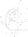
图1为一实施例的胫骨托假体组的各型号的胫骨托假体的对比示意图;Fig. 1 is the comparative schematic diagram of the tibial tray prosthesis of each model of the tibial tray prosthesis group of an embodiment;
图2为图1中所示的胫骨托假体组中的某一型号的胫骨托假体的后视图;Fig. 2 is the rear view of the tibial tray prosthesis of a certain model in the tibial tray prosthesis group shown in Fig. 1;
图3为图2中所示的胫骨托假体的俯视图;Figure 3 is a top view of the tibial tray prosthesis shown in Figure 2;
图4为一实施例的胫骨托假体组的各型号的胫骨托假体的对比示意图;Fig. 4 is the comparative schematic diagram of the tibial tray prosthesis of each model of the tibial tray prosthesis group of an embodiment;
图5为一实施例的胫骨托假体系列中各型号胫骨托假体的结构参数示例表;5 is an example table of structural parameters of various types of tibial tray prostheses in the tibial tray prosthesis series of an embodiment;
图6为传统的胫骨托假体系列中各型号胫骨托假体的结构参数示例表;Figure 6 is an example table of the structural parameters of various types of tibial tray prostheses in the traditional tibial tray prosthesis series;
图7为本发明一实施例的胫骨托假体的立柱和龙骨与传统的胫骨托假体的立柱和龙骨的相对位置差的示意表;7 is a schematic diagram of the relative position difference between the post and the keel of the tibial tray prosthesis according to an embodiment of the present invention and the post and the keel of the traditional tibial tray prosthesis;
图8为另一实施例的胫骨托假体系列中各型号胫骨托假体的结构参数示例表;8 is an example table of structural parameters of various types of tibial tray prostheses in the tibial tray prosthesis series of another embodiment;
图9为本发明另一实施例的胫骨托假体的立柱和龙骨与传统的胫骨托假体的立柱和龙骨的相对位置差的示意表。9 is a schematic diagram showing the relative position difference between the post and the keel of the tibial tray prosthesis according to another embodiment of the present invention and the post and the keel of the traditional tibial tray prosthesis.
附图标记说明:Description of reference numbers:
10、远端面;11、第一立柱;12、第二立柱;13、龙骨;14、第一侧面;15、第二侧面;16、后缘直面;21、第一基准面;22、第二基准面;30、近端面;31、凹槽。10. Distal surface; 11. The first column; 12. The second column; 13. The keel; 14. The first side surface; 15. The second side surface; Two reference planes; 30, proximal surface; 31, groove.
具体实施方式Detailed ways
为使本发明的上述目的、特征和优点能够更加明显易懂,下面结合附图对本发明的具体实施方式做详细的说明。在下面的描述中阐述了很多具体细节以便于充分理解本发明。但是本发明能够以很多不同于在此描述的其它方式来实施,本领域技术人员可以在不违背本发明内涵的情况下做类似改进,因此本发明不受下面公开的具体实施例的限制。In order to make the above objects, features and advantages of the present invention more clearly understood, the specific embodiments of the present invention will be described in detail below with reference to the accompanying drawings. In the following description, numerous specific details are set forth in order to provide a thorough understanding of the present invention. However, the present invention can be implemented in many other ways different from those described herein, and those skilled in the art can make similar improvements without departing from the connotation of the present invention. Therefore, the present invention is not limited by the specific embodiments disclosed below.
为了更好地阐述本发明的技术方案,首先对各实施例中可能涉及的方位名称进行解释:In order to better illustrate the technical solutions of the present invention, firstly, the names of the positions that may be involved in each embodiment are explained:
矢状面:指从前后方向,将人体或假体分成左、右两部分的纵切面,其中,经过人体或假体正中的矢状面为正中矢状面。Sagittal plane: refers to the longitudinal section that divides the human body or prosthesis into left and right parts from the front-to-back direction, and the sagittal plane passing through the middle of the human body or prosthesis is the midsagittal plane.
冠状面:指从左右方向,将人体或假体分为前后两部分的纵切面,该面与矢状面垂直,其中,经过人体或假体正中的冠状面为正中冠状面。Coronal plane: refers to the longitudinal section that divides the human body or prosthesis into front and rear parts from the left and right directions, and this plane is perpendicular to the sagittal plane.
横断面:也称水平面,是与地平面平行将人体或假体分为上、下两部分的平面,该平面与冠状面和矢状面相互垂直。Transverse plane: also known as the horizontal plane, is a plane parallel to the ground plane that divides the human body or prosthesis into upper and lower parts, and this plane is perpendicular to the coronal and sagittal planes.
内侧:相对接近人体正中矢状面的一侧。Medial: The side relatively close to the midsagittal plane of the human body.
外侧:相对远离人体正中矢状面的一侧。Lateral: The side relatively far from the midsagittal plane of the human body.
前侧:矢状面上相对接近腹部的一侧。Anterior: The side of the sagittal plane that is relatively close to the abdomen.
后侧:矢状面上相对接近背部的一侧。Posterior: The side relatively close to the back in the sagittal plane.
参阅图1,图1示出了本发明一实施例的胫骨托假体组中的各型号的胫骨托假体的对比示意图。具体地,参见图1-2,本发明一实施例的胫骨托假体组包括不同型号的至少两个胫骨托假体,每个胫骨托假体均包括远端面10,胫骨托假体的远端面10用于与患者截骨后形成的胫骨近端面30相配合,胫骨托假体的远端面10设有用于与胫骨连接的立柱以及龙骨13,立柱以及龙骨13于辅助胫骨托假体的固定。胫骨托假体还包括相对的第一侧面14以及第二侧面15,其中第一侧面14为直面,第二侧面15为曲面,对于用以置换膝关节的内侧间室的胫骨托假体来说第一侧面14即为胫骨托假体的外侧边缘,第二侧面15即为胫骨托假体的内侧边缘;相反地,对于用以置换膝关节的外侧间室的胫骨托假体来说第一侧面14即为胫骨托假体的内侧边缘,第二侧面15即为胫骨托假体的外侧边缘。胫骨托假体在第一侧面14的延伸方向上的最大长度即为胫骨托假体的前后径A。即,假设一条与第一侧面14的延伸方向垂直的直线与胫骨托假体的前端相切(称为前端切线),一条与第一侧面14的延伸方向垂直的直线与胫骨托假体的后端相切(称为后端切线),则前端切线与后端切线间的垂直距离即为胫骨托假体的前后径A。进一步地,在与第一侧面14的延伸方向垂直的方向上,胫骨托假体的最大宽度即为即为胫骨托假体的左右径B。即,第二侧面15上最远离第一侧面14的一点到第一侧面14的垂直距离即为胫骨托假体的左右径B。进一步地,不同型号的胫骨托假体即指的是前后径A以及左右径B均不相同的两个或两个以上的胫骨托假体。本发明所述的“直面”或“直线”并非数学意义上的直面或直线,而是指工程意义上的满足一定误差要求的直面或直线。另外可以理解的是,上述针对第一侧面14、第二侧面15的几何特征的描述,是基于其在水平面上的投影(图1),下述对第一基准面21以及第二基准面22的描述亦然。Referring to FIG. 1 , FIG. 1 shows a schematic diagram of comparison of various types of tibial tray prostheses in the tibial tray prosthesis group according to an embodiment of the present invention. 1-2, the tibial tray prosthesis set according to an embodiment of the present invention includes at least two tibial tray prostheses of different sizes, each tibial tray prosthesis includes a
进一步地,如图1所示,每个胫骨托假体还均设有第一基准面21以及第二基准面22,第二基准面22与第一基准面21相交,例如第二基准面22与第一基准面21相垂直设置。当不同型号的胫骨托假体的第一基准面21对齐并且第二基准面22对齐时,不同型号的胫骨托假体的立柱重合并且龙骨13重合,换而言之,在同一个胫骨托假体组内,无论胫骨托假体的前后径A以及左右径B增大还是减小,胫骨托假体的立柱与龙骨13相对于第一基准面21以及第二基准面22的位置均不改变。Further, as shown in FIG. 1 , each tibial tray prosthesis is further provided with a
具体地,传统的胫骨托假体的立柱和龙骨13位置随胫骨托假体的型号变化而变化,这主要是考虑胫骨托假体固定稳定性问题,理论上来说,立柱和龙骨13相对间距越大,固定稳定越好,因此传统胫骨托假体立柱和龙骨13的距离随型号的增大而增大。然而,我司研发人员通过有限元分析惊讶地发现,对于同一规格的胫骨托假体,立柱与龙骨13间距在一定范围内变化时,胫骨托固定稳定性并无显著差异,因此,上述胫骨托假体组通过保证在不同型号的胫骨托假体的第一基准面21相互对齐并且第二基准面22相互对齐时,不同型号的胫骨托假体的立柱和龙骨13均能重合,即保证了骨托假体的立柱与龙骨13相对于第一基准面21以及第二基准面22的位置不随胫骨托假体的尺寸改变而变化,从而在更替不同型号的胫骨托假体时无需对患者的胫骨截骨面进行重新开立柱孔以及龙骨槽等处理,从而避免了原本已经存在的立柱孔和龙骨槽破坏新立柱孔和龙骨槽的完整性的问题,提高了胫骨托假体的固定稳定性,减小胫骨托假体松动发生概率。同时无需重新开立柱孔以及龙骨槽也提高了手术操作效率,缩短了手术时间,降低了患者感染的发生概率。Specifically, the position of the post and the
进一步地,参见图1,在同一胫骨托假体组内,不同型号的胫骨托假体的左右径B随胫骨托假体的前后径A增大而增大,并且不同型号的胫骨托假体的立柱与龙骨13的间距D1保持第一定值,不同型号的胫骨托假体的立柱与第一基准面21的间距G1保持第二定值,不同型号的胫骨托假体的立柱到第二基准面22的间距保持第三定值。其中,立柱与龙骨13的间距D1指的是从水平面上看立柱的中心到龙骨13的几何中心的距离。而立柱与第一基准面21的间距指的是立柱的中心到第一基准面21的垂直距离,同理,立柱与第二基准面22的间距指的是立柱的中心到第二基准面22的垂直距离,通过使不同型号的胫骨托假体的立柱与龙骨13的间距D1、立柱与第一基准面21的间距G1以及立柱到第二基准面22的间距均保持定值,从而实现当不同型号的胫骨托假体的第一基准面21对齐并且第二基准面22对齐时,使不同型号的胫骨托假体的立柱与龙骨13均重合。Further, referring to Fig. 1, in the same tibial tray prosthesis group, the left and right diameter B of the tibial tray prosthesis of different models increases with the increase of the anterior and posterior diameters A of the tibial tray prosthesis, and the tibial tray prosthesis of different models increases. The distance D1 between the column and the
进一步地,参见图1,每个胫骨托假体均设有至少两个立柱,并且不同型号的胫骨托假体上相邻两个立柱之间的间距保持第四定值。例如图1所示,胫骨托假体设有第一立柱11以及第二立柱12,在同一组胫骨托假体组内的胫骨托假体的第一立柱11与第二立柱之间的间距C1不随胫骨托假体的前后径A以及左右径B的变化而变化。第一立柱11与第二立柱12之间的间距C1保持定值,第一立柱11到第一基准面21的间距G1保持定值,且第一立柱11和第二立柱12到第二基准面22的间距E1、F1均保持定值,从而保证各个立柱的相对位置固定,进而避免替不同型号的胫骨托假体时对患者的胫骨截骨面进行重新开立柱孔。需要说明的是,胫骨托假体上的立柱不限于上述实施例中的两个,还可以是三个,四个或更多,从而提高胫骨托假体的稳固性。Further, referring to FIG. 1 , each tibial tray prosthesis is provided with at least two uprights, and the distance between two adjacent uprights on different types of tibial tray prostheses maintains a fourth fixed value. For example, as shown in FIG. 1 , the tibial tray prosthesis is provided with a
具体地,参见图1,第一基准面21与第一侧面14相重合,即胫骨托假体以第一侧面14作为第一基准面21,由于第一侧面14为直面,以第一侧面14为第一基准面21更便于胫骨托假体组的参数设计。且在术中更换不同型号的胫骨托假体时,能以第一侧面14作为安装基准,更便于手术操作。Specifically, referring to FIG. 1 , the
进一步地,胫骨托假体还包括与第一侧面14垂直的后缘直面16,可以理解的是,后缘直面16与胫骨托假体的后端切线重合。在其中一个实施例中,胫骨托假体以后缘直面16作为第二基准面22,通过将后缘直面16作为第二基准面22,在进行相邻型号的胫骨托假体更换时,无论如何更换,都能保证胫骨托假体对胫骨后侧皮质的覆盖,胫骨后侧区域是膝关节活动过程中的主要承重区域,保证胫骨后侧皮质骨的覆盖能有效提高胫骨托假体的固定稳定性。进一步地,将后缘直面16作为第二基准面22,还能使立柱到后缘直面16的距离保持为定值,例如图1中所示第一立柱11到后缘直面16的距离E1为第五定值,第二立柱12到后缘直面16的距离F1为第六定值。在另一些实施例中,胫骨托假体也可以不包括后缘直面16,即胫骨托假体的后端全部为弧线,此时第二基准面22与胫骨托假体的后端切线重合,即,以垂直于第一侧面14的延伸方向且与胫骨托假体的后端相切的直线为第二基准面22。Further, the tibial tray prosthesis further includes a rear edge
进一步地,参见图4,在另一个实施例中,胫骨托假体可以以胫骨托假体的正中冠状面作为第二基准面22,即第二基准面22与胫骨托假体的正中冠状面重合,其中,胫骨托假体的正中冠状面为经过胫骨托假体的前后中心线的冠状面,即正中冠状面到胫骨托假体的前端切线和到胫骨托假体的后端切线的垂直距离相等。进一步地,当以胫骨托假体的正中冠状面作为第二基准面22时,立柱到第二基准面22的间距依旧保持定值,但立柱到后缘直面16或后端切线的间距随胫骨托假体的前后径增大而增大,并且相邻型号的胫骨托假体的立柱到后缘直面16的间距的变化量为前后径A的变化量的一半。需要说明的是,第一基准面21和第二基准面22的选择与假体安装方法有关,不限于上文所举实施例,可根据情况自主选择。例如,第一基准面21也可以与假体的正中矢状面重合等等。Further, referring to FIG. 4 , in another embodiment, the tibial tray prosthesis may use the median coronal plane of the tibial tray prosthesis as the
进一步地,本申请一实施例还提供一种胫骨托假体系列,具体地,胫骨托假体系列包括至少两组如上任一实施例的胫骨托假体组,不同组的胫骨托假体的左右径B随胫骨托假体的前后径A增大而增大,不同组的胫骨托假体的立柱与龙骨13的间距随胫骨托假体的前后径增大而增大,不同组的胫骨托假体的立柱与第一基准面21的间距随胫骨托假体的前后径A增大而增大。不同组的胫骨托假体的立柱与第二基准面22的间距随胫骨托假体的前后径A增大而增大。Further, an embodiment of the present application also provides a tibial tray prosthesis series, specifically, the tibial tray prosthesis series includes at least two groups of tibial tray prosthesis groups as described in any of the above embodiments, and different groups of tibial tray prosthesis groups. The left and right diameter B increases with the increase of the anteroposterior diameter A of the tibial tray prosthesis. The distance between the post and the
具体地,参见图5,图5为本发明一实施例的胫骨托假体系列中各型号胫骨托假体的结构参数示例表,在本实施例中,每个胫骨托假体均以第一侧面14作为第一基准面21,并以后缘直面16作为第二基准面22。并且每个胫骨托假体均设有两个立柱,分别为第一立柱11以及第二立柱12。其中胫骨托假体的结构参数包括前后径A、左右径B、第一立柱11与第二立柱12的间距C1、第二立柱12与龙骨13的间距D1、第一立柱11到后缘直面16(即第二基准面22)的距离E1、第二立柱12与后缘直面16(即第二基准面22)的距离F1以及第一立柱11与第一侧面14(即第一基准面21)的距离G1。Specifically, referring to FIG. 5 , FIG. 5 is an example table of the structural parameters of each type of tibial tray prosthesis in the tibial tray prosthesis series according to an embodiment of the present invention. In this embodiment, each tibial tray prosthesis uses the first The
具体地,如图5所示,胫骨托假体系列包括四组胫骨托假体组,每组胫骨托假体组均包括三个相邻型号的胫骨托假体,在同一组胫骨托假体组内,不同型号的胫骨托假体的左右径B随胫骨托假体的前后径A增大而增大,但不同型号的胫骨托假体的第一立柱11与第二立柱12的间距C1、第二立柱12与龙骨13的间距D1、第一立柱11到后缘直面16的距离E1、第二立柱12与后缘直面16的距离F1以及第一立柱11与第一侧面14的距离G1均保持不变,从而当同一组胫骨托假体组内的不同型号的胫骨托假体的第一基准面21对齐并且第二基准面22对齐时,使胫骨托假体的第一立柱11、第二立柱12以及龙骨13均能完全重合,进而实现在术中同组胫骨托假体的互换,而无需对胫骨截骨面重新进行处理。Specifically, as shown in FIG. 5 , the tibial tray prosthesis series includes four sets of tibial tray prosthesis groups, and each tibial tray prosthesis group includes three adjacent models of tibial tray prostheses. In the group, the left and right diameters B of different types of tibial tray prostheses increase with the increase of the anterior and posterior diameters A of the tibial tray prostheses, but the distance C1 between the
进一步地,继续参见图5,不同组的胫骨托假体的左右径B随胫骨托假体的前后径A增大而增大,并且不同组的胫骨托假体的的第一立柱11与第二立柱12的间距C1、第二立柱12与龙骨13的间距D1、第一立柱11到后缘直面16的距离E1、第二立柱12与后缘直面16的距离F1以及第一立柱11与第一侧面14的距离G1均随胫骨托假体的前后径A增大而增大,例如在其中一个实施例中,1-4组中各组的胫骨托假体的第一立柱11与第二立柱12的间距C1分别为11.9mm、14.1mm、16.0mm、17.8mm,增大,其他参数同理,在此不做赘述。Further, continuing to refer to FIG. 5 , the left and right diameters B of the tibial tray prostheses of different groups increase with the increase of the anterior and posterior diameters A of the tibial tray prostheses, and the
当一个胫骨托假体系列包含有较多型号的胫骨托假体,且胫骨托假体的尺寸跨度较大时,如若所有型号的胫骨托假体均采用相同的第一立柱11与第二立柱12的间距C1、第二立柱12与龙骨13的间距D1、第一立柱11到后缘直面16的距离E1、第二立柱12与后缘直面16的距离F1以及第一立柱11与第一侧面14的距离G1可能会导致最小号的胫骨托假体或最大号的胫骨托假体的稳定性得不到保障。此外医生在进行更换胫骨托假体型号时,通常只是更换相邻型号的胫骨托假体,因此,本发明的胫骨托假体系列通过将型号尺寸跨度较大的多个胫骨托假体分为至少两个胫骨托假体组,将一定范围内的相邻型号的胫骨托假体作为一组胫骨托假体组,在同一组胫骨托假体组内,将不同型号的胫骨托假体的第一立柱11与第二立柱12的间距C1、第二立柱12与龙骨13的间距D1、第一立柱11到后缘直面16的距离E1、第二立柱12与后缘直面16的距离F1以及第一立柱11与第一侧面14的距离G1均保持不变,从而实现在术中使同一组的胫骨托假体能互换,且无需对胫骨截骨面重新进行处理,既实现了同一组的不同型号的胫骨托假体具有互换性,又保证了不同组内尺寸跨度较大的胫骨托假体的各自稳定性。When a tibial tray prosthesis series includes more types of tibial tray prostheses, and the size span of the tibial tray prosthesis is large, if all types of tibial tray prostheses use the same
进一步地,为了验证本发明的胫骨托假体系列的各型号的胫骨托假体的稳定性与传统的胫骨托假体的稳定性无明显差异性,我司研究人员还做了相关的有限元分析,具体地,参见图6以及图7,图6为传统的胫骨托假体系列的各型号胫骨托假体的结构参数示例表,图7为传统的胫骨托假体和本发明一实施例的胫骨托假体的立柱和龙骨13相对位置差示意表,从表中可看出型号1的相对位置差最大,因此分别对传统的型号1的胫骨托假体以及本实施例的型号1的胫骨托假体的稳定性进行有限元分析。Further, in order to verify that the stability of the tibial tray prosthesis of each model of the tibial tray prosthesis series of the present invention is not significantly different from the stability of the traditional tibial tray prosthesis, our researchers also performed the relevant finite element method. Analysis, specifically, referring to Fig. 6 and Fig. 7, Fig. 6 is an example table of the structural parameters of each type of tibial tray prosthesis of the traditional tibial tray prosthesis series, Fig. 7 is a traditional tibial tray prosthesis and an embodiment of the present invention The relative position difference between the column and the
具体地,稳定性分析包括剪切稳定性分析和旋转稳定性分析。剪切稳定性分析方法为模拟胫骨托假体用骨水泥固定到松质骨上,在胫骨托假体的几何中心施加1000N的前后方向的剪切力,计算胫骨托假体的水平位移。旋转稳定性分析方法为模拟胫骨托假体用骨水泥固定到松质骨上,在胫骨托假体几何中心施加内外方向5Nm的扭矩,计算胫骨托假体的旋转位移。经过有限元分析,分析结果如下:在1000N的水平方向剪切力作用下,传统的型号1胫骨托假体的最大平动位移为79.98微米,在5Nm的旋转扭转作用下,传统的型号1胫骨托假体的最大旋转位移为17.07微米。在同样的水平剪切力及旋转扭矩作用下,按本发明的型号1胫骨托假体的最大平动位移和旋转位移分别为78.28微米和17.27微米,分析结果表明,两种不同设计方案的胫骨托假体稳定性并无显著性差异。Specifically, the stability analysis includes shear stability analysis and rotational stability analysis. The shear stability analysis method is to simulate the tibial tray prosthesis fixed on the cancellous bone with bone cement, and apply a shear force of 1000N in the anterior and posterior directions at the geometric center of the tibial tray prosthesis to calculate the horizontal displacement of the tibial tray prosthesis. The rotational stability analysis method is to simulate the tibial tray prosthesis fixed on the cancellous bone with bone cement, apply a torque of 5 Nm in the internal and external directions at the geometric center of the tibial tray prosthesis, and calculate the rotational displacement of the tibial tray prosthesis. After finite element analysis, the analysis results are as follows: under the horizontal shear force of 1000N, the maximum translational displacement of the
进一步,参见图8,图8为本发明另一实施例的胫骨托假体系列中各胫骨托假体的结构参数示例表,在本实施例中,每个胫骨托假体均以第一侧面14作为第一基准面21,以后胫骨托假体的正中冠状面作为第二基准面22。并且每个胫骨托假体均设有两个立柱,分别为第一立柱11以及第二立柱12。其中胫骨托假体的结构参数包括前后径A、左右径B、第一立柱11与第二立柱12的间距C2、第二立柱12与龙骨13的间距D2、第一立柱11到后缘直面16的距离E2、第二立柱12与后缘直面16的距离F2以及第一立柱11与第一侧面14(即第一基准面21)的距离G2。Further, referring to FIG. 8 , FIG. 8 is an example table of structural parameters of each tibial tray prosthesis in the tibial tray prosthesis series according to another embodiment of the present invention. In this embodiment, each tibial tray prosthesis has a first side surface. 14 is used as the
具体地,如图8所示,胫骨托假体系列包括四组胫骨托假体组,每组胫骨托假体组均包括三个相邻型号的胫骨托假体,在同一组胫骨托假体组内,不同型号的胫骨托假体的左右径B随胫骨托假体的前后径A增大而增大,第一立柱11到后缘直面16的距离E2以及第二立柱12与后缘直面16的距离F2随胫骨托假体的前后径A增大而增大,并且E2以及F2的变化量为前后径A的变化量的一半。但不同型号的胫骨托假体的第一立柱11与第二立柱12的间距C2、第二立柱12与龙骨13的间距D2以及第一立柱11与第一侧面14的距离G2均保持不变,从而当同一组胫骨托假体组内的不同型号的胫骨托假体的第一基准面21对齐并且第二基准面22对齐时,胫骨托假体的第一立柱11、第二立柱12以及龙骨13均能完全重合,进而实现在术中同组胫骨托假体的互换,而无需对胫骨截骨面重新进行处理。Specifically, as shown in FIG. 8 , the tibial tray prosthesis series includes four groups of tibial tray prostheses, and each tibial tray prosthesis group includes three adjacent models of tibial tray prostheses. In the same set of tibial tray prostheses Within the group, the left and right diameters B of different types of tibial tray prostheses increase with the increase of the anterior and posterior diameters A of the tibial tray prosthesis, the distance E2 from the
进一步地,继续参见图8,不同组的胫骨托假体的左右径B随胫骨托假体的前后径A增大而增大,并且不同组的胫骨托假体的的第一立柱11与第二立柱12的间距C2、第二立柱12与龙骨13的间距D2、第一立柱11到后缘直面16的距离E2、第二立柱12与后缘直面16的距离F2以及第一立柱11与第一侧面14的距离G2均随胫骨托假体的前后径A增大而增大,例如表中所示,1-4组中各组的胫骨托假体的第一立柱11与第二立柱12的间距C2分别为11.9mm、14.1mm、16.0mm、17.8mm,增大,其他参数同理,在此不做赘述。Further, continuing to refer to FIG. 8 , the left and right diameters B of the tibial tray prostheses of different groups increase with the increase of the anterior and posterior diameters A of the tibial tray prostheses, and the
同样对本实施例的的胫骨托假体系列中各型号的胫骨托假体进行稳定性分析。具体地,参见图9,图9为传统的胫骨托假体和本发明另一实施例的胫骨托假体的立柱和龙骨13的相对位置差示意表。从表中可看出,型号1的胫骨托假体的立柱以及龙骨13的相对位置差最大,并且该相对位置差小于图7中的型号1的胫骨托假体的立柱以及龙骨13的相对位置差,由此可合理推断这样的相对位置差也不会对胫骨托假体稳定性造成影响。The stability analysis is also performed on each type of tibial tray prosthesis in the tibial tray prosthesis series of this embodiment. Specifically, referring to FIG. 9 , FIG. 9 is a schematic diagram showing the relative position difference between the post and the
上述胫骨托假体系列将型号尺寸跨度较大的多个胫骨托假体分为至少两个胫骨托假体组,将一定范围内的相邻型号的胫骨托假体作为一组胫骨托假体组,在同一组胫骨托假体组内的胫骨托假体的第一基准面21相互对齐并且第二基准面22相互对齐时,不同型号的胫骨托假体的立柱和龙骨13均能重合,从而实现在术中更换同一组不同型号的胫骨托假体时无需对胫骨截骨面重新进行处理,既实现了同一组的不同型号的胫骨托假体具有互换性,又保证了不同组内尺寸跨度较大的胫骨托假体的各自稳定性。The above-mentioned tibial tray prosthesis series divides multiple tibial tray prostheses with a large size span into at least two tibial tray prosthesis groups, and uses adjacent models of tibial tray prostheses within a certain range as a group of tibial tray prostheses group, when the
需要说明的是,胫骨托假体系列包含的胫骨托假体组的组数不限于上述四组,可根据实际需求增加或减少胫骨托假体组的组数。并且每组胫骨托假体组内所包含的胫骨托假体的数量也不限于三个。例如在另外的实施例中,胫骨托假体系列可包括12组胫骨托假体组,每个胫骨托假体组又包含大、中、小三个型号的胫骨托假体,其中,12组胫骨托假体组内中型号的胫骨托假体的结构参数分别参照图6中传统的胫骨托假1-12号胫骨托假体的结构参数设计。而各组的大号与小号的胫骨托假体的结构参数除了前后径A以及左右径B有所增减外,其余胫骨托假体的立柱与龙骨13的间距D、立柱与第一基准面21的间距E、立柱到第二基准面22的间距均保持不变,如此对于传统的12种型号的胫骨托假体均有对应的大一号或小一号的胫骨托假体能与之互换,且无需对胫骨的截骨面进行重新处理。It should be noted that the number of tibial tray prosthesis groups included in the tibial tray prosthesis series is not limited to the above four groups, and the number of tibial tray prosthesis groups may be increased or decreased according to actual needs. In addition, the number of tibial tray prostheses included in each tibial tray prosthesis group is not limited to three. For example, in another embodiment, the tibial tray prosthesis series may include 12 groups of tibial tray prostheses, and each tibial tray prosthesis group further includes three models of large, medium and small tibial tray prostheses, wherein the 12 groups of tibial trays The structural parameters of the middle-sized tibial tray prosthesis in the tibial tray prosthesis group are designed with reference to the structural parameters of the traditional tibial tray prosthesis Nos. 1-12 in FIG. 6 . For the large and small tibial tray prostheses in each group, except for the anterior-posterior diameter A and the left-right diameter B, the structural parameters of the other tibial tray prostheses were increased or decreased, the distance D between the post and the
进一步地,本申请一实施例还提供一种胫骨假体,胫骨假体包括上述任一实施例的胫骨托假体系列以及用于与胫骨托假体相配合的胫骨衬垫。进一步地,参见图3,每一个胫骨托假体均具有与远端面10相对的近端面30,近端面30上设有用于与胫骨衬垫相配合的配合部,配合部依据不同类型的单髁假体具有不同的特征,如对于活动平台单髁假体,胫骨托假体的配合部为光滑平面,胫骨托假体与胫骨衬垫间无机械连接,使得胫骨衬垫能在胫骨托假体的近端面30上自由运动。而对于固定平台单髁假体,胫骨托假体的配合部为凹槽31,凹槽31的边缘设有凸缘,凹槽31的凸缘通过卡扣连接方式与胫骨衬垫进行锁合,保证胫骨衬垫2与胫骨托假体的锁定稳定性。需要说明的是,只要能保证与胫骨衬垫的卡扣连接可靠性,凹槽31可以采用任何形状,如梯形、矩形或其它类型的不规则形状等。Further, an embodiment of the present application further provides a tibial prosthesis, which includes the tibial tray prosthesis series of any of the above embodiments and a tibial pad for matching with the tibial tray prosthesis. Further, referring to FIG. 3 , each tibial tray prosthesis has a
上述胫骨假体采用了前述的胫骨托假体系列,胫骨托假体系列将型号尺寸跨度较大的多个胫骨托假体分为至少两个胫骨托假体组,将一定范围内的相邻型号的胫骨托假体作为一组胫骨托假体组,并且保证在同一组胫骨托假体组内的胫骨托假体的第一基准面21相互对齐并且第二基准面22相互对齐时,不同型号的胫骨托假体的立柱和龙骨13均能重合,从而实现在术中更换同一组不同型号的胫骨托假体时无需对胫骨截骨面重新进行处理,提高了胫骨托假体的固定稳定性,减小胫骨托假体松动发生概率。同时提高了手术操作效率,减小了手术时间,降低了患者感染的发生概率。The above-mentioned tibial prosthesis adopts the aforementioned tibial tray prosthesis series. The tibial tray prosthesis series divides a plurality of tibial tray prostheses with large model and size span into at least two tibial tray prosthesis groups, and separates adjacent tibial tray prostheses within a certain range. The tibial tray prosthesis of the model is used as a set of tibial tray prostheses, and it is ensured that the
进一步地,本申请一实施例还提供一种膝关节系统,具体地,膝关节系统包括上述任一实施例的胫骨假体以及股骨假体。其中胫骨假体又包括胫骨托假体以及胫骨衬垫,股骨假体用于置换股骨远端病变骨组织,胫骨托假体用于置换胫骨近端病变骨组织,胫骨衬垫用于替换半月板以达到降低摩擦磨损的目的。Further, an embodiment of the present application further provides a knee joint system, specifically, the knee joint system includes the tibial prosthesis and the femoral prosthesis according to any of the foregoing embodiments. The tibial prosthesis includes a tibial tray prosthesis and a tibial pad. The femoral prosthesis is used to replace the diseased bone tissue of the distal femur, the tibial tray prosthesis is used to replace the diseased bone tissue of the proximal tibia, and the tibial pad is used to replace the meniscus. In order to achieve the purpose of reducing friction and wear.
上述膝关节系统采用了前述的胫骨托假体系列,胫骨托假体系列将型号尺寸跨度较大的多个胫骨托假体分为至少两个胫骨托假体组,将一定范围内的相邻型号的胫骨托假体作为一组胫骨托假体组,并且保证在同一组胫骨托假体组内的胫骨托假体的第一基准面21相互对齐并且第二基准面22相互对齐时,不同型号的胫骨托假体的立柱和龙骨13均能重合,从而实现在术中更换同一组不同型号的胫骨托假体时无需对胫骨截骨面重新进行处理,提高了胫骨托假体的固定稳定性,减小胫骨托假体松动发生概率。同时提高了手术操作效率,减小了手术时间,降低了患者感染的发生概率。The above knee joint system adopts the aforementioned tibial tray prosthesis series. The tibial tray prosthesis series divides multiple tibial tray prostheses with large size spans into at least two tibial tray prosthesis groups, and separates adjacent tibial tray prostheses within a certain range. The tibial tray prosthesis of the model is used as a set of tibial tray prostheses, and it is ensured that the
以上所述实施例的各技术特征可以进行任意的组合,为使描述简洁,未对上述实施例中的各个技术特征所有可能的组合都进行描述,然而,只要这些技术特征的组合不存在矛盾,都应当认为是本说明书记载的范围。The technical features of the above-described embodiments can be combined arbitrarily. For the sake of brevity, all possible combinations of the technical features in the above-described embodiments are not described. However, as long as there is no contradiction between the combinations of these technical features, All should be regarded as the scope described in this specification.
以上所述实施例仅表达了本发明的几种实施方式,其描述较为具体和详细,但并不能因此而理解为对发明专利范围的限制。应当指出的是,对于本领域的普通技术人员来说,在不脱离本发明构思的前提下,还可以做出若干变形和改进,这些都属于本发明的保护范围。因此,本发明专利的保护范围应以所附权利要求为准。The above-mentioned embodiments only represent several embodiments of the present invention, and the descriptions thereof are more specific and detailed, but should not be construed as a limitation on the scope of the invention patent. It should be pointed out that for those of ordinary skill in the art, without departing from the concept of the present invention, several modifications and improvements can also be made, which all belong to the protection scope of the present invention. Therefore, the protection scope of the patent of the present invention shall be subject to the appended claims.
在本发明的描述中,需要理解的是,术语“中心”、“纵向”、“横向”、“长度”、“宽度”、“厚度”、“上”、“下”、“前”、“后”、“左”、“右”、“竖直”、“水平”、“顶”、“底”、“内”、“外”、“顺时针”、“逆时针”、“轴向”、“径向”、“周向”等指示的方位或位置关系为基于附图所示的方位或位置关系,仅是为了便于描述本发明和简化描述,而不是指示或暗示所指的装置或元件必须具有特定的方位、以特定的方位构造和操作,因此不能理解为对本发明的限制。In the description of the present invention, it should be understood that the terms "center", "longitudinal", "lateral", "length", "width", "thickness", "upper", "lower", "front", " Back, Left, Right, Vertical, Horizontal, Top, Bottom, Inner, Outer, Clockwise, Counterclockwise, Axial , "radial", "circumferential" and other indicated orientations or positional relationships are based on the orientations or positional relationships shown in the accompanying drawings, and are only for the convenience of describing the present invention and simplifying the description, rather than indicating or implying the indicated device or Elements must have a particular orientation, be constructed and operate in a particular orientation and are therefore not to be construed as limitations of the invention.
此外,术语“第一”、“第二”仅用于描述目的,而不能理解为指示或暗示相对重要性或者隐含指明所指示的技术特征的数量。由此,限定有“第一”、“第二”的特征可以明示或者隐含地包括至少一个该特征。在本发明的描述中,“多个”的含义是至少两个,例如两个,三个等,除非另有明确具体的限定。In addition, the terms "first" and "second" are only used for descriptive purposes, and should not be construed as indicating or implying relative importance or implying the number of indicated technical features. Thus, a feature delimited with "first", "second" may expressly or implicitly include at least one of that feature. In the description of the present invention, "plurality" means at least two, such as two, three, etc., unless otherwise expressly and specifically defined.
在本发明中,除非另有明确的规定和限定,术语“安装”、“相连”、“连接”、“固定”等术语应做广义理解,例如,可以是固定连接,也可以是可拆卸连接,或成一体;可以是机械连接,也可以是电连接;可以是直接相连,也可以通过中间媒介间接相连,可以是两个元件内部的连通或两个元件的相互作用关系,除非另有明确的限定。对于本领域的普通技术人员而言,可以根据具体情况理解上述术语在本发明中的具体含义。In the present invention, unless otherwise expressly specified and limited, the terms "installed", "connected", "connected", "fixed" and other terms should be understood in a broad sense, for example, it may be a fixed connection or a detachable connection , or integrated; it can be a mechanical connection or an electrical connection; it can be directly connected or indirectly connected through an intermediate medium, it can be the internal connection of two elements or the interaction relationship between the two elements, unless otherwise specified limit. For those of ordinary skill in the art, the specific meanings of the above terms in the present invention can be understood according to specific situations.
在本发明中,除非另有明确的规定和限定,第一特征在第二特征“上”或“下”可以是第一和第二特征直接接触,或第一和第二特征通过中间媒介间接接触。而且,第一特征在第二特征“之上”、“上方”和“上面”可是第一特征在第二特征正上方或斜上方,或仅仅表示第一特征水平高度高于第二特征。第一特征在第二特征“之下”、“下方”和“下面”可以是第一特征在第二特征正下方或斜下方,或仅仅表示第一特征水平高度小于第二特征。In the present invention, unless otherwise expressly specified and limited, a first feature "on" or "under" a second feature may be in direct contact between the first and second features, or the first and second features indirectly through an intermediary touch. Also, the first feature being "above", "over" and "above" the second feature may mean that the first feature is directly above or obliquely above the second feature, or simply means that the first feature is level higher than the second feature. The first feature being "below", "below" and "below" the second feature may mean that the first feature is directly below or obliquely below the second feature, or simply means that the first feature has a lower level than the second feature.
需要说明的是,当元件被称为“固定于”或“设置于”另一个元件,它可以直接在另一个元件上或者也可以存在居中的元件。当一个元件被认为是“连接”另一个元件,它可以是直接连接到另一个元件或者可能同时存在居中元件。本文所使用的术语“垂直的”、“水平的”、“上”、“下”、“左”、“右”以及类似的表述只是为了说明的目的,并不表示是唯一的实施方式。It should be noted that when an element is referred to as being "fixed to" or "disposed on" another element, it can be directly on the other element or an intervening element may also be present. When an element is referred to as being "connected" to another element, it can be directly connected to the other element or intervening elements may also be present. The terms "vertical", "horizontal", "upper", "lower", "left", "right" and similar expressions used herein are for the purpose of illustration only and do not represent the only embodiment.
Claims (11)
Priority Applications (2)
| Application Number | Priority Date | Filing Date | Title |
|---|---|---|---|
| CN202010502934.0ACN111772887A (en) | 2020-06-05 | 2020-06-05 | Knee joint system, tibial prosthesis, tibial tray prosthesis series and tibial tray prosthesis group |
| PCT/CN2021/087218WO2021244150A1 (en) | 2020-06-05 | 2021-04-14 | Knee joint system, tibial prosthesis, tibial tray prosthesis series, and tibial tray prosthesis group |
Applications Claiming Priority (1)
| Application Number | Priority Date | Filing Date | Title |
|---|---|---|---|
| CN202010502934.0ACN111772887A (en) | 2020-06-05 | 2020-06-05 | Knee joint system, tibial prosthesis, tibial tray prosthesis series and tibial tray prosthesis group |
Publications (1)
| Publication Number | Publication Date |
|---|---|
| CN111772887Atrue CN111772887A (en) | 2020-10-16 |
Family
ID=72754623
Family Applications (1)
| Application Number | Title | Priority Date | Filing Date |
|---|---|---|---|
| CN202010502934.0APendingCN111772887A (en) | 2020-06-05 | 2020-06-05 | Knee joint system, tibial prosthesis, tibial tray prosthesis series and tibial tray prosthesis group |
Country Status (2)
| Country | Link |
|---|---|
| CN (1) | CN111772887A (en) |
| WO (1) | WO2021244150A1 (en) |
Cited By (1)
| Publication number | Priority date | Publication date | Assignee | Title |
|---|---|---|---|---|
| WO2021244150A1 (en)* | 2020-06-05 | 2021-12-09 | 苏州微创关节医疗科技有限公司 | Knee joint system, tibial prosthesis, tibial tray prosthesis series, and tibial tray prosthesis group |
Citations (12)
| Publication number | Priority date | Publication date | Assignee | Title |
|---|---|---|---|---|
| US5330534A (en)* | 1992-02-10 | 1994-07-19 | Biomet, Inc. | Knee joint prosthesis with interchangeable components |
| CN1137882A (en)* | 1994-12-30 | 1996-12-18 | Jbs有限公司 | Knee joint artificial limb |
| US6165223A (en)* | 1999-03-01 | 2000-12-26 | Biomet, Inc. | Floating bearing knee joint prosthesis with a fixed tibial post |
| CN102058448A (en)* | 2009-11-17 | 2011-05-18 | 德普伊产品公司 | Fixed bearing knee prosthesis with interchangeable components |
| US20120185055A1 (en)* | 2011-01-19 | 2012-07-19 | Wright Medical Technology, Inc. | Knee implant system |
| CN103153237A (en)* | 2010-07-24 | 2013-06-12 | 捷迈有限公司 | Asymmetric tibial components for a knee prosthesis |
| WO2013135361A1 (en)* | 2012-03-12 | 2013-09-19 | Montanaro Daniele | Device for bone cement application, particularly for arthroprosthesis implants |
| CN104027188A (en)* | 2013-03-07 | 2014-09-10 | 德普伊(爱尔兰)有限公司 | Fixed-bearing Knee Prosthesis Having Interchangeable Components |
| CN109077834A (en)* | 2018-09-29 | 2018-12-25 | 北京爱康宜诚医疗器材有限公司 | Tibial plateau prosthesis assembly |
| CN110664517A (en)* | 2019-08-27 | 2020-01-10 | 苏州微创关节医疗科技有限公司 | tibial tray prosthesis |
| CN110786969A (en)* | 2019-10-28 | 2020-02-14 | 北京市春立正达医疗器械股份有限公司 | Tibial plateau holds in palm and uses its unicondylar knee joint prosthesis |
| CN212438953U (en)* | 2020-06-05 | 2021-02-02 | 苏州微创关节医疗科技有限公司 | Knee joint system, tibial prosthesis, tibial tray prosthesis series and tibial tray prosthesis set |
Family Cites Families (5)
| Publication number | Priority date | Publication date | Assignee | Title |
|---|---|---|---|---|
| US5226915A (en)* | 1992-04-03 | 1993-07-13 | Bertin Kim C | Femoral prosthesis component system for knee replacement surgery |
| AU2002330660A1 (en)* | 2002-08-15 | 2004-03-03 | La Fondation De Soutien De L'hopital Orthopedique De La Suisse Romande | Knee prosthesis |
| US9144499B2 (en)* | 2013-12-17 | 2015-09-29 | Depuy (Ireland) | Low profile mobile/fixed prosthetic knee systems |
| FR3052353B1 (en)* | 2016-06-10 | 2020-02-28 | Pascal Marceaux | TIBIAL PART OF A KNEE PROSTHESIS, PARTICULARLY UNICOMPARTMENTAL, COMPRISING A TIBIAL TRAY. |
| CN111772887A (en)* | 2020-06-05 | 2020-10-16 | 苏州微创关节医疗科技有限公司 | Knee joint system, tibial prosthesis, tibial tray prosthesis series and tibial tray prosthesis group |
- 2020
- 2020-06-05CNCN202010502934.0Apatent/CN111772887A/enactivePending
- 2021
- 2021-04-14WOPCT/CN2021/087218patent/WO2021244150A1/ennot_activeCeased
Patent Citations (12)
| Publication number | Priority date | Publication date | Assignee | Title |
|---|---|---|---|---|
| US5330534A (en)* | 1992-02-10 | 1994-07-19 | Biomet, Inc. | Knee joint prosthesis with interchangeable components |
| CN1137882A (en)* | 1994-12-30 | 1996-12-18 | Jbs有限公司 | Knee joint artificial limb |
| US6165223A (en)* | 1999-03-01 | 2000-12-26 | Biomet, Inc. | Floating bearing knee joint prosthesis with a fixed tibial post |
| CN102058448A (en)* | 2009-11-17 | 2011-05-18 | 德普伊产品公司 | Fixed bearing knee prosthesis with interchangeable components |
| CN103153237A (en)* | 2010-07-24 | 2013-06-12 | 捷迈有限公司 | Asymmetric tibial components for a knee prosthesis |
| US20120185055A1 (en)* | 2011-01-19 | 2012-07-19 | Wright Medical Technology, Inc. | Knee implant system |
| WO2013135361A1 (en)* | 2012-03-12 | 2013-09-19 | Montanaro Daniele | Device for bone cement application, particularly for arthroprosthesis implants |
| CN104027188A (en)* | 2013-03-07 | 2014-09-10 | 德普伊(爱尔兰)有限公司 | Fixed-bearing Knee Prosthesis Having Interchangeable Components |
| CN109077834A (en)* | 2018-09-29 | 2018-12-25 | 北京爱康宜诚医疗器材有限公司 | Tibial plateau prosthesis assembly |
| CN110664517A (en)* | 2019-08-27 | 2020-01-10 | 苏州微创关节医疗科技有限公司 | tibial tray prosthesis |
| CN110786969A (en)* | 2019-10-28 | 2020-02-14 | 北京市春立正达医疗器械股份有限公司 | Tibial plateau holds in palm and uses its unicondylar knee joint prosthesis |
| CN212438953U (en)* | 2020-06-05 | 2021-02-02 | 苏州微创关节医疗科技有限公司 | Knee joint system, tibial prosthesis, tibial tray prosthesis series and tibial tray prosthesis set |
Cited By (1)
| Publication number | Priority date | Publication date | Assignee | Title |
|---|---|---|---|---|
| WO2021244150A1 (en)* | 2020-06-05 | 2021-12-09 | 苏州微创关节医疗科技有限公司 | Knee joint system, tibial prosthesis, tibial tray prosthesis series, and tibial tray prosthesis group |
Also Published As
| Publication number | Publication date |
|---|---|
| WO2021244150A1 (en) | 2021-12-09 |
Similar Documents
| Publication | Publication Date | Title |
|---|---|---|
| JP6563418B2 (en) | Dynamic registration and novel femoral prosthesis and tibial prosthesis | |
| US9317634B2 (en) | Surgical guide with cut resistant inserts | |
| US8852235B2 (en) | Posteriorly inserted artificial disc and an artificial facet joint | |
| US12263089B2 (en) | Artificial prosthesis for knee arthroplasty | |
| CN111467089A (en) | Interchangeable Unicondylar Femoral Prosthesis System and Knee Joint System | |
| WO2020155932A1 (en) | Unicondylar femoral prosthesis, tibia pad, and unicondylar replacement prosthesis | |
| CN107280817B (en) | Femoral lateral medial and lateral unicondylar prosthesis and femoral trochlear prosthesis | |
| CN110786969B (en) | Tibial plateau support and unicompartmental knee joint prosthesis using the same | |
| CN110638508A (en) | Customized patient-specific orthopaedic instruments | |
| CN107280818B (en) | Femoral-side prosthesis and tibial-side prosthesis for artificial knee replacement | |
| CN111772887A (en) | Knee joint system, tibial prosthesis, tibial tray prosthesis series and tibial tray prosthesis group | |
| US20120191211A1 (en) | Foot and ankle implant and associated method | |
| CN212438953U (en) | Knee joint system, tibial prosthesis, tibial tray prosthesis series and tibial tray prosthesis set | |
| CN109009576B (en) | Unicondylar knee prosthesis | |
| CN212438952U (en) | Tibial tray prosthesis | |
| CN109157309A (en) | Proximal tibia filling block prosthese | |
| CN212438950U (en) | Interchangeable type single-condyle femoral prosthesis system and knee joint system | |
| CN213156734U (en) | Unicondylar femoral prosthesis system and unicondylar femoral prosthesis | |
| CN216962561U (en) | Single condyle replacement operation cuts bone guide structure based on shin bone retroversion | |
| WO2021233025A1 (en) | Tibial tray prosthesis | |
| KR102359302B1 (en) | Patient-specific pin guide for total knee arthroplasty including an anatomical theory-based lower extremity alignment check part | |
| CN213665986U (en) | Artificial dentata prosthesis | |
| CN114939008A (en) | Femoral stem system and hip prosthesis | |
| CN112206080A (en) | An artificial axial prosthesis | |
| CN217488972U (en) | Subtotal artificial vertebral body |
Legal Events
| Date | Code | Title | Description |
|---|---|---|---|
| PB01 | Publication | ||
| PB01 | Publication | ||
| SE01 | Entry into force of request for substantive examination | ||
| SE01 | Entry into force of request for substantive examination |