CN111770881A - Remote Controlled Aviation Ordnance - Google Patents
Remote Controlled Aviation OrdnanceDownload PDFInfo
- Publication number
- CN111770881A CN111770881ACN201880064739.5ACN201880064739ACN111770881ACN 111770881 ACN111770881 ACN 111770881ACN 201880064739 ACN201880064739 ACN 201880064739ACN 111770881 ACN111770881 ACN 111770881A
- Authority
- CN
- China
- Prior art keywords
- ordnance
- target
- remote control
- blades
- control device
- Prior art date
- Legal status (The legal status is an assumption and is not a legal conclusion. Google has not performed a legal analysis and makes no representation as to the accuracy of the status listed.)
- Pending
Links
- 239000002360explosiveSubstances0.000claimsabstractdescription45
- 238000000034methodMethods0.000claimsdescription23
- 238000003384imaging methodMethods0.000claimsdescription12
- 230000007246mechanismEffects0.000claimsdescription7
- 239000000126substanceSubstances0.000claimsdescription6
- 230000005484gravityEffects0.000claimsdescription5
- 230000001141propulsive effectEffects0.000claimsdescription4
- 230000005540biological transmissionEffects0.000claimsdescription3
- BHEPBYXIRTUNPN-UHFFFAOYSA-Nhydridophosphorus(.) (triplet)Chemical compound[PH]BHEPBYXIRTUNPN-UHFFFAOYSA-N0.000claimsdescription3
- 230000004044responseEffects0.000claimsdescription3
- 239000003795chemical substances by applicationSubstances0.000claimsdescription2
- 230000000977initiatory effectEffects0.000claimsdescription2
- 230000000694effectsEffects0.000claims2
- 238000009527percussionMethods0.000claims1
- 239000000463materialSubstances0.000abstractdescription4
- 238000005286illuminationMethods0.000description11
- 238000001931thermographyMethods0.000description10
- 239000000523sampleSubstances0.000description8
- 230000008878couplingEffects0.000description6
- 238000010168coupling processMethods0.000description6
- 238000005859coupling reactionMethods0.000description6
- 230000008901benefitEffects0.000description4
- 239000004570mortar (masonry)Substances0.000description4
- 235000015842HesperisNutrition0.000description3
- 235000012633Iberis amaraNutrition0.000description3
- 238000005474detonationMethods0.000description3
- 231100000518lethalToxicity0.000description3
- 230000001665lethal effectEffects0.000description3
- 229910052751metalInorganic materials0.000description3
- 239000002184metalSubstances0.000description3
- 230000008685targetingEffects0.000description3
- PAWQVTBBRAZDMG-UHFFFAOYSA-N2-(3-bromo-2-fluorophenyl)acetic acidChemical compoundOC(=O)CC1=CC=CC(Br)=C1FPAWQVTBBRAZDMG-UHFFFAOYSA-N0.000description2
- XEEYBQQBJWHFJM-UHFFFAOYSA-NIronChemical compound[Fe]XEEYBQQBJWHFJM-UHFFFAOYSA-N0.000description2
- XAGFODPZIPBFFR-UHFFFAOYSA-NaluminiumChemical compound[Al]XAGFODPZIPBFFR-UHFFFAOYSA-N0.000description2
- 238000003491arrayMethods0.000description2
- 230000008859changeEffects0.000description2
- 238000001514detection methodMethods0.000description2
- 238000010304firingMethods0.000description2
- QWVGKYWNOKOFNN-UHFFFAOYSA-No-cresolChemical compoundCC1=CC=CC=C1OQWVGKYWNOKOFNN-UHFFFAOYSA-N0.000description2
- XTFIVUDBNACUBN-UHFFFAOYSA-N1,3,5-trinitro-1,3,5-triazinaneChemical compound[O-][N+](=O)N1CN([N+]([O-])=O)CN([N+]([O-])=O)C1XTFIVUDBNACUBN-UHFFFAOYSA-N0.000description1
- GDDNTTHUKVNJRA-UHFFFAOYSA-N3-bromo-3,3-difluoroprop-1-eneChemical compoundFC(F)(Br)C=CGDDNTTHUKVNJRA-UHFFFAOYSA-N0.000description1
- RZVHIXYEVGDQDX-UHFFFAOYSA-N9,10-anthraquinoneChemical compoundC1=CC=C2C(=O)C3=CC=CC=C3C(=O)C2=C1RZVHIXYEVGDQDX-UHFFFAOYSA-N0.000description1
- 229910000838Al alloyInorganic materials0.000description1
- 235000002566CapsicumNutrition0.000description1
- RYGMFSIKBFXOCR-UHFFFAOYSA-NCopperChemical compound[Cu]RYGMFSIKBFXOCR-UHFFFAOYSA-N0.000description1
- 235000009421Myristica fragransNutrition0.000description1
- 239000006002PepperSubstances0.000description1
- 235000016761Piper aduncumNutrition0.000description1
- 235000017804Piper guineenseNutrition0.000description1
- 244000203593Piper nigrumSpecies0.000description1
- 235000008184Piper nigrumNutrition0.000description1
- NINIDFKCEFEMDL-UHFFFAOYSA-NSulfurChemical compound[S]NINIDFKCEFEMDL-UHFFFAOYSA-N0.000description1
- PANCQHGFDDBKOU-UHFFFAOYSA-N[N+](=O)([O-])[Pb][N+](=O)[O-]Chemical class[N+](=O)([O-])[Pb][N+](=O)[O-]PANCQHGFDDBKOU-UHFFFAOYSA-N0.000description1
- 239000000853adhesiveSubstances0.000description1
- 230000001070adhesive effectEffects0.000description1
- 229910052782aluminiumInorganic materials0.000description1
- 230000000981bystanderEffects0.000description1
- 239000003990capacitorSubstances0.000description1
- 239000002131composite materialSubstances0.000description1
- 238000011109contaminationMethods0.000description1
- 229910052802copperInorganic materials0.000description1
- 239000010949copperSubstances0.000description1
- 230000002498deadly effectEffects0.000description1
- 230000007123defenseEffects0.000description1
- 230000007812deficiencyEffects0.000description1
- 239000000428dustSubstances0.000description1
- 239000007789gasSubstances0.000description1
- 229910052732germaniumInorganic materials0.000description1
- GNPVGFCGXDBREM-UHFFFAOYSA-Ngermanium atomChemical compound[Ge]GNPVGFCGXDBREM-UHFFFAOYSA-N0.000description1
- 239000011521glassSubstances0.000description1
- 238000003331infrared imagingMethods0.000description1
- 229910052742ironInorganic materials0.000description1
- 239000002085irritantSubstances0.000description1
- 231100000021irritantToxicity0.000description1
- 239000001115maceSubstances0.000description1
- 230000013011matingEffects0.000description1
- 230000004297night visionEffects0.000description1
- 231100001160nonlethalToxicity0.000description1
- -1nuclear detectorSubstances0.000description1
- 230000002093peripheral effectEffects0.000description1
- IMACFCSSMIZSPP-UHFFFAOYSA-Nphenacyl chlorideChemical compoundClCC(=O)C1=CC=CC=C1IMACFCSSMIZSPP-UHFFFAOYSA-N0.000description1
- 239000004033plasticSubstances0.000description1
- VKJKEPKFPUWCAS-UHFFFAOYSA-Mpotassium chlorateChemical compound[K+].[O-]Cl(=O)=OVKJKEPKFPUWCAS-UHFFFAOYSA-M0.000description1
- 239000000843powderSubstances0.000description1
- 238000009877renderingMethods0.000description1
- 239000007921spraySubstances0.000description1
- 239000011593sulfurSubstances0.000description1
- 229910052717sulfurInorganic materials0.000description1
- 239000003491tear gasSubstances0.000description1
- 230000000007visual effectEffects0.000description1
- XLYOFNOQVPJJNP-UHFFFAOYSA-NwaterSubstancesOXLYOFNOQVPJJNP-UHFFFAOYSA-N0.000description1
Images


Classifications
- F—MECHANICAL ENGINEERING; LIGHTING; HEATING; WEAPONS; BLASTING
- F42—AMMUNITION; BLASTING
- F42B—EXPLOSIVE CHARGES, e.g. FOR BLASTING, FIREWORKS, AMMUNITION
- F42B10/00—Means for influencing, e.g. improving, the aerodynamic properties of projectiles or missiles; Arrangements on projectiles or missiles for stabilising, steering, range-reducing, range-increasing or fall-retarding
- F42B10/02—Stabilising arrangements
- F42B10/14—Stabilising arrangements using fins spread or deployed after launch, e.g. after leaving the barrel
- F—MECHANICAL ENGINEERING; LIGHTING; HEATING; WEAPONS; BLASTING
- F42—AMMUNITION; BLASTING
- F42B—EXPLOSIVE CHARGES, e.g. FOR BLASTING, FIREWORKS, AMMUNITION
- F42B10/00—Means for influencing, e.g. improving, the aerodynamic properties of projectiles or missiles; Arrangements on projectiles or missiles for stabilising, steering, range-reducing, range-increasing or fall-retarding
- F42B10/32—Range-reducing or range-increasing arrangements; Fall-retarding means
- F42B10/38—Range-increasing arrangements
- F—MECHANICAL ENGINEERING; LIGHTING; HEATING; WEAPONS; BLASTING
- F42—AMMUNITION; BLASTING
- F42B—EXPLOSIVE CHARGES, e.g. FOR BLASTING, FIREWORKS, AMMUNITION
- F42B10/00—Means for influencing, e.g. improving, the aerodynamic properties of projectiles or missiles; Arrangements on projectiles or missiles for stabilising, steering, range-reducing, range-increasing or fall-retarding
- F42B10/60—Steering arrangements
- F42B10/62—Steering by movement of flight surfaces
- F—MECHANICAL ENGINEERING; LIGHTING; HEATING; WEAPONS; BLASTING
- F42—AMMUNITION; BLASTING
- F42B—EXPLOSIVE CHARGES, e.g. FOR BLASTING, FIREWORKS, AMMUNITION
- F42B12/00—Projectiles, missiles or mines characterised by the warhead, the intended effect, or the material
- F42B12/02—Projectiles, missiles or mines characterised by the warhead, the intended effect, or the material characterised by the warhead or the intended effect
- F42B12/20—Projectiles, missiles or mines characterised by the warhead, the intended effect, or the material characterised by the warhead or the intended effect of high-explosive type
- F—MECHANICAL ENGINEERING; LIGHTING; HEATING; WEAPONS; BLASTING
- F42—AMMUNITION; BLASTING
- F42B—EXPLOSIVE CHARGES, e.g. FOR BLASTING, FIREWORKS, AMMUNITION
- F42B12/00—Projectiles, missiles or mines characterised by the warhead, the intended effect, or the material
- F42B12/02—Projectiles, missiles or mines characterised by the warhead, the intended effect, or the material characterised by the warhead or the intended effect
- F42B12/36—Projectiles, missiles or mines characterised by the warhead, the intended effect, or the material characterised by the warhead or the intended effect for dispensing materials; for producing chemical or physical reaction; for signalling ; for transmitting information
- F42B12/365—Projectiles transmitting information to a remote location using optical or electronic means
- F—MECHANICAL ENGINEERING; LIGHTING; HEATING; WEAPONS; BLASTING
- F42—AMMUNITION; BLASTING
- F42B—EXPLOSIVE CHARGES, e.g. FOR BLASTING, FIREWORKS, AMMUNITION
- F42B12/00—Projectiles, missiles or mines characterised by the warhead, the intended effect, or the material
- F42B12/02—Projectiles, missiles or mines characterised by the warhead, the intended effect, or the material characterised by the warhead or the intended effect
- F42B12/36—Projectiles, missiles or mines characterised by the warhead, the intended effect, or the material characterised by the warhead or the intended effect for dispensing materials; for producing chemical or physical reaction; for signalling ; for transmitting information
- F42B12/42—Projectiles, missiles or mines characterised by the warhead, the intended effect, or the material characterised by the warhead or the intended effect for dispensing materials; for producing chemical or physical reaction; for signalling ; for transmitting information of illuminating type, e.g. carrying flares
- F—MECHANICAL ENGINEERING; LIGHTING; HEATING; WEAPONS; BLASTING
- F42—AMMUNITION; BLASTING
- F42B—EXPLOSIVE CHARGES, e.g. FOR BLASTING, FIREWORKS, AMMUNITION
- F42B12/00—Projectiles, missiles or mines characterised by the warhead, the intended effect, or the material
- F42B12/02—Projectiles, missiles or mines characterised by the warhead, the intended effect, or the material characterised by the warhead or the intended effect
- F42B12/36—Projectiles, missiles or mines characterised by the warhead, the intended effect, or the material characterised by the warhead or the intended effect for dispensing materials; for producing chemical or physical reaction; for signalling ; for transmitting information
- F42B12/46—Projectiles, missiles or mines characterised by the warhead, the intended effect, or the material characterised by the warhead or the intended effect for dispensing materials; for producing chemical or physical reaction; for signalling ; for transmitting information for dispensing gases, vapours, powders or chemically-reactive substances
- F42B12/50—Projectiles, missiles or mines characterised by the warhead, the intended effect, or the material characterised by the warhead or the intended effect for dispensing materials; for producing chemical or physical reaction; for signalling ; for transmitting information for dispensing gases, vapours, powders or chemically-reactive substances by dispersion
- F—MECHANICAL ENGINEERING; LIGHTING; HEATING; WEAPONS; BLASTING
- F42—AMMUNITION; BLASTING
- F42B—EXPLOSIVE CHARGES, e.g. FOR BLASTING, FIREWORKS, AMMUNITION
- F42B15/00—Self-propelled projectiles or missiles, e.g. rockets; Guided missiles
- F42B15/01—Arrangements thereon for guidance or control
- F—MECHANICAL ENGINEERING; LIGHTING; HEATING; WEAPONS; BLASTING
- F42—AMMUNITION; BLASTING
- F42B—EXPLOSIVE CHARGES, e.g. FOR BLASTING, FIREWORKS, AMMUNITION
- F42B15/00—Self-propelled projectiles or missiles, e.g. rockets; Guided missiles
- F42B15/08—Self-propelled projectiles or missiles, e.g. rockets; Guided missiles for carrying measuring instruments; Arrangements for mounting sensitive cargo within a projectile; Arrangements for acoustic sensitive cargo within a projectile
- F—MECHANICAL ENGINEERING; LIGHTING; HEATING; WEAPONS; BLASTING
- F42—AMMUNITION; BLASTING
- F42B—EXPLOSIVE CHARGES, e.g. FOR BLASTING, FIREWORKS, AMMUNITION
- F42B15/00—Self-propelled projectiles or missiles, e.g. rockets; Guided missiles
- F42B15/10—Missiles having a trajectory only in the air
- F—MECHANICAL ENGINEERING; LIGHTING; HEATING; WEAPONS; BLASTING
- F42—AMMUNITION; BLASTING
- F42B—EXPLOSIVE CHARGES, e.g. FOR BLASTING, FIREWORKS, AMMUNITION
- F42B25/00—Fall bombs
- F—MECHANICAL ENGINEERING; LIGHTING; HEATING; WEAPONS; BLASTING
- F42—AMMUNITION; BLASTING
- F42C—AMMUNITION FUZES; ARMING OR SAFETY MEANS THEREFOR
- F42C1/00—Impact fuzes, i.e. fuzes actuated only by ammunition impact
- F—MECHANICAL ENGINEERING; LIGHTING; HEATING; WEAPONS; BLASTING
- F42—AMMUNITION; BLASTING
- F42C—AMMUNITION FUZES; ARMING OR SAFETY MEANS THEREFOR
- F42C13/00—Proximity fuzes; Fuzes for remote detonation
- F42C13/04—Proximity fuzes; Fuzes for remote detonation operated by radio waves
- F—MECHANICAL ENGINEERING; LIGHTING; HEATING; WEAPONS; BLASTING
- F42—AMMUNITION; BLASTING
- F42C—AMMUNITION FUZES; ARMING OR SAFETY MEANS THEREFOR
- F42C13/00—Proximity fuzes; Fuzes for remote detonation
- F42C13/04—Proximity fuzes; Fuzes for remote detonation operated by radio waves
- F42C13/047—Remotely actuated projectile fuzes operated by radio transmission links
- G—PHYSICS
- G05—CONTROLLING; REGULATING
- G05D—SYSTEMS FOR CONTROLLING OR REGULATING NON-ELECTRIC VARIABLES
- G05D1/00—Control of position, course, altitude or attitude of land, water, air or space vehicles, e.g. using automatic pilots
- G05D1/0011—Control of position, course, altitude or attitude of land, water, air or space vehicles, e.g. using automatic pilots associated with a remote control arrangement
- G05D1/0022—Control of position, course, altitude or attitude of land, water, air or space vehicles, e.g. using automatic pilots associated with a remote control arrangement characterised by the communication link
- G—PHYSICS
- G05—CONTROLLING; REGULATING
- G05D—SYSTEMS FOR CONTROLLING OR REGULATING NON-ELECTRIC VARIABLES
- G05D1/00—Control of position, course, altitude or attitude of land, water, air or space vehicles, e.g. using automatic pilots
- G05D1/0011—Control of position, course, altitude or attitude of land, water, air or space vehicles, e.g. using automatic pilots associated with a remote control arrangement
- G05D1/0038—Control of position, course, altitude or attitude of land, water, air or space vehicles, e.g. using automatic pilots associated with a remote control arrangement by providing the operator with simple or augmented images from one or more cameras located onboard the vehicle, e.g. tele-operation
- G—PHYSICS
- G05—CONTROLLING; REGULATING
- G05D—SYSTEMS FOR CONTROLLING OR REGULATING NON-ELECTRIC VARIABLES
- G05D1/00—Control of position, course, altitude or attitude of land, water, air or space vehicles, e.g. using automatic pilots
- G05D1/12—Target-seeking control
- G—PHYSICS
- G05—CONTROLLING; REGULATING
- G05D—SYSTEMS FOR CONTROLLING OR REGULATING NON-ELECTRIC VARIABLES
- G05D1/00—Control of position, course, altitude or attitude of land, water, air or space vehicles, e.g. using automatic pilots
- G05D1/20—Control system inputs
- G05D1/22—Command input arrangements
- G05D1/221—Remote-control arrangements
- G05D1/222—Remote-control arrangements operated by humans
- G05D1/224—Output arrangements on the remote controller, e.g. displays, haptics or speakers
- G—PHYSICS
- G05—CONTROLLING; REGULATING
- G05D—SYSTEMS FOR CONTROLLING OR REGULATING NON-ELECTRIC VARIABLES
- G05D1/00—Control of position, course, altitude or attitude of land, water, air or space vehicles, e.g. using automatic pilots
- G05D1/20—Control system inputs
- G05D1/22—Command input arrangements
- G05D1/221—Remote-control arrangements
- G05D1/226—Communication links with the remote-control arrangements
- G—PHYSICS
- G05—CONTROLLING; REGULATING
- G05D—SYSTEMS FOR CONTROLLING OR REGULATING NON-ELECTRIC VARIABLES
- G05D1/00—Control of position, course, altitude or attitude of land, water, air or space vehicles, e.g. using automatic pilots
- G05D1/20—Control system inputs
- G05D1/24—Arrangements for determining position or orientation
- G05D1/247—Arrangements for determining position or orientation using signals provided by artificial sources external to the vehicle, e.g. navigation beacons
- G05D1/249—Arrangements for determining position or orientation using signals provided by artificial sources external to the vehicle, e.g. navigation beacons from positioning sensors located off-board the vehicle, e.g. from cameras
- H—ELECTRICITY
- H04—ELECTRIC COMMUNICATION TECHNIQUE
- H04N—PICTORIAL COMMUNICATION, e.g. TELEVISION
- H04N7/00—Television systems
- H04N7/18—Closed-circuit television [CCTV] systems, i.e. systems in which the video signal is not broadcast
- H04N7/183—Closed-circuit television [CCTV] systems, i.e. systems in which the video signal is not broadcast for receiving images from a single remote source
- H04N7/185—Closed-circuit television [CCTV] systems, i.e. systems in which the video signal is not broadcast for receiving images from a single remote source from a mobile camera, e.g. for remote control
- G—PHYSICS
- G05—CONTROLLING; REGULATING
- G05D—SYSTEMS FOR CONTROLLING OR REGULATING NON-ELECTRIC VARIABLES
- G05D2105/00—Specific applications of the controlled vehicles
- G05D2105/35—Specific applications of the controlled vehicles for combat
- G—PHYSICS
- G05—CONTROLLING; REGULATING
- G05D—SYSTEMS FOR CONTROLLING OR REGULATING NON-ELECTRIC VARIABLES
- G05D2109/00—Types of controlled vehicles
- G05D2109/20—Aircraft, e.g. drones
- G05D2109/285—Projectiles
Landscapes
- Engineering & Computer Science (AREA)
- General Engineering & Computer Science (AREA)
- Chemical & Material Sciences (AREA)
- Combustion & Propulsion (AREA)
- Physics & Mathematics (AREA)
- Aviation & Aerospace Engineering (AREA)
- Remote Sensing (AREA)
- Radar, Positioning & Navigation (AREA)
- General Physics & Mathematics (AREA)
- Automation & Control Theory (AREA)
- Fluid Mechanics (AREA)
- Multimedia (AREA)
- Signal Processing (AREA)
- Dispersion Chemistry (AREA)
- Electric Clocks (AREA)
- Toys (AREA)
- Aiming, Guidance, Guns With A Light Source, Armor, Camouflage, And Targets (AREA)
- Footwear And Its Accessory, Manufacturing Method And Apparatuses (AREA)
- Thermotherapy And Cooling Therapy Devices (AREA)
- Astronomy & Astrophysics (AREA)
- Theoretical Computer Science (AREA)
- Selective Calling Equipment (AREA)
Abstract
Description
Translated fromChinese优先权和相关申请Priority and related applications
本申请要求于2017年10月5日提交的标题为“Remotely ControllableAeronautical Ordnance”的美国临时专利申请62/568,518的优先权,并要求于2018年9月4日提交的标题为“Remotely Controllable Aeronautical Ordnance Loitering”的美国临时专利申请62/726,976的优先权,这些专利申请的公开内容通过引用结合在此。本申请涉及于2015年11月10日提交的标题为“Unmanned Flying Device”的美国专利10,093,417,该专利通过引用结合在此。This application claims priority to U.S. Provisional Patent Application 62/568,518, filed on October 5, 2017, and entitled "Remotely Controllable Aeronautical Ordnance Loitering", filed on September 4, 2018 ” of U.S. Provisional Patent Application 62/726,976, the disclosures of which are incorporated herein by reference. This application is related to US Patent 10,093,417, entitled "Unmanned Flying Device," filed November 10, 2015, which is incorporated herein by reference.
技术领域technical field
本发明涉及一种可遥控的无人驾驶飞行器(UAV),或称为无人机,更具体地说,军械的一个实施例包括飞行器和爆炸部件以用于向目标投送。The present invention relates to a remotely controllable unmanned aerial vehicle (UAV), or unmanned aerial vehicle, and more particularly, one embodiment of an ordnance includes an aircraft and an explosive component for delivery to a target.
背景技术Background technique
军队人员经常在战场上携带导弹并将导弹发射出去以攻击敌人,但无法保证不会对无辜的人员造成附带伤害。手榴弹也存在类似的问题。此外,无论爆炸武器是投掷还是发射的,一旦投射物进入空中,投射者就失去了亲自控制轨迹的能力,不能改变目的地。比较有利的是提供一种足够轻便且紧凑从而可装在背包中携带、但还可引导至目的地的系统。Military personnel often carry and launch missiles on the battlefield to attack the enemy, but there is no guarantee that collateral damage will not be caused to innocent personnel. A similar problem exists with grenades. Furthermore, regardless of whether the explosive weapon is thrown or fired, once the projectile is in the air, the projectile loses the ability to personally control the trajectory and cannot change the destination. It would be advantageous to provide a system that is light and compact enough to be carried in a backpack, but also guided to a destination.
发明内容SUMMARY OF THE INVENTION
鉴于常规系统的上述及其他示例性问题、缺点和不足,本发明的一个示例性方面提供一种能够巡飞的遥控航空军械。In view of the above and other exemplary problems, disadvantages and deficiencies of conventional systems, one exemplary aspect of the present invention provides a remotely piloted aviation ordnance capable of roaming.
因此,本发明的一个示例性特征是提供一种用于将军械从第一高度投送到地平面上或地平面上方的目的地的结构和方法。Accordingly, it is an exemplary feature of the present invention to provide a structure and method for delivering an ordnance from a first height to a destination on or above ground level.
在本发明的第一示例性方面中,为了实现上述和其他特征及目的,本文说明了一种将爆炸军械从第一高度投送到地平面上或地平面上方的目的地并能避免附带损害的方法。该方法包括提供军械,该军械包括管状主体,该管状主体具有第一和第二相对端部以及位于其中的爆炸部件;在第一端部处或附近连接至所述主体的多个叶片,这些叶片在动力操作下围绕所述主体旋转,以施加推力并将军械带到目标位置上方的第一高度;位于管状主体内的电机,该电机连接为有选择性地提供动力操作,以施加推力从而通过叶片旋转向军械提供推进升力;沿着第二端部安装的成像装置,该成像装置用于当军械在空中时获取红外或可见光图像以产生表示地平面视图的图像数据帧;第一接收器电路,该第一接收器电路配置为接收射频(RF)控制信号,并联接为响应于接收到的信号使军械的其他部件操作;射频视频传输电路,该射频视频传输电路联接为接收图像数据帧并传输包含图像数据流的射频信号。该方法还包括提供可布置在远离军械的位置的用户可控遥控装置,该遥控装置包括:射频控制电路,该射频控制电路响应于用户输入向人员发送控制信号,以在军械飞行和悬停时指导军械的操作;用于接收图像数据流的第二接收器电路;以及用于接收来自射频电路的图像数据并在屏幕上显示图像数据的视频处理电路,其中当军械在地平面上方飞行时,所述叶片位于电机上方,并通过轴连接至电机,以围绕中心轴线旋转,并且所述成像装置被定向为产生表示军械正下方的地平面的一部分的视图的图像数据帧。该方法还包括根据显示的由位于军械上的成像单元获取的图像数据帧启动动力操作,以向军械提供推进升力;从遥控装置发送一个或多个第一控制信号,以将军械的运动导航至目标位置上方的空中位置;从遥控装置发送一个或多个第二控制信号,以使军械向目标位置下降;以及引爆爆炸部件。In a first exemplary aspect of the present invention, in order to achieve the above and other features and objects, described herein is a method of delivering an explosive ordnance from a first height to a destination on or above ground level while avoiding collateral damage Methods. The method includes providing an ordnance comprising a tubular body having first and second opposing ends and an explosive component located therein; a plurality of blades connected to the body at or near the first end, the the blades are powered to rotate about the body to apply thrust and bring the machine to a first height above the target location; a motor located within the tubular body connected to selectively power to apply thrust to thereby Provides propulsive lift to the ordnance through blade rotation; an imaging device mounted along the second end for acquiring infrared or visible light images while the ordnance is in the air to generate a frame of image data representing a ground-level view; a first receiver a circuit configured to receive radio frequency (RF) control signals and coupled to operate other components of the ordnance in response to the received signals; a radio frequency video transmission circuit coupled to receive frames of image data And transmit the radio frequency signal containing the image data stream. The method also includes providing a user-controllable remote control device that can be positioned remotely from the ordnance, the remote control device comprising: a radio frequency control circuit that sends control signals to the personnel in response to user input for when the ordnance is flying and hovering directing the operation of the ordnance; a second receiver circuit for receiving a stream of image data; and a video processing circuit for receiving the image data from the radio frequency circuit and displaying the image data on a screen, wherein when the ordnance flies above ground level, The blades are located above the motor and are connected to the motor by a shaft for rotation about a central axis, and the imaging device is oriented to generate a frame of image data representing a view of a portion of the ground plane directly below the ordnance. The method also includes initiating power operations to provide propulsive lift to the ordnance based on the displayed frame of image data acquired by the imaging unit located on the ordnance; sending one or more first control signals from the remote control to navigate the movement of the ordnance to an airborne location above the target location; sending one or more second control signals from the remote control device to lower the ordnance toward the target location; and detonating the explosive component.
在本发明的另一个示例性方面中,所述军械包括一个机构,用户可利用该机构通过在遥控装置上执行的操作停止军械的电机操作,以使军械从第一高度朝目标位置下落。In another exemplary aspect of the invention, the ordnance includes a mechanism by which a user can stop the motor operation of the ordnance through an operation performed on the remote control to drop the ordnance from the first height toward the target location.
本发明的另一个示例性方面提供了一个实施例,在该实施例中,所述动力下降是通过反转叶片旋转方向将叶片从举升或悬停模式转换为下降模式以加速下降来实现的。Another exemplary aspect of the present invention provides an embodiment in which the powered descent is accomplished by reversing the direction of blade rotation to convert the blade from a lift or hover mode to a lower mode to accelerate descent .
本发明的另一个示例性方面提供了一个实施例,在该实施例中,所述发送一个或多个第二控制信号的步骤停止叶片旋转的动力,导致军械在重力作用下朝目标位置下落。Another exemplary aspect of the present invention provides an embodiment in which the step of sending one or more second control signals stops the power to rotate the blades, causing the ordnance to fall toward the target location under gravity.
本发明的另一个示例性方面提供一个实施例,在该实施例中,所述发送一个或多个第二控制信号的步骤使军械在下降到目标位置之前直接悬停在目标位置上方。Another exemplary aspect of the present invention provides an embodiment in which the step of sending one or more second control signals causes the ordnance to hover directly over the target location before descending to the target location.
本发明的另一个示例性方面提供了一个实施例,在该实施例中,所述引爆爆炸部件的步骤是在军械击中表面时用撞击引信实现的。Another exemplary aspect of the present invention provides an embodiment in which the step of detonating the explosive component is accomplished with an impact fuze when the ordnance strikes a surface.
本发明的另一个示例性方面提供了一个实施例,在该实施例中,所述引爆爆炸部件的步骤是通过到达目标位置处或附近实现的,而不是通过使撞击引信致动实现的。Another exemplary aspect of the present invention provides an embodiment in which the step of detonating the explosive component is accomplished by reaching at or near the target location rather than by actuating an impact fuze.
本发明的另一个示例性方面提供了一个实施例,在该实施例中,所述军械还包括可操作以引爆爆炸部件的引爆器开关,并且若遥控装置的用户希望在不需要使用撞击引信的情况下引爆爆炸部件,则所述引爆步骤包括利用从遥控装置发送的第三控制信号来操作引爆器开关,以在地平面上或地平面上方引爆爆炸部件。Another exemplary aspect of the present invention provides an embodiment in which the ordnance further includes a detonator switch operable to detonate the explosive component, and in which the user of the remote control desires to use a detonator switch that does not require the use of an impact fuze If the detonating component is detonated, the detonating step includes operating the detonator switch with a third control signal sent from the remote control device to detonate the detonating component at or above ground level.
本发明的另一个示例性方面提供了一个实施例,在该实施例中,所述军械还包括可操作以引爆爆炸部件的引爆器开关,并且若爆炸部件在撞击时未能引爆,则引爆步骤包括利用来自遥控装置的第三控制信号来操作引爆器开关以引爆爆炸部件。Another exemplary aspect of the present invention provides an embodiment in which the ordnance further includes a detonator switch operable to detonate the explosive component, and if the explosive component fails to detonate upon impact, the step of detonating This includes operating the detonator switch to detonate the explosive component with a third control signal from the remote control.
本发明的另一个示例性方面提供了一个实施例,在该实施例中,所述军械是在被操作人员手持的同时部署的。Another exemplary aspect of the present invention provides an embodiment in which the ordnance is deployed while being held by an operator.
本发明的另一个示例性方面提供了一个实施例,在该实施例中,所述军械是在操作人员手持军械然后通过遥控装置控制军械的运动的同时通过给军械提供动力来部署的。Another exemplary aspect of the present invention provides an embodiment in which the ordnance is deployed by powering the ordnance while an operator holds the ordnance and then controls the movement of the ordnance through a remote control device.
本发明的另一个示例性方面提供了一个实施例,在该实施例中,操作人员通过查看遥控装置上的显示器来观察军械在地平面上方的当前位置,当操作人员通过显示器识别出军械下方的目标时,操作人员使用遥控装置停止向叶片供电,使得军械能够直接落在所选目标上,并且在沿着目标位置撞击表面时,炸药爆炸。Another exemplary aspect of the present invention provides an embodiment in which the operator observes the current position of the ordnance above the ground level by looking at the display on the remote control device, when the operator recognizes through the display the current position of the ordnance below the ordnance When targeting, the operator uses a remote control to stop power to the blades, allowing the ordnance to land directly on the selected target, and the explosive detonates as it strikes the surface along the target location.
本发明的另一个示例性方面提供了一个实施例,在该实施例中,所述军械沿着相对于地平面的竖直方向从第一高度下降到目标位置。Another exemplary aspect of the present invention provides an embodiment in which the ordnance is lowered from a first height to a target position in a vertical direction relative to the ground plane.
本发明的另一个示例性方面提供了一个实施例,在该实施例中,所述动力操作将叶片从折叠或缩回位置部署至展开位置,以旋转并提供升力。Another exemplary aspect of the present invention provides an embodiment in which the power operation deploys the blades from a folded or retracted position to a deployed position to rotate and provide lift.
本发明的另一个示例性方面提供了一个实施例,在该实施例中,所述叶片是簧压式的,以实现部署至展开位置。Another exemplary aspect of the present invention provides an embodiment in which the vanes are spring loaded to enable deployment to the deployed position.
另一个示例性实施例包括具有第一和第二相对端部的管状主体;在第一端部处或附近连接至该主体的多个可部署叶片,在叶片处于部署状态时,叶片可围绕主体旋转,以施加推力并将军械带到目标位置上方的第一高度处;电机,该电机附接至管状主体部分,并连接为在叶片部署后有选择性地提供动力以使叶片旋转;附接至管状主体的炸药;开关,该开关连接为使军械从第一高度下落到目标上;以及摄像头,该摄像头布置为产生从军械观察的地平面的一部分的视图,其中当军械处于部署状态时,军械的飞行可通过遥控装置控制,以将军械引导至目标上方的位置,并使军械下落到目标上。Another exemplary embodiment includes a tubular body having first and second opposing ends; a plurality of deployable blades connected to the body at or near the first end, the blades can surround the body when the blades are in a deployed state rotating to apply thrust and bring the machine to a first height above the target location; a motor attached to the tubular body portion and connected to selectively power the blade to rotate the blade after deployment; attaching an explosive to the tubular body; a switch connected to drop the ordnance onto the target from a first height; and a camera arranged to produce a view of a portion of the ground plane from the ordnance, wherein when the ordnance is in a deployed state, The flight of the ordnance can be controlled by a remote control device to guide the ordnance to a position above the target and drop the ordnance onto the target.
本发明的另一个示例性方面提供了一种系统,该系统包括基于微处理器的子系统,该子系统可操作地连接以控制军械的导向和操作,包括操作电机和摄像头,以及调节叶片以进行导向;以及遥控装置,该遥控装置能够通过射频链路向基于微处理器的子系统发送数据和从基于微处理器的子系统接收数据,以实现军械操作的控制,包括用于使军械从第一高度下落的开关功能。Another exemplary aspect of the present invention provides a system including a microprocessor-based subsystem operably connected to control the steering and operation of the ordnance, including operating motors and cameras, and adjusting blades to Guiding; and a remote control device capable of transmitting and receiving data to and from a microprocessor-based subsystem over a radio frequency link for the control of ordnance operations, including for enabling the ordnance from Switch function for first height drop.
另一个示例性实施例包括在地平面上方运动的军械,该军械包括上壳体;附接至上壳体底部的下壳体;连接至上壳体的多个可部署的同轴叶片,当处于部署状态时,这些叶片可围绕主体旋转,以施加推力并将军械带到目标位置上方的第一高度;电机,该电机附接至上壳体,并连接为有选择性地提供动力以使叶片旋转,从而允许竖直起飞和飞行;附接至下壳体的有效载荷;成像系统,该成像系统附接至下壳体,并布置为产生从军械观察的地平面的至少一部分的视图;以及接收器,该接收器配置为接收远程信号,从而当军械处于部署状态时,军械的飞行可通过远程信号控制,从而将军械导引至目标位置上方的位置。Another exemplary embodiment includes an ordnance moving above ground level, the ordnance comprising an upper housing; a lower housing attached to the bottom of the upper housing; a plurality of deployable coaxial blades connected to the upper housing, when in deployment In the state, the blades are rotatable about the body to apply thrust and bring the machine to a first height above the target location; a motor attached to the upper housing and connected to selectively power the blades to rotate, thereby allowing vertical take-off and flight; a payload attached to the lower shell; an imaging system attached to the lower shell and arranged to produce a view of at least a portion of the ground level from the ordnance; and a receiver , the receiver is configured to receive a remote signal so that when the ordnance is in a deployed state, the flight of the ordnance can be controlled by the remote signal to guide the ordnance to a position above the target location.
本发明的另一个示例性方面提供了一个实施例,在该实施例中,所述有效载荷包括炸药。Another exemplary aspect of the present invention provides an embodiment in which the payload includes explosives.
本发明的另一个示例性方面提供了一个实施例,在该实施例中,所述叶片配置为在叶片的旋转停止时缩回。Another exemplary aspect of the present invention provides an embodiment in which the vanes are configured to retract when rotation of the vanes ceases.
本发明的另一个示例性方面提供了一个实施例,在该实施例中,所述有效载荷包括炸药、核探测器、化学探测器、生物战剂探测器、磷有效载荷、化学有效载荷或配置为照亮军械周围区域的照明系统之中的至少一种。Another exemplary aspect of the present invention provides an embodiment in which the payload comprises an explosive, nuclear detector, chemical detector, biological warfare agent detector, phosphorous payload, chemical payload or configuration At least one of the lighting systems that illuminate the area around the ordnance.
附图说明Description of drawings
通过参照附图阅读下文中对本发明的实施例的详细说明,能更好地理解上述和其他目的、方面以及优点,在所有附图中,相同的数字用于表示相似的部件:The above and other objects, aspects and advantages can be better understood by reading the following detailed description of embodiments of the invention with reference to the accompanying drawings, in which like numerals are used to refer to like parts:
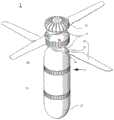
图1示出了本发明的一个实施例的透视图,其中叶片处于展开位置;Figure 1 shows a perspective view of one embodiment of the present invention with the blades in a deployed position;
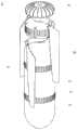
图2示出了图1的实施例的透视图,其中叶片处于缩回位置;Figure 2 shows a perspective view of the embodiment of Figure 1 with the vanes in a retracted position;
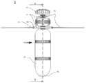
图3示出了图1的实施例的前视图;Figure 3 shows a front view of the embodiment of Figure 1;
图4示出了图1的实施例的俯视图;Figure 4 shows a top view of the embodiment of Figure 1;
图5示出了图1的实施例的仰视图;Figure 5 shows a bottom view of the embodiment of Figure 1;
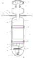
图6示出了对图1的实施例沿着图3的6-6线截取时获得的横截面图;Figure 6 shows a cross-sectional view of the embodiment of Figure 1 taken along line 6-6 of Figure 3;
图7示出了图1的实施例的分解图;Figure 7 shows an exploded view of the embodiment of Figure 1;
图8示出了CPU控制器的一个实施例的详图;Figure 8 shows a detailed view of one embodiment of a CPU controller;
图9示出了CPU控制器的另一个详图;Figure 9 shows another detailed view of the CPU controller;
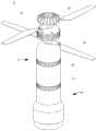
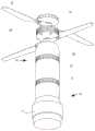
图10示出了具有嗅探头的一个实施例的透视图;Figure 10 shows a perspective view of one embodiment with a sniffing probe;
图11示出了图10的实施例的另一个透视图;Figure 11 shows another perspective view of the embodiment of Figure 10;
图12示出了示例性嗅探头的前视图;Figure 12 shows a front view of an exemplary sniffing probe;
图13示出了嗅探头的侧视图;Figure 13 shows a side view of the sniffing probe;
图14示出了嗅探头的俯视图;Figure 14 shows a top view of the sniffing probe;
图15示出了嗅探头的仰视图;Figure 15 shows a bottom view of the sniffing probe;
图16示出了嗅探头的分解图;Figure 16 shows an exploded view of the sniffing probe;
图17示出了对嗅探头沿着图12的17-17线截取时获得的横截面图;Figure 17 shows a cross-sectional view of the sniffing probe taken along line 17-17 of Figure 12;
图18示出了具有处于收缩位置的照明头的一个实施例的透视图;Figure 18 shows a perspective view of one embodiment with the illumination head in a retracted position;
图19示出了图18的实施例处于展开位置时的透视图;Figure 19 shows a perspective view of the embodiment of Figure 18 in a deployed position;
图20示出了图18的实施例的处于缩回位置时的另一个透视图;Figure 20 shows another perspective view of the embodiment of Figure 18 in a retracted position;
图21示出了图18的实施例处于展开位置时的另一个透视图;Figure 21 shows another perspective view of the embodiment of Figure 18 in a deployed position;
图22示出了照明头的前视图;Figure 22 shows a front view of the illumination head;
图23示出了照明头的侧视图;Figure 23 shows a side view of the illumination head;
图24示出了照明头的俯视图;Figure 24 shows a top view of the illumination head;
图25示出了照明头的仰视图;Figure 25 shows a bottom view of the illumination head;
图26示出了照明头的分解图;Figure 26 shows an exploded view of the illumination head;
图27示出了照明头的横截面图;Figure 27 shows a cross-sectional view of the illumination head;
图28示出了具有电磁脉冲(EMP)头的一个实施例的透视图;Figure 28 shows a perspective view of one embodiment with an electromagnetic pulse (EMP) head;
图29示出了图28的实施例的另一个透视图;Figure 29 shows another perspective view of the embodiment of Figure 28;
图30示出了EMP头的前视图;Figure 30 shows a front view of the EMP head;
图31示出了EMP头的侧视图;Figure 31 shows a side view of the EMP head;
图32示出了EMP头的俯视图;Figure 32 shows a top view of the EMP head;
图33示出了EMP头的仰视图;Figure 33 shows a bottom view of the EMP head;
图34示出了EMP头的分解图;Figure 34 shows an exploded view of the EMP header;
图35示出了对EMP头沿图30的35-35线截取时获得的横截面图;和Figure 35 shows a cross-sectional view of the EMP head taken along line 35-35 of Figure 30; and
图36示出了遥控装置的一个示例性实施例。Figure 36 shows an exemplary embodiment of a remote control device.
具体实施方式Detailed ways
现在请参考附图,其中示出本发明的方法和结构的一些示例性实施例。Reference is now made to the accompanying drawings, in which some exemplary embodiments of the methods and structures of the present invention are shown.
所示的军械1的实施例将有效载荷与无人驾驶飞行装置相结合,该无人驾驶飞行装置在此称为同轴无人机,它与在授予Ascent AeroSystems,LLC的美国专利10,093,417中所述的无人机类似。在其他实施例中,军械1可包括适合于向目标投送的无人驾驶飞行器(UAV)的其他设计。军械1包括一体形成的UAV功能,其飞行可在现场控制以到达目标上方的选定高度和位置,而不是由飞行器携带和发射的爆炸性武器或由这种飞行器携带的有效载荷“投放”装置。一旦军械1就位,就可对其进行控制,使其整体落在目标上。The embodiment of
图1提供了处于通电形态的军械1的视图,其中螺旋桨/旋转叶片38处于展开状态,以准备飞行。该军械包括上壳体41和下壳体43。图2提供了军械1在叶片38缩回时的视图。图1-3示出了军械1的部件的布置,当军械1相对于地平面处于部署后的竖直方位时,上壳体41的第一上端部5位于上壳体41的相对的第二下端部6上方。图4和图5分别以俯视图和仰视图示出了该军械。FIG. 1 provides a view of the
如图6所示,上壳体41包含电机46,电机轴45延伸到超过上壳体41的第一上端部5的位置,该轴45联接为与旋转叶片38(也称为螺旋桨)接合。螺旋桨38通过齿轮轴37联接至电机轴45。收发器36和天线安装在军械1的最上端的电机轴45上方。电池47被示为在电机46下方安装在上壳体41内,以给电机46提供动力,并使叶片38从缩回位置移动至操作位置,然后产生推力以举升和操纵军械1。热成像摄像头52被示为位于下壳体43的最低部分,处于允许摄像头52沿着地平面捕获视场的位置。基于微处理器的系统50位于炸药和热成像摄像头52之间。圆顶44可遮盖摄像头52。As shown in Figure 6, the
图7提供了军械1的分解透视图,图8和图9提供了下壳体43的部件的详图,包括基于微处理器的系统(中央处理器/控制器)50、撞击引信49或由撞击按钮开关51点燃的装药、以及热成像摄像头52。在与地面碰撞时触发引信49的按钮开关51位于基于微处理器的系统50与热成像摄像头52之间,但是也可使用其他组件布置形式和序列。基于微处理器的系统50被示为容纳在微型计算机板上(例如,1GHz单核CPU、512MB RAM、Mini HDMI和USB连接器、兼容Hat的40针头端、复合视频输出、CSI摄像头连接器、蓝牙和802.11Wifi连接),该微型计算机板控制摄像头52和屏幕标线。所述系统还提供全球定位系统(GPS)信息。例如,摄像头52可以是具有辐射测量能力的长波红外(LWIR)摄像头,该摄像头具有一个或多个80×60有效像素的焦平面阵列、带有增强红外传感器的非冷却热成像器、以及50度视场。为圆顶44选择的材料可以是锗玻璃,这种玻璃在红外区内具有透明性质,最好用作热成像的前光学器件。在一些实施例中,可能不需要圆顶44,因而摄像头的镜头从下壳体43突出。Figure 7 provides an exploded perspective view of the
军械1用于在遥控飞行导航下空中投送至目标。所述导航可由从地面发射军械1的人员来进行。在军械1上产生视频馈送的摄像头52可以是CCD摄像头、红外或热成像摄像头、或其他类型的成像装置。但是,出于说明的目的,在以下实施例中,该成像装置可称为热成像摄像头52,但不限于此。热成像摄像头52布置在军械1上,以在飞行期间向遥控装置3提供地平面的视图。在一些实施例中,摄像头52向下朝向地平面,以给出目标区域的有用视图,并帮助瞄准或引导军械1下降到下方的目标上。
从图1能够看出,军械1包括接收器或收发器36,该接收器或收发器用于接收和发送飞行控制数据、成像、有效载荷控制、以及需要向军械1发送或从军械1发送的任何其他数据。As can be seen from FIG. 1 ,
军械1的提供UAV功能的示例性部分包括具有第一和第二相对端部5和6的轴对称管状体形式的上壳体41。在一些实施例中,上壳体41的第一上端部5和第二下端部6通过第一联接器20彼此连接。第一联接器20可包括用于将上壳体41可拆卸地配合连接至下壳体43的螺纹部分。或者,联接器20的功能可通过夹装或使用紧固件或不可移除的连接器装置来实现。上壳体41可由ABS管形成。An exemplary portion of the
可部署的旋转叶片38连接在上壳体41的第一上端部5处或附近。在上壳体41的第一上端部5中还可布置电机46。电机46的操作可由遥控装置3控制,并通过与相邻的电池单元47的连接供电。随着遥控装置3有选择性地产生可变水平的电力,电机46可操作从而以可变水平的推力部署并旋转叶片38。在处于部署状态时,叶片38围绕上壳体41旋转以施加推力,以沿着地平面行进,并将军械1带到目标位置上方的第一高度处。A deployable
在图1-9所示的实施例中,叶片38围绕旋转中心轴线位于两个竖直高度,但是也可采用其他公知的叶片结构。叶片38可包括由销39连接的偏压单元或弹簧装置40,这使得叶片38在被部署时能够从缩回位置展开。这样,军械1在不使用时更易运输。In the embodiment shown in Figures 1-9, the
当军械1处于目标上方的期望位置时,遥控装置3可使旋转动力断开,导致叶片38停止旋转并缩回,从而使得军械1在重力作用下朝目标向下行进,从而有效地作为炸弹。在其他实施例中,产生旋转动力的系统可配置为允许叶片反向旋转操作,使得电机在叶片38不缩回的情况下朝着目标向下驱动军械1。概括地说,根据特定的任务和有效载荷,可缩回叶片以使军械1更安静地并以更小的阻力接近目标,或者可利用向下推力驱动叶片以使军械1更有力、更迅速地接近目标。When the
根据任务需求,所述有效载荷可以是炸药48、化学/生物/放射检测单元、照明单元(例如发光二极管阵列)、电磁脉冲装置、或其他有用的有效载荷。示例性的有效载荷可布置在下壳体43中。下壳体43可以是模块化的或可拆卸的,以便更换为不同类型的有效载荷。Depending on mission requirements, the payload may be
军械1的爆炸部件48可以是容纳在圆柱形对称下壳体43内的圆柱形状,它附接为与上壳体41共享一个对称轴线。军械1的下壳体43位于上壳体41的第二下端部6的下方,通过第二联接器11附接至上壳体41。第二联接器11可包括配合螺纹,或者该功能可通过其他联接装置实现,例如相对于联接器20说明的联接装置。下壳体43也可由ABS管形成。在所示的布置形式中,电池47位于上壳体41的第二下端部6,在电机46下方,而爆炸部件48容纳在下壳体43的上部中。The
请参考图7-9,包括诸如基于微处理器的系统等部件的电子控制单元50位于下壳体43中,在爆炸部件48的下方。热成像摄像头52在下壳体43的最下部安装在基于微处理器的系统50的下方,容纳在下壳体43的具有透明圆顶44的部分中。圆顶44使得摄像头的镜头能够在飞行期间提供地平面上方的广角视野。在军械1的飞行期间,摄像头52对所关注的地面或地面结构的部分进行成像,以通过射频链路显示在遥控装置3上。用遥控装置3对军械1进行导航的人员能够将军械1沿着地平面引导到目标上方的可选位置处。Referring to FIGS. 7-9 , an
基于微处理器的系统50可包括CPU以及其他控制和存储系统。基于微处理器的系统50可允许自动地或以其他方式处理某些飞行属性,以提供飞行辅助、障碍闪避、自动驾驶、目标检测、瞄准目标、群集能力、以及可由计算机系统执行的任何其他适当功能。Microprocessor-based
爆炸部件48可用撞击引信49引爆(例如由硝酸铵和金属(例如铝粉)的组合形成,以在撞击力下爆炸)。撞击引信49也可连接至按钮/开关51以触发引爆。The
在一个示例性实施例中,用作撞击引信49的材料是商售的电子引爆雷管M6组件,该组件还具有包含作为按钮/开关的点火装药的铝合金杯。该装药由无烟火药、氯酸钾和二硝基铅盐、邻甲酚和RDX(O2NNCH2)3底药组成。由点火装药中的桥接线(产生火花)连接的两根引线穿过所述杯的开口端中的橡胶(或橡胶和硫)塞子组件,在这种配置中,该组件用作按钮/开关51。两个外周压圈将塞子组件固定在杯子中。另外,按钮/开关51可包括电子引爆电路以便触发撞击引信49,而不需要军械1与地面或其他物体撞击。这种引爆电路会对遥控装置3发出的引爆引信49和爆炸部件48的命令做出响应。由撞击引信49引爆的部件48可以是塑性炸药(例如C-4炸药)、或者是硝酸铵或高氯酸铵与金属(例如铝)的组合。In one exemplary embodiment, the material used for
对遥控装置3的设计和功能没有特别限制,并且遥控装置3能够直接或间接地与军械1通信。例如,该遥控装置可以是智能电话、单带宽或多带宽遥控器、防御系统、或任何其他适当的控制装置。图36示出了一种市场上可买到的遥控装置3,该遥控装置可包括用于显示来自摄像头52的图像的显示器71、以第一频率(例如2.4GHz)广播的第一天线72、以及以第二频率(例如5.8GHz)广播的第二天线73。所示的装置3包括油门/方向舵操纵杆74和升降舵/副翼操纵杆75。装置3还包括电源按钮76、启动按钮77、万向节控制器78、辅助显示器79,并且可具有用于特定功能的各种其他控制部件。The design and function of the
军械1在战斗环境或存在狙击手的情况下很有用,在这种情况下试图观察敌方的位置时视觉暴露的危险较高。在一个示例性实施例中,包括同轴无人机的军械1可携带在背包中;可从手上发射;并且可远程飞越目标,同时通过热成像提供目标视图的实时视频馈送。当在热成像图像中发现目标并且军械1位于目标正上方时,遥控装置3上的按钮命令被激活,以停止旋转叶片38,并且使无人机在重力作用下作为炸弹下落到目标上,并在撞击时爆炸。
在本文中说明了一种军械,该军械在被军队人员发射时在飞行中是可控制的。这样能够在飞行中选择目的地,并且发射该军械的人员能够根据从军械获取的信息改变目的地。所公开的军械较轻且较紧凑,适合于放在背包中携带。在一种设计中,该军械限制为20英寸(51厘米)长度,由电池47供电,飞行时间为30分钟,同时携带两公斤有效载荷。Described herein is an ordnance that is controllable in flight when launched by military personnel. This enables the destination to be selected on the fly, and the person launching the ordnance can change the destination based on the information obtained from the ordnance. The disclosed ordnance is lighter and more compact, suitable for being carried in a backpack. In one design, the ordnance is limited to 20 inches (51 cm) in length, powered by
在此实施例中,军械1可用手部署。例如,士兵操作人员可手动打开电源以使旋转叶片38开始旋转以进行发射,然后操作人员可通过射频(RF)驱动的遥控装置3控制军械1的运动。当军械1在飞行时,操作人员可通过观察遥控装置上的监视器来观察其在地面上方的位置。显示基于来自军械1的实时馈送。当操作人员发现军械1下方的目标时,可使用遥控装置3立即停止并折叠旋转叶片38(在一些实施例中,旋转叶片38可以是通过偏压装置或弹簧21来加载的),使军械1能够直接落在所选目标上。在与目标的表面接触时,撞击引信49引爆炸药,并保证最大限度地减少附带损害。若需要避免在地面上造成爆炸损坏,则可使用遥控装置3来引爆炸药48。In this embodiment, the
本发明使士兵能够携带强大、重量轻、并可通过热标线和遥控显示器71高精度地远程投放的弹药。可引导军械1穿过建筑物(例如穿过敞开的窗户),并使其穿过竖井等下落,几乎不会造成任何附带损害。军械1还可配有红外(LED)灯,以提供沿着地平面的照明,并确保目标的识别。此外,为了便于行进到期望的目的地,操作人员可指定特定的GPS目标位置和目标位置上方的高度。即使在GPS坐标不在操作人员的视线范围内的情况下,军械1也可编程为自动落在该位置。军械1可使用多种引信操作。可替换引信类型,以适应政策和安全规程以及军火兼容性。The present invention enables soldiers to carry ammunition that is powerful, lightweight, and can be delivered remotely with high accuracy via the thermal reticle and
所示的实施例包括一种无人机炸弹系统,这是一种设计为用爆炸弹头或其他常规和非常规的专用弹头来攻击视线内和视线外的地面目标的无人驾驶同轴飞行器。这些实施例是一种便携式巡飞弹药,它能够为地面战斗人员提供制导或可引导的精确弹药。所述系统配有高分辨率光电和/或红外摄像头,使寻找目标的人员能够定位、监视和引导飞行器到达目标处。这些实施例的一个有利特征是能够在攻击之前在空中“巡飞”一段较长时间,为寻找目标的人员提供时间来决定攻击的时机以及要攻击的目标。这一特征允许在投放弹药之前撤回;并允许战斗人员对事故和地面状况做出弥补。这与常规导弹不同,常规导弹无法召回或在撞击之前无法引爆,而这可能危及地面人员。The illustrated embodiment includes a drone bomb system, an unmanned coaxial vehicle designed to attack ground targets in and out of line of sight with an exploding warhead or other conventional and unconventional specialized warheads. These embodiments are portable loitering munitions capable of providing guided or steerable precision munitions to ground combatants. The system is equipped with high-resolution electro-optical and/or infrared cameras to enable target seekers to locate, monitor and guide the aircraft to the target. An advantageous feature of these embodiments is the ability to "fly" in the air for an extended period of time prior to an attack, giving target seekers time to decide when to attack and what to target. This feature allows for withdrawal before munitions are dropped; and allows combatants to compensate for accidents and ground conditions. This is different from conventional missiles, which cannot be recalled or detonated before impact, which could endanger people on the ground.
越来越多的作战行动可受益于所公开的巡飞弹药的实施例,这种弹药与火箭和迫击炮等其他常规武器相比提供了一些独特的新能力。与迫击炮、火箭和小型导弹等武器相比,这种优点之一是提高了区分战斗人员和非战斗人员的能力。巡飞能力允许用户在攻击前长时间探测和跟踪潜在目标。这能够最大限度地减少对非敌对目标的附带损害。A growing number of combat operations may benefit from the disclosed embodiments of loitering munitions, which provide some unique new capabilities compared to other conventional weapons such as rockets and mortars. One of this advantages over weapons such as mortars, rockets and small missiles is the improved ability to distinguish combatants from non-combatants. The loitering capability allows users to detect and track potential targets long before an attack. This minimizes collateral damage to non-hostile targets.
所示实施例的另一个优点是与同等武器相比精度更高。这些实施例产生向前的爆炸,这种定向爆炸比产生360度爆炸的手榴弹更精确。所公开的巡飞弹药是可操纵的,而其他弹药是不可操纵的。Another advantage of the embodiment shown is the greater accuracy compared to equivalent weapons. These embodiments produce a forward blast that is more precise than a grenade that produces a 360-degree blast. The disclosed loitering munitions are steerable, while other munitions are not.
此外,“放弃”特征允许无人机炸弹系统的操作人员无害地取消半途中的攻击并放弃弹药。常规的火箭、迫击炮和导弹没有这种特征。本发明的一些实施例还提供了可互换的弹头,以允许将无人机炸弹系统从致命武力变为非致命和战略性的用途。在图10-17中示出的一个此类示例性实施例包括作为有效载荷的核生物和化学(NBC)嗅探头53,该嗅探头53可飞过一个区域并获取空气样品,以检测NBC污染物的存在,从而不会使进入隔离区域的人员处于危险之中。请参考图16的分解图,嗅探头53可包括主体外壳54、电池47、CPU/控制器系统50、以及格栅56,该格栅56布置为有助于将微型真空器55保持在靠近通气口57的位置。In addition, the "abandon" feature allows the operator of the UAV bomb system to harmlessly cancel the midway attack and drop the munitions. Conventional rockets, mortars and missiles do not have this feature. Some embodiments of the present invention also provide interchangeable warheads to allow UAV bomb systems to be changed from lethal force to non-lethal and strategic use. One such exemplary embodiment, shown in Figures 10-17, includes as a payload a nuclear biological and chemical (NBC) sniffing
在图18-27中示出了军械1的另一个示例性实施例,图中示出了具有照明头58的有效载荷。照明头58可以是任何类型的照明装置。在图18-27所示的示例中,照明头58包括伞型机构59、膜或反射盖60、以及LED阵列/灯条61。LED灯条61可由带有3MTM背胶的LED条形灯形成,每个灯条具有54个LED灯,每个灯条的延伸长度为36英寸。这些灯条采用齐切连接,因此每三个LED切割成一定长度。12V灯条为无色或红色的,具有IP67防水防尘等级。所述LED可以是任何颜色的,这取决于特定的任务。LED灯条61还可产生红外光,以辅助夜视。Another exemplary embodiment of
如图18和20所示,伞型机构59可保持关闭,直到激活照明头58的时候。这使得存储和运输更容易,飞行特性和隐身性更好。如图19和21所示,一旦就位,伞型机构59可展开,使得反射罩60打开,并将LED灯条61置于适当位置,以照亮期望的区域(在此示例中通常是地面区域)。这种装置可代替寿命较短的照明弹,这种可能会导致火灾,并且不能“关闭”。相比之下,本发明的照明阵列可像灯开关一样在需要时开启和关闭。As shown in Figures 18 and 20, the
如图24-27所示,照明头58可包括电池47以及允许对目标区域进行更长时间的照明的附加电池63。还包括基于微处理器的控制系统50’,该系统控制照明系统以及军械1的其他功能。装置3用于控制系统50的功能。As shown in Figures 24-27, the
图28-35所示的实施例示出了一种用于使电子系统失效的电磁脉冲(EMP)弹头64。在一个实施例中,EMP弹头64包括附接机构,该附接机构允许所述装置落在电线杆或其他战略性的电子目标上,并自我附着到该目标上,例如通过磁体64附着到铁磁性表面上。所述装置然后可发出电磁脉冲使目标失效,而不会对基础设施造成严重损害。EMP弹头64包括电池47、微处理器系统50″、以及用于产生EMP脉冲的铜线圈66和电容67。在此实施例中,磁体68置于军械1的底端,允许军械1在发射EMP脉冲之前附着在降落的位置(或者附着在中间区域中,这取决于飞行特性和磁体的功率)。The embodiment shown in FIGS. 28-35 shows an electromagnetic pulse (EMP)
另一个选择是采用通过释放刺激物(梅斯,辣椒喷剂)来驱散人群的有效载荷。地面人员可通过使该装置飞过抗议人群来瞄准特定人群区域,并在特定人群正上方释放催泪瓦斯等,以避免影响无辜的旁观者。也可在整个人群中均匀地散布瓦斯,以避免使用可能伤人或被向维和人员回掷的射弹。Another option is to employ payloads that disperse crowds by releasing irritants (mace, pepper spray). Ground personnel can target specific crowd areas by flying the device over protesting crowds, and release tear gas, etc. directly above specific crowds to avoid affecting innocent bystanders. The gas can also be distributed evenly throughout the population to avoid the use of projectiles that could injure people or be thrown back at peacekeepers.
在一些实施例中,所述有效载荷可包括高能磷弹头,该弹头例如可通过磁体附着到坦克或其他车辆或设备上,然后点燃以烧穿金属或其他材料,使目标失效。装甲车、飞机和雷达、设备都是典型的目标。In some embodiments, the payload may include a high-energy phosphorous warhead, which may be attached to a tank or other vehicle or equipment, such as by magnets, and then ignited to burn through metal or other materials, rendering the target ineffective. Armored vehicles, aircraft and radar, equipment are typical targets.
除了具有适应性强的有效载荷的实施例之外,本发明还可根据任务升级,以包括不同规格的无人机/有效载荷包。例如,所公开的无人机炸弹系统是可升级的,并且可按多种(例如三种)规格提供。因此,一个实施例可以是手持规格的小型系统,其长度大约为8英寸,并以类似于M203手榴弹的方式附在士兵的MOLLE背心的袋中。这种装置可能仅包括致命的有效载荷弹头,可小到允许一名士兵携带多个装置,并将这些装置远程引导至目标,而士兵绝不会暴露在较大危险中。这种军械可取代或改善目前使用的许多武器,例如迫击炮和M203榴弹发射器型系统。In addition to embodiments with adaptable payloads, the present invention may be mission-upgradable to include different sized drone/payload packages. For example, the disclosed drone bomb system is scalable and available in multiple (eg, three) sizes. Thus, one embodiment could be a small system in a handheld format, approximately 8 inches in length, and attached to the pocket of a soldier's MOLLE vest in a manner similar to an M203 grenade. Such devices, which may include only a lethal payload warhead, could be small enough to allow a single soldier to carry multiple devices and direct them to a target remotely without exposing the soldier to greater danger. This ordnance could replace or improve many weapons currently in use, such as mortars and M203 grenade launcher-type systems.
其他可能的实施例包括中型系统,这种系统具有可互换的弹头,长度大约为22英寸,可附在士兵的背包上,装在附着到MOLLE系统上的管中。一些实施例可以是大型系统,这种系统例如大约为6英尺长,能携带能够夷平恐怖分子营地的致命有效载荷。这种实施例与军方的自动飞行软件兼容,并且可在50英里或更远的距离投送。Other possible examples include a medium-sized system with interchangeable warheads, approximately 22 inches in length, that attaches to a soldier's backpack, and that fits in a tube that attaches to the MOLLE system. Some embodiments may be large systems, eg, approximately 6 feet long, capable of carrying lethal payloads capable of razing terrorist camps. Such an embodiment is compatible with the military's autoflight software and can be delivered over distances of 50 miles or more.
由于公开的无人机炸弹系统是一种具有精确定位特点的高效的有效载荷投送系统,因此敌人的掩护价值可能被完全抵消。该系统可以是手持便携式无人机炸弹的形式,可消灭狙击手或隐藏目标,同时,更重要的可能是不再需要士兵从掩体后面暴露自己。利用遥控装置,士兵可从背包中更安全地发射具有热成像能力的无人机炸弹系统。22英寸长的无人机炸弹系统的重量可能为5磅,有效作战范围为25公里。当无人机炸弹系统的同轴UAV位于其目标上方并且目标位于士兵的显示单元的热标线中时,可利用重力或反推力将炸药投放到目标上。在投送致命炸药有效载荷的同时,能够避免其他武器可能造成的附带伤害。预计该无人机炸弹系统能为士兵提高500%命中率。Since the disclosed UAV bomb system is an efficient payload delivery system with pinpointing characteristics, the enemy's cover value may be completely negated. The system could be in the form of a hand-held portable drone bomb that could take out snipers or hidden targets, while, perhaps more importantly, eliminating the need for soldiers to reveal themselves from behind cover. Using a remote control unit, soldiers can more safely launch thermal imaging-capable drone bomb systems from their backpacks. A 22-inch-long drone bomb system could weigh 5 pounds and have an effective operational range of 25 kilometers. When the coaxial UAV of the UAV bomb system is over its target and the target is in the thermal reticle of the soldier's display unit, the explosives can be dropped on the target using gravity or reverse thrust. Delivers deadly explosive payloads while avoiding the collateral damage that other weapons can inflict. It is expected that the drone bomb system can increase the hit rate of soldiers by 500%.
虽然本发明是通过示例性实施例示出的,但是本发明不限于此。因此,本公开的范围仅由所附权利要求限定,每项权利要求构成一个独立的实施例。实施例可将不同的权利要求进行组合。不同实施例的组合在权利要求的范围之内,并且在阅读本公开之后对于本领域普通技术人员来说是显而易见的。Although the present invention has been shown by way of exemplary embodiments, the present invention is not limited thereto. Accordingly, the scope of the present disclosure is to be limited only by the appended claims, with each claim forming a separate embodiment. Embodiments may combine different claims. Combinations of the different embodiments are within the scope of the claims and will be apparent to those of ordinary skill in the art after reading this disclosure.
Claims (20)
Applications Claiming Priority (5)
| Application Number | Priority Date | Filing Date | Title |
|---|---|---|---|
| US201762568518P | 2017-10-05 | 2017-10-05 | |
| US62/568518 | 2017-10-05 | ||
| US201862726976P | 2018-09-04 | 2018-09-04 | |
| US62/726976 | 2018-09-04 | ||
| PCT/US2018/054767WO2019177664A1 (en) | 2017-10-05 | 2018-10-05 | Remotely controllable aeronautical ordnance |
Publications (1)
| Publication Number | Publication Date |
|---|---|
| CN111770881Atrue CN111770881A (en) | 2020-10-13 |
Family
ID=65993095
Family Applications (1)
| Application Number | Title | Priority Date | Filing Date |
|---|---|---|---|
| CN201880064739.5APendingCN111770881A (en) | 2017-10-05 | 2018-10-05 | Remote Controlled Aviation Ordnance |
Country Status (18)
| Country | Link |
|---|---|
| US (2) | US11067374B2 (en) |
| EP (1) | EP3691969A4 (en) |
| JP (1) | JP7237070B2 (en) |
| KR (1) | KR102684429B1 (en) |
| CN (1) | CN111770881A (en) |
| AU (3) | AU2018413298B2 (en) |
| BR (1) | BR112020006858A2 (en) |
| CA (1) | CA3078211A1 (en) |
| IL (1) | IL273660B (en) |
| JO (1) | JOP20200084A1 (en) |
| MX (1) | MX2020004357A (en) |
| PH (1) | PH12020550165A1 (en) |
| RU (1) | RU2020115187A (en) |
| SA (1) | SA520411690B1 (en) |
| SG (1) | SG11202003095TA (en) |
| UA (1) | UA127762C2 (en) |
| WO (1) | WO2019177664A1 (en) |
| ZA (2) | ZA202002331B (en) |
Cited By (3)
| Publication number | Priority date | Publication date | Assignee | Title |
|---|---|---|---|---|
| RU2769180C1 (en)* | 2021-04-22 | 2022-03-29 | Акционерное общество "Государственное научно-производственное предприятие "Регион" | Aerodynamic layout of a controlled gliding aerial bomb |
| CN115056984A (en)* | 2022-07-25 | 2022-09-16 | 哈尔滨工业大学 | Microminiature load dispenser and dispensing method |
| CN118124838A (en)* | 2024-05-08 | 2024-06-04 | 杭州而墨农业技术有限公司 | Seedling condition and pest and disease damage early warning patrol unmanned aerial vehicle and method |
Families Citing this family (26)
| Publication number | Priority date | Publication date | Assignee | Title |
|---|---|---|---|---|
| KR101917785B1 (en)* | 2016-10-26 | 2019-01-29 | 한국항공우주연구원 | Non-motorized type flying unit for observation |
| US12031802B2 (en) | 2017-07-26 | 2024-07-09 | Northrop Grumman Systems Corporation | Despun wing control system for guided projectile maneuvers |
| CN111770881A (en)* | 2017-10-05 | 2020-10-13 | 欧弗沃克斯有限公司 | Remote Controlled Aviation Ordnance |
| US11578956B1 (en)* | 2017-11-01 | 2023-02-14 | Northrop Grumman Systems Corporation | Detecting body spin on a projectile |
| CN108298064B (en)* | 2017-11-09 | 2024-04-26 | 青岛兰道尔空气动力工程有限公司 | Unconventional yaw control system |
| GB2586843B (en)* | 2019-09-05 | 2023-03-29 | Bae Systems Plc | Improvements in and relating to a guided weapon |
| GB2586854B (en) | 2019-09-06 | 2023-05-17 | Bae Systems Plc | Improvements in and relating to weapon control |
| US11385037B2 (en)* | 2019-12-10 | 2022-07-12 | Hanwha Corporation | Electronic detonation device with dual antenna for blasting system and blasting system using same |
| CN111099018B (en)* | 2019-12-26 | 2021-10-22 | 浙江海洋大学 | Material delivery device and control method for maritime unmanned aerial vehicle |
| CN111156865A (en)* | 2020-01-07 | 2020-05-15 | 北京理工大学 | A coaxial multi-rotor cruise missile |
| KR102312650B1 (en)* | 2020-06-17 | 2021-10-13 | 주식회사 한화 | Free-fall warhead with precession motion control |
| KR102330716B1 (en)* | 2020-06-30 | 2021-11-25 | 주식회사 풍산 | Diving Drone Assembly |
| IL275792B (en)* | 2020-07-01 | 2021-08-31 | Imi Systems Ltd | Incoming aerial threat protection system and method |
| CN113085462B (en)* | 2021-04-23 | 2023-06-13 | 南京航空航天大学 | Cross-medium unmanned aerial vehicle device and control method thereof |
| KR102483718B1 (en)* | 2021-05-12 | 2023-01-03 | 주식회사 에아가이아 | Portable dron bomb device for military |
| WO2023027817A2 (en)* | 2021-07-09 | 2023-03-02 | Cheytac Usa Inc. | Advanced projectile with removable tips |
| US11650036B2 (en) | 2021-07-12 | 2023-05-16 | Ensign-Bickford Aerospace & Defense Company | Payload platform for unmanned vehicles |
| CN113847850B (en)* | 2021-08-30 | 2023-03-24 | 西安近代化学研究所 | War inducing device for realizing mechanical transmission by utilizing wind resistance to transmit power |
| CN114322675A (en)* | 2021-11-30 | 2022-04-12 | 上海机电工程研究所 | Deformable ejector rod and foldable control surface structure in foldable rudder of guided missile and guided missile |
| US12313389B1 (en) | 2022-03-11 | 2025-05-27 | Northrop Grumman Systems Corporation | Tunable safe and arming devices and methods of manufacture |
| JP2023178936A (en)* | 2022-06-06 | 2023-12-18 | 和浩 山本 | Falling trajectory control system |
| PL441807A1 (en)* | 2022-07-21 | 2024-01-22 | Filipek-Motors Spółka Z Ograniczoną Odpowiedzialnością | Foldable drone |
| USD1078914S1 (en)* | 2022-12-15 | 2025-06-10 | CaptureTec LLC | Payload container |
| KR102794114B1 (en) | 2023-03-13 | 2025-04-14 | 주식회사 플러스인 | Educational drone equipped with a means of dropping |
| KR102826675B1 (en)* | 2023-09-18 | 2025-06-27 | 태경전자주식회사 | Drone that provides lighting function |
| KR102711114B1 (en)* | 2024-02-05 | 2024-09-27 | 주식회사 호운 | Launch and Recovery Vehicle for Reconnaissance Drones |
Citations (6)
| Publication number | Priority date | Publication date | Assignee | Title |
|---|---|---|---|---|
| CN2416481Y (en)* | 2000-04-07 | 2001-01-24 | 李国红 | Shell for striking airplane and air paraboy |
| US20050051667A1 (en)* | 2001-12-21 | 2005-03-10 | Arlton Paul E. | Micro-rotorcraft surveillance system |
| CN102596722A (en)* | 2009-09-09 | 2012-07-18 | 威罗门飞行公司 | Systems and apparatus for detonation-suppressed transmitters with portable RF transparent transmitter tubes for remote-working unmanned aerial vehicles |
| US20120211589A1 (en)* | 2005-06-20 | 2012-08-23 | Burak Uzman | Remotely-guided vertical take-off system and method for delivering an ordnance to a target |
| US8985025B1 (en)* | 2011-12-06 | 2015-03-24 | The United States Of America As Represented By The Secretary Of The Army | Submunition and cluster munition containing submunitions |
| US20150247714A1 (en)* | 2012-04-25 | 2015-09-03 | Wilcox Industries Corp. | Modular rocket system |
Family Cites Families (16)
| Publication number | Priority date | Publication date | Assignee | Title |
|---|---|---|---|---|
| US5657947A (en)* | 1994-08-24 | 1997-08-19 | Loral Corp. | Precision guidance system for aircraft launched bombs |
| JP2000266499A (en) | 1999-03-16 | 2000-09-29 | Toshiba Corp | Anti-aircraft defense device |
| CN102173310B (en)* | 2004-04-14 | 2013-11-13 | 保罗·E·阿尔托恩 | rotorcraft |
| US9434471B2 (en)* | 2005-04-14 | 2016-09-06 | Paul E Arlton | Rotary wing vehicle |
| US7854410B2 (en)* | 2006-05-15 | 2010-12-21 | Kazak Composites, Incorporated | Powered unmanned aerial vehicle |
| US7581702B2 (en)* | 2006-06-09 | 2009-09-01 | Insitu, Inc. | Wirelessly controlling unmanned aircraft and accessing associated surveillance data |
| US8328130B2 (en)* | 2008-12-08 | 2012-12-11 | Honeywell International Inc. | Vertical take off and landing unmanned aerial vehicle airframe structure |
| CA2759383C (en) | 2009-02-02 | 2017-11-21 | Aerovironment | Multimode unmanned aerial vehicle |
| US9308799B2 (en)* | 2011-03-29 | 2016-04-12 | Denso International America, Inc. | Variable evaporator outlet air pressure distribution |
| KR20150001821U (en) | 2013-11-05 | 2015-05-13 | 정선화 | Pan Tilt explosion and dust ignition proof camera with both side camera housing |
| CN113955094A (en)* | 2014-11-10 | 2022-01-21 | 上升航空系统股份有限公司 | unmanned aerial vehicle |
| WO2017040254A1 (en)* | 2015-08-28 | 2017-03-09 | Laufer Wind Group Llc | Mitigation of small unmanned aircraft systems threats |
| KR20170091263A (en)* | 2016-01-31 | 2017-08-09 | 자이로캠주식회사 | The drone with camera sensor and bomb for suicide bombing, and the remote control and monitoring device |
| US10655936B2 (en)* | 2016-10-28 | 2020-05-19 | Rosemount Aerospace Inc. | Coordinating multiple missile targeting via optical inter-missile communications |
| US10287010B2 (en)* | 2016-11-02 | 2019-05-14 | Bell Helicopter Textron Inc. | Rotor sequencing for dual rotor aircraft |
| CN111770881A (en)* | 2017-10-05 | 2020-10-13 | 欧弗沃克斯有限公司 | Remote Controlled Aviation Ordnance |
- 2018
- 2018-10-05CNCN201880064739.5Apatent/CN111770881A/enactivePending
- 2018-10-05AUAU2018413298Apatent/AU2018413298B2/enactiveActive
- 2018-10-05JOJOP/2020/0084Apatent/JOP20200084A1/enunknown
- 2018-10-05BRBR112020006858-6Apatent/BR112020006858A2/ennot_activeApplication Discontinuation
- 2018-10-05UAUAA202002672Apatent/UA127762C2/enunknown
- 2018-10-05JPJP2020520028Apatent/JP7237070B2/enactiveActive
- 2018-10-05EPEP18909554.0Apatent/EP3691969A4/enactivePending
- 2018-10-05USUS16/153,696patent/US11067374B2/enactiveActive
- 2018-10-05CACA3078211Apatent/CA3078211A1/enactivePending
- 2018-10-05WOPCT/US2018/054767patent/WO2019177664A1/ennot_activeCeased
- 2018-10-05KRKR1020207012796Apatent/KR102684429B1/enactiveActive
- 2018-10-05RURU2020115187Apatent/RU2020115187A/enunknown
- 2018-10-05SGSG11202003095TApatent/SG11202003095TA/enunknown
- 2018-10-05MXMX2020004357Apatent/MX2020004357A/enunknown
- 2020
- 2020-03-27PHPH12020550165Apatent/PH12020550165A1/enunknown
- 2020-03-27ILIL273660Apatent/IL273660B/enunknown
- 2020-03-30AUAU2020100488Apatent/AU2020100488A4/ennot_activeCeased
- 2020-04-02SASA520411690Apatent/SA520411690B1/enunknown
- 2020-05-04ZAZA2020/02331Apatent/ZA202002331B/enunknown
- 2021
- 2021-07-19USUS17/378,765patent/US11940251B2/enactiveActive
- 2022
- 2022-01-27ZAZA2022/01297Apatent/ZA202201297B/enunknown
- 2022-10-14AUAU2022252842Apatent/AU2022252842A1/ennot_activeAbandoned
Patent Citations (6)
| Publication number | Priority date | Publication date | Assignee | Title |
|---|---|---|---|---|
| CN2416481Y (en)* | 2000-04-07 | 2001-01-24 | 李国红 | Shell for striking airplane and air paraboy |
| US20050051667A1 (en)* | 2001-12-21 | 2005-03-10 | Arlton Paul E. | Micro-rotorcraft surveillance system |
| US20120211589A1 (en)* | 2005-06-20 | 2012-08-23 | Burak Uzman | Remotely-guided vertical take-off system and method for delivering an ordnance to a target |
| CN102596722A (en)* | 2009-09-09 | 2012-07-18 | 威罗门飞行公司 | Systems and apparatus for detonation-suppressed transmitters with portable RF transparent transmitter tubes for remote-working unmanned aerial vehicles |
| US8985025B1 (en)* | 2011-12-06 | 2015-03-24 | The United States Of America As Represented By The Secretary Of The Army | Submunition and cluster munition containing submunitions |
| US20150247714A1 (en)* | 2012-04-25 | 2015-09-03 | Wilcox Industries Corp. | Modular rocket system |
Cited By (4)
| Publication number | Priority date | Publication date | Assignee | Title |
|---|---|---|---|---|
| RU2769180C1 (en)* | 2021-04-22 | 2022-03-29 | Акционерное общество "Государственное научно-производственное предприятие "Регион" | Aerodynamic layout of a controlled gliding aerial bomb |
| CN115056984A (en)* | 2022-07-25 | 2022-09-16 | 哈尔滨工业大学 | Microminiature load dispenser and dispensing method |
| CN118124838A (en)* | 2024-05-08 | 2024-06-04 | 杭州而墨农业技术有限公司 | Seedling condition and pest and disease damage early warning patrol unmanned aerial vehicle and method |
| CN118124838B (en)* | 2024-05-08 | 2024-07-16 | 杭州而墨农业技术有限公司 | Seedling condition and pest and disease damage early warning patrol unmanned aerial vehicle and method |
Also Published As
| Publication number | Publication date |
|---|---|
| IL273660B (en) | 2022-02-01 |
| US11067374B2 (en) | 2021-07-20 |
| RU2020115187A3 (en) | 2021-12-20 |
| UA127762C2 (en) | 2023-12-27 |
| ZA202002331B (en) | 2023-01-25 |
| JOP20200084A1 (en) | 2020-04-30 |
| US20190107374A1 (en) | 2019-04-11 |
| EP3691969A1 (en) | 2020-08-12 |
| WO2019177664A1 (en) | 2019-09-19 |
| US11940251B2 (en) | 2024-03-26 |
| PH12020550165A1 (en) | 2021-02-22 |
| KR20200057777A (en) | 2020-05-26 |
| KR102684429B1 (en) | 2024-07-11 |
| AU2022252842A1 (en) | 2022-11-10 |
| JP2020537736A (en) | 2020-12-24 |
| US20220163304A1 (en) | 2022-05-26 |
| IL273660A (en) | 2020-05-31 |
| JP7237070B2 (en) | 2023-03-10 |
| AU2020100488A4 (en) | 2020-05-14 |
| BR112020006858A2 (en) | 2020-10-06 |
| SG11202003095TA (en) | 2020-05-28 |
| AU2018413298B2 (en) | 2022-07-14 |
| AU2018413298A1 (en) | 2020-04-16 |
| CA3078211A1 (en) | 2019-09-19 |
| ZA202201297B (en) | 2024-03-27 |
| EP3691969A4 (en) | 2020-11-11 |
| SA520411690B1 (en) | 2022-07-03 |
| MX2020004357A (en) | 2020-10-05 |
| RU2020115187A (en) | 2021-11-09 |
Similar Documents
| Publication | Publication Date | Title |
|---|---|---|
| US11940251B2 (en) | Remotely controllable aeronautical ordnance | |
| US11753160B2 (en) | Unmanned aerial vehicle | |
| US10099785B1 (en) | Drone with ring assembly | |
| US20220170725A1 (en) | Visual guidance system for barrel-fired projectiles | |
| US8314374B2 (en) | Remotely-guided vertical take-off system and method for delivering an ordnance to a target | |
| US8648285B2 (en) | Remotely guided gun-fired and mortar rounds | |
| ES2452068T3 (en) | Guided weapon with multiple fuse modes switchable in flight | |
| KR101188294B1 (en) | Unmanned aerial vehicle for electronic warfare which uses jet engine | |
| KR20080037434A (en) | Self-contained unmanned aerial vehicle with camera and remote control for him | |
| WO2019046911A1 (en) | Unmanned aerial vehicle | |
| KR102483718B1 (en) | Portable dron bomb device for military | |
| RU2558528C1 (en) | Drone strike complex | |
| CN103471472A (en) | Aerial anti-terrorist unit for firing mini-rocket to propel special ammunition | |
| US20240286774A1 (en) | Unmanned aerial vehicle, control method, and unmanned aerial vehicle defense system | |
| JP5547435B2 (en) | Landing observation system | |
| AU2017228525B2 (en) | Unmanned aerial vehicle | |
| RU2681826C2 (en) | Unmanned missile strike system | |
| RU233813U1 (en) | A destructive device for dropping from an unmanned aerial vehicle | |
| RU2818378C1 (en) | Combat multicopter with cumulative projectile | |
| Urinov | COMBAT DRONES–DANGEROUS AND PERSPECTIVE WEAPON OF THE FUTURE ARMED CONFLICT | |
| WO2025048757A1 (en) | An unmanned aerial vehicle with explosives |
Legal Events
| Date | Code | Title | Description |
|---|---|---|---|
| PB01 | Publication | ||
| PB01 | Publication | ||
| SE01 | Entry into force of request for substantive examination | ||
| SE01 | Entry into force of request for substantive examination | ||
| WD01 | Invention patent application deemed withdrawn after publication | ||
| WD01 | Invention patent application deemed withdrawn after publication | Application publication date:20201013 |