CN111770765A - heart assist device - Google Patents
heart assist deviceDownload PDFInfo
- Publication number
- CN111770765A CN111770765ACN201880087083.9ACN201880087083ACN111770765ACN 111770765 ACN111770765 ACN 111770765ACN 201880087083 ACN201880087083 ACN 201880087083ACN 111770765 ACN111770765 ACN 111770765A
- Authority
- CN
- China
- Prior art keywords
- rotor
- pump
- pump housing
- bearing
- flow
- Prior art date
- Legal status (The legal status is an assumption and is not a legal conclusion. Google has not performed a legal analysis and makes no representation as to the accuracy of the status listed.)
- Granted
Links
Images


Classifications
- A—HUMAN NECESSITIES
- A61—MEDICAL OR VETERINARY SCIENCE; HYGIENE
- A61M—DEVICES FOR INTRODUCING MEDIA INTO, OR ONTO, THE BODY; DEVICES FOR TRANSDUCING BODY MEDIA OR FOR TAKING MEDIA FROM THE BODY; DEVICES FOR PRODUCING OR ENDING SLEEP OR STUPOR
- A61M60/00—Blood pumps; Devices for mechanical circulatory actuation; Balloon pumps for circulatory assistance
- A61M60/10—Location thereof with respect to the patient's body
- A61M60/122—Implantable pumps or pumping devices, i.e. the blood being pumped inside the patient's body
- A61M60/165—Implantable pumps or pumping devices, i.e. the blood being pumped inside the patient's body implantable in, on, or around the heart
- A61M60/178—Implantable pumps or pumping devices, i.e. the blood being pumped inside the patient's body implantable in, on, or around the heart drawing blood from a ventricle and returning the blood to the arterial system via a cannula external to the ventricle, e.g. left or right ventricular assist devices
- A—HUMAN NECESSITIES
- A61—MEDICAL OR VETERINARY SCIENCE; HYGIENE
- A61M—DEVICES FOR INTRODUCING MEDIA INTO, OR ONTO, THE BODY; DEVICES FOR TRANSDUCING BODY MEDIA OR FOR TAKING MEDIA FROM THE BODY; DEVICES FOR PRODUCING OR ENDING SLEEP OR STUPOR
- A61M60/00—Blood pumps; Devices for mechanical circulatory actuation; Balloon pumps for circulatory assistance
- A61M60/10—Location thereof with respect to the patient's body
- A61M60/122—Implantable pumps or pumping devices, i.e. the blood being pumped inside the patient's body
- A61M60/126—Implantable pumps or pumping devices, i.e. the blood being pumped inside the patient's body implantable via, into, inside, in line, branching on, or around a blood vessel
- A61M60/148—Implantable pumps or pumping devices, i.e. the blood being pumped inside the patient's body implantable via, into, inside, in line, branching on, or around a blood vessel in line with a blood vessel using resection or like techniques, e.g. permanent endovascular heart assist devices
- A—HUMAN NECESSITIES
- A61—MEDICAL OR VETERINARY SCIENCE; HYGIENE
- A61M—DEVICES FOR INTRODUCING MEDIA INTO, OR ONTO, THE BODY; DEVICES FOR TRANSDUCING BODY MEDIA OR FOR TAKING MEDIA FROM THE BODY; DEVICES FOR PRODUCING OR ENDING SLEEP OR STUPOR
- A61M60/00—Blood pumps; Devices for mechanical circulatory actuation; Balloon pumps for circulatory assistance
- A61M60/20—Type thereof
- A61M60/205—Non-positive displacement blood pumps
- A61M60/216—Non-positive displacement blood pumps including a rotating member acting on the blood, e.g. impeller
- A61M60/237—Non-positive displacement blood pumps including a rotating member acting on the blood, e.g. impeller the blood flow through the rotating member having mainly axial components, e.g. axial flow pumps
- A—HUMAN NECESSITIES
- A61—MEDICAL OR VETERINARY SCIENCE; HYGIENE
- A61M—DEVICES FOR INTRODUCING MEDIA INTO, OR ONTO, THE BODY; DEVICES FOR TRANSDUCING BODY MEDIA OR FOR TAKING MEDIA FROM THE BODY; DEVICES FOR PRODUCING OR ENDING SLEEP OR STUPOR
- A61M60/00—Blood pumps; Devices for mechanical circulatory actuation; Balloon pumps for circulatory assistance
- A61M60/10—Location thereof with respect to the patient's body
- A61M60/122—Implantable pumps or pumping devices, i.e. the blood being pumped inside the patient's body
- A61M60/165—Implantable pumps or pumping devices, i.e. the blood being pumped inside the patient's body implantable in, on, or around the heart
- A61M60/17—Implantable pumps or pumping devices, i.e. the blood being pumped inside the patient's body implantable in, on, or around the heart inside a ventricle, e.g. intraventricular balloon pumps
- A—HUMAN NECESSITIES
- A61—MEDICAL OR VETERINARY SCIENCE; HYGIENE
- A61M—DEVICES FOR INTRODUCING MEDIA INTO, OR ONTO, THE BODY; DEVICES FOR TRANSDUCING BODY MEDIA OR FOR TAKING MEDIA FROM THE BODY; DEVICES FOR PRODUCING OR ENDING SLEEP OR STUPOR
- A61M60/00—Blood pumps; Devices for mechanical circulatory actuation; Balloon pumps for circulatory assistance
- A61M60/20—Type thereof
- A61M60/205—Non-positive displacement blood pumps
- A61M60/216—Non-positive displacement blood pumps including a rotating member acting on the blood, e.g. impeller
- A61M60/221—Non-positive displacement blood pumps including a rotating member acting on the blood, e.g. impeller the blood flow through the rotating member having both radial and axial components, e.g. mixed flow pumps
- A—HUMAN NECESSITIES
- A61—MEDICAL OR VETERINARY SCIENCE; HYGIENE
- A61M—DEVICES FOR INTRODUCING MEDIA INTO, OR ONTO, THE BODY; DEVICES FOR TRANSDUCING BODY MEDIA OR FOR TAKING MEDIA FROM THE BODY; DEVICES FOR PRODUCING OR ENDING SLEEP OR STUPOR
- A61M60/00—Blood pumps; Devices for mechanical circulatory actuation; Balloon pumps for circulatory assistance
- A61M60/40—Details relating to driving
- A61M60/403—Details relating to driving for non-positive displacement blood pumps
- A61M60/408—Details relating to driving for non-positive displacement blood pumps the force acting on the blood contacting member being mechanical, e.g. transmitted by a shaft or cable
- A61M60/411—Details relating to driving for non-positive displacement blood pumps the force acting on the blood contacting member being mechanical, e.g. transmitted by a shaft or cable generated by an electromotor
- A61M60/416—Details relating to driving for non-positive displacement blood pumps the force acting on the blood contacting member being mechanical, e.g. transmitted by a shaft or cable generated by an electromotor transmitted directly by the motor rotor drive shaft
- A—HUMAN NECESSITIES
- A61—MEDICAL OR VETERINARY SCIENCE; HYGIENE
- A61M—DEVICES FOR INTRODUCING MEDIA INTO, OR ONTO, THE BODY; DEVICES FOR TRANSDUCING BODY MEDIA OR FOR TAKING MEDIA FROM THE BODY; DEVICES FOR PRODUCING OR ENDING SLEEP OR STUPOR
- A61M60/00—Blood pumps; Devices for mechanical circulatory actuation; Balloon pumps for circulatory assistance
- A61M60/40—Details relating to driving
- A61M60/403—Details relating to driving for non-positive displacement blood pumps
- A61M60/419—Details relating to driving for non-positive displacement blood pumps the force acting on the blood contacting member being permanent magnetic, e.g. from a rotating magnetic coupling between driving and driven magnets
- A—HUMAN NECESSITIES
- A61—MEDICAL OR VETERINARY SCIENCE; HYGIENE
- A61M—DEVICES FOR INTRODUCING MEDIA INTO, OR ONTO, THE BODY; DEVICES FOR TRANSDUCING BODY MEDIA OR FOR TAKING MEDIA FROM THE BODY; DEVICES FOR PRODUCING OR ENDING SLEEP OR STUPOR
- A61M60/00—Blood pumps; Devices for mechanical circulatory actuation; Balloon pumps for circulatory assistance
- A61M60/40—Details relating to driving
- A61M60/403—Details relating to driving for non-positive displacement blood pumps
- A61M60/422—Details relating to driving for non-positive displacement blood pumps the force acting on the blood contacting member being electromagnetic, e.g. using canned motor pumps
- A—HUMAN NECESSITIES
- A61—MEDICAL OR VETERINARY SCIENCE; HYGIENE
- A61M—DEVICES FOR INTRODUCING MEDIA INTO, OR ONTO, THE BODY; DEVICES FOR TRANSDUCING BODY MEDIA OR FOR TAKING MEDIA FROM THE BODY; DEVICES FOR PRODUCING OR ENDING SLEEP OR STUPOR
- A61M60/00—Blood pumps; Devices for mechanical circulatory actuation; Balloon pumps for circulatory assistance
- A61M60/40—Details relating to driving
- A61M60/424—Details relating to driving for positive displacement blood pumps
- A61M60/457—Details relating to driving for positive displacement blood pumps the force acting on the blood contacting member being magnetic
- A61M60/462—Electromagnetic force
- A—HUMAN NECESSITIES
- A61—MEDICAL OR VETERINARY SCIENCE; HYGIENE
- A61M—DEVICES FOR INTRODUCING MEDIA INTO, OR ONTO, THE BODY; DEVICES FOR TRANSDUCING BODY MEDIA OR FOR TAKING MEDIA FROM THE BODY; DEVICES FOR PRODUCING OR ENDING SLEEP OR STUPOR
- A61M60/00—Blood pumps; Devices for mechanical circulatory actuation; Balloon pumps for circulatory assistance
- A61M60/50—Details relating to control
- A61M60/585—User interfaces
- A—HUMAN NECESSITIES
- A61—MEDICAL OR VETERINARY SCIENCE; HYGIENE
- A61M—DEVICES FOR INTRODUCING MEDIA INTO, OR ONTO, THE BODY; DEVICES FOR TRANSDUCING BODY MEDIA OR FOR TAKING MEDIA FROM THE BODY; DEVICES FOR PRODUCING OR ENDING SLEEP OR STUPOR
- A61M60/00—Blood pumps; Devices for mechanical circulatory actuation; Balloon pumps for circulatory assistance
- A61M60/80—Constructional details other than related to driving
- A61M60/802—Constructional details other than related to driving of non-positive displacement blood pumps
- A61M60/804—Impellers
- A—HUMAN NECESSITIES
- A61—MEDICAL OR VETERINARY SCIENCE; HYGIENE
- A61M—DEVICES FOR INTRODUCING MEDIA INTO, OR ONTO, THE BODY; DEVICES FOR TRANSDUCING BODY MEDIA OR FOR TAKING MEDIA FROM THE BODY; DEVICES FOR PRODUCING OR ENDING SLEEP OR STUPOR
- A61M60/00—Blood pumps; Devices for mechanical circulatory actuation; Balloon pumps for circulatory assistance
- A61M60/80—Constructional details other than related to driving
- A61M60/802—Constructional details other than related to driving of non-positive displacement blood pumps
- A61M60/81—Pump housings
- A—HUMAN NECESSITIES
- A61—MEDICAL OR VETERINARY SCIENCE; HYGIENE
- A61M—DEVICES FOR INTRODUCING MEDIA INTO, OR ONTO, THE BODY; DEVICES FOR TRANSDUCING BODY MEDIA OR FOR TAKING MEDIA FROM THE BODY; DEVICES FOR PRODUCING OR ENDING SLEEP OR STUPOR
- A61M60/00—Blood pumps; Devices for mechanical circulatory actuation; Balloon pumps for circulatory assistance
- A61M60/80—Constructional details other than related to driving
- A61M60/802—Constructional details other than related to driving of non-positive displacement blood pumps
- A61M60/818—Bearings
- A61M60/824—Hydrodynamic or fluid film bearings
- A—HUMAN NECESSITIES
- A61—MEDICAL OR VETERINARY SCIENCE; HYGIENE
- A61M—DEVICES FOR INTRODUCING MEDIA INTO, OR ONTO, THE BODY; DEVICES FOR TRANSDUCING BODY MEDIA OR FOR TAKING MEDIA FROM THE BODY; DEVICES FOR PRODUCING OR ENDING SLEEP OR STUPOR
- A61M60/00—Blood pumps; Devices for mechanical circulatory actuation; Balloon pumps for circulatory assistance
- A61M60/80—Constructional details other than related to driving
- A61M60/855—Constructional details other than related to driving of implantable pumps or pumping devices
- A61M60/857—Implantable blood tubes
- A—HUMAN NECESSITIES
- A61—MEDICAL OR VETERINARY SCIENCE; HYGIENE
- A61M—DEVICES FOR INTRODUCING MEDIA INTO, OR ONTO, THE BODY; DEVICES FOR TRANSDUCING BODY MEDIA OR FOR TAKING MEDIA FROM THE BODY; DEVICES FOR PRODUCING OR ENDING SLEEP OR STUPOR
- A61M60/00—Blood pumps; Devices for mechanical circulatory actuation; Balloon pumps for circulatory assistance
- A61M60/80—Constructional details other than related to driving
- A61M60/855—Constructional details other than related to driving of implantable pumps or pumping devices
- A61M60/871—Energy supply devices; Converters therefor
- A61M60/873—Energy supply devices; Converters therefor specially adapted for wireless or transcutaneous energy transfer [TET], e.g. inductive charging
- A—HUMAN NECESSITIES
- A61—MEDICAL OR VETERINARY SCIENCE; HYGIENE
- A61M—DEVICES FOR INTRODUCING MEDIA INTO, OR ONTO, THE BODY; DEVICES FOR TRANSDUCING BODY MEDIA OR FOR TAKING MEDIA FROM THE BODY; DEVICES FOR PRODUCING OR ENDING SLEEP OR STUPOR
- A61M60/00—Blood pumps; Devices for mechanical circulatory actuation; Balloon pumps for circulatory assistance
- A61M60/80—Constructional details other than related to driving
- A61M60/855—Constructional details other than related to driving of implantable pumps or pumping devices
- A61M60/871—Energy supply devices; Converters therefor
- A61M60/876—Implantable batteries
- A—HUMAN NECESSITIES
- A61—MEDICAL OR VETERINARY SCIENCE; HYGIENE
- A61M—DEVICES FOR INTRODUCING MEDIA INTO, OR ONTO, THE BODY; DEVICES FOR TRANSDUCING BODY MEDIA OR FOR TAKING MEDIA FROM THE BODY; DEVICES FOR PRODUCING OR ENDING SLEEP OR STUPOR
- A61M60/00—Blood pumps; Devices for mechanical circulatory actuation; Balloon pumps for circulatory assistance
- A61M60/80—Constructional details other than related to driving
- A61M60/855—Constructional details other than related to driving of implantable pumps or pumping devices
- A61M60/871—Energy supply devices; Converters therefor
- A61M60/88—Percutaneous cables
Landscapes
- Health & Medical Sciences (AREA)
- Heart & Thoracic Surgery (AREA)
- Engineering & Computer Science (AREA)
- Cardiology (AREA)
- General Health & Medical Sciences (AREA)
- Anesthesiology (AREA)
- Biomedical Technology (AREA)
- Hematology (AREA)
- Life Sciences & Earth Sciences (AREA)
- Animal Behavior & Ethology (AREA)
- Mechanical Engineering (AREA)
- Public Health (AREA)
- Veterinary Medicine (AREA)
- Physics & Mathematics (AREA)
- Vascular Medicine (AREA)
- Human Computer Interaction (AREA)
- Fluid Mechanics (AREA)
- Computer Networks & Wireless Communication (AREA)
- Electromagnetism (AREA)
- External Artificial Organs (AREA)
- Structures Of Non-Positive Displacement Pumps (AREA)
Abstract
Description
Translated fromChinese相关申请的交叉引用CROSS-REFERENCE TO RELATED APPLICATIONS
无none
关于联邦政府赞助的研究或开发的声明Statement Regarding Federally Sponsored Research or Development
无none
受版权保护的材料的通知Notice of Copyrighted Material
本专利文件中的部分材料受美国和其他国家的版权法保护。版权所有者不反对由任何人对专利文件或专利公开内容进行传真复制,因为它出现在美国专利商标局的公开地可获得的文件或记录中,但在其它方面保留所有的任何版权。版权所有者在此不放弃其使本专利文件保密的任何权利,包括但不限于其根据37C.F.R.§1.14的权利。Portions of the material in this patent document are protected by the copyright laws of the United States and other countries. The copyright owner has no objection to the facsimile reproduction by anyone of the patent document or the patent disclosure as it appears in the United States Patent and Trademark Office's publicly available file or records, but otherwise reserves all copyright rights whatsoever. The copyright owner hereby does not waive any of its rights to keep this patent document private, including without limitation its rights under 37 C.F.R. §1.14.
技术领域technical field
本申请的技术总体上涉及用于辅助血液流经心脏的方法和装置,更具体地,涉及血液循环辅助装置。The technology of the present application relates generally to methods and devices for assisting blood flow through the heart, and more particularly, to blood circulation assisting devices.
背景技术Background technique
充血性心力衰竭(CHF)是全球重大公共卫生问题之一,每年导致成千上万人死亡,令无数人痛苦。目前的治疗方法包括现代药物制剂、自动内部除颤器以及高级起搏装置(例如同步器)。这些治疗方法可以让症状有所缓解,并有可能提高生存率,但所有这些方法充其量只是舒减疗法,而非治愈性治疗。Congestive heart failure (CHF) is one of the major global public health problems, killing thousands of people and causing suffering for countless people every year. Current treatments include modern pharmaceutical preparations, automated internal defibrillators, and advanced pacing devices such as synchronizers. These treatments can provide some relief and potentially improve survival, but all of them are palliative, not curative, at best.
对于充血性心力衰竭的晚期患者,现有疗法能提供的临床益处有限。事实上,据估计,每年有数十万名患有极晚期CHF的患者只能从现有行之有效的治疗中获得有限的临床益处,并且最多可以通过心脏移植来治疗。心脏移植为终末期心力衰竭患者的症状带来了显着改善,并提高了存活率,但是由于供体心脏数量有限,每年仅对数千名患者可用。For patients with advanced congestive heart failure, existing therapies offer limited clinical benefit. In fact, it is estimated that hundreds of thousands of patients with very advanced CHF each year derive only limited clinical benefit from existing proven treatments, and at best can be treated with heart transplantation. Heart transplants have brought significant improvement in symptoms and improved survival in patients with end-stage heart failure, but are only available to thousands of patients each year due to the limited number of donor hearts.
机械式血液循环辅助(MCA)呈全人工心脏(TAH)或左心室辅助装置(LVAD)的形式,有可能满足患有终末期心力衰竭的患者(对于这些患者而言几乎没有希望)的需求。可惜的是,机械式血液循环辅助在心力衰竭的治疗中尚未发展成常用疗法。Mechanical circulatory assistance (MCA), in the form of a total artificial heart (TAH) or left ventricular assist device (LVAD), has the potential to meet the needs of patients with end-stage heart failure, for whom there is little hope. Unfortunately, mechanical circulatory assistance has not yet developed into a common therapy in the treatment of heart failure.
在过去,机械式血液循环辅助技术已经有了实质性的发展,并且有关MCA的功效及其在心力衰竭中的作用的范例也发生了变化。最初的范例是设想开发一种大规模生产的搏动性TAH,它可以常规性地植入数百万名可以得益于心脏移植的末期患者。然而,迄今为止,为实现最初设想所需的实用TAH的发展受到了技术方面的阻碍。In the past, there has been substantial development of mechanical circulatory assist techniques, and the paradigm regarding the efficacy of MCA and its role in heart failure has changed. The initial paradigm envisioned the development of a mass-produced pulsatile TAH that could be routinely implanted in millions of terminally ill patients who could benefit from heart transplants. However, to date, the development of practical TAHs needed to realize the original vision has been hampered by technical aspects.
随后有人提出LVAD可以满足大多数晚期患者的需求,并且在过去的三十年中已经开发了许多LVAD。实际上,许多有效的LVAD在临床研究中显示出了积极作用,但在商业上的成功有限。这样的装置包括搏动式和旋转式的连续流动泵。It was subsequently suggested that LVADs could meet the needs of most advanced patients, and many LVADs have been developed over the past three decades. In fact, many effective LVADs have shown positive effects in clinical studies but with limited commercial success. Such devices include pulsatile and rotary continuous flow pumps.
临床研究已经表明LVAD具有强大的血液动力学效力,可作为心脏移植前的桥梁过渡以及心脏切开术后休克的治疗,具有巨大的临床益处。最近针对在可以受益但不是心脏移植候选者的患者中的目标治疗的LVAD的经验已经证明,其在症状、生活质量和生存率上均有所改善。在一些等待供体心脏的过渡患者(bridge patients)中,可以观察到其左心室功能明显自发恢复。在一些左心室功能自发恢复的患者中,可以移除辅助装置并延迟或避免对心脏移植的需要。Clinical studies have demonstrated the strong hemodynamic potency of LVADs, with substantial clinical benefit as a bridge transition before heart transplantation and in the treatment of post-cardiotomy shock. Recent experience with targeted LVAD in patients who may benefit but are not candidates for cardiac transplantation has demonstrated improvements in symptoms, quality of life, and survival. Significant spontaneous recovery of left ventricular function was observed in some bridge patients awaiting donor hearts. In some patients with spontaneous recovery of left ventricular function, the assist device can be removed and the need for heart transplantation can be delayed or avoided.
血管内跨瓣膜心室辅助治疗已经在有限的基础上应用于患者,并且已经证明在急性心源性休克的复位(setting)、未能从心肺旁路中戒除、辅助高危血管成形术和跳动心脏冠状动态血运重建上的显着的临床益处。更具体地,先前已经描述了用于实现中央血管通路的两种非胸廓切开术方法,这两种方法也已经在患者中有限地使用。这些方法是左心房的经室间隔套管插入术和左心室的跨瓣膜套管插入术。Endovascular transvalvular adjuvant therapy has been used in patients on a limited basis and has been shown to be useful in the setting of acute cardiogenic shock, failure to wean from cardiopulmonary bypass, adjunctive high-risk angioplasty, and beating heart coronary arteries. Significant clinical benefit on ambulatory revascularization. More specifically, two non-thoracotomy methods for achieving central vascular access have been previously described, both of which have also been used to limited use in patients. These methods are transseptal cannulation of the left atrium and transvalvular cannulation of the left ventricle.
然而,先前的系统表现出的耐用性非常有限,并且通常被认为不可用于非卧床或长期临床使用。However, previous systems have shown very limited durability and are generally considered unsuitable for ambulatory or long-term clinical use.
对于患有严重充血性心力衰竭(CHF)的患者而言,机械式血液循环辅助治疗已被证明是有效的。左心室辅助装置(LVAD)和右心室辅助装置都已经适用于帮助患者度过等待心脏移植的过渡期以及进行长期(目的)治疗。遗憾的是,现有将这些装置进行插入的方法需要大手术,在手术期间,患者被置于心肺旁路,当把人工血管连接至心脏腔室以向辅助系统的泵提供血液流入时,心脏可能停滞。Mechanical circulatory assistance has been shown to be effective in patients with severe congestive heart failure (CHF). Both left ventricular assist devices (LVADs) and right ventricular assist devices have been adapted to help patients through the transition period waiting for a heart transplant and for long-term (purpose) treatment. Unfortunately, existing methods of inserting these devices require major surgery, during which the patient is placed in a cardiopulmonary bypass, while the artificial blood vessels are connected to the heart chambers to provide blood inflow to the auxiliary system's pumps. may stagnate.
除非在最极端的情况下,否则现有的LVAD植入方案带来太多风险,无法证明其常规使用是合理的。当前的LVAD需要心血管外科医生和心肺转流术进行植入。许多先前公开的装置和先前投入的精力要求将腹腔和胸腔都打开以便植入泵。泵的膈下放置需要隔膜穿透,如果可能的话这是想要避免的。Except in the most extreme cases, existing LVAD implantation protocols carry too many risks to justify their routine use. Current LVADs require a cardiovascular surgeon and cardiopulmonary bypass for implantation. Many of the previously disclosed devices and previous effort required both the abdominal and thoracic cavities to be opened for implantation of the pump. Subdiaphragmatic placement of the pump requires diaphragm penetration, which is to be avoided if possible.
因此,以前在CHF的治疗中仅很少使用左心室辅助装置,而且是作为最后手段的治疗。这是非常不幸的,因为LVAD的血流动力学功效比几乎所有其他适应性疗法都高,并且在充血性心力衰竭的治疗中比其他疗法具有更大的临床益处,可与心脏移植媲美。Consequently, left ventricular assist devices have previously been used only rarely and as a last resort in the treatment of CHF. This is very unfortunate because LVADs have higher hemodynamic efficacy than almost all other adaptive therapies and have greater clinical benefit than other therapies in the treatment of congestive heart failure, comparable to heart transplantation.
与目前植入LVAD和RVAD的方法相关的巨大风险将它们的使用限制在末期患者中。由于植入循环辅助装置的巨大风险,目前尚不考虑将更多的患有不太严重的心脏病患者视为使用机械式血液循环辅助装置进行治疗的候选者。The substantial risks associated with current methods of implanting LVADs and RVADs limit their use to terminally ill patients. More patients with less severe heart disease are currently not considered candidates for treatment with mechanical circulatory assist devices due to the enormous risks associated with implanting circulatory assist devices.
因此,仍然需要改进的装置和方法,该装置和方法将允许对心脏腔室的侵入性较小,而无需大的切口、心肺旁路以及对停滞心脏的需要。这将有可能更好地服务于患有不太严重的CHF的大量患者。Therefore, there remains a need for improved devices and methods that will allow for less invasiveness to the chambers of the heart without the need for large incisions, cardiopulmonary bypass, and the need for a stagnated heart. This will potentially better serve the large number of patients with less severe CHF.
发明内容SUMMARY OF THE INVENTION
根据某些方面,本申请提供用于机械式血液循环辅助设备的微创及低创植入的方法和装置。在一个优选的实施方式中,本文公开的方法和装置实施于充血性心力衰竭的治疗中,并且可以用作非卧床慢性心室辅助装置而利用微创或低创技术插入。使用较低风险的微创或低创技术可为III级以及IV级充血性心力衰竭患者提供治疗性心室辅助。According to certain aspects, the present application provides methods and devices for minimally and low-invasive implantation of mechanical blood circulation assist devices. In a preferred embodiment, the methods and devices disclosed herein are implemented in the treatment of congestive heart failure and can be inserted using minimally or less invasive techniques as an ambulatory chronic ventricular assist device. Therapeutic ventricular assist can be provided for patients with grade III and IV congestive heart failure using lower-risk minimally invasive or low-invasive techniques.
为了克服先前努力所面临的障碍和缺点,本申请的各个方面提供了新的、改进的LVAD及其插入的装置,以降低其用于治疗充血性心力衰竭的风险。当前公开的LVAD提供了改善的安全性和简便性,以便放置在患者体内,特别是利用微创或低创的插入方法。根据某些实施方式,公开了LVAD,其适合于由介入性心脏病专家在治疗充血性心力衰竭中使用,而不需要心脏手术支持并且不需要开胸手术。相信当前公开的实施方式可以成为在许多情况下的护理的标准。根据其他实施方式的装置可以采用与可植入除颤器几乎相同的方式插入,而在某些情况下,可能需要借助血管外科医生进行辅助。To overcome the obstacles and shortcomings faced by previous efforts, various aspects of the present application provide new and improved LVADs and devices into which they are inserted to reduce the risk of their use in the treatment of congestive heart failure. The presently disclosed LVADs offer improved safety and ease of placement in a patient, particularly utilizing minimally or less invasive methods of insertion. According to certain embodiments, an LVAD is disclosed that is suitable for use by an interventional cardiologist in the treatment of congestive heart failure without the need for cardiac surgical support and without the need for open-heart surgery. It is believed that the presently disclosed embodiments may become the standard of care in many situations. Devices according to other embodiments may be inserted in much the same manner as an implantable defibrillator, and in some cases may require assistance from a vascular surgeon.
本文中描述的技术的进一步的方面将在说明书的以下部分中提出,其中详细描述是为了充分公开本技术的优选实施例的目的,而不对其进行限制。Further aspects of the technology described herein will be set forth in the following sections of the specification, wherein the detailed description is for the purpose of fully disclosing preferred embodiments of the technology without limitation.
附图说明Description of drawings
通过参照以下附图将更全面地理解本文中描述的技术,这些附图仅用于说明目的:The techniques described herein will be more fully understood by reference to the following drawings, which are provided for illustration purposes only:
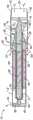
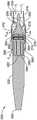
图1是根据本申请的具有径向马达以及径向和轴向轴承的微创血管内循环辅助泵组件的截面侧视图;1 is a cross-sectional side view of a minimally invasive endovascular circulation assist pump assembly with a radial motor and radial and axial bearings in accordance with the present application;
图2是图1的泵的透视图;Figure 2 is a perspective view of the pump of Figure 1;
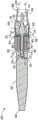
图3是根据本申请的具有径向马达的微创血管内循环辅助泵组件的截面侧视图,该径向马达具有混合流液压系统;3 is a cross-sectional side view of a minimally invasive endovascular circulation assist pump assembly with a radial motor having a mixed flow hydraulic system in accordance with the present application;
图4是图3的泵的透视图;Figure 4 is a perspective view of the pump of Figure 3;
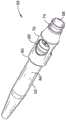
图5是根据本申请的具有轴向马达的微创血管内循环辅助泵组件的截面侧视图,该轴向马达具有混合流液压系统;5 is a cross-sectional side view of a minimally invasive endovascular circulation assist pump assembly with an axial motor having a mixed flow hydraulic system in accordance with the present application;
图6是图5的泵的透视图;Figure 6 is a perspective view of the pump of Figure 5;
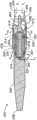
图7是根据本申请的具有轴向马达的替代性微创血管内循环辅助泵组件的截面侧视图,该轴向马达具有混合流液压系统;7 is a cross-sectional side view of an alternative minimally invasive endovascular circulation assist pump assembly with an axial motor having a mixed flow hydraulic system in accordance with the present application;
图8是图7的泵的透视图;Figure 8 is a perspective view of the pump of Figure 7;
图9是根据本申请的替代性的微创血管内循环辅助泵组件的截面侧视图,该组件具有带有混合流液压系统的双侧轴向马达;9 is a cross-sectional side view of an alternative minimally invasive endovascular circulation assist pump assembly having a dual-sided axial motor with a mixed flow hydraulic system in accordance with the present application;
图10是图9的泵的透视图;Figure 10 is a perspective view of the pump of Figure 9;
图11是根据本申请的具有密封径向马达的微创血管内循环辅助泵组件的截面侧视图,该密封径向马达具有混合流液压系统;11 is a cross-sectional side view of a minimally invasive endovascular circulation assist pump assembly with a sealed radial motor having a mixed flow hydraulic system in accordance with the present application;
图12是图11的泵的透视图。FIG. 12 is a perspective view of the pump of FIG. 11 .
具体实施方式Detailed ways
更具体地参考附图,出于说明的目的,本技术体现在图1至图12中大体示出的装置中。应当理解,该装置可以在配置和部件细节方面有所变化,并且在不脱离本文所公开的基本概念的前提下,该方法可以在特定步骤和顺序方面有所变化。图1至图12所示的装置示出了微型心脏辅助泵,该微型辅助泵被配置为通过减少暴露于血液的异物(例如转子/定子和泵壳体表面)的表面积来改善血液相容性,从而提高安全性。在最小化设计的同时,保持扭矩不变(以节约能量),从而维持血液持续流通并控制压力。血液相容性的关键因素是减少切应力和暴露时间。为了改善血液相容性,应减少其中之一或二者。这样,泵可以具有低的切应力,但是对那些应力的暴露时间会很长。Referring more particularly to the drawings, for purposes of illustration, the present technology is embodied in the apparatus generally shown in FIGS. 1-12 . It is to be understood that the apparatus may vary in configuration and detail of components and that the method may vary in the specific steps and order without departing from the basic concepts disclosed herein. The devices shown in Figures 1-12 illustrate a miniature cardiac assist pump configured to improve blood compatibility by reducing the surface area of foreign bodies exposed to blood (eg rotor/stator and pump housing surfaces) , thereby improving security. Keeping torque constant (to save energy) while minimizing design maintains continuous blood flow and pressure control. A key factor in hemocompatibility is reducing shear stress and exposure time. To improve blood compatibility, one or both should be reduced. In this way, the pump can have low shear stresses, but the exposure time to those stresses will be long.
首先参考图1和图2所示的实施方式。图1示出了根据本申请的具有径向马达以及径向和轴向轴承的微创血管内循环辅助泵组件10的截面侧视图。图2是图1的泵组件10的透视图。Reference is first made to the embodiments shown in FIGS. 1 and 2 . 1 shows a cross-sectional side view of a minimally invasive endovascular circulation assist
泵组件10包括具有第一端46和第二端48的泵壳体12、以及构造成可旋转地设置在壳体12内的转子14。这些部件按如下那样以特定方式相对于彼此构造。The
壳体12包括在第一端46处的轴向入口,该轴向入口通向构造成用于容纳转子14的叶轮16的第一圆柱形孔18。叶轮通常包括多个螺旋形扫掠叶片(helical sweepingblade)。壳体12还可包括耦接至内孔18的螺旋形定子(扩散器)叶片20。虽然图1中示出的这种叶轮叶片16和定子叶片20的具体结构和相对布置被认为是有益的使用,但是可以采用对于普通技术人员显而易见的其他结构配置。在这种结构中,转子轴45包括在定子叶片20之间旋转的毂。圆柱形孔18和叶轮16组合成为用于将血流Fi吸入到孔18中的泵室。The
壳体12具有第一部分30,该第一部分30从第一端46开始轴向地朝向壳体12的第二端48延伸,但未及于第二端48。壳体的第一部分30的直径大于壳体12的于第二端48处终止的其余部分的直径,从而第一部分30形成与圆柱形孔18连通并位于圆柱形孔18的远端处的环形开口22。环形开口22形成轴向定向的出口,用于令轴向的出口血流Fo从圆柱形孔或泵室18流出。The
转子16的细长轴45设置在与圆柱形孔18同心的第二圆柱形孔40内。圆柱形孔40的尺寸设置成使得它形成与转子轴45的外轴承表面配合的内轴承表面,该配合系通过这两个表面之间的轴颈轴承配合(journal bearing fit)实现。为了本说明书描述的目的,术语“圆柱形孔40”和“内轴承表面”可互换地使用。因此,圆柱形孔40和转子轴45的轴承表面形成流体动力轴颈轴承(hydrodynamic journal bearing),有时也称为“流体”轴承或“机械”轴承或轴衬。形成的流体动力轴承是转子轴轴承表面和内轴承表面之间的间隔的函数,其沿着转子轴45的至少大部分长度,包括让血液在轴承内润滑和流动的环形间隙或泄流路径32。The
在图1的运行模式所示的泵组件10的正常工作期间,转子14在壳体12内的旋转运动一般是通过磁力驱动的径向马达或致动器来实现的,该径向马达或致动器包括分别设置在转子轴45和壳体12的轴承表面内的转子磁体28和转子定子。实心转子轴45容纳与马达定子26相互作用的一个或多个转子磁体28。马达定子26包括导电线圈(未示出),该导电线圈适于通过导线耦接至电源(未示出),并且相对于转子磁体28而定位以形成磁通量间隙马达接口,从而在通过电源激活后进入的工作模式中,流过马达定子26线圈的电流产生磁通量场。该磁通量场跨越转子14和壳体12之间的磁通间隙(即泄流路径32)而延伸,并使转子磁体28移动得足以扭动转子14并使转子14在轴颈轴承间隙的圆柱形孔40内旋转。还应当理解的是,马达定子26线圈可以相对于转子磁体28轴向偏移,以形成转子轴45进入壳体的孔40中的轴向力或预载荷。During normal operation of the
当转子14在泵壳体12内旋转时,叶轮16从端部46处的轴向入口24向内抽吸血流Fi,使其进入由圆柱形孔18限定的泵室中。血流相对于转子轴45和圆柱形孔18、40的纵向轴线同轴地被引导到轴向入口24中。因此,血液的入口血流Fi的流动方向和血液的出口血流Fo的流动方向主要为轴向。在泵10位于循环系统的第一位置处的情况下,轴向入口24可耦接至套管的第一端(未示出),其中,出口血流Fo被分散到套管的第一端中,以用于将血液的出口血流分配到位于循环系统中的第二位置的套管的第二端。还可理解的是,如图1所示的血流的流动可以是反向的(例如,通过叶轮16的反向或叶轮叶片的相反定向),使得环形孔22是一输入,而在端部46的轴向口24是一输出。As
转子14的径向支撑是通过转子轴45的外轴承表面与泵壳体12的圆柱形孔40的内轴承表面之间的相对运动的作用而实现。这产生了流体动力径向或轴颈轴承。特别地,由转子14相对于内轴承表面的相对运动产生的流体动力推力是转子在圆柱形孔40内径向悬浮的主要或唯一来源。轴颈轴承的尺寸设计为形成环形间隙(泄流路径)32,该环形间隙是转子轴45的外径和孔40的内径的函数。在一优选实施例中,环形间隙的尺寸设计为在0.002英寸至0.003英寸之间。可以理解的是,图1的图像示出了针对泄流路径32的大得多的间隙(相对于其他部件尺寸),主要是出于示出泵10的流量特性的说明目的。The radial support of the
轴颈轴承结构有利地使剪应力最小化,令出口血流Fo和轴向入口血流Fi同时进行,促进了泄流流FL从孔40入口处的轴向泄流入口朝向后地流向转子14的半球形端部36并最终从径向口34流出。泄流流FL由转子14上的几何形状(即泵送凹槽)驱动。泄流路径流FL的方向可以基于转子14的几何形状而反转(与该实施例中所示的方向相反)。The journal bearing structure advantageously minimizes shear stress, allowing simultaneous outlet flow Fo and axial inlet flow Fi, promoting bleed flow FL from the axial bleed inlet at the entrance of bore 40 towards the rear towards
所有的配合表面优选地沿着连通的泄流路径32进行连续的相对运动。因此,所有这种紧密的间隙、低流动的表面利用运动而连续地被洗刷;如此,通过使诸如溶血和血栓形成的负面生理影响最小化,可以优化血液相容性。特别地,由于Fi>>FL,所以溶血作用降到最低。其他血液相容性因素,例如血管性血友病(von Willebrand)因子、血小板活化等,也可能受到积极影响。主动泄流泄流路径32通过移动部件而得以主动洗刷孔40内的裸露表面。这减轻了对于密封的需求,该密封通常会加剧血栓的形成,因此,本实施例提高了植入物的寿命。All mating surfaces preferably undergo continuous relative movement along the communicating
在一优选实施例中,转子轴45和圆柱形孔40的轴承表面以及在下面的各个实施例中公开的其他类似的轴承表面可以包括在穿过马达的泄流路径32中的径向轴承和/或半球形/轴向轴承中的一个或多个(均未示出),例如2016年5月2日提交的PCT国际申请PCT/US16/30445所示的那样,以为转子14提供额外的稳定性和流动特性。在一实施例中,转子轴45的圆柱形表面的一部分可以包括三瓣径向轴承,该三瓣径向轴承通常包括从基部直径部分(未示出)向外延伸的三个凸台(未示出)、以及从每个凸台过渡至基部直径部分的锥形部(未示出)。In a preferred embodiment, the bearing surfaces of the
转子14还可以包括设置在转子14的半球形端部36处的带凹槽的半球形推力轴承(未示出)。在一种结构中,轴向推力轴承包括三个扫掠渐细的(swept-tapered)凹槽(未示出)。转子端部38的推力轴承接口与杯形内孔表面38构造成提供压力差和相应的泵送机构以促进流动通过泄流路径32。凹槽以浅-深-浅即在转子中心附近最深的配置从转子中心向外(径向)扫过。推力轴承会形成一个低压区域,该低压区域在深度从浅到深的过渡过程中在末端最小,而在凹槽出口处最大,从而提供了显着的径向稳定性。该压力产生轴向分布的推力,从而促进流入泄流路径32的流动,同时还同样地提供径向稳定性。The
还应当理解的是,半球形推力轴承和/或径向轴承也可以构造成使泄流路径32中的血流FL的流动反向,使得血液进入径向口34并在泄流路径32内逆行流动以从孔40朝向壳体的前端46流出。It should also be appreciated that hemispherical thrust bearings and/or radial bearings may also be configured to reverse the flow of blood flow FL in the
可以包含径向台阶42,用以支撑套管(未示出)或其他导管的联接。
接下来参考图3和图4中所示的实施例。图3示出了根据本申请的具有径向马达的微创血管内循环辅助泵组件50的截面侧视图,该径向马达具有混合流液压系统。图4是图3的泵组件50的透视图。Reference is next made to the embodiments shown in FIGS. 3 and 4 . 3 shows a cross-sectional side view of a minimally invasive endovascular circulation assist
泵组件50包括具有第一端86和第二端88的泵壳体52,以及以及构造成可旋转地设置在壳体52内的转子54。这些部件按如下那样以特定方式相对于彼此构造。The
壳体52包括在端部86处的轴向入口,该轴向入口通向构造成用于容纳转子54的叶轮56的中心孔58。叶轮56通常包括多个螺旋形扫掠叶片。不同于图1所示的实施例,泵组件50包含的混合流液压系统仅具有转子叶片,即没有定子叶片。虽然图3中示出的这种叶轮叶片56的具体结构和相对布置被认为是有益的使用,但是可以采用对于普通技术人员显而易见的其他结构配置。在这种结构中,孔58具有从端部86到叶轮叶片56的逐渐增大的横截面或直径。中心孔58和叶轮56组合成为用于将血流Fi吸入到中心孔58中的泵室。The
壳体52具有第一部分70,该第一部分70从端部86开始轴向地朝向壳体52的端部88延伸,但未及于该端部88。壳体的第一部分70延伸终止于远端处的直径比壳体52的其余部分的直径大,从而第一部分70形成与中心孔58连通并位于中心孔58的远端处的环形开口60。环形开口60形成轴向定向的出口,用于令轴向的出口血流FOA从圆柱形孔或泵室58流出。此外,血流FOR经由多个径向口62从中心孔58径向向外流出。出于探讨的目的,“径向口”在本文中定义为相对于流动方向具有至少径向分量的端口。图3和图4中示出的泵50的结构具有在壳体52中的3个径向口62,但是,应当理解,该径向口的数量可以是任意的。The
与叶轮56相对的转子54包括杯锥状轴承表面82和转子轴64,该转子轴64构造成设置在圆柱形孔76内。圆柱形孔76的尺寸设置成形成与转子轴64的外轴承表面配合的内轴承表面,该配合系通过这两个表面之间的轴颈轴承配合实现。因此,圆柱形孔76和转子轴64的轴承表面形成流体动力轴颈轴承。所形成的流体动力轴承是转子轴轴承表面与内轴承表面之间的间隔的函数,其沿着转子轴64的至少大部分长度,包括让血液在轴承内润滑和流动的环形间隙或泄流路径72。泄流路径72从形成于转子54的杯锥状表面82与壳体52的相对锥形表面80之间的锥形轴承入口开始沿着转子轴64/圆柱形孔76接口的长度延伸并终止于径向出口84。The
在图3的运行模式所示的泵组件50的正常工作期间,转子54在壳体52内的旋转运动通常是通过磁力驱动的径向马达或致动器来实现的,该径向马达或致动器包括分别设置在转子轴64的轴承表面和壳体52的轴承表面内的转子磁体65和转子定子66。实心转子轴64容纳与马达定子66相互作用的一个或多个转子磁体。马达定子66包括导电线圈(未示出),该导电线圈适于通过导线耦合至电源(未示出),并相对于转子磁体而定位以形成磁通间隙马达接口,从而在通过电源激活后进入的工作模式中,流过马达定子66线圈的电流产生磁通量场,该磁通量场跨越转子54和壳体52之间的磁通间隙(即泄流路径72)而延伸,并使转子磁体移动得足以扭动转子54并使转子54在轴颈轴承间隙圆柱形孔76内旋转。还应当理解,马达定子线圈66可以相对于转子磁体轴向偏移,以形成转子轴64进入壳体的孔76中的轴向力或预载荷。During normal operation of the
当转子54在泵壳体52内旋转时,叶轮56从端部86处的轴向入口向内抽吸血流Fi,使其进入由中心孔58限定的泵室中。血流相对于转子轴64和圆柱形孔76的纵向轴线同轴地被引导到轴向端口。血流的入口血流Fi的流动方向和血流的出口血流FOA的方向主要是轴向的,而径向出口血流FOR至少具有显着的径向分量。在泵50位于循环系统的第一位置处时,端部86处的轴向端口可以耦接至套管的第一端(未示出),其中输出的血流F0 被分散到套管的第一端中,以用于将血液的出口血流分配到位于循环系统的第二位置的套管的第二端。还可理解的是,如图3所示的血流的流动可以是反向的(例如,通过叶轮56的反向或叶轮叶片的相反定向),使得环形孔60和端口62是输入端,而在端部86的轴向口是输出端。As
转子54的径向支撑是通过锥形轴承以及转子轴64的外轴承表面与圆柱形孔76的内轴承表面之间的相对运动的作用而实现。这产生了流体动力径向或轴颈轴承。特别地,由转子54相对于内轴承表面的相对运动产生的流体动力推力是转子在圆柱形孔76内的径向悬挂的主要或唯一来源。轴颈轴承的尺寸设计为形成在转子轴64的外径和孔76的内径之间的环形间隙72。在一优选实施例中,环形间隙的尺寸设计为在0.002英寸至0.003英寸之间。Radial support of the
泄流流FL由转子54上的几何形状(即泵送凹槽)驱动。泄流路径流FL的方向可以基于转子54的几何形状而反向(与该实施例中所示的方向相反)。The bleed flow FL is driven by the geometry on the rotor 54 (ie the pumping grooves). The direction of the bleed path flow FL may be reversed (opposite the direction shown in this embodiment) based on the geometry of the
所有的配合表面优选地沿着连通的路径进行连续的相对运动。所有这种沿着泄流路径72的紧密的间隙、低流动的表面利用运动而被连续地冲洗,并且由于Fi>>FL,所以溶血作用和血栓形成或其他负面的生理影响可以降到最低。主动泄流流动路径72通过移动部件而得以主动清洗孔76和锥形轴承内的暴露表面。All mating surfaces preferably undergo continuous relative movement along a communicating path. All such tight clearance, low flow surfaces along
在一优选实施例中,转子轴64的轴承表面和圆柱形孔76的轴承表面可以包括在穿过马达的泄流路径72内的径向轴承(未示出)和锥形流体动力轴承,例如2016年5月2日提交的PCT国际申请PCT/US16/30445所示的那样,以便为转子54提供额外的稳定性和流动特性。在一实施例中,转子轴64的圆柱形表面的一部分可以包括三瓣径向轴承,该三瓣径向轴承通常包括从基部直径部分(未示出)向外延伸的三个凸台(未示出)、以及从每个凸台过渡至基部直径部分的锥形部(未示出)。In a preferred embodiment, the bearing surfaces of the
转子54还可包括锥形推力轴承,其通过转子54的锥形表面82和壳体52的锥形表面80形成。在这种结构中,轴向推力轴承包括三个纵向定向的凹槽(未显示),这些凹槽从轴64径向向外横向延伸。推力轴承构造成提供压力差和相应的泵送机构来促进流动通过泄流路径72。锥形轴承与半球形轴承的相似之处在于,它可以通过一组凹槽/部件产生径向力和轴向力/压力。在一些实施例中,锥形轴向轴承设计可包括替代纵向槽的渐细形凹槽(未示出),或者除了纵向槽之外还可具有该渐细形凹槽。The
端部86处也可以具有径向凸缘74,用以支撑套管(未示出)或其他导管的联接。There may also be
接下来参考图5和图6所示的实施例。图5示出了根据本申请的具有轴向马达的微创血管内循环辅助泵组件100的截面侧视图,该轴向马达具有混合流液压系统。图6是图5的泵组件100的透视图。图5和图6的轴向马达的构造使得通常在径向马达和内部轴颈轴承的构造中存在的轴向长度得以减小。Reference is next made to the embodiments shown in FIGS. 5 and 6 . 5 shows a cross-sectional side view of a minimally invasive endovascular circulation assist
泵组件100包括具有第一端136和第二端138的泵壳体102、以及构造成可旋转地设置在壳体102内的转子104。这些部件按如下那样以特定方式相对于彼此构造。The
壳体102包括在端部136处的轴向入口,该轴向入口通向构造成用于容纳转子104的叶轮106的中心孔108。叶轮106通常包括多个螺旋形扫掠叶片。不同于图1所示的实施例,泵组件100包括仅具有转子叶片的混合流液压系统。虽然图5中示出的这种叶轮叶片106的具体结构和相对布置被认为是有益的使用,但是可以采用对于普通技术人员显而易见的其他结构配置。在这种结构中,孔108具有从端部136到叶轮叶片106的逐渐增大的横截面或直径。中心孔108和叶轮106组合成为泵室,用于将血流Fi抽吸到中心孔108中。The
壳体102具有第一部分120,该第一部分120从端部136开始轴向地朝着壳体102的端部138延伸,但未及于该端部138。壳体的第一部分120延伸终止于远端处的直径比壳体102的其余部分的直径大,使得第一部分120形成与中心孔108连通并位于中心孔108的远端处的环形开口110。环形开口110形成轴向定向的出口,用于令轴向的出口血流FOA从圆柱形孔或泵室108流出。此外,血流FOR经由多个径向口112从中心孔108径向向外流出。图5和图6中示出的泵100的结构具有在壳体102中的3个径向口112,但是,应当理解,该径向口的数量可以是任意的。The
与叶轮106相对的转子104包括杯锥状轴承表面122,该杯锥状轴承表面122构造成与壳体102的锥形表面124相配合以形成流体动力轴承,该配合系通过这两个表面之间的轴颈轴承配合而实现。所形成的流体动力轴承是与锥形表面124相配合的杯锥状轴承表面122之间的间隔的函数,其包括让血液在轴承内润滑和流动的间隙或泄流路径126。The
在如图5的运行模式中所示的泵组件100的正常工作期间,转子102在壳体102内的旋转运动通常是通过磁力驱动的轴向马达或致动器来实现的,该轴向马达或致动器包括分别设置在转子104的轴承表面和壳体102的轴承表面内的一个或多个转子磁体114和转子定子116。马达定子116包括导电线圈(未示出),该导电线圈适于经由导线耦接至电源(未示出),并且相对于转子磁体而定位以形成磁通量间隙马达接口,从而在通过电源激活后进入的工作模式中,流过马达定子116线圈的电流产生磁通量场,该磁通量场跨越转子104和壳体102之间的磁通量间隙(即泄流路径126)而延伸,并使转子磁体移动得足以扭动转子104并使转子104在轴颈轴承间隙内旋转。During normal operation of the
当转子104在泵壳体102中旋转时,叶轮106从端部136处的轴向入口向内抽吸血流Fi,使其进入由中心孔108限定的泵室。血流相对于转子104的纵向或旋转轴线同轴地被引导到轴向端口。血流的入口血流Fi的流动方向和血流的出口血流FOA的流动方向主要是轴向的,而径向出口血流FOR至少具有至少显着的径向分量。在泵100位于循环系统的第一位置处时,端部136处的轴向端口可以耦接至套管的第一端(未示出),其中,输出的血流F0被分散到套管的第一端中,以将输出的血流分配到位于循环系统的第二位置的套管的第二端。还可理解的是,如图5所示的血流的流动方向可以是反向的(例如,通过叶轮106的反向或叶轮叶片的相反定向),使得环形孔110和端口112是输入,而在端部136的轴向端口是输出。As
转子104的径向支撑是通过轴承表面122和124之间的流体动力锥形轴承以及相对运动的作用而实现。这产生了流体动力径向或轴颈轴承。特别地,由转子104相对于内轴承表面的相对运动产生的流体动力推力是转子在中心孔108内的径向悬挂的主要或唯一来源。轴颈轴承的尺寸设计为形成间隙或泄流路径126,该间隙或泄流路径的尺寸在0.002英寸至0.003英寸之间。Radial support of the
泄流路径126中的泄流流由转子104或壳体102上的几何形状(即泵送凹槽)驱动。泄流流在泄流路径中的流动方向可以基于转子104的几何形状反向。所有这种沿着泄流路径126的紧密间隙、低流动的表面利用运动而被连续地冲洗,由于主动泄流流动路径126通过移动部件可以主动冲洗暴露的表面,因此溶血和血栓形成可以减至最小。The bleed flow in the
在一优选实施例中,如2016年5月2日提交的PCT国际申请PCT/US16/30445中所提供的那样,轴承表面包括在穿过马达的泄流路径126内的锥形流体动力轴承,以便为转子104提供附加的稳定性和流动特性。锥形推力轴承是通过转子104和壳体102的锥形表面122、124而形成。在这种结构中,轴向推力轴承包括从转子104的中心径向向外横向延伸的三个纵向定向的凹槽(未显示)。推力轴承构造成提供压力差和相应的泵送机构来促进流动通过泄流路径126。锥形轴承与半球形轴承的相似之处在于,它可以通过一组凹槽/部件产生径向力和轴向力/压力。在一些实施例中,锥形轴向轴承设计可包括替代纵向槽的渐细形凹槽(未示出),或者除了纵向槽之外还可具有该渐细形凹槽。In a preferred embodiment, as provided in PCT International Application PCT/US16/30445, filed May 2, 2016, the bearing surface comprises a tapered hydrodynamic bearing within the
端部136处也可以具有径向凸缘130,用以支撑套管(未示出)或其他导管的联接。There may also be
接下来参考图7和图8所示的实施例。图7示出了根据本申请的另一具有轴向马达的微创血管内循环辅助泵组件150的截面侧视图,该轴向马达具有混合流液压系统。图8是图7的泵组件150的透视图。Reference is next made to the embodiments shown in FIGS. 7 and 8 . 7 shows a cross-sectional side view of another minimally invasive intravascular circulation assist
泵组件150包括具有第一端186和第二端188的泵壳体152、以及构造成可旋转地设置在壳体152内的转子154。这些部件按如下那样以特定方式相对于彼此构造。The
壳体152包括在端部186处的轴向入口,该轴向入口通向构造成用于容纳转子154的叶轮156的中心孔158。叶轮156通常包括多个螺旋形扫掠叶片。不同于图1所示的实施例,泵组件150包括仅具有转子叶片的混合流液压系统。虽然图7中示出的这种叶轮叶片106的具体结构和相对布置被认为是有益的使用,但是可以采用对于普通技术人员显而易见的其他结构配置。在这种结构中,孔158具有从端部186到叶轮叶片106的逐渐增大的横截面或直径。中心孔158和叶轮156组合成为用于将血流Fi抽吸到中心孔158中的泵室。The
壳体152具有从端部186开始的第一部分170,其朝着壳体152的端部188轴向延伸但未及于壳体152的端部188。壳体的第一部分170延伸终止于远端处的直径比壳体152的其余部分的直径还大,使得第一部分170形成与中心孔108连通并位于中心孔108的远端处的环形开口160。环形开口160形成轴向定向的出口,用于令轴向的出口血流FOA从圆柱形孔或泵室158流出。此外,血流FOR经由多个径向口162从中心孔158径向向外流出。图7和图8中示出的泵150的结构具有在壳体152中具有3个径向口162,但是,可以理解,该径向口的数量可以是任意的。
与叶轮156相对的转子154包括:构造成与壳体152的锥形表面180紧密配合的杯锥状轴承表面182,以及通过轴颈轴承配合方式与壳体的圆柱轴176周围相配合的圆柱形孔174,其中该轴颈轴承配合发生于相应的表面以形成流体动力轴颈轴承。所形成的流体动力轴承是构造成与锥形表面180配合的杯锥状轴承表面182和装配在圆柱轴176周围的圆柱形孔174之间的间距的函数,其形成让血液在轴承内润滑和流动的连续间隙或泄流路径172。The
在如图7的运行模式中所示的泵组件150的正常工作期间,转子154在壳体152内的旋转运动通常是通过磁力驱动的轴向马达或致动器来实现的,该轴向马达或致动器包括分别设置在转子154的轴承表面和壳体152的轴承表面内的一个或多个转子磁体164和转子定子166。马达定子166包括导电线圈(未示出),该导电线圈适于经由导线耦合至电源(未示出),并且相对于转子磁体而定位以形成磁通量间隙马达接口,从而在通过电源激活后进入的工作模式中,流过马达定子166线圈的电流会产生磁通量场,该磁通量场跨越转子154和壳体152之间的磁通量间隙(即泄流路径172)延伸,并使转子磁体移动得足以扭动转子154并使转子154在轴颈轴承间隙内旋转。During normal operation of the
当转子154在泵壳体152内旋转时,叶轮156从端部186处的轴向入口向内抽吸血流Fi,使其进入由中心孔158限定的泵室。血流相对于转子154的纵向或旋转轴线同轴地被引导到轴向端口。血流的入口血流Fi的流动方向和血流的出口血流FOA的流动方向主要是轴向的,而径向出口血流FOR至少具有显着的轴向分量。在泵150位于循环系统的第一位置处时,端部186处的轴向端口可以耦接到套管的第一端(未示出),其中,输出的血流F0被分散到套管的第一端中以将输出的血流分配到位于循环系统第二位置的套管第二端。还可理解的是,如图7所示的血流的流动方向可以是反向的(例如,通过叶轮156的反向或叶轮叶片的相反定向),使得环形孔160和端口162是输入,而在端部186的轴向端口是输出。As
转子154的径向支撑是通过轴承表面122和124以及壳体轴176的外部轴承表面和圆柱形孔174的内部轴承表面之间的流体动力锥形轴承以及相对运动的作用而实现。这产生了流体动力径向或轴颈轴承。特别地,由转子154相对于内轴承表面的相对运动产生的流体动力推力是转子在壳体轴176上的径向悬挂的主要或唯一来源。轴颈轴承的尺寸设计为形成间隙或泄流路径172,该间隙或泄流路径的尺寸在0.002英寸至0.003英寸之间。Radial support of
泄流路径172内的泄流流由转子154或壳体152上的几何形状(即,泵送凹槽)驱动。泄流流在泄流路径中的流动方向可以基于转子154的几何形状而反向。所有这种沿着泄流路径172的紧密间隙、低流动的表面利用运动而被连续地清洗,由于主动泄流流动路径172通过移动部件可以主动地冲洗暴露的表面,因此溶血和血栓形成可以减至最小。The bleed flow within the
在一优选实施例中,如2016年5月2日提交的PCT国际申请PCT/US16/30445中所提供的那样,轴承表面包括在穿过马达的泄流路径172内的径向轴承(未示出)和锥形流体动力轴承,以便为转子154提供额外的稳定性和流动特性。锥形推力轴承是通过转子154和壳体152的锥形表面182、180而形成。在这种结构中,轴向推力轴承包括从转子154的中心径向向外横向延伸的三个纵向定位的凹槽(未显示)。推力轴承构造成提供压力差和相应的泵送机构来促进流动通过泄流路径172。锥形轴承与半球形轴承的相似之处在于它可以通过一组凹槽/部件同时产生径向和轴向力/压力。在一些实施例中,锥形轴向轴承设计可包括替代纵向槽的渐细形凹槽(未示出),或者除了纵向槽之外还可具有该渐细形凹槽。In a preferred embodiment, as provided in PCT International Application PCT/US16/30445, filed on May 2, 2016, the bearing surfaces include radial bearings (not shown) within the
端部186处也可以具有径向凸缘184,用以支撑套管(未示出)或其他导管的联接。There may also be
接下来参考图9和图10所示的实施例。图9是根据本申请的具有双侧轴向马达的微创血管内循环辅助泵组件200的截面侧视图,该双侧轴向马达采用混合流液压系统。图10是图9的泵200的透视图。Reference is next made to the embodiments shown in FIGS. 9 and 10 . 9 is a cross-sectional side view of a minimally invasive endovascular circulation assist
泵组件200包括具有第一端236和第二端238的泵壳体202,以及构造成可旋转地设置在壳体202内的转子204。这些部件按如下那样以特定方式相对于彼此构造。The
壳体202在端部236处包括轴向入口,该轴向入口通向构造成用于容纳转子204的叶轮206中心孔208。叶轮206通常包括多个螺旋形扫掠叶片。泵组件200包括仅具有转子叶片的混流液压系统。虽然图9中示出的这种叶轮叶片206的具体结构和相对布置被认为是有益的使用,但是可以采用对于普通技术人员显而易见的其他结构配置。在这种结构中,孔208具有从端部236到叶轮叶片206的逐渐增大的横截面或直径。中心孔208和叶轮206成为用于将血流Fi吸入中心孔208的泵室中。The
壳体202具有从端部136开始的第一部分220,其朝着壳体202的端部238轴向延伸,但未及于该端部。壳体的第一部分220延伸终止于远端处的直径比壳体202的其余部分的直径还大,使得第一部分220形成与中心孔208连通并位于中心孔208的远端处的环形开口210。环形开口210形成轴向定向的出口,用于令轴向的出口血流FOA从圆柱形孔或泵室208流出。此外,血流FOR经由多个径向口212从中心孔208径向向外流出。图9和图10中示出的泵200的结构具有在壳体202中具有3个径向口212,但是,可以理解,该径向口的数量可以是任意的。
与叶轮206相对的转子204包括杯锥状轴承230,类似于图3所示的杯锥状表面80、82。转子轴224设置在杯锥状轴承230的轴承远端,并位于圆柱形孔226内。圆柱形孔226的尺寸设计为使得其形成与转子轴224的外轴承表面配合的内轴承表面,该配合系通过这两个表面之间的轴颈轴承配合而实现,如上所述。第二相对的杯锥状轴承231设置在轴224上与第一杯锥状轴承230相对的一侧。在一优选实施例中,泄流路径232和相应的流体动力轴承通过三个轴承表面中的两个而形成,该三个轴承表面包括锥形轴承230、231以及由轴224/圆柱形孔226的边界(interface)形成的圆柱轴承。例如,两个锥形轴承边界230、231可以是流体动力轴承,其中轴224/圆柱形孔226的边界是张口更大的间隙,从而可以形成非流体动力的方式。可替代地,锥形轴承边界230、231之一可以是流体动力轴承,也可以是流体动力轴承,以及轴224/圆柱形孔226边界。The
所形成的流体动力轴承是转子轴轴承表面和内轴承表面之间的间距(例如圆柱形孔226和壳体202的相对的锥形表面)和一定的间隙的函数,以在轴承内润滑和流动。泄流路径232从形成于锥形轴承230上的锥形轴承入口开始沿着转子轴224/圆柱形孔226的的长度延伸,穿过第二锥形轴承231,并终止于径向出口234。在工作期间,沿着泄流路径232的所有低流动表面利用运动而被连续地冲洗,并且由于Fi>>FL,所以溶血和血栓形成可以降到最低。主动泄流流动路径232通过移动部件而得以主动清洗孔232和锥形轴承内的暴露表面。The resulting hydrodynamic bearing is a function of the spacing between the rotor shaft bearing surface and the inner bearing surface (eg, the
如图9的运行模式中所示的泵组件200的正常工作期间,转子204在壳体202内的旋转运动通常是通过磁力驱动的双侧轴向马达或致动器来实现。双侧轴向马达包括设置在转子204的两侧且平行于锥形轴承230/231边界的转子磁体214,以及设置在壳体202的轴承表面内的转子定子216。马达定子216包括导电线圈(未示出),该导电线圈适于经由导线耦合至电源(未示出),并且相对于转子磁体而定位以形成磁通量间隙马达接口,从而在通过电源激活后进入的工作模式中,流过马达定子216线圈的电流产生磁通量场,该磁通量场跨越转子204和壳体202之间的磁通间隙(即泄流路径232)延伸,并且使转子磁体移动得足以扭动转子204并使转子204在轴颈轴承间隙内旋转。During normal operation of the
当转子204在泵壳体202内旋转时,叶轮206从端部236处的轴向入口向内抽吸血流Fi,使其进入由中心孔208限定的泵室。血流相对于转子轴224和圆柱形孔226的纵轴同轴地进入轴向端口。血流的入口血流Fi的流动方向和血流的出口血流FOA的流动方向主要是轴向的,而径向出口血流FOR至少具有显着的轴向分量。在泵200位于循环系统的第一位置处时,端部236处的轴向端口可耦接到套管的第一端(未示出),其中,输出的血流F0被分散到套管的第一端中,以将输出的血流分配到位于循环系统中第二位置的套管的第二端。还可理解的是,如图9所示的血流的流动方向可以是反向的(例如,通过叶轮206倒转方向或叶轮叶片的相反定向),使得环形孔210和端口212是输入,而在端部236的轴向端口是输出。As
泄流流FL由转子204上的几何形状(即泵送凹槽)驱动。泄流路径流FL的方向可以基于转子204的几何形状而反向(与该实施例中所示的方向相反)。The bleed flow FL is driven by the geometry on the rotor 204 (ie the pumping grooves). The direction of the bleed path flow FL may be reversed (opposite the direction shown in this embodiment) based on the geometry of the
在一优选实施例中,如2016年5月2日提交的PCT国际申请号PCT/US16/30445所示的那样,转子轴224的轴承表面和圆柱形孔226的轴承表面可以包括在穿过马达的泄流路径232内的径向轴承(未示出)和锥形流体动力轴承,以便为转子204提供额外的稳定性和流动特性。在一实施例中,转子轴224的圆柱形表面的一部分可以包括三瓣径向轴承,该三瓣径向轴承通常包括从基部直径部分(未示出)向外延伸的三个基部(未示出)以及从每个凸台过渡至基部直径部分的锥形部(未示出)。In a preferred embodiment, as shown in PCT International Application No. PCT/US16/30445, filed May 2, 2016, the bearing surface of the
转子204还可包括经由锥形表面230、231形成的锥形推力轴承。在此结构中,轴向推力轴承包括三个纵向定向的凹槽(未显示),这些凹槽从轴224径向向外横向延伸。推力轴承构造成提供压力差和相应的泵送机构来促进流动通过泄流路径232。锥形轴承与半球形轴承的相似之处在于,它可以通过一组凹槽/部件产生径向力和轴向力/压力。在一些实施例中,锥形轴向轴承设计可包括替代纵向槽的渐细形凹槽(未示出),或者除了纵向槽之外还可具有该渐细形凹槽。The
端部236处也可以具有径向凸缘222,用以支撑套管(未示出)或其他导管的联接。There may also be
接下来参考图11和图12中所示的实施例。图11是根据本申请的具有密封径向马达的微创血管内循环辅助泵组件250的截面侧视图,该密封径向马达具有混合流液压系统。图12是图11的泵250的透视图。Reference is next made to the embodiments shown in FIGS. 11 and 12 . 11 is a cross-sectional side view of a minimally invasive endovascular circulation assist
泵组件250包括具有第一端286和第二端288的泵壳体252,以及构造成可旋转地设置在壳体252内的转子254。这些部件按如下那样以特定方式相对于彼此构造。The
壳体252包括在端部286处的轴向入口,该轴向入口通向构造成用于容纳转子254的叶轮256的中心孔258。叶轮256通常包括多个螺旋形扫掠叶片。泵组件250包括仅具有转子叶片的混流液压系统。尽管图11中示出的这种叶轮叶片256的具体结构和相对布置被认为是有益的使用,但是可以采用对于普通技术人员显而易见的其他结构配置。在这种结构中,孔258具有从端部286到叶轮叶片256的逐渐增大的横截面或直径。中心孔258和叶轮256组合成为用于将血流Fi吸入中心孔258的泵室。The
壳体252具有从端部286开始的第一部分280,其朝着壳体252的端部288轴向延伸,但未及于壳体252的端部288。壳体的第一部分280延伸终止于远端处的直径比壳体252的其余部分的直径还大,使得第一部分280形成与中心孔258连通并位于中心孔258的远端处的环形开口260。环形开口260形成轴向定向的出口,用于令轴向的出口血流FOA从圆柱形孔或泵室258流出。此外,血流FOR经由多个径向口272从中心孔258径向向外流出。图11和图12中示出的泵250的结构具有在壳体252中的3个径向口272,但可以理解的是,该径向口的数量可以是任意的。
与叶轮256相对的转子254包括平的轴承表面284,其构造成与壳体252的平的轴承表面282相配合,该配合系通过这两个表面之间的轴颈轴承配合而实现,以形成流体动力轴颈轴承。所形成的流体动力轴承是相配合的平的表面282、284之间的间隔的函数,其包括用于让血流在轴承中润滑并流动的间隙或泄流路径274。The
在图11的运行模式中所示的泵组件250的正常运行期间,壳体254内的转子254的旋转运动通常是通过磁力驱动的密封径向马达或致动器来实现,该马达或致动器包括驱动内部转子262的转子定子266,该内部转子262具有全部设置在密封腔264内的一个或多个磁体268。马达定子266包括导电线圈(未示出),该导电线圈适于经由导线耦合至电源(未示出)。内部转子的运动以及由此产生的磁体268的运动产生了与转子254中的相应磁体270相耦合的旋转磁场,其中,磁场跨越转子254和壳体252之间的间隙(即泄流路径275)延伸,使转子磁体270移动得足以扭动转子254并使转子254旋转。During normal operation of the
当转子254在泵壳体252内旋转时,叶轮256从端部286的轴向入口向内抽吸血流Fi,使其进入由中心孔258限定的泵室。血流相对于转子254的纵向或旋转轴线同轴地流入轴向端口。血流的入口血流Fi的流动方向和血流的出口血流FOA的流动方向主要是轴向的,而径向出口流FOR至少具有显着的轴向分量。在泵250位于循环系统的第一位置处,端部286处的轴向端口可以耦接到套管的第一端(未示出),其中,输出的血流F0被分散到套管的第一端中,以将输出的血流分散到循环系统第二位置的套管第二端。还可理解的是,如图11所示的血流的流动方向可以是反向的(例如通过叶轮256倒转方向或叶轮叶片的相反定向),使得环形孔260和端口272是输入,而在端部286的轴向端口是输出。As
转子254首先由穿过泄流路径274的磁力耦合支撑,这导致了被流体动压轴承推压的磁性“预载荷”。前述平的推力轴承上的载荷随着转子254速度的变化而变化(其中,转子速度越快,转子254越会倾向移动远离磁力耦合)。不过,转子的轴向平移会受到叶轮叶片256和护罩280的相互作用和几何约束的限制。其中,相对的表面可以通过材料选择和几何形状来进行优化,以减少机械磨损。例如,叶片256的外在结构形状可以实现为锥形的几何形状,以在紧密接近时产生流体动力轴承效果。上文针对泵组件250详述的几何和流体动力相互作用也可存在于图5和图7的泵组件100、150中或用于图5和图7的泵组件100、150,其中轴向的预载荷由混合的轴向/径向磁力耦合确定。The
泄流路径274内的泄流流由转子254或壳体252上的几何形状(即,泵送凹槽)驱动。泄流路径流动的方向可以基于转子254的几何形状而反向。所有这种沿着泄流路径274进行的紧密间隙、低流动的表面利用运动而被连续冲洗,由于主动泄流流动路径274通过移动部件可以主动冲洗暴露的表面,因此溶血和血栓形成可以减至最小。Drain flow within
在一优选实施例中,如2016年5月2日提交的PCT国际申请PCT/US16/30445中所提供的那样,轴承表面包括在穿过马达的泄流路径274内的平的流体动力轴承,以便为转子254提供额外的稳定性和流动特性。转子254的平的端部282处可设置平的轴向推力轴承。在一种结构中,轴向推力轴承包括朝着扁平端部282横向延伸的三个纵向扫掠渐细的凹槽。推力轴承构造成提供压力差和相应的泵送机制以促进流动通过泄流路径274。平的轴承还可以得益于两个轴承部件组——一个径向轴承和一个轴向轴承。在一些实施例中,推力轴承设计可包括替代纵向槽的渐细形凹槽(未示出),或者除了纵向槽之外还可具有该渐细形凹槽。In a preferred embodiment, as provided in PCT International Application PCT/US16/30445, filed May 2, 2016, the bearing surface comprises a flat hydrodynamic bearing within the
端部286也可以具有径向凸缘276,用以支撑套管(未示出)或其他导管的联接。
柔性套管(未示出)可以附接到泵10、50、100、150、200和250中的任何一个的泵体或壳体。在这样的结构中,泵将从套管的第一端内抽吸输入的血流Fi,套管的第二端位于循环系统中的不同位置。A flexible sleeve (not shown) may be attached to the pump body or housing of any of the
可以理解的是,基于对本申请的全面回顾,通过如本文所述的那样,对于本领域的普通技术人员而言,显而易见地,本申请的各种装置/泵实施例能够显着地有益于微创和低创插入方法的目的。本申请公开了用于低创外科手术植入的两种特别有益的方法,但并没有限制,并且其包括:1)无血管吻合术的插入,以及2)有血管吻合术的插入。It will be appreciated that, based on a comprehensive review of the present application, it will be apparent to those of ordinary skill in the art, as described herein, that the various device/pump embodiments of the present application can significantly benefit minimally invasive and the purpose of a low-invasive insertion method. The present application discloses, but is not limiting of, two particularly beneficial methods for low-invasive surgical implantation, and includes: 1) insertion without vascular anastomosis, and 2) insertion with vascular anastomosis.
在允许实施VAD(例如LV/LA或RV/RA)的范围内,微创插入被认为具有特别的优势,无需胸廓切开术或心肺旁路。中央血管通路被认为是特别有益的,因为它是通过周围血管通路来实现的,例如使用荧光镜引导,以放置血管内泵或专用插管。To the extent that a VAD (eg, LV/LA or RV/RA) is permitted, minimally invasive insertion is considered to be of particular advantage, without the need for a thoracotomy or cardiopulmonary bypass. Central vascular access is considered particularly beneficial because it is achieved through peripheral vascular access, such as using fluoroscopic guidance, to place intravascular pumps or specialized cannulas.
低创插入对于将LVAD置于有限的手术切口且无心肺旁路的情况而言被认为是特别有益的。此外,消除对血管吻合术的需要的方法被认为是非常有利的,并且根据本发明的某些实施例而被有利地实现。插入方法利用胸腔镜技术的,进一步简化了手术,并且也通过某些本申请的实施例而实现。Low-invasive insertion is considered to be particularly beneficial in situations where the LVAD is placed in a limited surgical incision without cardiopulmonary bypass. Furthermore, a method that eliminates the need for vascular anastomosis is considered to be highly advantageous, and is advantageously implemented in accordance with certain embodiments of the present invention. The insertion method utilizes thoracoscopic techniques, further simplifying the procedure, and is also achieved by certain embodiments of the present application.
LVADS的微创安置通常被认为主要属于介入性心脏病学家的领域(但是显然地,其他受过充分训练和有能力的医师也可以实施本发明)。本实施例中的某些实施例提供了针对这种介入性医师使用的适应性,特别是因为这样的装置一般允许以下至少一种,并且优选地一种或全部以上:1)用于实现非开胸的血管通路的简单装置,2)适于插入外周动脉的小型套管系统和微型泵,3)适于在胸壁上皮下植入的小型泵,以及4)能够在非卧床环境中可靠地运行数月至数年的泵。提供能够在扩展的非卧床中可靠地操作的LVAD的微创或低创植入的能力是本申请中的某些实施例所呈现的特别益处,并且以前通过先前公开或使用的装置和方法是不可能实现的。Minimally invasive placement of LVADS is generally considered to be primarily within the field of interventional cardiologists (although obviously other well-trained and competent physicians may also practice the present invention). Certain of the present embodiments provide adaptability for such interventional physician use, particularly since such devices generally allow at least one, and preferably one or all of the following: 1) for use in achieving non- A simple device for thoracotomy vascular access, 2) a small cannula system and micropump suitable for insertion into peripheral arteries, 3) a small pump suitable for subepithelial implantation in the chest wall, and 4) capable of reliable operation in an ambulatory setting Pumps that run for months to years. The ability to provide minimally invasive or low-invasive implantation of LVADs that can operate reliably in extended ambulatory settings is a particular benefit presented by certain embodiments in this application, and previously disclosed or used through previously disclosed or used devices and methods. impossible.
本申请的某些实施方式提供了各种方法,这些方法基于介入性心脏病专家熟悉的跨血管技术。这种方法通常采用跨过主动脉瓣的柔性套管逆行放置,以用作泵的流入导管。流入套管的非开胸放置通常通过外周动脉进入。一种示例性方法采用微型血管内泵的放置,该微型血管内泵经由经皮线从外部控制器和电池接收电力。Certain embodiments of the present application provide various methods based on transvascular techniques familiar to interventional cardiologists. This approach typically employs retrograde placement of a flexible cannula across the aortic valve to serve as the inflow conduit for the pump. Non-thoracotomy placement of an inflow cannula is usually accessed through a peripheral artery. One exemplary method employs the placement of a micro-intravascular pump that receives power from an external controller and battery via a percutaneous line.
为了进一步说明一种特定的方法,采用了一种泵系统,其包括放置在动脉系统的动脉内的小型泵(例如,图1至图12中示出的泵10、50、100、150、200、250中的任何一个)。将流入套管逆行跨主动脉瓣而放置到心脏的左心室中。泵出口位于动脉系统的升主动脉中。然后,血液经由流入套管从左心室中被抽出,并经由入口被泵入升主动脉,从而直接辅助左心室。To further illustrate one particular approach, a pump system is employed that includes small pumps (eg, pumps 10, 50, 100, 150, 200 shown in Figures 1-12) placed within the arteries of the arterial system , any of 250). The inflow cannula is placed retrograde across the aortic valve into the left ventricle of the heart. The pump outlet is located in the ascending aorta of the arterial system. Blood is then drawn from the left ventricle via the inflow cannula and pumped into the ascending aorta via the inlet, directly assisting the left ventricle.
也可以通过将泵流入左心房(LA)并将血液输送至主动脉来辅助舒张性心力衰竭(DFIF)。Diastolic heart failure (DFIF) can also be aided by pumping into the left atrium (LA) and delivering blood to the aorta.
在所有实施例中,可从外部佩戴的马达控制器和可再充电电池系统(未示出)通过经皮导线(未示出)向泵10、50、100、150、200或250供电。在一特定实施例中,导线经由锁骨下动脉从外部系统部件耦接到泵。或者,可以使用可植入电池和控制器,其通过经皮电子传输(TET)供电。In all embodiments, the
在另一实施例中,系统可以包含位于患者胸腔区域中的皮下袋(未示出)中的泵的解剖学放置。泵的流入接续柔性流入套管(未显示),后者进入锁骨下动脉并跨主动脉瓣逆行穿过进入左心室。第二流出套管连接到泵的流出,并将血液返回动脉系统——在这种情况下,是通过对侧锁骨下动脉的吻合术进行。如此配置,血液离开左心室并返回到体循环,从而直接辅助左心室。与先前描述的系统一样,经皮导线可用于通过外部佩戴的马达控制器和可充电电池系统向泵供电和/或进行控制。In another embodiment, the system may incorporate the anatomical placement of the pump in a subcutaneous pocket (not shown) in the patient's thoracic region. The inflow of the pump is followed by a flexible inflow cannula (not shown), which enters the subclavian artery and crosses the aortic valve retrogradely into the left ventricle. A second outflow cannula connects to the outflow of the pump and returns blood to the arterial system—in this case, by anastomosis of the contralateral subclavian artery. So configured, blood leaves the left ventricle and returns to the systemic circulation, directly assisting the left ventricle. As with the previously described systems, transcutaneous leads can be used to power and/or control the pump through an externally worn motor controller and rechargeable battery system.
在一些实施例中,可以实施泵系统、植入物配置和外科手术方法,而不需要将流入或流出套管吻合到主要血管壁。还可以理解的是,这些非吻合方法可以适用于微型开胸术或胸腔镜术,而无需心肺旁路或血管移植的吻合术。In some embodiments, the pump system, implant configuration, and surgical method can be implemented without the need for anastomosis of the inflow or outflow cannula to the main vessel wall. It will also be appreciated that these non-anastomotic methods can be adapted for micro-thoracotomy or thoracoscopic anastomosis without cardiopulmonary bypass or vascular grafting.
在另一实施例中,泵系统采用位于左心室中且具有顺行穿过主动脉瓣的出口套管的泵(例如,图1至图12所示的泵10、50、100、150、200和250中的任何一个)。通过主动脉瓣顺行。该外科手术可以通过小的开胸手术来实施。根据这样的方法,打开心包并将牵引置于心室尖部。接着使用穿刺技术和扩张器系统将薄壁的外科用套针推进到心室腔中。然后,将泵(例如前向流泵)推进到左心室中,并且柔性流出套管(未显示)很容易地跨主动脉瓣顺行推进。然后使用锚固组件将泵锚固在心室尖部上,如对于本领域技术人员而言清楚的那样,锚固组件可以选择与描述的系统和方法的环境中的合适的构造和操作。In another embodiment, the pump system employs a pump located in the left ventricle with an outlet cannula antegrade through the aortic valve (eg, the
在这样的构造中,泵通过壳体中的端口(例如,泵10、50、100、150、200和250中的任一个的轴向入口)抽吸血液,并且将血液通过出口套管向前泵送到瓣膜上主动脉中。主动脉瓣通常在出口套管周围提供足够的密封。In such a configuration, the pump draws blood through a port in the housing (eg, the axial inlet of any of
根据与本文描述的某些实施例一致的泵系统的其他方面,通过小的开胸手术进行具有血管吻合的低创手术插入,而不需要进行心肺旁路。虽然未在本文中未示出,但是为了进一步说明,这种方法可以例如像如下那样进行。According to other aspects of the pump system consistent with certain embodiments described herein, low-invasive surgical insertion with vascular anastomosis is performed through a small thoracotomy without requiring cardiopulmonary bypass. Although not shown herein, for further illustration, such a method may be performed, for example, as follows.
打开心包并向心室尖部施加牵引力。使用穿刺技术和扩张器系统,将薄壁的流入套管插入左心室中。流出移植物可以与降主动脉吻合。或者,流出移植物可以通过通道与锁骨下动脉或股动脉进行吻合。然后将泵放置在流入和流出移植物之间,以便血液流出左心室中并被泵送到体循环中。该泵可以被植入胸腔中或者皮下,或者被植入在特定情况或技术中合适的其他地方。经皮导线通过外部控制器和电池系统为泵供电。Open the pericardium and apply traction to the apex of the ventricle. Using a puncture technique and a dilator system, a thin-walled inflow cannula is inserted into the left ventricle. The outflow graft can be anastomosed to the descending aorta. Alternatively, the outflow graft can be anastomosed to the subclavian or femoral artery through a channel. A pump is then placed between the inflow and outflow grafts so that blood flows out of the left ventricle and is pumped into the systemic circulation. The pump may be implanted in the chest cavity or subcutaneously, or elsewhere as appropriate in the particular situation or technique. Transcutaneous leads power the pump through an external controller and battery system.
当前的左心室辅助装置一般需要经由心室尖部对左心室进行外科手术穿刺以及将动脉移植物与胸主动脉进行外科手术吻合。绝大多数左心室辅助装置太大而无法放置在心包腔或胸腔中,它们植入前腹部区域的膈肌下方。膈下放置通常需要通道穿过膈膜以引导血管移植物——这是一项大的手术,通常需要体外循环。将泵放置在心包腔中,无需膈肌穿透,并且最大程度地减少了泵入口的长度。较短的泵入口可通过减少泵送所需的工作量来降低泵中血栓形成的可能性。Current left ventricular assist devices typically require surgical puncture of the left ventricle via the apex and surgical anastomosis of an arterial graft to the thoracic aorta. The vast majority of left ventricular assist devices are too large to be placed in the pericardial or thoracic cavity, and they are implanted in the anterior abdominal region below the diaphragm. Subdiaphragmatic placement often requires a channel through the diaphragm to guide the vascular graft—a major procedure that often requires extracorporeal circulation. Placing the pump in the pericardial space eliminates the need for diaphragm penetration and minimizes the length of the pump inlet. A shorter pump inlet reduces the likelihood of thrombosis in the pump by reducing the effort required to pump.
下面更全面地描述本申请的各种LVAD泵实施例。相对于先前公开或使用的系统,本申请每一个实施例都被认为提供了某些显着的潜在优势。与现有的LVAD设计相比,某些实施例的优势包括但不限于以下一项或多项:设计简单,成本降低,功耗降低,并且每个都可以容易地适应于常规外科手术插入。此外,某些实施例被认为呈现了将外形短小、最微创或低创输送以及与延长的非卧床植入物的寿命相结合等非常有益的优点。Various LVAD pump embodiments of the present application are described more fully below. Each embodiment of the present application is believed to provide certain significant potential advantages over previously disclosed or used systems. Advantages of certain embodiments over existing LVAD designs include, but are not limited to, one or more of the following: simple design, reduced cost, reduced power consumption, and each can be easily adapted for conventional surgical insertion. In addition, certain embodiments are believed to present the highly beneficial advantages of a short profile, minimal or low invasive delivery, and extended life of ambulatory implants.
另外,本文描述的泵的外径和长度可以容易地调节以适合于特定应用的适当参数,以便针对旋转组件的径向约束来优化马达性能和流体动力轴承支撑。Additionally, the outer diameter and length of the pumps described herein can be easily adjusted to appropriate parameters for a particular application in order to optimize motor performance and hydrodynamic bearing support for radial constraints of rotating components.
除了其他优点外,本申请的泵允许非常适合通过微型开胸手术插入左心室尖部或心房并且将仅占很小的心脏外容积的尺寸包络。来自泵出口的血管移植物通常与主动脉或锁骨下动脉吻合。Among other advantages, the pump of the present application allows for a size envelope that is well suited for insertion into the left ventricular apex or atrium via microthoracotomy and will occupy only a small extracardiac volume. Vascular grafts from the pump outlet are usually anastomosed to the aorta or subclavian artery.
根据本申请的泵也可以构造得足够小,以使其可以放置在前胸壁上,从经胸腔套管接收血液到左心脏,并经由移植物到体循环将血液流回锁骨下动脉。利用经由锁骨下动脉放置的薄壁套管,穿过主动脉瓣逆行进入左心室。主动脉瓣叶将围绕套管的壁密封。来自泵出口的加压流可经由移植物到外周动脉(例如锁骨下)返回到体循环中。这样的处理过程将属于介入性心脏病学家的领域内。The pump according to the present application can also be constructed small enough that it can be placed on the anterior chest wall, receive blood from the transthoracic cannula to the left heart, and return blood to the subclavian artery via the graft to the systemic circulation. Using a thin-walled cannula placed through the subclavian artery, the left ventricle was retrograde through the aortic valve. The aortic valve leaflets will seal around the wall of the cannula. Pressurized flow from the pump outlet can be returned to the systemic circulation via the graft to a peripheral artery (eg, subclavian). Such procedures would be within the domain of interventional cardiologists.
在使用的另一个特定实施例中,如本申请中详述的泵可以通过微型开胸手术被插入左心室尖部或心房,并且将仅占据很少的心脏外容积。来自泵出口的血管移植物可与主动脉或锁骨下动脉吻合。泵还可以足够小,使其可以放置在前胸壁上,从经胸腔套管向左心脏接收血液,使血液经由移植物回流体循环到锁骨下动脉。同样地,可以通过经锁骨下动脉放置的薄壁套管,逆行跨主动脉瓣左侧并且血液经由移植物到锁骨下动脉返回到体循环,从而可以实现进入左心脏。In another specific embodiment of use, a pump as detailed in this application can be inserted into the left ventricular apex or atrium through a mini-thoracotomy and will occupy only a small extra-cardiac volume. Vascular grafts from the pump outlet can be anastomosed to the aorta or subclavian artery. The pump can also be small enough that it can be placed on the anterior chest wall, receive blood from the transthoracic cannula to the left heart, and circulate blood through the graft back to the subclavian artery. Likewise, access to the left heart can be achieved by a thin-walled cannula placed through the subclavian artery, retrograde across the left side of the aortic valve and blood returning to the systemic circulation via the graft to the subclavian artery.
本申请的泵的特征的组合通常适合于直接放置在左心室或心房中,尽管如果在构造上适当地构造或以其他方式修改以在输送期间塌陷的话,则径向扩大的特征可以允许更大程度地减小外形以用于微创或低创输送。The combination of features of the pump of the present application is generally suitable for placement directly in the left ventricle or atrium, although the radially enlarged features may allow greater Minimized profile for minimally invasive or low invasive delivery.
在另一示例性实施例中,套管(未示出)的近端耦接至泵的输入端(例如,泵10a至10e中的任一个的端口24),远端通过小孔插入到心室尖部中,并且流出套管跨主动脉瓣顺行通过,使得套管的尖端在主动脉瓣上方。主动脉瓣叶将围绕套管壁密封。流出套管可以是加强的,或者可能是可充气式灯笼裤(pantaloon)设计,以最大程度地减少瓣膜叶的磨损。套管直径可以比泵体小得多。流出套管横穿主动脉瓣时的外径可以为例如大约7mm。具有泵入口的泵主体将保留在左心室中。在泵工作过程中,血液将从左心室泵入瓣膜上主动脉。In another exemplary embodiment, a proximal end of a cannula (not shown) is coupled to an input end of a pump (eg,
尽管已经结合上面概述的具体实施例描述了本申请,但是很明显,对于本领域技术人员而言,许多替代、修改和变化是显而易见的。例如,尽管本实施例可以参考将泵马达连接到外部电源的导线来呈现,但是它也可以使用其他电源或能量耦合机构,例如整体电池、植入式电源。这可以进一步包括例如与泵组件成一体或远程植入的植入电池。在各个位置中,合适的电池还可以具有例如固定的充电寿命,或者可以是可充电的,比如通过运动致动或经皮感应耦合。根据另一示例,根据特定的说明性实施例,某些配合或协作部件(例如转子磁体和马达定子后铁)示出于彼此的特定相对位置处。但是,也可以考虑在这些组件之间相对的其他特定布置,并且在某些情况或应用中也可能是合适的,甚至是特别有益的。例如,虽然所示的马达定子实施例的背铁通常被示出为与转子磁体对准,但是它可以替代地在静止状态下部分地从转子磁铁纵向移位。该静止状态下的移位可以构造成当磁通量马达启动时,最大程度地增加来自这些部件之间的磁引力的、与在壳体内由转子产生的相对于相反的纵向位移力的位移力。Although the present application has been described in conjunction with the specific embodiments outlined above, it is evident that many alternatives, modifications and variations will be apparent to those skilled in the art. For example, although this embodiment may be presented with reference to wires connecting the pump motor to an external power source, it may also use other power sources or energy coupling mechanisms, such as integral batteries, implantable power sources. This may further include, for example, an implanted battery integral to the pump assembly or implanted remotely. In various locations, suitable batteries may also have, for example, a fixed charge life, or may be rechargeable, such as by motion actuation or percutaneous inductive coupling. According to another example, certain mating or cooperating components (eg, rotor magnets and motor stator back iron) are shown at specific relative positions to each other, according to certain illustrative embodiments. However, other specific arrangements relative to each other between these components are also contemplated, and may also be suitable, or even particularly beneficial, in certain situations or applications. For example, although the back iron of the illustrated motor stator embodiment is generally shown aligned with the rotor magnets, it may instead be partially longitudinally displaced from the rotor magnets in the stationary state. The displacement at rest can be configured to maximize the displacement force from the magnetic attraction between the components and the opposing longitudinal displacement force generated by the rotor within the housing when the flux motor is activated.
此外,应当理解,在适当的情况下,本文所述的任何实施例的特征或部件可以互换使用。Furthermore, it is to be understood that features or components of any of the embodiments described herein may be used interchangeably, where appropriate.
根据本文的描述,应当理解,本申请包含多个实施例,这些实施例包括但不限于以下:Based on the description herein, it should be understood that the present application contains multiple embodiments, including but not limited to the following:
1. 一种心脏辅助装置,包括:转子;所述转子包括具有外表面的轴和在所述外表面上的第一位置处从所述轴延伸的叶轮;所述外表面包括在所述轴上第二位置处的外轴承表面;泵壳体,其具有第一端和第二端;所述泵壳体包括一个或多个圆柱形孔,用于界定在所述泵壳体内的泵室和内轴承表面;其中,在运行模式下,所述转子位于所述一个或多个圆柱形孔内以使得当转子致动时所述叶轮在所述泵室内转动;所述泵壳体的所述内轴承表面紧密配合所述轴的所述外轴承表面,以在其间形成流体动力轴承间隙,使得在转子致动期间所述内轴承表面和所述外轴承表面形成流体动力轴颈轴承;所述泵壳体包括在泵壳体的第一端的轴向入口,所述轴向入口流体连通所述泵室;所述泵壳体还包括与所述泵室连通的环形出口,所述环形出口位于泵壳体的第一端和第二端之间;所述泵壳体包括与所述流体动压轴承间隙流体连通的泄流出口;所述转子的致动使血液进入所述轴向入口,穿过泵室并以呈基本轴向的出口流的形式从所述环形出口流出;其中在所述转子的致动期间,所述流体动压轴承间隙用作泄流路径,以让血液流进泄流入口,并沿着所述流体动压轴承间隙的长度方向流动。1. A cardiac assist device comprising: a rotor; the rotor comprising a shaft having an outer surface and an impeller extending from the shaft at a first location on the outer surface; the outer surface comprising a shaft on the outer surface an outer bearing surface at an upper second location; a pump housing having a first end and a second end; the pump housing including one or more cylindrical bores for defining a pump chamber within the pump housing and an inner bearing surface; wherein, in operating mode, the rotor is located within the one or more cylindrical bores such that the impeller rotates within the pump chamber when the rotor is actuated; the inner bearing surface closely mates the outer bearing surface of the shaft to form a hydrodynamic bearing gap therebetween such that during actuation of the rotor the inner bearing surface and the outer bearing surface form a hydrodynamic journal bearing; and The pump housing includes an axial inlet at the first end of the pump housing, the axial inlet is in fluid communication with the pump chamber; the pump housing also includes an annular outlet in communication with the pump chamber, the annular an outlet is located between a first end and a second end of a pump housing; the pump housing includes a bleed outlet in fluid communication with the hydrodynamic bearing gap; actuation of the rotor causes blood to enter the axial an inlet through the pump chamber and out of the annular outlet in a substantially axial outlet flow; wherein during actuation of the rotor, the hydrodynamic bearing gap serves as a drain path for blood Flow into the drain inlet and flow along the length of the hydrodynamic bearing gap.
2. 根据前述或之后的任何实施例所述的装置或泵,其中通过由转子与泵壳体的相对运动而产生的、且在泵壳体内的流体动力推力,所述转子基本是沿径向方向悬挂于壳体内。2. A device or pump according to any preceding or following embodiment, wherein the rotor is substantially radially driven by hydrodynamic thrust within the pump housing resulting from relative motion of the rotor and the pump housing The direction is suspended within the housing.
3. 根据前述或之后的任何实施例所述的装置或泵,其中所述转子包括位于所述轴的轴承表面内的一个或多个转子磁体;所述泵壳体包括具有线圈的马达定子,该线圈与所述一个或多个转子磁体相对并相互距离所述流体动压轴承间隙;所述转子的致动受流过马达定子的电流影响而产生磁通量场,该磁通量场跨泄流路径延伸,以移动所述一个或多个转子磁体。3. The apparatus or pump of any preceding or following embodiment, wherein the rotor includes one or more rotor magnets located within a bearing surface of the shaft; the pump housing includes a motor stator having coils, The coil is opposite the one or more rotor magnets and is mutually spaced from the hydrodynamic bearing gap; actuation of the rotor is effected by current flowing through the motor stator to generate a magnetic flux field that extends across the bleed flow path , to move the one or more rotor magnets.
4. 根据前述或之后的任何实施例所述的装置或泵,其中所述一个或多个圆柱形孔包括位于泵壳体的第一端的第一孔和位于泵壳体的第二端的第二孔,所述第一孔用于容纳叶轮和泵室,所述第二孔界定所述内轴承表面,用于容纳转子的外轴承表面和泄流路径;叶轮的旋转将抽吸血液流动穿过轴向入口,第一部分进入泵室,以及进入泄流路径;其中血液的第一部分被引导沿第二孔的长度方向流动并穿过朝向泵壳体的第二端设置的出口;血液的第二部分被引导流出所述环形出口。4. The device or pump of any preceding or following embodiment, wherein the one or more cylindrical bores comprise a first bore at a first end of the pump housing and a first bore at a second end of the pump housing. Two holes, the first hole is used to accommodate the impeller and the pump chamber, and the second hole defines the inner bearing surface for accommodating the outer bearing surface of the rotor and the drain path; the rotation of the impeller will flow the pumped blood through Through the axial inlet, the first portion enters the pump chamber and into the drain path; wherein the first portion of blood is directed to flow along the length of the second bore and through an outlet provided towards the second end of the pump housing; Both parts are directed out of the annular outlet.
5. 根据前述或之后的任何实施例所述的装置或泵,其中一个或多个径向出口,其沿着所述泵壳体的圆周设置在所述第一端和所述环形出口之间的位置处;血液的第三部分被引导从所述一个或多个径向出口径向地向外流出。5. The device or pump of any preceding or following embodiment, wherein one or more radial outlets are provided along the circumference of the pump housing between the first end and the annular outlet The third portion of the blood is directed to flow radially outward from the one or more radial outlets.
6. 根据前述或之后的任何实施例所述的装置或泵,其中所述马达定子和一个或多个转子磁体相对于彼此轴向设置以形成轴向马达。6. The apparatus or pump of any preceding or following embodiment, wherein the motor stator and one or more rotor magnets are axially disposed relative to each other to form an axial motor.
7. 根据前述或之后的任何实施例所述的装置或泵,其中所述流体动力轴承间隙包括形成于所述泵的内轴承表面和所述轴的外轴承表面之间的环形间隙。7. The apparatus or pump of any preceding or following embodiment, wherein the hydrodynamic bearing clearance comprises an annular clearance formed between an inner bearing surface of the pump and an outer bearing surface of the shaft.
8. 根据前述或之后的任何实施例所述的装置或泵,其中所述流体动力轴承间隙还包括与所述环形间隙流体连通的锥形泄流路径,所述锥形泄流路径形成自所述转子和所述泵壳体之间的锥形轴承边界。8. The device or pump of any preceding or following embodiment, wherein the hydrodynamic bearing gap further comprises a tapered drain path in fluid communication with the annular gap, the tapered drain path being formed from the a tapered bearing boundary between the rotor and the pump housing.
9. 根据前述或之后的任何实施例所述的装置或泵,其中所述锥形泄流路径位于泵室和环形间隙之间的环形间隙的上游。9. The device or pump of any preceding or following embodiment, wherein the conical relief flow path is upstream of the annular gap between the pump chamber and the annular gap.
10. 根据前述或之后的任何实施例所述的装置或泵,其中所述锥形泄流路径位于环形间隙的下游,与泵室相对并相距环形间隙。10. The device or pump of any preceding or following embodiment, wherein the conical relief flow path is located downstream of the annular gap, opposite the pump chamber and spaced from the annular gap.
11. 根据前述或之后的任何实施例所述的装置或泵,其中所述流体动压轴承间隙还包括与环形间隙流体连通的第二锥形泄流路径;所述第二锥形泄流路径形成自转子和泵壳体之间的第二锥形轴承边界;所述第二锥形泄流路径位于环形间隙的下游。11. The device or pump of any preceding or following embodiment, wherein the hydrodynamic bearing gap further comprises a second tapered drain path in fluid communication with the annular gap; the second tapered drain path A second tapered bearing boundary is formed from between the rotor and the pump housing; the second tapered drain path is located downstream of the annular gap.
12. 根据前述或之后的任何实施例所述的装置或泵,其中所述流体动压轴承间隙还包括与所述环形间隙流体连通的球形泄流路径,所述球形泄流路径形成自所述转子和所述泵壳体之间的球形轴承边界。12. The device or pump of any preceding or following embodiment, wherein the hydrodynamic bearing gap further comprises a spherical bleed flow path in fluid communication with the annular gap, the spherical bleed flow path formed from the A spherical bearing boundary between the rotor and the pump housing.
13. 根据前述或之后的任何实施例所述的装置或泵,其中所述泄流路径形成于所述转子和所述泵壳体之间的锥形轴承边界之间;所述马达定子和一个或多个转子磁体彼此隔着锥形轴承边界设置。13. The apparatus or pump of any preceding or following embodiment, wherein the drain path is formed between a tapered bearing boundary between the rotor and the pump housing; the motor stator and a or multiple rotor magnets are arranged with tapered bearing boundaries from each other.
14. 一种用于在患者的循环系统内提供循环辅助的泵,包括:转子,其包括具有外表面的轴和在所述外表面上第一位置处的延伸自所述轴的叶轮;所述外表面包括在所述轴上第二位置处的外轴承表面;泵壳体,其具有第一端和第二端;所述泵壳体包括一个或多个圆柱形孔,用于界定在所述泵壳体内的泵室和内轴承表面;其中在运行模式下,所述转子位于所述一个或多个圆柱形孔内以使得当转子致动时所述叶轮在所述泵室内转动;所述泵壳体的所述内轴承表面紧密配合所述轴的所述外表面,以在其间形成流体动力轴承间隙,使得在转子的致动期间所述内轴承表面和所述外轴承表面形成流体动力轴颈轴承;所述泵壳体包括在所述泵壳体的第一端处的轴向入口,所述轴向入口流体连通所述循环系统中的第一位置以及所述泵室;所述泵壳体还包括与所述泵室连通的环形出口,所述环形出口位于所述泵壳体的第一端和第二端之间;所述转子的致动使血液从所述循环系统的第一位置进入所述轴向入口,穿过所述泵室,并从所述环形出口流出到所述循环系统中的第二位置;在所述转子的致动期间,所述流体动压轴承间隙用作泄流路径,以让血液流进泄流入口,并沿着所述流体动压轴承间隙的长度方向流动。14. A pump for providing circulatory assistance within a circulatory system of a patient, comprising: a rotor comprising a shaft having an outer surface and an impeller extending from the shaft at a first location on the outer surface; the the outer surface includes an outer bearing surface at a second location on the shaft; a pump housing having a first end and a second end; the pump housing including one or more cylindrical bores for defining in a pump chamber and an inner bearing surface within the pump housing; wherein, in an operating mode, the rotor is positioned within the one or more cylindrical bores such that the impeller rotates within the pump chamber when the rotor is actuated; The inner bearing surface of the pump housing mates closely with the outer surface of the shaft to form a hydrodynamic bearing gap therebetween such that during actuation of the rotor the inner bearing surface and the outer bearing surface form a hydrodynamic journal bearing; the pump housing including an axial inlet at a first end of the pump housing, the axial inlet in fluid communication with a first location in the circulation system and the pump chamber; The pump housing also includes an annular outlet in communication with the pump chamber, the annular outlet being located between the first and second ends of the pump housing; actuation of the rotor removes blood from the circulation A first position of the system enters the axial inlet, passes through the pump chamber, and exits the annular outlet to a second position in the circulation system; during actuation of the rotor, the fluid moves The pressure bearing gap serves as a drain path for blood to flow into the drain inlet and along the length of the hydrodynamic bearing gap.
15. 根据前述或之后的任何实施例所述的装置或泵,其中所述泵壳体包括与所述流体动力轴承间隙流体连通的泄流出口;所述泄流出口引导血液流出所述泄流路径到达循环系统中的第三位置。15. The device or pump of any preceding or following embodiment, wherein the pump housing includes a bleed outlet in fluid communication with the hydrodynamic bearing gap; the bleed outlet directs blood out of the bleed The path reaches a third position in the circulatory system.
16. 根据前述或之后的任何实施例所述的装置或泵,其中血液以基本上轴向的出口流的形式流出所述环形出口。16. The device or pump of any preceding or following embodiment, wherein blood flows out of the annular outlet in a substantially axial outlet flow.
17. 根据前述或之后的任何实施例所述的装置或泵,其中所述一个或多个圆柱形孔包括位于所述泵壳体的第一端处的第一孔和位于泵壳体的第二端的第二孔,所述第一孔用于容纳叶轮和泵室,所述第二孔界定内轴承表面,用于容纳所述转子的外轴承表面和泄流路径;所述叶轮的旋转将抽吸血液流动通过轴向入口,第一部分抽吸入泵室,以及进入泄流路径;血液的第一部分被引导沿第二孔的长度方向流动,并通过朝向泵壳体的第二端设置的泄流出口;血液的第二部分被引导从所述环形出口流出。17. The device or pump of any preceding or following embodiment, wherein the one or more cylindrical bores include a first bore at a first end of the pump housing and a second bore at the pump housing. A second hole at both ends, the first hole is used to accommodate the impeller and the pump chamber, the second hole defines an inner bearing surface for accommodating the outer bearing surface of the rotor and the discharge path; the rotation of the impeller will The pumped blood flows through the axial inlet, the first portion is drawn into the pump chamber, and into the drain path; the first portion of the blood is directed to flow along the length of the second bore and through the pump housing disposed toward the second end of the pump housing. Drain outlet; a second portion of blood is directed out of said annular outlet.
18. 根据前述或之后的任何实施例所述的装置或泵,其中一个或多个径向出口,其沿着所述泵壳体的圆周设置在所述第一端和所述环形出口之间的一位置处;血液的第三部分被引导从所述一个或多个径向出口径向地向外流出。18. The device or pump of any preceding or following embodiment, wherein one or more radial outlets are provided along the circumference of the pump housing between the first end and the annular outlet at a location of; a third portion of blood is directed to flow radially outward from the one or more radial outlets.
19. 根据前述或之后的任何实施例所述的装置或泵,其中所述流体动力轴承间隙包括形成于所述泵的内轴承表面和所述轴的外轴承表面之间的环形间隙。19. The apparatus or pump of any preceding or following embodiment, wherein the hydrodynamic bearing clearance comprises an annular clearance formed between an inner bearing surface of the pump and an outer bearing surface of the shaft.
20. 根据前述或之后的任何实施例所述的装置或泵,其中所述流体动力轴承间隙还包括与所述环形间隙流体连通的锥形泄流路径,所述锥形泄流路径形成自所述转子和所述泵壳体之间的锥形轴承边界。20. The device or pump of any preceding or following embodiment, wherein the hydrodynamic bearing gap further comprises a tapered drain path in fluid communication with the annular gap, the tapered drain path being formed from the a tapered bearing boundary between the rotor and the pump housing.
21. 根据前述或之后的任何实施例所述的装置或泵,其中所述锥形泄流路径位于泵室和环形间隙之间的环形间隙的上游。21. The device or pump of any preceding or following embodiment, wherein the tapered drain path is upstream of the annular gap between the pump chamber and the annular gap.
22. 根据前述或之后的任何实施例所述的装置或泵,其中所述锥形泄流路径位于环形间隙的下游,与泵室相对并相距环形间隙。22. The device or pump of any preceding or following embodiment, wherein the conical relief flow path is located downstream of the annular gap, opposite the pump chamber and spaced from the annular gap.
23. 根据前述或之后的任何实施例所述的装置或泵,其中所述流体动压轴承间隙还包括与环形间隙流体连通的第二锥形泄流路径;所述第二锥形泄流路径形成自转子和泵壳体之间的第二锥形轴承边界;所述第二锥形泄流路径位于环形间隙的下游。23. The device or pump of any preceding or following embodiment, wherein the hydrodynamic bearing gap further comprises a second tapered drain path in fluid communication with the annular gap; the second tapered drain path A second tapered bearing boundary is formed from between the rotor and the pump housing; the second tapered drain path is located downstream of the annular gap.
24. 一种心脏辅助装置,包括:转子,其包括轴以及在所述轴上第一位置处且延伸自所述轴的叶轮;所述转子包括在所述轴上第二位置处的转子轴承表面;泵壳体,其具有第一端和第二端;所述泵壳体包括一个或多个圆柱形孔,用于限定在泵壳体内的泵室和内轴承表面;在运行模式下,所述转子位于所述一个或多个圆柱形孔内,以使得当转子致动时叶轮在泵室内转动;所述泵壳体的所述内轴承表面紧密配合转子轴承表面,以在其间形成流体动力轴承间隙,使得在转子的致动期间内轴承表面和转子轴承表面形成流体动力轴颈轴承;所述泵壳体包括在所述泵壳体的第一端处的轴向入口,所述轴向入口流体连通所述泵室;所述泵壳体还包括与所述泵室连通的环形出口,所述环形出口位于所述泵壳体的第一端和第二端之间;所述转子的致动使血液进入所述轴向入口,穿过所述泵室,并以基本上轴向的出口流的形式从所述环形出口流出;在所述转子的致动期间,所述流体动压轴承间隙用作泄流路径,以让血液流进泄流入口,并沿着所述流体动压轴承间隙的长度方向流动。24. A cardiac assist device comprising: a rotor comprising a shaft and an impeller at a first location on the shaft and extending from the shaft; the rotor comprising a rotor bearing at a second location on the shaft a surface; a pump housing having a first end and a second end; the pump housing including one or more cylindrical bores for defining a pump chamber and an inner bearing surface within the pump housing; in an operating mode, the rotor is located within the one or more cylindrical bores such that the impeller rotates within the pump chamber when the rotor is actuated; the inner bearing surface of the pump housing mates closely with the rotor bearing surface to form fluid therebetween a dynamic bearing clearance such that the inner bearing surface and the rotor bearing surface form a hydrodynamic journal bearing during actuation of the rotor; the pump housing includes an axial inlet at a first end of the pump housing, the shaft the pump chamber is in fluid communication with the inlet; the pump housing further includes an annular outlet in communication with the pump chamber, the annular outlet being located between the first end and the second end of the pump housing; the rotor Actuation of the rotor causes blood to enter the axial inlet, pass through the pump chamber, and exit the annular outlet in a substantially axial outlet flow; during actuation of the rotor, the fluid moves The pressure bearing gap serves as a drain path for blood to flow into the drain inlet and along the length of the hydrodynamic bearing gap.
25. 根据前述或之后的任何实施例所述的装置或泵,其中所述转子包括一个或多个位于所述轴的轴承表面内的转子磁体;所述泵壳体包括具有线圈的马达定子,该线圈与所述一个或多个转子磁体相对并相互距离流体动压轴承间隙;所述转子的致动受流过马达定子的电流影响而产生磁通量场,该磁通量场跨泄流路径延伸,以移动所述一个或多个转子磁体。25. The apparatus or pump of any preceding or following embodiment, wherein the rotor includes one or more rotor magnets located within a bearing surface of the shaft; the pump housing includes a motor stator having coils, The coils are opposed to the one or more rotor magnets and are spaced from each other by a hydrodynamic bearing gap; actuation of the rotor is effected by current flowing through the motor stator to generate a magnetic flux field that extends across the bleed flow path to The one or more rotor magnets are moved.
26. 根据前述或之后的任何实施例所述的装置或泵,其中所述马达定子和一个或多个转子磁体相对于彼此轴向设置以形成轴向马达。26. The apparatus or pump of any preceding or following embodiment, wherein the motor stator and one or more rotor magnets are axially disposed relative to each other to form an axial motor.
27. 根据前述或之后的任何实施例所述的装置或泵,其中所述流体动力轴承间隙包括形成于所述泵的内轴承表面和所述轴的外轴承表面之间的环形间隙。27. The apparatus or pump of any preceding or following embodiment, wherein the hydrodynamic bearing clearance comprises an annular clearance formed between an inner bearing surface of the pump and an outer bearing surface of the shaft.
28. 根据前述或之后的任何实施例所述的装置或泵,其中所述流体动力轴承间隙还包括与所述环形间隙流体连通的锥形泄流路径,所述锥形泄流路径形成自转子和泵壳体之间的锥形轴承边界。28. The device or pump of any preceding or following embodiment, wherein the hydrodynamic bearing gap further comprises a tapered drain path in fluid communication with the annular gap, the tapered drain path being formed from the rotor and the conical bearing boundary between the pump housing.
29. 根据前述或之后的任何实施例所述的装置或泵,其中所述流体动力轴承间隙还包括形成自转子和泵壳体之间的球形轴承边界的球形泄流路径。29. The apparatus or pump of any preceding or following embodiment, wherein the hydrodynamic bearing clearance further comprises a spherical bleed flow path formed from a spherical bearing boundary between the rotor and the pump housing.
30. 根据前述或之后的任何实施例所述的装置或泵,其中内部轴承路径和转子轴承路径包括平的表面,其形成与泵室流体连通的平的流体动力轴承和平的泄流路径面。30. The device or pump of any preceding or following embodiment, wherein the inner bearing path and the rotor bearing path comprise flat surfaces forming a flat hydrodynamic bearing in fluid communication with the pump chamber and a flat drain path face.
如本文所使用的,除非上下文明确说明,否则单数术语“一个”、“一种”和“该”可以包括多个指示物。除非明确声明,否则对单数形式的元件的引用并不意在表示“一个且仅一个”,而是“一个或多个”。As used herein, the singular terms "a," "an," and "the" can include plural referents unless the context clearly dictates otherwise. Reference to elements in the singular is not intended to mean "one and only one" unless expressly stated otherwise, but "one or more."
如本文所使用的,术语“集合”是指一个或多个对象的集合。因此,例如,一组对象可以包括单个对象或多个对象。As used herein, the term "collection" refers to a collection of one or more objects. Thus, for example, a set of objects may include a single object or multiple objects.
如本文中所使用的,术语“基本上”和“大约”用于描述和说明小的变化。当与事件或情景结合使用时,这些术语可以指事件或情景精确发生的情况以及事件或情景发生非常接近的情况。当与数值结合使用时,这些术语可以指的是小于或等于该数值的±10%的变化范围,例如小于或等于±5%、小于或等于±4%、小于或等于±3%、小于或等于±2%、小于或等于±1%、小于或等于±0.5%、小于或等于±0.1%或小于或等于±0.05%。例如,“基本上”对准可以指小于或等于±10°的角度变化范围,比如小于或等于±5°、小于或等于±4°、小于或等于±3°小于或等于±2°小于或等于±1°小于或等于±0.5°小于或等于±0.1°、或小于或等于0.05°。As used herein, the terms "substantially" and "approximately" are used to describe and account for small variations. When used in conjunction with an event or situation, these terms can refer to situations in which the event or situation occurs precisely as well as situations in which the event or situation occurs very closely. When used in conjunction with a numerical value, these terms can refer to a range of variation of less than or equal to ±10% of the numerical value, such as less than or equal to ±5%, less than or equal to ±4%, less than or equal to ±3%, less than or equal to ±3%, or less than or equal to ±3%. Equal to ±2%, less than or equal to ±1%, less than or equal to ±0.5%, less than or equal to ±0.1%, or less than or equal to ±0.05%. For example, "substantially" aligned may refer to an angular variation range of less than or equal to ±10°, such as less than or equal to ±5°, less than or equal to ±4°, less than or equal to ±3° or less than or equal to ±2° or less Equal to ±1° or less than or equal to ±0.5° or less than or equal to ±0.1°, or less than or equal to 0.05°.
另外,数量、比率和其他数值有时可以在本文中以范围格式呈现。应当理解,这样的范围格式是为了方便和简洁而使用的,应该灵活地理解为包括明确指定为范围极限的数值,但是也包括该范围内所包括的所有单个数值或子范围,就好像每个数值和子范围均已明确指定。例如,在大约1到大约200范围内的比率应被理解为包括明确列举的大约1和大约200的极限,但也包括单独的比率,比如大约2、大约3、大约4,以及子范围,例如约10至约50的子范围、约20至约100的子范围等等。Additionally, amounts, ratios, and other numerical values may sometimes be presented herein in a range format. It is to be understood that such range format is used for convenience and brevity, and should be flexibly read to include the values expressly designated as the limits of the range, but also to include all individual values or subranges subsumed within the range, as if each Numerical values and subranges are explicitly specified. For example, ratios in the range of about 1 to about 200 should be understood to include the expressly recited limits of about 1 and about 200, but also include individual ratios, such as about 2, about 3, about 4, and subranges, such as A sub-range of about 10 to about 50, a sub-range of about 20 to about 100, and the like.
尽管本文的描述包含许多细节,但是这些细节不应被解释为限制本公开的范围,而仅是提供一些当前优选实施例的描述。因此,可以理解的是,本申请的范围完全涵盖对于本领域技术人员而言显而易见的其他实施例。Although the description herein contains many specifics, these should not be construed as limiting the scope of the disclosure but merely as providing a description of some of the presently preferred embodiments. Therefore, it is to be understood that the scope of the present application fully covers other embodiments apparent to those skilled in the art.
本领域普通技术人员已知的与所公开的实施例的元件的所有结构和功能等同物均通过引用明确地并入本文,并且意在被本申请的权利要求所涵盖。此外,无论在权利要求中是否明确列举了元件、组件或方法步骤,本申请中的任何元件、组件或方法步骤都不旨在专用于公众。除非使用短语“用于……的装置”明确陈述元件,否则本文的权利要求要素均不应被解释为“装置加功能”的元件。除非使用短语“用于……的步骤”明确叙述某元素,否则本文的权利要求要素均不应解释为“步骤加功能”元素。All structural and functional equivalents to the elements of the disclosed embodiments that are known to those of ordinary skill in the art are expressly incorporated herein by reference and are intended to be encompassed by the claims of this application. Furthermore, no element, component or method step in the present application is intended to be dedicated to the public whether or not the element, component or method step is expressly recited in a claim. No claim element herein should be construed as a "mean-plus-function" element unless the element is expressly recited using the phrase "means for". No claim element herein should be construed as a "step-plus-function" element unless the element is expressly recited using the phrase "step for".
Claims (30)
Translated fromChinesePriority Applications (1)
| Application Number | Priority Date | Filing Date | Title |
|---|---|---|---|
| CN202410419337.XACN118304566A (en) | 2018-01-08 | 2018-01-08 | Heart assist device |
Applications Claiming Priority (1)
| Application Number | Priority Date | Filing Date | Title |
|---|---|---|---|
| PCT/US2018/012736WO2019135767A1 (en) | 2018-01-08 | 2018-01-08 | Heart assist device |
Related Child Applications (1)
| Application Number | Title | Priority Date | Filing Date |
|---|---|---|---|
| CN202410419337.XADivisionCN118304566A (en) | 2018-01-08 | 2018-01-08 | Heart assist device |
Publications (2)
| Publication Number | Publication Date |
|---|---|
| CN111770765Atrue CN111770765A (en) | 2020-10-13 |
| CN111770765B CN111770765B (en) | 2024-05-14 |
Family
ID=67143761
Family Applications (2)
| Application Number | Title | Priority Date | Filing Date |
|---|---|---|---|
| CN202410419337.XAPendingCN118304566A (en) | 2018-01-08 | 2018-01-08 | Heart assist device |
| CN201880087083.9AActiveCN111770765B (en) | 2018-01-08 | 2018-01-08 | Heart assist devices |
Family Applications Before (1)
| Application Number | Title | Priority Date | Filing Date |
|---|---|---|---|
| CN202410419337.XAPendingCN118304566A (en) | 2018-01-08 | 2018-01-08 | Heart assist device |
Country Status (7)
| Country | Link |
|---|---|
| US (3) | US11724093B2 (en) |
| EP (2) | EP4483938A3 (en) |
| JP (1) | JP7064002B2 (en) |
| CN (2) | CN118304566A (en) |
| AU (1) | AU2018400196B2 (en) |
| CA (1) | CA3088846A1 (en) |
| WO (1) | WO2019135767A1 (en) |
Cited By (10)
| Publication number | Priority date | Publication date | Assignee | Title |
|---|---|---|---|---|
| CN112704812A (en)* | 2020-11-26 | 2021-04-27 | 上海微创医疗器械(集团)有限公司 | Centrifugal blood pump |
| WO2022134956A1 (en)* | 2020-12-22 | 2022-06-30 | 深圳核心医疗科技有限公司 | Blood pump |
| CN115282467A (en)* | 2022-07-08 | 2022-11-04 | 深圳核心医疗科技有限公司 | Drive mechanism and blood pump |
| CN115364366A (en)* | 2022-08-30 | 2022-11-22 | 深圳核心医疗科技有限公司 | Drive mechanism and blood pump |
| CN115414591A (en)* | 2022-08-15 | 2022-12-02 | 深圳核心医疗科技有限公司 | Drives and blood pumps |
| CN116440404A (en)* | 2023-05-18 | 2023-07-18 | 苏州心岭迈德医疗科技有限公司 | Closed micropump based on magnetic force drive |
| CN116603163A (en)* | 2022-01-26 | 2023-08-18 | 心擎医疗(苏州)股份有限公司 | Device for assisting heart in the event of failure |
| CN116808430A (en)* | 2022-07-08 | 2023-09-29 | 深圳核心医疗科技股份有限公司 | Drive units and blood pumps |
| WO2024046499A1 (en)* | 2022-09-02 | 2024-03-07 | 深圳核心医疗科技股份有限公司 | Driving mechanism and blood pump |
| CN117717705A (en)* | 2024-02-08 | 2024-03-19 | 生命盾医疗技术(苏州)有限公司 | Interventional catheter pump enabling non-priming sealing |
Families Citing this family (21)
| Publication number | Priority date | Publication date | Assignee | Title |
|---|---|---|---|---|
| CN118304566A (en) | 2018-01-08 | 2024-07-09 | 星辰Bp有限公司 | Heart assist device |
| DE102018201030B4 (en) | 2018-01-24 | 2025-10-16 | Kardion Gmbh | Magnetic dome element with magnetic bearing function |
| DE102018207575A1 (en) | 2018-05-16 | 2019-11-21 | Kardion Gmbh | Magnetic face turning coupling for the transmission of torques |
| DE102018207611A1 (en) | 2018-05-16 | 2019-11-21 | Kardion Gmbh | Rotor bearing system |
| DE102018208550A1 (en) | 2018-05-30 | 2019-12-05 | Kardion Gmbh | A lead device for directing blood flow to a cardiac assist system, cardiac assist system, and method of making a lead device |
| DE102018208541A1 (en) | 2018-05-30 | 2019-12-05 | Kardion Gmbh | Axial pump for a cardiac assist system and method of making an axial pump for a cardiac assist system |
| DE102018208538A1 (en) | 2018-05-30 | 2019-12-05 | Kardion Gmbh | Intravascular blood pump and process for the production of electrical conductors |
| DE102018208539A1 (en) | 2018-05-30 | 2019-12-05 | Kardion Gmbh | A motor housing module for sealing an engine compartment of a motor of a cardiac assist system and cardiac assistance system and method for mounting a cardiac assist system |
| DE102018210076A1 (en) | 2018-06-21 | 2019-12-24 | Kardion Gmbh | Method and device for detecting a state of wear of a cardiac support system, method and device for operating a cardiac support system and cardiac support system |
| DE102018210058A1 (en) | 2018-06-21 | 2019-12-24 | Kardion Gmbh | Stator blade device for guiding the flow of a fluid flowing out of an outlet opening of a heart support system, heart support system with stator blade device, method for operating a stator blade device and manufacturing method |
| DE102018211327A1 (en) | 2018-07-10 | 2020-01-16 | Kardion Gmbh | Impeller for an implantable vascular support system |
| DE102018212153A1 (en) | 2018-07-20 | 2020-01-23 | Kardion Gmbh | Inlet line for a pump unit of a cardiac support system, cardiac support system and method for producing an inlet line for a pump unit of a cardiac support system |
| CN112654389A (en) | 2018-08-07 | 2021-04-13 | 开迪恩有限公司 | Bearing device for a cardiac support system and method for flushing an intermediate space in a bearing device for a cardiac support system |
| USD1092716S1 (en)* | 2019-12-31 | 2025-09-09 | Abiomed, Inc. | Outflow cage for blood pump |
| DE102020102474A1 (en) | 2020-01-31 | 2021-08-05 | Kardion Gmbh | Pump for conveying a fluid and method for manufacturing a pump |
| CN119327026A (en)* | 2020-07-31 | 2025-01-21 | 深圳核心医疗科技股份有限公司 | Interventional ventricular assist device |
| JP2023551604A (en)* | 2020-11-17 | 2023-12-08 | マイ-ヴァッド,インコーポレイテッド | Ventricular assist devices and methods |
| WO2023096892A1 (en)* | 2021-11-23 | 2023-06-01 | Boston Scientific Scimed Inc. | Percutaneous circulatory support device facilitating reduced hemolysis |
| US12341463B2 (en) | 2022-06-06 | 2025-06-24 | Star Bp, Inc. | Blood pump controller and system |
| CN119174872B (en)* | 2023-06-21 | 2025-09-26 | 丰凯利医疗器械(上海)有限公司 | A fluid perfusion device |
| CN119055946B (en)* | 2024-11-04 | 2025-03-07 | 航天泰心科技有限公司 | Inlet stent and interventional blood pump |
Citations (10)
| Publication number | Priority date | Publication date | Assignee | Title |
|---|---|---|---|---|
| US5211546A (en)* | 1990-05-29 | 1993-05-18 | Nu-Tech Industries, Inc. | Axial flow blood pump with hydrodynamically suspended rotor |
| US5368438A (en)* | 1993-06-28 | 1994-11-29 | Baxter International Inc. | Blood pump |
| US5851174A (en)* | 1996-09-17 | 1998-12-22 | Robert Jarvik | Cardiac support device |
| US20090149950A1 (en)* | 2006-05-31 | 2009-06-11 | Richard Wampler | Heart assist device |
| US20090259308A1 (en)* | 2005-09-13 | 2009-10-15 | Tatsuya Hidaka | Artificial heart pump |
| CN101715352A (en)* | 2007-06-14 | 2010-05-26 | 卡龙心脏科技有限公司 | Reduced diameter axial rotary pump for cardiac assist |
| CN102711862A (en)* | 2009-11-06 | 2012-10-03 | 柏林心脏有限公司 | Blood pump |
| CN103635210A (en)* | 2011-05-05 | 2014-03-12 | 柏林心脏有限公司 | Blood pump |
| US20160175503A1 (en)* | 2005-06-06 | 2016-06-23 | The Cleveland Clinic Foundation | Blood pump |
| WO2017192119A1 (en)* | 2016-05-02 | 2017-11-09 | Vadovations, Inc. | Heart assist device |
Family Cites Families (15)
| Publication number | Priority date | Publication date | Assignee | Title |
|---|---|---|---|---|
| US4704121A (en)* | 1983-09-28 | 1987-11-03 | Nimbus, Inc. | Anti-thrombogenic blood pump |
| US4846152A (en)* | 1987-11-24 | 1989-07-11 | Nimbus Medical, Inc. | Single-stage axial flow blood pump |
| US5211548A (en) | 1989-07-31 | 1993-05-18 | Terumo Kabushiki Kaisha | Peristaltic pump having a motor overload protector |
| SE501215C2 (en)* | 1992-09-02 | 1994-12-12 | Oeyvind Reitan | catheter Pump |
| US5911685A (en)* | 1996-04-03 | 1999-06-15 | Guidant Corporation | Method and apparatus for cardiac blood flow assistance |
| DE19613564C1 (en)* | 1996-04-04 | 1998-01-08 | Guenter Prof Dr Rau | Intravascular blood pump |
| CN102380135A (en)* | 2006-03-23 | 2012-03-21 | 宾州研究基金会 | Heart assist device with expandable impeller pump |
| WO2010015836A1 (en)* | 2008-08-08 | 2010-02-11 | Calon Cardio Technology Ltd | Heart assist apparatus |
| US10520025B1 (en)* | 2012-02-16 | 2019-12-31 | Us Synthetic Corporation | Bearing assembly for use in axial-flow cardiopulmonary bypass blood pumps and related pumps |
| US9144638B2 (en)* | 2013-03-14 | 2015-09-29 | Thoratec Corporation | Blood pump rotor bearings |
| EP2851099A1 (en)* | 2013-09-20 | 2015-03-25 | Berlin Heart GmbH | Blood pump control system for controlling a blood pump |
| WO2016187057A1 (en)* | 2015-05-15 | 2016-11-24 | Thoratec Corporation | Improved axial flow blood pump |
| EP3300750A1 (en)* | 2016-09-29 | 2018-04-04 | Berlin Heart GmbH | Blood pump |
| JP7128818B2 (en)* | 2016-12-19 | 2022-08-31 | アビオメド インコーポレイテッド | Heart pump with passive purge system |
| CN118304566A (en) | 2018-01-08 | 2024-07-09 | 星辰Bp有限公司 | Heart assist device |
- 2018
- 2018-01-08CNCN202410419337.XApatent/CN118304566A/enactivePending
- 2018-01-08EPEP24212683.7Apatent/EP4483938A3/enactivePending
- 2018-01-08WOPCT/US2018/012736patent/WO2019135767A1/ennot_activeCeased
- 2018-01-08EPEP18898978.4Apatent/EP3737439B1/enactiveActive
- 2018-01-08CNCN201880087083.9Apatent/CN111770765B/enactiveActive
- 2018-01-08JPJP2020536810Apatent/JP7064002B2/enactiveActive
- 2018-01-08CACA3088846Apatent/CA3088846A1/ennot_activeAbandoned
- 2018-01-08AUAU2018400196Apatent/AU2018400196B2/enactiveActive
- 2020
- 2020-07-05USUS16/920,720patent/US11724093B2/enactiveActive
- 2023
- 2023-06-26USUS18/341,734patent/US12076546B2/enactiveActive
- 2024
- 2024-07-17USUS18/775,778patent/US12377257B2/enactiveActive
Patent Citations (10)
| Publication number | Priority date | Publication date | Assignee | Title |
|---|---|---|---|---|
| US5211546A (en)* | 1990-05-29 | 1993-05-18 | Nu-Tech Industries, Inc. | Axial flow blood pump with hydrodynamically suspended rotor |
| US5368438A (en)* | 1993-06-28 | 1994-11-29 | Baxter International Inc. | Blood pump |
| US5851174A (en)* | 1996-09-17 | 1998-12-22 | Robert Jarvik | Cardiac support device |
| US20160175503A1 (en)* | 2005-06-06 | 2016-06-23 | The Cleveland Clinic Foundation | Blood pump |
| US20090259308A1 (en)* | 2005-09-13 | 2009-10-15 | Tatsuya Hidaka | Artificial heart pump |
| US20090149950A1 (en)* | 2006-05-31 | 2009-06-11 | Richard Wampler | Heart assist device |
| CN101715352A (en)* | 2007-06-14 | 2010-05-26 | 卡龙心脏科技有限公司 | Reduced diameter axial rotary pump for cardiac assist |
| CN102711862A (en)* | 2009-11-06 | 2012-10-03 | 柏林心脏有限公司 | Blood pump |
| CN103635210A (en)* | 2011-05-05 | 2014-03-12 | 柏林心脏有限公司 | Blood pump |
| WO2017192119A1 (en)* | 2016-05-02 | 2017-11-09 | Vadovations, Inc. | Heart assist device |
Cited By (16)
| Publication number | Priority date | Publication date | Assignee | Title |
|---|---|---|---|---|
| CN112704812A (en)* | 2020-11-26 | 2021-04-27 | 上海微创医疗器械(集团)有限公司 | Centrifugal blood pump |
| WO2022134956A1 (en)* | 2020-12-22 | 2022-06-30 | 深圳核心医疗科技有限公司 | Blood pump |
| US12364853B2 (en) | 2020-12-22 | 2025-07-22 | Shenzhen Core Medical Technology Co., Ltd. | Blood pump |
| AU2021390060B2 (en)* | 2020-12-22 | 2023-10-12 | Shenzhen Core Medical Technology Co., Ltd. | Blood pump |
| CN116603163A (en)* | 2022-01-26 | 2023-08-18 | 心擎医疗(苏州)股份有限公司 | Device for assisting heart in the event of failure |
| CN116808430A (en)* | 2022-07-08 | 2023-09-29 | 深圳核心医疗科技股份有限公司 | Drive units and blood pumps |
| CN115282467A (en)* | 2022-07-08 | 2022-11-04 | 深圳核心医疗科技有限公司 | Drive mechanism and blood pump |
| CN115282467B (en)* | 2022-07-08 | 2024-02-23 | 深圳核心医疗科技股份有限公司 | Driving mechanism and blood pump |
| CN115414591A (en)* | 2022-08-15 | 2022-12-02 | 深圳核心医疗科技有限公司 | Drives and blood pumps |
| CN115414591B (en)* | 2022-08-15 | 2023-08-18 | 深圳核心医疗科技股份有限公司 | Drives and blood pumps |
| CN115364366A (en)* | 2022-08-30 | 2022-11-22 | 深圳核心医疗科技有限公司 | Drive mechanism and blood pump |
| WO2024046499A1 (en)* | 2022-09-02 | 2024-03-07 | 深圳核心医疗科技股份有限公司 | Driving mechanism and blood pump |
| CN116440404A (en)* | 2023-05-18 | 2023-07-18 | 苏州心岭迈德医疗科技有限公司 | Closed micropump based on magnetic force drive |
| CN116440404B (en)* | 2023-05-18 | 2024-03-08 | 苏州心岭迈德医疗科技有限公司 | Closed micropump based on magnetic force drive |
| CN117717705A (en)* | 2024-02-08 | 2024-03-19 | 生命盾医疗技术(苏州)有限公司 | Interventional catheter pump enabling non-priming sealing |
| CN117717705B (en)* | 2024-02-08 | 2024-04-16 | 生命盾医疗技术(苏州)有限公司 | Interventional catheter pump capable of realizing non-perfusion sealing |
Also Published As
| Publication number | Publication date |
|---|---|
| AU2018400196A1 (en) | 2020-07-16 |
| US12377257B2 (en) | 2025-08-05 |
| US12076546B2 (en) | 2024-09-03 |
| CN118304566A (en) | 2024-07-09 |
| AU2018400196B2 (en) | 2024-04-04 |
| CA3088846A1 (en) | 2019-07-11 |
| US20240366927A1 (en) | 2024-11-07 |
| EP3737439A4 (en) | 2021-08-04 |
| JP2021515603A (en) | 2021-06-24 |
| EP3737439A1 (en) | 2020-11-18 |
| US20200405932A1 (en) | 2020-12-31 |
| WO2019135767A1 (en) | 2019-07-11 |
| CN111770765B (en) | 2024-05-14 |
| US20230364410A1 (en) | 2023-11-16 |
| EP3737439B1 (en) | 2024-12-25 |
| EP4483938A3 (en) | 2025-03-12 |
| JP7064002B2 (en) | 2022-05-09 |
| US11724093B2 (en) | 2023-08-15 |
| EP4483938A2 (en) | 2025-01-01 |
Similar Documents
| Publication | Publication Date | Title |
|---|---|---|
| CN111770765B (en) | Heart assist devices | |
| US11904155B2 (en) | Heart assist device | |
| US9737651B2 (en) | Heart assist device | |
| AU2013203301B2 (en) | Heart Assist Device | |
| EP0986409A1 (en) | Ventricular assist device comprising an enclosed-impeller axial flow blood pump |
Legal Events
| Date | Code | Title | Description |
|---|---|---|---|
| PB01 | Publication | ||
| PB01 | Publication | ||
| SE01 | Entry into force of request for substantive examination | ||
| SE01 | Entry into force of request for substantive examination | ||
| EE01 | Entry into force of recordation of patent licensing contract | Application publication date:20201013 Assignee:Suzhou Tongxin Medical Technology Co.,Ltd. Assignor:VADOVATIONS, Inc. Contract record no.:X2022990000489 Denomination of invention:heart assist device License type:Exclusive License Record date:20220815 | |
| EE01 | Entry into force of recordation of patent licensing contract | ||
| TA01 | Transfer of patent application right | Effective date of registration:20231206 Address after:79 West Lansdown Ring Road, Spring, Texas, USA Applicant after:Star BP Co.,Ltd. Address before:1333 Cornell Park Avenue, Oklahoma, USA Applicant before:VADOVATIONS, Inc. | |
| TA01 | Transfer of patent application right | ||
| GR01 | Patent grant | ||
| GR01 | Patent grant |