CN111770736A - Systems and methods for instrument-based insertion architectures - Google Patents
Systems and methods for instrument-based insertion architecturesDownload PDFInfo
- Publication number
- CN111770736A CN111770736ACN201880079994.7ACN201880079994ACN111770736ACN 111770736 ACN111770736 ACN 111770736ACN 201880079994 ACN201880079994 ACN 201880079994ACN 111770736 ACN111770736 ACN 111770736A
- Authority
- CN
- China
- Prior art keywords
- shaft
- handle
- actuation mechanism
- cable
- instrument
- Prior art date
- Legal status (The legal status is an assumption and is not a legal conclusion. Google has not performed a legal analysis and makes no representation as to the accuracy of the status listed.)
- Pending
Links
Images


Classifications
- A—HUMAN NECESSITIES
- A61—MEDICAL OR VETERINARY SCIENCE; HYGIENE
- A61B—DIAGNOSIS; SURGERY; IDENTIFICATION
- A61B34/00—Computer-aided surgery; Manipulators or robots specially adapted for use in surgery
- A61B34/30—Surgical robots
- A—HUMAN NECESSITIES
- A61—MEDICAL OR VETERINARY SCIENCE; HYGIENE
- A61B—DIAGNOSIS; SURGERY; IDENTIFICATION
- A61B1/00—Instruments for performing medical examinations of the interior of cavities or tubes of the body by visual or photographical inspection, e.g. endoscopes; Illuminating arrangements therefor
- A61B1/00147—Holding or positioning arrangements
- A61B1/00149—Holding or positioning arrangements using articulated arms
- A—HUMAN NECESSITIES
- A61—MEDICAL OR VETERINARY SCIENCE; HYGIENE
- A61B—DIAGNOSIS; SURGERY; IDENTIFICATION
- A61B1/00—Instruments for performing medical examinations of the interior of cavities or tubes of the body by visual or photographical inspection, e.g. endoscopes; Illuminating arrangements therefor
- A61B1/00147—Holding or positioning arrangements
- A61B1/0016—Holding or positioning arrangements using motor drive units
- A—HUMAN NECESSITIES
- A61—MEDICAL OR VETERINARY SCIENCE; HYGIENE
- A61B—DIAGNOSIS; SURGERY; IDENTIFICATION
- A61B34/00—Computer-aided surgery; Manipulators or robots specially adapted for use in surgery
- A61B34/70—Manipulators specially adapted for use in surgery
- A61B34/71—Manipulators operated by drive cable mechanisms
- A—HUMAN NECESSITIES
- A61—MEDICAL OR VETERINARY SCIENCE; HYGIENE
- A61B—DIAGNOSIS; SURGERY; IDENTIFICATION
- A61B90/00—Instruments, implements or accessories specially adapted for surgery or diagnosis and not covered by any of the groups A61B1/00 - A61B50/00, e.g. for luxation treatment or for protecting wound edges
- A61B90/36—Image-producing devices or illumination devices not otherwise provided for
- A61B90/37—Surgical systems with images on a monitor during operation
- A—HUMAN NECESSITIES
- A61—MEDICAL OR VETERINARY SCIENCE; HYGIENE
- A61B—DIAGNOSIS; SURGERY; IDENTIFICATION
- A61B90/00—Instruments, implements or accessories specially adapted for surgery or diagnosis and not covered by any of the groups A61B1/00 - A61B50/00, e.g. for luxation treatment or for protecting wound edges
- A61B90/50—Supports for surgical instruments, e.g. articulated arms
- A—HUMAN NECESSITIES
- A61—MEDICAL OR VETERINARY SCIENCE; HYGIENE
- A61B—DIAGNOSIS; SURGERY; IDENTIFICATION
- A61B17/00—Surgical instruments, devices or methods
- A61B2017/00017—Electrical control of surgical instruments
- A—HUMAN NECESSITIES
- A61—MEDICAL OR VETERINARY SCIENCE; HYGIENE
- A61B—DIAGNOSIS; SURGERY; IDENTIFICATION
- A61B17/00—Surgical instruments, devices or methods
- A61B2017/00477—Coupling
- A—HUMAN NECESSITIES
- A61—MEDICAL OR VETERINARY SCIENCE; HYGIENE
- A61B—DIAGNOSIS; SURGERY; IDENTIFICATION
- A61B17/00—Surgical instruments, devices or methods
- A61B2017/00681—Aspects not otherwise provided for
- A61B2017/00725—Calibration or performance testing
- A—HUMAN NECESSITIES
- A61—MEDICAL OR VETERINARY SCIENCE; HYGIENE
- A61B—DIAGNOSIS; SURGERY; IDENTIFICATION
- A61B17/00—Surgical instruments, devices or methods
- A61B17/068—Surgical staplers, e.g. containing multiple staples or clamps
- A61B17/072—Surgical staplers, e.g. containing multiple staples or clamps for applying a row of staples in a single action, e.g. the staples being applied simultaneously
- A61B2017/07214—Stapler heads
- A61B2017/07285—Stapler heads characterised by its cutter
- A—HUMAN NECESSITIES
- A61—MEDICAL OR VETERINARY SCIENCE; HYGIENE
- A61B—DIAGNOSIS; SURGERY; IDENTIFICATION
- A61B17/00—Surgical instruments, devices or methods
- A61B17/34—Trocars; Puncturing needles
- A61B17/3403—Needle locating or guiding means
- A61B2017/3405—Needle locating or guiding means using mechanical guide means
- A61B2017/3409—Needle locating or guiding means using mechanical guide means including needle or instrument drives
- A—HUMAN NECESSITIES
- A61—MEDICAL OR VETERINARY SCIENCE; HYGIENE
- A61B—DIAGNOSIS; SURGERY; IDENTIFICATION
- A61B34/00—Computer-aided surgery; Manipulators or robots specially adapted for use in surgery
- A61B34/20—Surgical navigation systems; Devices for tracking or guiding surgical instruments, e.g. for frameless stereotaxis
- A61B2034/2046—Tracking techniques
- A61B2034/2065—Tracking using image or pattern recognition
- A—HUMAN NECESSITIES
- A61—MEDICAL OR VETERINARY SCIENCE; HYGIENE
- A61B—DIAGNOSIS; SURGERY; IDENTIFICATION
- A61B34/00—Computer-aided surgery; Manipulators or robots specially adapted for use in surgery
- A61B34/30—Surgical robots
- A61B2034/301—Surgical robots for introducing or steering flexible instruments inserted into the body, e.g. catheters or endoscopes
- A—HUMAN NECESSITIES
- A61—MEDICAL OR VETERINARY SCIENCE; HYGIENE
- A61B—DIAGNOSIS; SURGERY; IDENTIFICATION
- A61B34/00—Computer-aided surgery; Manipulators or robots specially adapted for use in surgery
- A61B34/30—Surgical robots
- A61B2034/302—Surgical robots specifically adapted for manipulations within body cavities, e.g. within abdominal or thoracic cavities
- A—HUMAN NECESSITIES
- A61—MEDICAL OR VETERINARY SCIENCE; HYGIENE
- A61B—DIAGNOSIS; SURGERY; IDENTIFICATION
- A61B34/00—Computer-aided surgery; Manipulators or robots specially adapted for use in surgery
- A61B34/30—Surgical robots
- A61B2034/303—Surgical robots specifically adapted for manipulations within body lumens, e.g. within lumen of gut, spine, or blood vessels
- A—HUMAN NECESSITIES
- A61—MEDICAL OR VETERINARY SCIENCE; HYGIENE
- A61B—DIAGNOSIS; SURGERY; IDENTIFICATION
- A61B34/00—Computer-aided surgery; Manipulators or robots specially adapted for use in surgery
- A61B34/70—Manipulators specially adapted for use in surgery
- A61B34/71—Manipulators operated by drive cable mechanisms
- A61B2034/715—Cable tensioning mechanisms for removing slack
- A—HUMAN NECESSITIES
- A61—MEDICAL OR VETERINARY SCIENCE; HYGIENE
- A61B—DIAGNOSIS; SURGERY; IDENTIFICATION
- A61B90/00—Instruments, implements or accessories specially adapted for surgery or diagnosis and not covered by any of the groups A61B1/00 - A61B50/00, e.g. for luxation treatment or for protecting wound edges
- A61B90/36—Image-producing devices or illumination devices not otherwise provided for
- A61B2090/364—Correlation of different images or relation of image positions in respect to the body
Landscapes
- Health & Medical Sciences (AREA)
- Life Sciences & Earth Sciences (AREA)
- Surgery (AREA)
- Engineering & Computer Science (AREA)
- Nuclear Medicine, Radiotherapy & Molecular Imaging (AREA)
- General Health & Medical Sciences (AREA)
- Animal Behavior & Ethology (AREA)
- Veterinary Medicine (AREA)
- Public Health (AREA)
- Molecular Biology (AREA)
- Biomedical Technology (AREA)
- Heart & Thoracic Surgery (AREA)
- Medical Informatics (AREA)
- Pathology (AREA)
- Radiology & Medical Imaging (AREA)
- Biophysics (AREA)
- Physics & Mathematics (AREA)
- Optics & Photonics (AREA)
- Robotics (AREA)
- Oral & Maxillofacial Surgery (AREA)
- Gynecology & Obstetrics (AREA)
- Manipulator (AREA)
Abstract
Description
Translated fromChinese相关申请的交叉引用CROSS-REFERENCE TO RELATED APPLICATIONS
本申请要求于2017年12月11日提交的美国临时专利申请号62/597,385的权益,该专利申请据此全文以引用方式并入。This application claims the benefit of US Provisional Patent Application No. 62/597,385, filed on December 11, 2017, which is hereby incorporated by reference in its entirety.
技术领域technical field
本文所公开的系统和方法涉及医疗器械,并且更具体地涉及在各种类型的外科手术使用的外科工具。The systems and methods disclosed herein relate to medical instruments, and more particularly, to surgical tools used in various types of surgical procedures.
背景技术Background technique
本说明书一般涉及医疗器械,并且具体地涉及在各种类型的手术(包括腹腔镜式外科手术、内窥镜式外科手术、腔内外科手术和开放式外科手术)中使用的外科工具。This specification relates generally to medical instruments, and in particular to surgical tools used in various types of procedures, including laparoscopic, endoscopic, endoluminal, and open surgery.
机器人技术具有一系列应用。具体地,机器人臂帮助完成人类通常将执行的任务。例如,工厂使用机器人臂来制造汽车和消费电子产品。另外,科学设施使用机器人臂来使实验室程序诸如运输微板自动化。在医学领域中,医生已经开始使用机器人臂来帮助执行外科手术。Robotics has a range of applications. Specifically, robotic arms help with tasks that humans would normally perform. For example, factories use robotic arms to make cars and consumer electronics. Additionally, scientific facilities use robotic arms to automate laboratory procedures such as transporting microplates. In the medical field, doctors have begun to use robotic arms to help perform surgical procedures.
在外科机器人系统中,机器人臂例如在机器人臂的端部处连接到器械装置操纵器,并且能够将器械装置操纵器移动到限定的工作空间内的任何位置中。器械装置操纵器能够可拆卸地耦接到外科工具,诸如用于内窥镜应用的可转向导管或者多种腹腔镜式器械和腔内器械中的任一种。器械装置操纵器传递来自机器人臂的运动以控制外科工具的位置,并且器械装置操纵器还可启动器械上的控件诸如拉线以使导管转向。另外,器械装置操纵器可电耦接和/或光耦接到器械以提供功率、光或控制信号,并且可从器械接收数据,诸如来自器械上的相机的视频流。In a surgical robotic system, a robotic arm is connected to an instrument manipulator, eg, at the end of the robotic arm, and is capable of moving the instrument manipulator into any position within a defined workspace. The instrumentation manipulator can be removably coupled to a surgical tool, such as a steerable catheter for endoscopic applications or any of a variety of laparoscopic and endoluminal instruments. The instrument manipulator transmits motion from the robotic arm to control the position of the surgical tool, and the instrument manipulator can also activate controls on the instrument such as pull wires to steer the catheter. Additionally, the instrument device manipulator may be electrically and/or optically coupled to the instrument to provide power, light, or control signals, and may receive data from the instrument, such as a video stream from a camera on the instrument.
在使用期间,外科工具连接到器械装置操纵器,使得器械远离患者。机器人臂接着将器械装置操纵器和连接其的器械朝向患者体内的外科手术部位推进。在腹腔镜式手术中,将器械移动通过患者的体壁中的端口。机器人臂能够以多个自由度(包括俯仰、横摆和插入)操纵器械。通常,机器人臂提供所有这些自由度。During use, the surgical tool is connected to the instrument device manipulator, keeping the instrument away from the patient. The robotic arm then advances the instrumentation manipulator and its attached instruments toward the surgical site in the patient. In laparoscopic surgery, instruments are moved through ports in the patient's body wall. The robotic arm is capable of manipulating the instrument in multiple degrees of freedom, including pitch, yaw, and insertion. Typically, robotic arms provide all these degrees of freedom.
相对于插入,机器人臂通常具有线性插入轴线以提供插入自由度。当机器人臂负责器械的线性插入时,可能出现困难。具体地,机器人臂的质量(单独或与器械组合)可导致重的摆动质量并且降低在浅插入深度下的性能。此外,依赖于机器人臂进行插入减小了在机器人外科手术期间可供外科医生或助手使用的工作空间。因此,当线性地插入器械时,需要降低对机器人臂的依赖。With respect to insertion, robotic arms typically have a linear insertion axis to provide insertion degrees of freedom. Difficulties can arise when the robotic arm is responsible for the linear insertion of the instrument. Specifically, the mass of the robotic arm (alone or in combination with the instrument) can result in heavy oscillating mass and reduced performance at shallow insertion depths. Furthermore, relying on the robotic arm for insertion reduces the workspace available to the surgeon or assistant during robotic surgery. Therefore, there is a need to reduce reliance on robotic arms when inserting instruments linearly.
发明内容SUMMARY OF THE INVENTION
本申请的实施方案涉及降低在线性地插入器械时对机器人臂的依赖的系统、装置和方法。具体地,本文所述的系统、装置和方法涉及具有基于器械的线性插入架构的器械。例如,可提供一个或多个器械,其中器械的轴能够沿插入轴线平移,从而降低线性插入对机器人臂的依赖。虽然在一些实施方案中,机器人臂仍然可与器械本身一起用于线性插入,但是在其它实施方案中,消除了这种运动,从而降低机器人的总体型面并且使外科机器人臂的端部处的摆动质量最小化。Embodiments of the present application relate to systems, devices, and methods that reduce reliance on robotic arms when inserting instruments linearly. Specifically, the systems, devices, and methods described herein relate to instruments having an instrument-based linear insertion architecture. For example, one or more instruments may be provided wherein the shaft of the instrument can be translated along the insertion axis, thereby reducing the reliance on robotic arms for linear insertion. While in some embodiments, the robotic arm can still be used with the instrument itself for linear insertion, in other embodiments, this movement is eliminated, reducing the overall profile of the robot and making The wobble mass is minimized.
在一些实施方案中,一种医疗装置包括轴、连接到所述轴的端部执行器以及耦接到所述轴的柄部。所述柄部包括第一机械输入端和第二机械输入端。所述第一机械输入端被配置为引起所述端部执行器的致动,而所述第二机械输入端被配置为引起所述轴相对于所述柄部的平移。所述端部执行器的所述致动经由第一致动机构来执行,所述第一致动机构与引起所述轴相对于所述柄部的所述平移的第二致动机构脱离。所述第一致动机构可包括延伸穿过第一组滑轮的第一缆线,其中经由所述第一机械输入端对所述第一组滑轮中的至少一个滑轮的操纵引起所述柄部内的所述第一缆线的长度变化,从而引起所述端部执行器的致动。所述第二致动机构可包括接合卷轴的第二缆线,其中经由所述第二机械输入端对所述第二组滑轮的卷轴的操纵引起所述轴相对于所述柄部平移。所述卷轴可以是绞盘,诸如零游走绞盘。引起所述端部执行器的致动的所述柄部内的所述第一缆线的所述长度变化不受使所述轴相对于所述柄部平移的所述第二致动机构影响。在一些情况下,所述第一致动机构的所述缆线从所述轴的所述近侧部分延伸穿过所述第一组滑轮并到达所述轴的所述远侧部分。在其它情况下,所述第一致动机构包括延伸穿过第一组滑轮的一根或多根缆线,并且所述第二致动机构包括一根或多根缆线和一个插入卷轴,其中所述第一致动机构的至少一根或多根缆线端接在所述插入卷轴上。In some embodiments, a medical device includes a shaft, an end effector connected to the shaft, and a handle coupled to the shaft. The handle includes a first mechanical input and a second mechanical input. The first mechanical input is configured to cause actuation of the end effector, and the second mechanical input is configured to cause translation of the shaft relative to the handle. The actuation of the end effector is performed via a first actuation mechanism that is disengaged from a second actuation mechanism that causes the translation of the shaft relative to the handle. The first actuation mechanism may include a first cable extending through a first set of pulleys, wherein manipulation of at least one pulley of the first set of pulleys via the first mechanical input causes an internal movement of the handle The length of the first cable changes, thereby causing actuation of the end effector. The second actuation mechanism may include a second cable engaging a spool, wherein manipulation of the spool of the second set of pulleys via the second mechanical input causes the shaft to translate relative to the handle. The reel may be a winch, such as a zero-run winch. The change in the length of the first cable within the handle that causes actuation of the end effector is unaffected by the second actuation mechanism that translates the shaft relative to the handle. In some cases, the cable of the first actuation mechanism extends from the proximal portion of the shaft through the first set of pulleys and to the distal portion of the shaft. In other cases, the first actuation mechanism includes one or more cables extending through the first set of pulleys, and the second actuation mechanism includes one or more cables and an insertion spool, wherein at least one or more cables of the first actuation mechanism are terminated on the insertion spool.
在一些实施方案中,一种医疗系统包括基部、耦接到所述基部的工具架以及器械。机器人臂可定位在所述基部和所述工具架之间。所述工具架包括附接接口。所述器械包括轴、端部执行器和柄部,所述柄部具有用于附接到所述工具架的往复接口。所述柄部还包括第一机械输入端和第二机械输入端。所述第一机械输入端被配置为引起所述端部执行器的致动,而所述第二机械输入端被配置为引起所述轴相对于所述柄部的平移。所述端部执行器的所述致动经由第一致动机构来执行,所述第一致动机构与引起所述轴相对于所述柄部的所述平移的第二致动机构脱离。在一些情况下,所述第一致动机构包括延伸穿过第一组滑轮的第一缆线,其中经由所述第一机械输入端对所述第一组滑轮中的至少一个滑轮的操纵引起所述柄部内的所述第一缆线的长度变化,从而引起所述端部执行器的致动,并且其中所述轴相对于所述柄部的所述平移经由所述第二致动机构来执行,所述第二致动机构包括接合卷轴的第二缆线,其中经由所述第二机械输入端对所述卷轴的操纵引起所述轴相对于所述柄部平移。In some embodiments, a medical system includes a base, a tool holder coupled to the base, and instruments. A robotic arm can be positioned between the base and the tool holder. The tool holder includes an attachment interface. The instrument includes a shaft, an end effector, and a handle with a reciprocating interface for attachment to the tool holder. The handle also includes a first mechanical input and a second mechanical input. The first mechanical input is configured to cause actuation of the end effector, and the second mechanical input is configured to cause translation of the shaft relative to the handle. The actuation of the end effector is performed via a first actuation mechanism that is disengaged from a second actuation mechanism that causes the translation of the shaft relative to the handle. In some cases, the first actuation mechanism includes a first cable extending through a first set of pulleys, wherein manipulation of at least one pulley of the first set of pulleys via the first mechanical input results in The length of the first cable within the handle varies, thereby causing actuation of the end effector, and wherein the translation of the shaft relative to the handle is via the second actuation mechanism To be performed, the second actuation mechanism includes a second cable engaging a spool, wherein manipulation of the spool via the second mechanical input causes the shaft to translate relative to the handle.
在一些实施方案中,一种外科方法包括:提供被配置用于通过患者的切口或自然孔口递送的器械以在外科部位处执行外科手术。所述器械包括轴、耦接到所述轴的柄部以及从所述轴延伸的端部执行器。所述轴能够相对于所述柄部平移。所述端部执行器的所述致动经由第一致动机构来执行,所述第一致动机构与引起所述轴相对于所述柄部的所述平移的第二致动机构脱离。在一些情况下,所述器械包括用于致动所述端部执行器的第一致动机构和用于使所述轴相对于所述柄部平移的第二致动机构,其中所述第一致动机构包括第一组滑轮和第一缆线,并且所述第二致动机构包括卷轴和第二缆线。In some embodiments, a surgical method includes providing an instrument configured for delivery through an incision or natural orifice of a patient to perform a surgical procedure at a surgical site. The instrument includes a shaft, a handle coupled to the shaft, and an end effector extending from the shaft. The shaft is translatable relative to the handle. The actuation of the end effector is performed via a first actuation mechanism that is disengaged from a second actuation mechanism that causes the translation of the shaft relative to the handle. In some cases, the instrument includes a first actuation mechanism for actuating the end effector and a second actuation mechanism for translating the shaft relative to the handle, wherein the first actuation mechanism An actuation mechanism includes a first set of pulleys and a first cable, and the second actuation mechanism includes a reel and a second cable.
在一些实施方案中,一种外科方法包括:通过患者的切口或自然孔口递送器械以在外科部位处执行外科手术。所述器械包括轴、耦接到所述轴的柄部以及从所述轴延伸的端部执行器。所述轴能够相对于所述柄部平移。所述端部执行器的所述致动经由第一致动机构来执行,所述第一致动机构与引起所述轴相对于所述柄部的所述平移的第二致动机构脱离。在一些情况下,所述器械包括用于致动所述端部执行器的第一致动机构和用于使所述轴相对于所述柄部平移的第二致动机构,其中所述第一致动机构包括第一组滑轮和第一缆线,并且所述第二致动机构包括卷轴和第二缆线。In some embodiments, a surgical method includes delivering an instrument through an incision or natural orifice of a patient to perform a surgical procedure at a surgical site. The instrument includes a shaft, a handle coupled to the shaft, and an end effector extending from the shaft. The shaft is translatable relative to the handle. The actuation of the end effector is performed via a first actuation mechanism that is disengaged from a second actuation mechanism that causes the translation of the shaft relative to the handle. In some cases, the instrument includes a first actuation mechanism for actuating the end effector and a second actuation mechanism for translating the shaft relative to the handle, wherein the first actuation mechanism An actuation mechanism includes a first set of pulleys and a first cable, and the second actuation mechanism includes a reel and a second cable.
附图说明Description of drawings
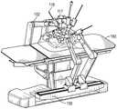
图1A示出了根据一个实施方案的外科机器人系统。Figure 1A shows a surgical robotic system according to one embodiment.
图1B示出了根据另选实施方案的外科机器人系统。Figure IB shows a surgical robotic system according to an alternative embodiment.
图2示出了根据一个实施方案的用于外科机器人系统的命令控制台。Figure 2 illustrates a command console for a surgical robotic system, according to one embodiment.
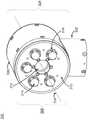
图3示出了根据一个实施方案的用于外科机器人系统的器械装置操纵器的透视图。Figure 3 shows a perspective view of an instrumentation manipulator for a surgical robotic system, according to one embodiment.
图4示出了根据一个实施方案的图3的器械装置操纵器的侧视图。4 illustrates a side view of the instrument device manipulator of FIG. 3, according to one embodiment.
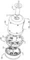
图5示出了根据一个实施方案的固定到图3的器械装置操纵器的示例性外科工具的前分解透视图。5 illustrates a front exploded perspective view of an exemplary surgical tool secured to the instrument device manipulator of FIG. 3 according to one embodiment.
图6示出了根据一个实施方案的固定到图3的器械装置操纵器的示例性外科工具的后分解透视图。6 illustrates a rear exploded perspective view of an exemplary surgical tool secured to the instrument device manipulator of FIG. 3 according to one embodiment.
图7示出了根据一个实施方案的用于外科工具与外科工具架的接合和脱离接合的致动机构的放大透视图。7 shows an enlarged perspective view of an actuation mechanism for engagement and disengagement of a surgical tool with a surgical tool holder, according to one embodiment.
图8A和图8B示出了根据一个实施方案的使外科工具与无菌适配器接合和脱离接合的过程。8A and 8B illustrate the process of engaging and disengaging a surgical tool with a sterile adapter, according to one embodiment.
图9A和图9B示出了根据另外的实施方案的使外科工具与无菌适配器接合和脱离接合的过程。9A and 9B illustrate the process of engaging and disengaging a surgical tool with a sterile adapter according to further embodiments.
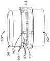
图10A示出了根据一个实施方案的用于使外科工具架在器械装置操纵器内滚动的机构的透视图。10A shows a perspective view of a mechanism for rolling a surgical tool holder within an instrument device manipulator, according to one embodiment.
图10B示出了根据一个实施方案的器械装置操纵器的剖视图。10B shows a cross-sectional view of an instrument device manipulator according to one embodiment.
图10C和10D示出了根据一个实施方案的器械装置操纵器的内部部件及其某些电子部件的局部分解透视图。10C and 10D show partially exploded perspective views of the internal components of an instrument device manipulator and some of its electronic components, according to one embodiment.
图10E示出了根据一个实施方案的器械装置操纵器的用于使外科工具架进行滚动分度的电子部件的放大透视图。10E shows an enlarged perspective view of the electronics of an instrument device manipulator for rolling indexing a surgical tool holder, according to one embodiment.
图11示出了根据一个实施方案的具有基于器械的插入架构的器械的侧视图。11 shows a side view of an instrument with an instrument-based insertion architecture, according to one embodiment.
图12示出了根据一个实施方案的用于致动端部执行器的第一致动机构的示意图。12 shows a schematic diagram of a first actuation mechanism for actuating an end effector, according to one embodiment.
图13示出了根据一个实施方案的图11的器械的第一致动机构的放大侧视图。Figure 13 shows an enlarged side view of the first actuation mechanism of the instrument of Figure 11, according to one embodiment.
图14示出了根据一个实施方案的图11的器械的第一致动机构的放大透视图。14 shows an enlarged perspective view of the first actuation mechanism of the instrument of FIG. 11 according to one embodiment.
图15示出了根据一个实施方案的图11的器械的滑轮和缆线在致动滑轮之前的视图。15 shows a view of the pulley and cable of the instrument of FIG. 11 prior to actuation of the pulley, according to one embodiment.
图16示出了根据一个实施方案的图11的器械的滑轮和缆线在致动滑轮之后的视图。16 shows a view of the pulley and cable of the instrument of FIG. 11 after actuation of the pulley, according to one embodiment.
图17示出了根据一个实施方案的包括用于轴平移的卷轴的第二致动机构的侧视图。17 shows a side view of a second actuation mechanism including a spool for shaft translation, according to one embodiment.
图18示出了根据一个实施方案的使用单根缆线进行轴平移的另选卷轴的透视图。18 shows a perspective view of an alternative spool using a single cable for axis translation, according to one embodiment.
图19示出了根据一个实施方案的使用多于一根缆线进行轴平移的另选卷轴的透视图。19 shows a perspective view of an alternative spool using more than one cable for axis translation, according to one embodiment.
图20示出了根据一个实施方案的包括图18的卷轴的柄部的前视图。20 illustrates a front view of a handle including the spool of FIG. 18, according to one embodiment.
图21示出了显示根据一个实施方案的用于致动端部执行器和轴平移的另选架构的示意图。Figure 21 shows a schematic diagram showing an alternative architecture for actuating the end effector and shaft translation, according to one embodiment.
图22A示出了根据一个实施方案的结合有图21的用于致动端部执行器和轴插入的另选架构的器械的放大前视图。22A illustrates an enlarged front view of an instrument incorporating the alternative architecture of FIG. 21 for actuating an end effector and shaft insertion, according to one embodiment.
图22B示出了根据一个实施方案的结合有图21的用于致动端部执行器和轴插入的另选架构的器械的顶部透视图。22B shows a top perspective view of an instrument incorporating the alternative architecture of FIG. 21 for actuating an end effector and shaft insertion, according to one embodiment.
图23示出了根据一个实施方案的器械的柄部和轴的顶部透视图。Figure 23 shows a top perspective view of the handle and shaft of an instrument according to one embodiment.
图24A示出了根据一个实施方案的利用图12所示的插入架构的器械轴的横截面的示意图。24A shows a schematic diagram of a cross-section of an instrument shaft utilizing the insertion architecture shown in FIG. 12, according to one embodiment.
图24B示出了根据一个实施方案的利用图21所示的插入架构的器械轴的横截面的示意图。24B shows a schematic diagram of a cross-section of an instrument shaft utilizing the insertion architecture shown in FIG. 21, according to one embodiment.
图25示出了显示根据一个实施方案的用于在血管闭合器中驱动刀的架构的示意图。Figure 25 shows a schematic diagram showing an architecture for driving a blade in a vessel closure according to one embodiment.
图26示出了显示根据一个实施方案的用于在血管闭合器中驱动刀的另选架构的示意图。Figure 26 shows a schematic diagram showing an alternative architecture for driving a blade in a vessel closure, according to one embodiment.
图27示出了显示根据一个实施方案的用于在血管闭合器中驱动刀的又一个另选架构的示意图。Figure 27 shows a schematic diagram showing yet another alternative architecture for driving a blade in a vessel closure according to one embodiment.
图28示出了显示根据一个实施方案的用于使得刚性相机成为插入器械的架构的示意图。28 shows a schematic diagram showing an architecture for making a rigid camera an insertion instrument, according to one embodiment.
图29示出了根据一个实施方案的允许相机与插入柄部分离的第一插入架构。Figure 29 illustrates a first insertion structure that allows the camera to be separated from the insertion handle, according to one embodiment.
图30和图31示出了根据一个实施方案的允许相机与插入柄部分离的第二插入架构。Figures 30 and 31 illustrate a second insertion architecture that allows separation of the camera from the insertion handle, according to one embodiment.
图32示出了显示根据另一个实施方案的用于轴平移的另选架构的图。32 shows a diagram showing an alternative architecture for axis translation according to another embodiment.
图33示出了具有多个密封件以防止来自患者的空气泄漏的器械的侧剖视图。33 shows a side cross-sectional view of an instrument with multiple seals to prevent air leakage from a patient.
图34示出了具有多个密封件的器械的前剖视图。Figure 34 shows a front cross-sectional view of an instrument with multiple seals.
附图仅出于说明目的描绘了本发明的实施方案。本领域的技术人员将从以下论述容易地认识到可在不脱离本文所述的本发明的原理的情况下采用本文所示的结构和方法的另选实施方案。The drawings depict embodiments of the present invention for purposes of illustration only. Those skilled in the art will readily appreciate from the following discussion that alternative embodiments of the structures and methods shown herein may be employed without departing from the principles of the invention described herein.
具体实施方式Detailed ways
I.外科机器人系统I. Surgical Robot System
图1A示出了外科机器人系统100的实施方案。外科机器人系统100包括基部101,该基部101耦接到一个或多个机器人臂,例如机器人臂102。基部101通信地耦接到本文参考图2进一步描述的命令控制台。基部101可被定位成使得机器人臂102能够进入以对患者执行外科手术,而用户诸如医师可根据命令控制台的舒适度来控制外科机器人系统100。在一些实施方案中,基部101可耦接到外科手术台或床以用于支撑患者。例如,在一些实施方案中,耦接到机器人臂102的基部101可经由沿床延伸的一个或多个导轨耦接到床(如图1B所示)。尽管为了清楚起见在图1A中未示出,但在一些实施方案中,基部101可包括子系统,诸如控制电子器件、气动装置、电源、光源等。机器人臂102包括在接头111处耦接的多个臂段110,这为机器人臂102提供多个自由度,例如,对应于七个臂段的七个自由度。基部101可包含电源112、气动压力装置113以及控制和传感器电子器件114—包括诸如中央处理单元、数据总线、控制电路和存储器的部件—以及诸如马达的相关致动器以使机器人臂102移动。基部101中的电子器件114还可处理和传输从命令控制台传达的控制信号。FIG. 1A shows an embodiment of a surgical
在一些实施方案中,基部101包括轮子115以运输外科机器人系统100。外科机器人系统100的移动性帮助适应外科手术室中的空间约束并且有利于外科设备的适当定位和移动。此外,移动性允许将机器人臂102配置为使得机器人臂102不妨碍患者、医师、麻醉师或任何其它设备。在程序期间,用户可使用控制装置诸如命令控制台来控制机器人臂102。In some embodiments,
在一些实施方案中,机器人臂102包括使用制动器和反向平衡装置的组合来保持机器人臂102的位置的装配接头。反向平衡装置可包括气弹簧或螺旋弹簧。制动器(例如故障保险制动器)可包括机械部件和/或电子部件。此外,机器人臂102可以是重力辅助被动支撑型机器人臂。In some embodiments, the
每个机器人臂102可使用机构变换接口(MCI)116耦接到器械装置操纵器(IDM)117。IDM 117可用作工具架。在一些实施方案中,可移除IDM 117并且替换成不同类型的IDM,例如,可将操纵内窥镜的第一类型的IDM替换成操纵腹腔镜的第二类型的IDM。MCI 116包括用于将气动压力、电功率、电信号和光信号从机器人臂102传送到IDM 117的连接器。MCI 116可以是定位螺钉或基板连接器。IDM 117使用包括直接驱动、谐波驱动、齿轮驱动、皮带和滑轮、磁驱动等的技术来操纵外科工具诸如器械118。MCI 116可基于IDM 117的类型互换,并且可针对某一类型的外科手术进行定制。机器人臂102可包括接头水平扭矩感测和在远侧端部处的腕部。Each
工具或器械118可包括能够在患者的外科部位处执行手术的腹腔镜式器械、内窥镜式器械和/或腔内器械。在一些实施方案中,器械118包括能够插入患者的切口中的腹腔镜式器械。腹腔镜式器械可包括刚性轴、半刚性轴或柔性轴。当设计用于腹腔镜手术时,轴的远侧端部可连接到端部执行器,该端部执行器可包括例如腕部、抓紧器、剪刀或其它外科工具。在一些实施方案中,器械118包括内窥镜式外科工具,该内窥镜式外科工具插入患者的解剖结构中以捕获解剖结构(例如,身体组织)的图像。在一些实施方案中,内窥镜式器械包括管状且柔性的轴。内窥镜包括捕获图像的一个或多个成像装置(例如,相机或传感器)。成像装置可包括一个或多个光学部件,诸如光纤、纤维阵列或透镜。光学部件与器械118的尖端一起移动,使得器械118的尖端的移动导致由成像装置捕获的图像的变化。在一些实施方案中,器械118包括能够穿过患者的自然孔口插入的腔内器械,诸如支气管镜或尿道镜。腔内器械可包括管状且柔性的轴。当设计用于腔内外科手术时,轴的远侧端部可连接到端部执行器,该端部执行器可包括例如腕部、抓紧器、剪刀或其它外科工具。The tools or
在一些实施方案中,外科机器人系统100的机器人臂102使用细长移动构件来操纵器械118。细长移动构件可包括拉线(也称为推拉线)、缆线、纤维或柔性轴。例如,机器人臂102致动耦接到器械118的多根拉线以使器械118的尖端偏转。拉线可包括金属材料和非金属材料两者,诸如不锈钢、Kevlar、钨、碳纤维等。在一些实施方案中,器械118可响应于由细长移动构件施加的力而表现出非线性行为。非线性行为可基于器械118的刚度和可压缩性,以及不同细长移动构件之间的松弛度或刚度的可变性。In some embodiments, the
外科机器人系统100包括控制器120,例如计算机处理器。控制器120包括校准模块125、图像配准模块130和校准存储装置135。校准模块125可使用具有分段线性响应的模型连同诸如斜率、滞后和盲区值的参数来表征非线性行为。外科机器人系统100可通过确定参数的准确值来更准确地控制内窥镜118。在一些实施方案中,控制器120的一些或所有功能在外科机器人系统100外部执行,例如,在通信地耦接到外科机器人系统100的另一个计算机系统或服务器上执行。The surgical
图1B示出了根据另选实施方案的外科机器人系统。类似于图1A中的外科机器人系统的实施方案,图1B中的外科机器人系统包括一个或多个机器人臂102,该一个或多个机器人臂102具有IDM 117和附接到其的外科工具或器械118。在本实施方案中,一个或多个机器人臂102附接到一个或多个可调节导轨150,该一个或多个可调节导轨150耦接到呈床形式的患者平台160。在本实施方案中,三个机器人臂102附接到患者平台160的第一侧上的可调节导轨150,而两个机器人臂102附接到患者平台160的第二侧上的可调节导轨150,从而提供具有双侧臂的系统。Figure IB shows a surgical robotic system according to an alternative embodiment. Similar to the embodiment of the surgical robotic system in FIG. 1A , the surgical robotic system in FIG. 1B includes one or more
II.命令控制台II. Command Console
图2示出了根据一个实施方案的用于外科机器人系统100的命令控制台200。命令控制台200包括控制台基部201、显示模块202例如监视器以及控制模块例如键盘203和操纵杆204。在一些实施方案中,命令模块200功能中的一者或多者可集成到外科机器人系统100的基部101或通信地耦接到外科机器人系统100的另一个系统中。用户205例如医师使用命令控制台200从人体工程学位置远程控制外科机器人系统100。FIG. 2 shows a
控制台基部201可包括中央处理单元、存储器单元、数据总线和相关联的数据通信端口,它们负责解释和处理信号诸如相机影像并且跟踪例如来自图1A所示的器械118的传感器数据。在一些实施方案中,控制台基部201和基部101两者都执行信号处理以实现负载平衡。控制台基部201还可处理由用户205通过控制模块203和204提供的命令和指令。除了图2所示的键盘203和操纵杆204之外,控制模块还可包括其它装置,例如计算机鼠标、跟踪垫、轨迹球、控制垫、视频游戏控制器以及捕获手姿势和手指姿势的传感器(例如,运动传感器或相机)。
用户205可使用命令控制台200在速度模式或位置控制模式中控制外科工具,诸如器械118。在速度模式中,用户205使用控制模块基于直接手动控制来直接控制器械118的远侧端部的俯仰和横摆运动。例如,可将操纵杆204上的移动映射到器械118的远侧端部中的横摆和俯仰移动。操纵杆204可向用户205提供触觉反馈。例如,操纵杆204振动以指示器械118无法在某一方向上进一步平移或旋转。命令控制台200还可提供视觉反馈(例如,弹出消息)和/或听觉反馈(例如,哔哔声)以指示器械118已达到最大平移或旋转。
在位置控制模式中,命令控制台200使用患者的三维(3D)地图和患者的预先确定的计算机模型来控制外科工具,例如器械118。命令控制台200向外科机器人系统100的机器人臂102提供控制信号以将器械118操纵到目标位置。由于依赖于3D地图,位置控制模式需要患者的解剖结构的准确制图。In the position control mode, the
在一些实施方案中,用户205可在不使用命令控制台200的情况下手动操纵外科机器人系统100的机器人臂102。在外科手术室中的装配期间,用户205可移动机器人臂102、器械118和其它外科设备以进入患者体内。外科机器人系统100可依赖来自用户205的力反馈和惯性控制来确定机器人臂102和设备的适当构型。In some embodiments, the
显示模块202可包括电子监视器、虚拟现实观看装置例如护目镜或眼镜和/或显示装置的其它装置。在一些实施方案中,显示模块202与控制模块集成,例如集成为具有触摸屏的平板装置。此外,用户205可使用集成的显示模块202和控制模块来观看数据并且将命令输入到外科机器人系统100。
显示模块202可使用立体装置例如遮阳板或护目镜来显示3D图像。3D图像提供“内视图”(即,内窥镜视图),它是示出患者的解剖结构的计算机3D模型。“内视图”提供患者内部的虚拟环境和器械118在患者体内的预期位置。用户205将“内视图”模型与由相机捕获的实际图像进行比较,以帮助在精神上定向并且确认器械118在患者体内处于正确—或大致正确—的位置。“内视图”提供关于器械118的远侧端部周围的解剖结构的信息,例如患者的小肠或结肠的形状。显示模块202可同时显示器械118的远侧端部周围的解剖结构的3D模型和计算机断层摄影(CT)扫描。此外,显示模块202可将器械118的预先确定的最佳导航路径叠加在3D模型和CT扫描上。The
在一些实施方案中,器械118的模型与3D模型一起显示以帮助指示外科手术的状态。例如,CT扫描识别可能需要进行活检的解剖结构中的病变。在操作期间,显示模块202可示出对应于器械118的当前位置的由器械118捕获的参考图像。显示模块202可根据用户设置和特定外科手术来自动显示器械118的模型的不同视图。例如,显示模块202示出在导航步骤期间在器械118接近患者的操作区域时的器械118的顶部荧光镜视图。In some embodiments, a model of the
III.器械装置操纵器III. Instrument Manipulator
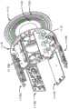
图3示出了根据一个实施方案的用于外科机器人系统的器械装置操纵器(IDM)300的透视图,并且图4是根据一个实施方案的IDM 300的侧视图。IDM 300被配置为以允许外科工具围绕外科工具的轴线连续旋转或“滚动”的方式将外科工具或器械附接到机器人外科臂。IDM 300包括基部302和耦接到基部的外科工具架组件304。外科工具架组件304用作用于固持器械118的工具架。外科工具架组件304还包括外部壳体306、外科工具架308、附接接口310、通道312和多个扭矩耦接器314。在一些实施方案中,通道312包括从IDM 300的一个面延伸到IDM 300的相背面的通孔。IDM 300可与多种外科工具(图3未示出)一起使用,该多种外科工具可包括柄部和细长主体(例如,轴)并且可用于腹腔镜、内窥镜或其它类型的外科工具的端部执行器。3 shows a perspective view of an instrument device manipulator (IDM) 300 for a surgical robotic system, according to one embodiment, and FIG. 4 is a side view of the
基部302将IDM 300可移除地或固定地安装到外科机器人系统的外科机器人臂。在图3的实施方案中,基部302固定地附接到外科工具架组件304的外部壳体306。在另选的实施方案中,基部302可被构造为包括平台,该平台适于将外科工具架308可旋转地接收在与附接接口310相背的面上。平台可包括与通道312对准的通道以接收外科工具的细长主体,以及在一些实施方案中,与第一外科工具同轴安装的第二外科工具的另外的细长主体。
外科工具架组件304被配置为将外科工具固定到IDM 300并且使外科工具相对于基部302旋转。提供从外科臂到基部302然后到外科工具架组件304的机械连接和电气连接,以使外科工具架308相对于外部壳体306旋转并且将功率和/或信号从外科臂操纵和/或递送到外科工具架308并且最终到外科工具。信号可包括气动压力的信号、电功率的信号、电信号和/或光信号。The surgical
外部壳体306相对于基部302为外科工具架组件304提供支撑。外部壳体306固定地附接到基部302,使得其相对于基部302保持固定,同时允许外科工具架308相对于外部壳体306自由旋转。在图3的实施方案中,外部壳体306在形状上是圆柱形的并且完全外接外科工具架308。外部壳体306可由刚性材料(例如,金属或硬塑料)构成。在另选的实施方案中,壳体的形状可变化。
外科工具架308经由附接接口310将外科工具固定到IDM 300。外科工具架308能够独立于外部壳体306旋转。外科工具架308围绕旋转轴线316旋转,该旋转轴线316与外科工具的细长主体同轴对准,使得外科工具与外科工具架308一起旋转。
附接接口310是外科工具架308的附接到外科工具的面。附接接口310包括附接机构的第一部分,该第一部分与附接机构的位于外科工具上的第二部分往复地配合,这将相对于图8A和图8B更详细地讨论。在一些实施方案中,附接接口310包括多个扭矩耦接器314,该多个扭矩耦接器314从附接接口310向外突出并且与外科工具上的相应器械输入端接合。在一些实施方案中,耦接到无菌适配器的外科盖布可用于在IDM 300和外科工具之间形成无菌边界。在这些实施方案中,当外科工具固定到IDM 300时,无菌适配器可定位在附接接口310和外科工具之间,使得外科盖布将外科工具和患者与IDM 300和外科机器人系统分离。The
通道312被配置为当外科工具固定到附接接口310时接收外科工具的细长主体。在图3的实施方案中,通道312与外科工具的细长主体的纵向轴线和外科工具架308的旋转轴线316同轴对准。通道312允许外科工具的细长主体在通道312内自由旋转。这种构型允许外科工具围绕旋转轴线316在任一方向上在极小约束下或无约束地连续旋转或滚动。
多个扭矩耦接器314被配置为当外科工具固定到外科工具架308时接合并且驱动外科工具的部件。每个扭矩耦接器314插入位于外科工具上的相应器械输入端中。多个扭矩耦接器314还可用于保持外科工具和外科工具架308之间的旋转对准。如图3所示,每个扭矩耦接器314被成形为从附接接口310向外突出的圆柱形突出部。凹口318可沿圆柱形突出部的外表面区域布置。在一些实施方案中,凹口318的布置形成花键接口。外科工具上的器械输入端被配置为具有与扭矩耦接器314互补的几何形状。例如,虽然图3未示出,但是外科工具的器械输入端在形状上可以是圆柱形的并且具有多个脊,该多个脊与每个扭矩耦接器314上的多个凹口318往复地配合并且因此在凹口318上施加扭矩。在另选的实施方案中,圆柱形突出部的顶面可包括多个凹口318,该多个凹口被配置为与相应器械输入端中的多个脊配合。在这种构型中,每个扭矩耦接器314与其相应器械输入端完全接合。The plurality of
另外,每个扭矩耦接器314可耦接到允许扭矩耦接器平移的弹簧。在图3的实施方案中,弹簧引起每个扭矩耦接器314被偏置以背离附接接口310向外弹开。弹簧被配置为在轴向方向上产生平移,即,背离附接接口310伸出并且朝向外科工具架308回缩。在一些实施方案中,每个扭矩耦接器314能够部分地回缩到外科工具架308中。在其它实施方案中,每个扭矩耦接器314能够完全回缩到外科工具架308中,使得每个扭矩耦接器的有效高度相对于附接接口310为零。在图3的实施方案中,每个扭矩耦接器314的平移由致动机构致动,这将相对于图7-图8更详细地描述。在各种实施方案中,每个扭矩耦接器314可耦接到单个弹簧、多个弹簧或每个扭矩耦接器的相应弹簧。Additionally, each
此外,每个扭矩耦接器314由相应致动器驱动,该相应致动器引起扭矩耦接器在任一方向上旋转。因此,一旦与器械输入端接合,每个扭矩耦接器314就能够传输功率以收紧或松开外科工具内的拉线,从而操纵外科工具的端部执行器。在图3的实施方案中,IDM 300包括五个扭矩耦接器314,但在其它实施方案中,数量可根据外科工具的端部执行器的期望数量的自由度变化。在一些实施方案中,耦接到无菌适配器的外科盖布可用于在IDM 300和外科工具之间形成无菌边界。在这些实施方案中,当外科工具固定到IDM 300时,无菌适配器可定位在附接接口310和外科工具之间,并且无菌适配器可被配置为将功率从每个扭矩耦接器314传输到相应器械输入端。Additionally, each
图3所示的IDM 300的实施方案可以各种构型与外科机器人系统一起使用。期望构型可取决于正对患者执行的外科手术的类型或在外科手术期间使用的外科工具的类型。例如,对于内窥镜式手术与腹腔镜式手术,IDM 300的期望构型可不同。The embodiment of
在第一构型中,IDM 300能够可移除地或固定地附接到外科臂,使得附接接口310在外科手术期间在患者近侧。在这种构型(下文称为“前安装式构型”)中,外科工具在位于患者近侧的一侧上固定到IDM 300。与前安装式构型一起使用的外科工具被构造成使得外科工具的细长主体从与外科工具的附接接口相背的一侧延伸。当将外科工具从呈前安装式构型的IDM 300移除时,将在患者的近侧方向上移除外科工具。In the first configuration, the
在第二构型中,IDM 300能够可移除地或固定地附接到外科臂,使得附接接口310在外科手术期间在患者远侧。在这种构型(下文称为“后安装式构型”)中,外科工具在远离患者的一侧上固定到IDM 300。与后安装式构型一起使用的外科工具被构造成使得外科工具的细长主体从外科工具的附接接口延伸。这种构型增加了患者在从IDM 300移除工具期间的安全性。当将外科工具从呈后安装式构型的IDM 300移除时,将在患者的远侧方向上移除外科工具。In the second configuration, the
在第三构型中,IDM 300能够可移除地或固定地附接到外科臂,使得外科工具的至少一部分定位在IDM 300上方,类似于图1A所示的构型。在这种构型(下文称为“顶部”或“贯通”构型)中,外科工具的轴向下延伸穿过IDM 300。In a third configuration, the
外科工具的某些构型可被构造成使得外科工具可以前安装式构型或后安装式构型与IDM一起使用。在这些构型中,外科工具在外科工具的两个端部上包括附接接口。对于一些外科手术,医师可根据正在执行的外科手术的类型决定IDM的构型。例如,后安装式构型对于其中腹腔镜式工具相对于其它外科工具可能特别长的腹腔镜式手术可以是有益的。当外科臂在外科手术期间四处移动时,诸如当医师将外科工具的远侧端部引导到患者的远程位置(例如,肺或血管)时,腹腔镜式工具的增加的长度引起外科臂围绕更大的弧摆动。有益地,后安装式构型通过穿过通道312接收细长主体的一部分来减小外科工具的有效工具长度,从而减小外科臂对外科工具进行定位所需的运动弧。Certain configurations of the surgical tool can be configured such that the surgical tool can be used with the IDM in either a front-mounted configuration or a rear-mounted configuration. In these configurations, the surgical tool includes attachment interfaces on both ends of the surgical tool. For some surgical procedures, the physician may determine the configuration of the IDM based on the type of surgical procedure being performed. For example, the rear-mounted configuration may be beneficial for laparoscopic procedures in which laparoscopic tools may be particularly long relative to other surgical tools. The increased length of the laparoscopic tool causes the surgical arm to wrap around more Big arc swing. Beneficially, the rear mounted configuration reduces the effective tool length of the surgical tool by receiving a portion of the elongated body through the
图5-图6示出了根据一个实施方案的固定到图3的器械装置操纵器300的示例性外科工具500的分解透视图。外科工具500包括壳体502、细长主体504和多个器械输入端600。如前所述,细长主体504可以是腹腔镜、内窥镜或具有端部执行器的其它外科工具。如图所示,多个扭矩耦接器314从附接接口310向外突出以与外科工具的器械输入端600接合。器械输入端600的结构可见于图6中,其中器械输入端600具有与扭矩耦接器314对应的几何形状以确保固定的外科工具接合。5-6 illustrate exploded perspective views of an exemplary
在外科手术期间,外科盖布可用于保持IDM 300和外部环境(即,手术室)之间的无菌边界。在图5-图6的实施方案中,外科盖布包括无菌适配器506、第一突出部508和第二突出部510。虽然在图5-图6中未示出,但是无菌片材连接到无菌适配器和第二突出部并披盖在IDM 300周围以形成无菌边界。During surgical procedures, surgical drapes can be used to maintain a sterile boundary between the
无菌适配器506被配置为当固定到IDM 300时在IDM 300和外科工具500之间形成无菌接口。在图5-图6的实施方案中,无菌适配器506具有覆盖IDM 300的附接接口310的盘状几何形状。无菌适配器506包括中心孔508,该中心孔508被配置为接收外科工具500的细长主体504。在这种构型中,当外科工具500固定到IDM 300时,无菌适配器506定位在附接接口310和外科工具500之间,从而在外科工具500和IDM 300之间形成无菌边界并且允许细长主体504穿过通道312。在某些实施方案中,无菌适配器506可能够与外科工具架308一起旋转,将旋转扭矩从多个扭矩耦接器314传输到外科工具500,在IDM 300和外科工具500之间传递电信号,或它们的某种组合。
在图5-图6的实施方案中,无菌适配器506还包括多个耦接器512。耦接器512的第一侧被配置为与相应扭矩耦接器314接合,而耦接器512的第二侧被配置为与相应器械输入端600接合。In the embodiment of FIGS. 5-6 , the
类似于多个扭矩耦接器314的结构,每个耦接器512被构造为包括多个凹口的圆柱形突出部。耦接器512的每一侧具有互补的几何形状以与相应扭矩耦接器314和相应器械输入端600完全接合。在一些实施方案中,一个或多个器械输入端600称为机械输入端。每个耦接器512被配置为在顺时针或逆时针方向上与相应扭矩耦接器314一起旋转。这种构型允许每个耦接器512将旋转扭矩从IDM 300的多个扭矩耦接器314传送到外科工具500的多个器械输入端600,并且因此控制外科工具500的端部执行器。Similar to the structure of the plurality of
第一突出部508和第二突出部510被配置为穿过IDM 300的通道312并且在通道312内彼此配合。每个突出部508、510被构造为允许细长主体504穿过突出部并且因此穿过通道312。第一突出部508和第二突出部510的连接在IDM 300和外部环境(即,手术室)之间形成无菌边界。The
IV.外科工具脱离接合IV. Surgical Tool Disengagement
图7示出了根据一个实施方案的用于外科工具500与外科盖布的无菌适配器506的接合和脱离接合的致动机构的放大透视图。由于如相对于图3所述的IDM 300的构型,外科手术期间到患者体内的外科工具插入的轴线与外科工具移除的轴线相同。为了确保患者在外科工具移除期间的安全性,可在移除外科工具500之前使外科工具500与无菌适配器506和IDM 300脱离铰接。在图7的实施方案中,多个耦接器512被配置为在轴向方向上平移,即,背离无菌适配器506伸出并且朝向无菌适配器506回缩。多个耦接器512的平移由致动机构致动,该致动机构通过使多个耦接器512与相应器械输入端600脱离接合来确保外科工具500的脱离铰接。致动机构包括楔形件702和推动板704。7 shows an enlarged perspective view of an actuation mechanism for engagement and disengagement of a
楔形件702是在外科工具脱离接合的过程期间启动推动板704的结构部件。在图7的实施方案中,楔形件702沿外科工具500的壳体502的外周边位于壳体502内。如图所示,楔形件702被定向成使得如果外科工具500的壳体502相对于无菌适配器506顺时针旋转,则与推动板704的接触引起推动板704下压到无菌适配器506中。在另选的实施方案中,楔形件702可被配置为使得外科工具500的壳体502逆时针而不是顺时针旋转。可采用除楔形之外的几何形状,诸如拱形斜坡,只要该结构能够在旋转时压下推动板即可。The
推动板704是使多个耦接器512与外科工具500脱离接合的致动器。类似于多个扭矩耦接器314,耦接器512中的每一个耦接器可耦接到一个或多个弹簧,该一个或多个弹簧使每个耦接器512偏置以背离无菌适配器506向外弹开。多个耦接器512进一步被配置为在轴向方向上平移,即,背离无菌适配器506伸出并且回缩到无菌适配器506中。推动板704致动耦接器512的平移移动。当推动板704被楔形件702压下时,推动板704引起耦接到每个耦接器512的一个或多个弹簧压缩,从而导致耦接器512回缩到无菌适配器506中。在图7的实施方案中,推动板704被配置为引起多个耦接器512同时回缩。另选的实施方案可使耦接器512按特定序列或随机顺序回缩。在图7的实施方案中,推动板704引起多个耦接器512部分地回缩到无菌适配器506中。这种构型允许在移除外科工具500之前使外科工具500与无菌适配器506脱离铰接。这种构型还允许用户在任何期望的时间使外科工具500与无菌适配器506脱离铰接而无需移除外科工具500。另选的实施方案可使多个耦接器512完全回缩到无菌适配器506中,使得所测量的每个耦接器512的有效高度为零。在一些实施方案中,推动板704可引起多个扭矩耦接器314与多个相应耦接器512同步回缩。
图8A和图8B示出了根据一个实施方案的使外科工具与无菌适配器接合和脱离接合的过程。图8A示出了在固定位置中的无菌适配器506和外科工具500,使得两个部件固定在一起并且多个耦接器512与外科工具500的相应的器械输入端600完全接合。为了实现如图8A所示的固定位置,使外科工具500的细长主体504(未示出)穿过无菌适配器506的中心孔508(未示出),直到外科工具500和无菌适配器506的配合表面接触为止,并且通过闭锁机构将外科工具500和无菌适配器506彼此固定。在图8A和图8B的实施方案中,闭锁机构包括横档802和闩锁804。8A and 8B illustrate the process of engaging and disengaging a surgical tool with a sterile adapter, according to one embodiment. FIG. 8A shows the
横档802是在固定位置中固定闩锁804的结构部件。在图8A的实施方案中,横档802沿外科工具500的壳体502的外周边位于壳体502内。如图8A所示,横档802被定向成使得其搁置在闩锁804上的突出部下方,从而防止闩锁804并由此防止无菌适配器506由于多个耦接器512的上弹性质而远离外科工具500拉动,如相对于图7所述。The
闩锁804是在固定位置中与横档802配合的结构部件。在图8A的实施方案中,闩锁804从无菌适配器506的配合表面突出。闩锁804包括突出部,该突出部被配置为当外科工具500固定到无菌适配器506时抵靠横档802。在图8A的实施方案中,外科工具500的壳体502能够独立于外科工具500的其余部分旋转。这种构型允许壳体502相对于无菌适配器506旋转,使得横档802抵靠闩锁804固定,从而将外科工具500固定到无菌适配器502。在图8A的实施方案中,壳体502逆时针旋转以实现固定位置,但其它实施方案可被配置用于顺时针旋转。在另选的实施方案中,横档802和闩锁804可具有将无菌适配器506和外科工具500锁定在固定位置中的各种几何形状。The
图8B示出了在解除固定位置中的无菌适配器506和外科工具500,在解除固定位置中,外科工具500可从无菌适配器506移除。如前所述,外科工具500的壳体502能够独立于外科工具500的其余部分旋转。这种构型允许壳体502旋转,即使在多个耦接器512与外科工具500的器械输入端600接合时也是如此。为了从固定位置转变到解除固定位置,用户使外科工具500的壳体502相对于无菌适配器506顺时针旋转。在此旋转期间,楔形件702接触推动板704并且随着推动板704抵靠楔形件702的成角度平面滑动而逐渐压下推动板704,从而引起多个耦接器512回缩到无菌适配器506中并且与多个器械输入端600脱离接合。进一步旋转引起闩锁804接触轴向凸轮806,该轴向凸轮806的构造类似于楔形件702。当闩锁804在旋转期间接触轴向凸轮806时,轴向凸轮806引起闩锁804背离外科工具500向外挠曲,使得闩锁804从横档802移位。在图8B的实施方案中,在这个解除固定位置中,多个耦接器512回缩,并且外科工具500可从无菌适配器506移除。在其它实施方案中,轴向凸轮806可具有各种几何形状,使得旋转引起闩锁804向外挠曲。FIG. 8B shows the
在另选的实施方案中,外科工具500的壳体502的旋转方向可被配置为逆时针旋转以使闩锁804与横档802解除固定。另外,另选的实施方案可包括类似的部件,但是部件的位置可在无菌适配器506和外科工具500之间切换。例如,横档802可位于无菌适配器506上,而闩锁804可位于外科工具500上。在其它实施方案中,无菌适配器506的外部部分可能够相对于多个耦接器512而不是外科工具500的壳体502旋转。另选的实施方案还可包括用于在壳体502相对于器械输入端600完全旋转时锁定外科工具502的壳体502的旋转的特征件。如果器械输入端600已经与耦接器512脱离铰接,则这种构型防止外科工具的旋转。在一些实施方案中,耦接器512的回缩和伸出可与扭矩耦接器314的相应回缩和伸出耦接,使得与扭矩耦接器314接合的耦接器512将一起平移。In alternative embodiments, the rotational direction of the
图9A和图9B示出了根据另一个实施方案的外科工具与无菌适配器的外科工具接合和脱离接合的过程。在图9A和图9B的实施方案中,无菌适配器900可包括将外科工具904固定到无菌适配器900的外带902。如图9A和9B所示,外科工具902在壳体908的外表面上包括斜坡906。斜坡906包括凹口910,该凹口910被配置为接收圆形突出部912,该圆形突出部912定位在无菌适配器900的外带902的内表面上。外带902能够独立于并且相对于无菌适配器900和外科工具904旋转。当外带902在第一方向上旋转时,圆形突出部912沿着斜坡906的表面向上滑动,直到圆形突出部912嵌套在凹口910内,从而将无菌适配器900和外科工具904固定在一起。外带902在第二方向上的旋转引起无菌适配器900和外科工具904与彼此解除固定。在某些实施方案中,这种机构可与无菌适配器900上的多个耦接器914的脱离铰接相结合,如相对于图7-图8所述。9A and 9B illustrate the process of engaging and disengaging a surgical tool with a surgical tool of a sterile adapter according to another embodiment. In the embodiment of FIGS. 9A and 9B , the
外科工具脱离接合的另选的实施方案可包括另外的特征,诸如阻抗模式。利用阻抗模式,外科机器人系统可控制用户是否可将外科工具从无菌适配器移除。用户可通过旋转外科工具的壳体并且将外科工具与无菌适配器解除固定来开启脱离接合机构,但外科机器人系统可不会从器械输入端释放耦接器。只有当外科机器人系统已经转变到阻抗模式时,耦接器才被释放并且用户才可移除外科工具。保持外科工具接合的优点在于:外科机器人系统可在移除外科工具之前控制外科工具的端部执行器并且对端部执行器进行定位以用于工具移除,以使对外科工具的损坏最小化。为了启动阻抗模式,推动板704可具有硬止动件,使得推动板可被压下至多一定距离。在一些实施方案中,推动板的硬止动件可以是可调节的,使得硬止动件与外科工具的壳体的最大旋转量重合。因此,一旦达到完全旋转,推动板也就遇到硬止动件。多个传感器可检测这些事件并且触发阻抗模式。Alternative embodiments of surgical tool disengagement may include additional features, such as impedance patterns. Using the impedance mode, the surgical robotic system can control whether the user can remove the surgical tool from the sterile adapter. The user may open the disengagement mechanism by rotating the housing of the surgical tool and de-securing the surgical tool from the sterile adapter, but the surgical robotic system may not release the coupling from the instrument input. Only when the surgical robotic system has transitioned to impedance mode is the coupler released and the user can remove the surgical tool. The advantage of keeping the surgical tool engaged is that the surgical robotic system can control the end effector of the surgical tool and position the end effector for tool removal prior to removal of the surgical tool to minimize damage to the surgical tool . To activate the impedance mode, the
在可能不期望阻抗模式的外科手术期间,某些情况可能需要进行紧急工具移除。在一些实施方案中,推动板的硬止动件可具有顺应性,使得硬止动件在紧急情况下可屈曲。推动板的硬止挡件可耦接到弹簧,从而允许硬止动件响应于另外的力而屈曲。在其它实施方案中,推动板的硬止动件可以是刚性的,使得通过移除将外科工具固定到无菌适配器的闩锁来进行紧急工具移除。Certain situations may require emergency tool removal during surgical procedures where impedance patterns may not be desired. In some embodiments, the hard stop of the push plate can be compliant so that the hard stop can flex in an emergency. The hard stop of the push plate may be coupled to a spring, allowing the hard stop to flex in response to additional force. In other embodiments, the hard stop of the push plate may be rigid such that emergency tool removal is performed by removing the latch securing the surgical tool to the sterile adapter.
V.滚动机构V. Rolling Mechanism
图10A示出了根据一个实施方案的用于使外科工具架308在器械装置操纵器300内滚动的机构的透视图。如图10A所示,附接接口310被移除以暴露滚动机构。这种机构允许外科工具架308围绕旋转轴线316在任一方向上连续旋转或“滚动”。滚动机构包括定子齿轮1002和转子齿轮1004。10A shows a perspective view of a mechanism for rolling a
定子齿轮1002是被配置为与转子齿轮1004配合的固定齿轮。在图10A的实施方案中,定子齿轮1002是沿环的内圆周包括齿轮齿的环形齿轮。定子齿轮1002在附接接口310后面固定地附接到外部壳体306。定子齿轮1002具有与转子齿轮1004相同的齿距,使得定子齿轮1002的齿轮齿被配置为与转子齿轮1004的齿轮齿配合。定子齿轮1002可由刚性材料(例如,金属或硬塑料)构成。
转子齿轮1004是被配置为引起外科工具架308旋转的旋转齿轮。如图10A所示,转子齿轮1004是沿其外圆周包括齿轮齿的圆形齿轮。转子齿轮1004定位在附接接口310后面且在定子齿轮1002的内圆周内,使得转子齿轮1004的齿轮齿与定子齿轮的齿轮齿配合。如前所述,转子齿轮1004和定子齿轮1002具有相同的齿距。在图10A的实施方案中,转子齿轮1004耦接到驱动机构(例如,马达),该驱动机构引起转子齿轮1004在顺时针或逆时针方向上旋转。驱动机构可从外科工具架组件304内的集成控制器接收信号。当驱动机构引起转子齿轮1004旋转时,转子齿轮1004沿定子齿轮1002的齿轮齿行进,从而引起外科工具架308旋转。在这种构型中,转子齿轮1004能够在任一方向上连续旋转,并且因此允许外科工具架308围绕旋转轴线316实现无限滚动。另选的实施方案可使用类似的机构来允许无限滚动,诸如环形齿轮和小齿轮的构型。
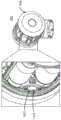
图10B示出了根据一个实施方案的器械装置操纵器300的剖视图。如图10B所示,滚动机构与多个轴承1006耦接。轴承是减小移动部分之间的摩擦并且有利于围绕固定轴线旋转的机械部件。当外科工具架308在外部壳体306内旋转时,一个轴承可单独地支撑径向或扭转载荷。在图10B的实施方案中,IDM 300包括两个轴承1006a、1006b,它们固定地附接到外科工具架308,使得轴承1006内的多个部件(诸如滚珠或滚筒)接触外部壳体306。第一轴承1006a在第一端部处固定在附接接口310后面,并且第二轴承1006b固定在第二端部处。这种构型改善了在外科工具架308在外部壳体306内旋转时外科工具架308的第一端部和第二端部之间的刚性和支撑。另选的实施方案可包括另外的轴承,这些另外的轴承沿外科工具架的长度提供另外的支撑。FIG. 10B shows a cross-sectional view of the
图10B还示出了根据一个实施方案的IDM 300内的密封部件。IDM 300包括多个O形环1008和多个垫圈1010,该多个O形环1008和该多个垫圈1010被配置为密封两个表面之间的结合部,以防止流体进入该结合部。在图10B的实施方案中,IDM包括位于外部壳体的结合部之间的O形环1008a、1008b、1008c、1008d、1008e以及位于外科工具架308内的结合部之间的垫圈1010a、1010b。这种构型帮助保持IDM 300内的部件在外科手术期间的无菌性。垫圈和O形环通常由强弹性体材料(例如,橡胶)构成。FIG. 10B also shows sealing components within the
VI.电子部件VI. Electronic Components
图10C示出了根据一个实施方案的器械装置操纵器的内部部件及其某些电子部件的局部分解透视图。外科工具架308的内部部件包括多个致动器1102、马达、齿轮头(未示出)、扭矩传感器(未示出)、扭矩传感器放大器1110、滑环1112、多个编码器板1114、多个马达功率板1116和集成控制器1118。Figure 1OC shows a partially exploded perspective view of the internal components of an instrument device manipulator and some of its electronic components, according to one embodiment. The internal components of the
多个致动器1102驱动多个扭矩耦接器314中的每一个扭矩耦接器的旋转。在图10C的实施方案中,致动器诸如1102a或1102b经由马达轴耦接到扭矩耦接器314。马达轴可以是键合轴,使得其包括多个沟槽以允许马达轴固定地配合到扭矩耦接器314。致动器1102引起马达轴在顺时针或逆时针方向上旋转,从而引起相应扭矩耦接器314在该方向上旋转。在一些实施方案中,马达轴可以是扭转刚性的但弹簧顺应性的,从而允许马达轴并且因此允许扭矩耦接器314旋转并在轴向方向上平移。这种构型可允许多个扭矩耦接器314在外科工具架308内回缩和伸出。每个致动器1102可从集成控制器1118接收指示使马达轴旋转的方向和量的电信号。在图10C的实施方案中,外科工具架308包括五个扭矩耦接器314并且因此包括五个致动器1102。The plurality of actuators 1102 drive rotation of each of the plurality of
马达驱动外科工具架308在外部壳体306内的旋转。马达可在结构上等同于致动器中的一个致动器,不同的是马达耦接到转子齿轮1004和定子齿轮1002(参见图10A)以用于使外科工具架308相对于外部壳体306旋转。马达引起转子齿轮1004在顺时针或逆时针方向上旋转,从而引起转子齿轮1004围绕定子齿轮1002的齿轮齿行进。这种构型允许外科工具架308连续滚动或旋转,而不受缆线或拉线的潜在绕起的阻碍。马达可从集成控制器1118接收指示使马达轴旋转的方向和量的电信号。The motor drives the rotation of the
齿轮头控制递送到外科工具500的扭矩量。例如,齿轮头可增加递送到外科工具500的器械输入端600的扭矩量。另选的实施方案可被配置为使得齿轮头减小递送到器械输入端600的扭矩量。The gear head controls the amount of torque delivered to the
扭矩传感器测量在旋转的外科工具架308上产生的扭矩量。在图10C所示的实施方案中,扭矩传感器能够测量顺时针和逆时针方向上的扭矩。扭矩测量结果可用于保持外科工具的多根拉线中的特定张力量。例如,外科机器人系统的一些实施方案可具有自动张紧特征,其中在给外科机器人系统通电或使外科工具与IDM接合时,外科工具的拉线上将被预加载张力。每根拉线上的张力量可达到阈值量,使得拉线被张紧到刚好足以绷紧。扭矩传感器放大器1110包括用于放大测量在旋转的外科工具架308上产生的扭矩量的信号的电路。在一些实施方案中,扭矩传感器安装到马达。The torque sensor measures the amount of torque developed on the rotating
滑环1112使得能够将电功率和信号从固定结构传送到旋转结构。在图10C的实施方案中,滑环1112被构造为包括中心孔的环,该中心孔被配置为与外科工具架308的通道312对准,如也在图10D中的滑环1112的另外的透视图中所示。滑环1112的第一侧包括多个同心沟槽1120,而滑环1112的第二侧包括多个电气部件,该多个电气部件用于从外科臂和基部302提供的电气连接,如相对于图3所述。滑环1112在距外部壳体306的特定距离处固定到外科工具架308的外部壳体306,以为这些电气连接分配空间。多个同心沟槽1120被配置为与附接到集成控制器的多个电刷1122配合。沟槽1120和电刷1122之间的接触使得能够将电功率和信号从外科臂和基部传送到外科工具架。The
多个编码器板1114读取并处理通过滑环从外科机器人系统接收的信号。从外科机器人系统接收的信号可包括指示外科工具的旋转量和旋转方向的信号、指示外科工具的端部执行器和/或腕部的旋转量和旋转方向的信号、操作外科工具上的光源的信号、操作外科工具上的视频或成像装置的信号、以及操作外科工具的各种功能的其它信号。编码器板1114的配置允许在外科工具架308中完全执行整个信号处理。多个马达功率板1116各自包括用于向马达提供功率的电路。A number of encoder boards 1114 read and process signals received from the surgical robotic system through the slip rings. Signals received from the surgical robotic system may include signals indicative of the amount and direction of rotation of the surgical tool, signals indicative of the amount and direction of rotation of the surgical tool's end effector and/or wrist, signals that operate a light source on the surgical tool Signals, signals that operate video or imaging devices on the surgical tool, and other signals that operate various functions of the surgical tool. The configuration of the encoder board 1114 allows the entire signal processing to be fully performed in the
集成控制器1118是外科工具架308内的计算装置。在图10C的实施方案中,集成控制器1118被构造为包括中心孔的环,该中心孔被配置为与外科工具架308的通道312对准。集成控制器1118在集成控制器1118的第一侧上包括多个电刷1122。电刷1122接触滑环1112并且接收从外科机器人系统通过外科臂、基部302并且最终通过滑环1112递送到集成控制器1118的信号。由于所接收的信号,集成控制器1118被配置为将各种信号发送到外科工具架308内的相应部件。在一些实施方案中,编码器板1114和集成控制器1118的功能可以与本文所述不同的方式分布,使得编码器板1114和集成控制器1118可执行相同的功能或它们的某种组合。The
图10D示出了根据一个实施方案的器械装置操纵器的内部部件及其某些电子部件的局部分解透视图。图10D的实施方案包括两个编码器板1114a和1114b、扭矩传感器放大器1110以及三个马达功率板1116a、1116b和1116c。这些部件固定到集成控制器1118并且向外突出,从而从集成控制器1118垂直延伸。这种构型为将多个致动器1102和马达定位在电路板内提供空间。10D shows a partially exploded perspective view of the internal components of an instrument device manipulator and some of its electronic components, according to one embodiment. The embodiment of Figure 10D includes two
如相对于图10C所讨论的,滑环1112固定在距外部壳体306的特定距离处。为了确保滑环1112和外部壳体306之间用于从外科臂和基部302到滑环1112的电气连接的正确空间分配,在图10D的实施方案中,滑环1112由多个对准销、多个螺旋弹簧和一个垫片支撑。滑环1112在滑环1112的中心孔的每一侧上包括孔1124,该孔1124被配置为在对准销的第二侧插入外部壳体306中的相应孔中时接受对准销的第一侧。对准销可由刚性材料(例如,金属或硬塑料)构成。多个螺旋弹簧围绕滑环1112的中心固定并且被配置为桥接滑环1112和外部壳体306之间的空间并且保持它们之间的接触。螺旋弹簧可有益地吸收对IDM 300的任何冲击。垫片是环形间隔件,其围绕滑环1112的中心孔定位以在滑环1112和外部壳体306之间添加进一步的支撑。此外,当集成控制器1118上的多个电刷1122接触多个同心沟槽1120并且抵靠该多个同心沟槽1120旋转时,这些部件向滑环1112提供稳定性。在另选的实施方案中,对准销、螺旋弹簧和垫片的数量可发生变化,直到实现滑环1112和外部壳体306之间的期望支撑。As discussed with respect to FIG. 10C , the
图10E示出了根据一个实施方案的器械装置操纵器300的用于使外科工具架308进行滚动分度的电子部件的放大透视图。滚动分度监视外科工具架308相对于外部壳体306的位置,使得外科机器人系统不断了解外科工具500的位置和取向。图10E的实施方案包括微动开关1202和凸出部1204。微动开关1202和凸出部1204固定在外科工具架308内。凸出部1204是外部壳体306上的结构,该结构被配置为在外科工具架308旋转时接触微动开关1202,由此每当与凸出部1204接触时就启动微动开关。在图10E的实施方案中,存在一个凸出部1204,其用作用于微动开关1202的单个基准点。FIG. 10E shows an enlarged perspective view of the electronics of the
VII.具有基于器械的插入架构的器械VII. Devices with Device-Based Insertion Architectures
各种工具或器械可附接到IDM 300,包括用于腹腔镜式外科手术、内窥镜式外科手术和腔内外科手术的器械。本文所述的器械是特别新颖的,因为它们包括基于器械的插入架构,这降低了插入对机器人臂的依赖。换句话讲,器械的设计和架构可有利于器械的插入(例如,朝向外科部位)。例如,在其中器械包括细长轴和柄部的一些实施方案中,器械的架构使得细长轴能够相对于柄部沿插入轴线平移。Various tools or instruments may be attached to the
本文所述的器械结合了缓解许多问题的基于器械的插入架构。未结合基于器械的插入架构的器械依赖于机器人臂及其IDM进行插入。在这种布置中,为了实现器械插入,可能需要移入和移出IDM,因此需要另外的马达功率和臂连杆大小以用于以受控方式移动另外的质量。此外,较大的体积形成大得多的扫掠体积,这可导致操作期间的碰撞。通过结合基于器械的插入架构,本文所述的器械通常具有减小的摆动质量,因为器械本身(例如,其轴)在较少依赖机器人臂的情况下沿插入轴线移动。The devices described herein incorporate a device-based insertion architecture that alleviates many of the problems. Instruments that do not incorporate an instrument-based insertion architecture rely on a robotic arm and its IDM for insertion. In this arrangement, in order to achieve instrument insertion, it may be necessary to move in and out of the IDM, thus requiring additional motor power and arm link size for moving additional mass in a controlled manner. Furthermore, larger volumes create much larger swept volumes, which can lead to collisions during operation. By incorporating an instrument-based insertion architecture, the instruments described herein generally have reduced oscillating mass because the instrument itself (eg, its axis) moves along the insertion axis with less reliance on the robotic arm.
本文所述的器械的一些实施方案可具有新颖的基于器械的插入架构,这些基于器械的插入架构不仅允许插入器械,而且还允许不受干扰地致动器械的端部执行器。例如,在一些实施方案中,器械包括用于致动端部执行器的第一致动机构和用于引起器械的一部分(例如,轴)沿插入轴线平移的第二致动机构。第一致动机构有利地与第二致动机构脱离,使得端部执行器的致动不受器械的插入影响,并且反之亦然。Some embodiments of the instruments described herein may have novel instrument-based insertion architectures that allow not only insertion of the instrument, but also undisturbed actuation of the end effector of the instrument. For example, in some embodiments, the instrument includes a first actuation mechanism for actuating the end effector and a second actuation mechanism for causing a portion of the instrument (eg, a shaft) to translate along the insertion axis. The first actuation mechanism is advantageously disengaged from the second actuation mechanism so that actuation of the end effector is not affected by insertion of the instrument, and vice versa.
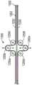
图11示出了根据一个实施方案的具有基于器械的插入架构的器械的侧视图。器械1200的设计和架构使得器械(例如,其轴)能够在较少依赖于机器人臂的移动进行插入的情况下沿插入轴线平移。11 shows a side view of an instrument with an instrument-based insertion architecture, according to one embodiment. The design and architecture of the
器械1200包括细长轴1202、连接到轴1202的端部执行器1212和耦接到轴1202的柄部1220。细长轴1202包括管状构件,该管状构件具有近侧部分1204和远侧部分1206。细长轴1202沿其外表面包括一个或多个通道或沟槽1208。在轴1202的剖视图中最可见的沟槽1208被配置为穿过其中接收一根或多根线材或缆线1230。因此,一根或多根缆线1230沿细长轴1202的外表面延伸。在其它实施方案中,缆线1230也可延伸穿过轴1202,如图21中的示意图所示。在一些实施方案中,延伸穿过轴1202的缆线1230未暴露。在一些实施方案中,这些缆线1230中的一根或多根缆线的操纵(例如,经由IDM 300)导致端部执行器1212的致动。The
端部执行器1212包括被设计成为向外科部位提供作用的一个或多个腹腔镜式部件、内窥镜式部件或腔内部件。例如,端部执行器1212可包括腕部、抓紧器、尖齿、夹钳、剪刀或夹具。在图11所示的本实施方案中,沿轴1202的外表面上的沟槽1208延伸的缆线1230中的一根或多根缆线致动端部执行器1212。一根或多根缆线1230从轴1202的近侧部分1204穿过柄部1220并且朝向轴1202的远侧部分1206延伸,在远侧部分1206处,一根或多根缆线1230致动端部执行器1212。The
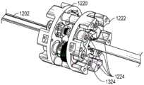
器械柄部1220(也可称为器械基部)通常可包括附接接口1222,该附接接口1222具有一个或多个机械输入端1224,例如插孔、滑轮或卷轴,该一个或多个机械输入端1224被设计成与(如图3所示的)IDM 300的附接接口310上的一个或多个扭矩耦接器314往复地配合。附接接口1222能够通过前安装、后安装和/或顶安装附接到IDM 300。当物理地连接、闩锁和/或耦接时,器械柄部1220的配合的机械输入端1224可与IDM 300的扭矩耦接器314共享旋转轴线,从而允许将扭矩从IDM 300传送到器械柄部1220。在一些实施方案中,扭矩耦接器314可包括被设计成与机械输入端上的插孔配合的花键。致动端部执行器1212的缆线1230接合柄部1220的插孔、滑轮或卷轴,使得扭矩从IDM 300到器械柄部1220的传送导致端部执行器的致动。The instrument handle 1220 (which may also be referred to as the instrument base) may generally include an
器械1200的一些实施方案包括控制端部执行器1212的致动的第一致动机构。此类第一致动机构的实施方案在图12中示意性地示出。此外,器械1200包括使得轴1202能够相对于柄部1220沿插入轴线平移的第二致动机构。此类第二致动机构的实施方案在图17中示出。有利地,第一致动机构与第二致动机构脱离,使得端部执行器1212的致动不受轴1202的平移影响,并且反之亦然。可结合到工具或器械1200中的第一致动机构和第二致动机构的实施方案在下文参考图12-图20更详细地描述。Some embodiments of the
图12示出了根据一个实施方案的用于致动端部执行器的第一致动机构的示意图。在一些实施方案中,第一致动机构提供N+1种腕部运动,其中N是由N+1根缆线提供的自由度的数量。用于致动端部执行器1212的第一致动机构包括延伸穿过至少一组滑轮1250的至少一根缆线或缆线段1230a。在本实施方案中,第一缆线或缆线段1230a延伸穿过滑轮构件1250a、1250b、1250c,而第二缆线或缆线段1230a延伸穿过滑轮构件1250d、1250e、1250f。至少一根缆线1230a在轴1202的近侧端部1205处或附近接地,然后延伸穿过至少一组滑轮1250(该至少一组滑轮1250位于柄部1220内),然后端接在端部执行器1212处。通过使每根缆线1230a在轴1202的近侧端部1205处或附近接地来使缆线总路径长度保持恒定,并且通过使滑轮(例如,滑轮构件1250b和1250e)相对于彼此移动(参见箭头)来进行相对长度改变,从而实现端部执行器1212的致动。在一些实施方案中,滑轮可经由对应机械输入端1224的线性或旋转运动来移动。此第一致动机构有利地准许器械轴1202相对于致动滑轮1250自由移动(这将通过下文所述的第二致动机构实现),从而允许包括另外的缆线以准许在端部执行器1212致动的同时插入和回缩器械轴1202。12 shows a schematic diagram of a first actuation mechanism for actuating an end effector, according to one embodiment. In some embodiments, the first actuation mechanism provides N+1 wrist movements, where N is the number of degrees of freedom provided by N+1 cables. The first actuation mechanism for actuating the
图13示出了根据一个实施方案的图11的器械的第一致动机构的放大侧视图。第一致动机构与图12所示的示意图相对应,并且被设计成引起端部执行器1212的致动,同时准许单独的第二致动机构使轴1202相对于柄部1220平移。如图13所示,柄部1220包括一组轴承、卷轴、滑轮或滑轮构件1250a、1250b、1250c、1250d、1250e(其中滑轮1250a、1250b、1250c对应于图12中的同一组滑轮)。缆线1230a延伸穿过滑轮1250a、1250d、1250b、1250e、1250c。机械输入端(在图13中识别为1224')的操纵引起滑轮1250d、1250b、1250e的旋转运动。滑轮1250d、1250b、1250e的旋转运动改变接收在柄部1220中的缆线1230的量,从而致动端部执行器。滑轮在缆线1230a上的旋转运动的作用在图15和图16中示出。根据旋转运动的方向,滑轮1250d、1250e可卷绕或“收起”柄部1220中的缆线1230,或者可退绕并“给出”柄部1220中的缆线1230a。无论哪种方式,缆线1230a的长度在柄部1220内改变,从而引起端部执行器1212的致动。虽然图13中的实施方案描绘了通过旋转运动修改的滑轮系统,但在其它实施方案中,滑轮系统可通过线性和/或旋转运动修改。此外,本领域的技术人员将会知道,柄部1220中的缆线1230a的量的长度变化还可改变缆线张力。Figure 13 shows an enlarged side view of the first actuation mechanism of the instrument of Figure 11, according to one embodiment. The first actuation mechanism corresponds to the schematic diagram shown in FIG. 12 and is designed to cause actuation of the
图14示出了根据一个实施方案的图11的器械的第一致动机构的放大透视图。从该视图可看到滑轮1250a-e的不同细节,包括滑轮1250a、1250c的卷轴。14 shows an enlarged perspective view of the first actuation mechanism of the instrument of FIG. 11 according to one embodiment. Various details of the
图15和图16示出了根据一个实施方案的图11的器械的滑轮构件1250e和缆线在致动滑轮构件前后的前视图。在机械输入端1224'上施加扭矩使滑轮1250e、1250b和1250d旋转。如图15所示,在致动滑轮1250e之前,缆线1230a可沿滑轮1250e的一侧延伸。如图16所示,在致动滑轮1250e之后,缆线1230a接着由滑轮卷绕和收起,从而增加柄部1220内的缆线1230a的量以引起端部执行器的致动。15 and 16 illustrate front views of the
虽然图11-图16中的实施方案公开了安装在旋转轴线上以改变相对缆线长度的一个或多个滑轮,但是在其它实施方案中,将滑轮安装在基于杆件、齿轮或轨道的系统上以调节位置是另外的选择。此外,沿工具的长度行进的球形花键旋转轴也可用于以机械远程方式传输力。While the embodiments in Figures 11-16 disclose one or more pulleys mounted on the axis of rotation to vary relative cable lengths, in other embodiments the pulleys are mounted on rod, gear or track based systems The above to adjust the position is another option. In addition, a spherically splined rotary shaft that runs along the length of the tool can also be used to transmit force in a mechanically remote manner.
图17示出了根据一个实施方案的包括用于轴平移的卷轴的第二致动机构的侧视图。第二致动机构被设计成使轴1202相对于柄部1220沿插入轴线平移。与致动端部执行器1212的第一致动机构类似,第二致动机构也可结合在柄部1220内。17 shows a side view of a second actuation mechanism including a spool for shaft translation, according to one embodiment. The second actuation mechanism is designed to translate the
第二致动机构包括接合一组卷轴1270a、1270b、1270c、1270d的缆线或缆线段1230b。缆线1230b的一个端部可附接在轴1202的近侧端部1205处或附近,而缆线1230b的另一个端部可附接在轴1202的远侧端部1207处或附近。缆线1230b延伸穿过这组卷轴1270a、1270b、1270c,其中卷轴1270b是绞盘。使柄部1220的机械输入端旋转引起绞盘的旋转,从而驱动缆线1230b进出绞盘。当缆线1230b被驱动进出绞盘时,这引起轴1202相对于柄部1220平移。有利地,通过向附接在轴1202的近侧端部和远侧端部处的缆线1230b施加足够的预张力,可使用摩擦力来驱动缆线1230b进出,从而使轴1202相对于柄部1220移动而不会滑动。The second actuation mechanism includes a cable or
在本实施方案中,绞盘1270b包括零游走绞盘。在其它实施方案中,诸如图18和图19所示,可将可允许缆线游走的绞盘结合到柄部1220中。零游走绞盘架构帮助管理缆线1230b围绕绞盘1270b的多次缠绕而在沟槽上无螺旋角以防止缆线跨绞盘1270b游走,这可能会影响总路径长度并且改变缆线中的张力。通过将另外的滑轮1270d放置在绞盘1270b旁边的斜面上,可实现重新定向到绞盘1270b上的平行路径,从而导致缆线1230b在绞盘1270b上无游走动作。In this embodiment, the
图18和图19呈现了图17所示的零游走绞盘的另选实施方案。在这些实施方案中,驱动轴插入的绞盘是可结合到第二致动机构的架构中的放大的绞盘1270e。在足够大的驱动绞盘1270e和足够小的插入行程的情况下,绞盘的旋转次数少。例如,在22mm驱动绞盘1270e和350mm插入行程的情况下,用于实现完全插入范围的绞盘1270e的旋转次数为5次旋转。如果缆线行进的距离与绞盘1270e的缆线游走范围相比足够大,则在插入期间的缆线上的偏离角的量和路径长度变化小到足以忽略不计。在一些实施方案中,偏离角可介于+/-2度之间。Figures 18 and 19 present an alternative embodiment of the zero-run winch shown in Figure 17 . In these embodiments, the drive shaft inserted capstan is an
图18示出了根据一个实施方案的使用单根缆线进行轴平移的另选卷轴的透视图。另选卷轴包括由单根缆线1230b接合的放大的绞盘1270e。在该实施方案中,为了致动驱动轴插入,单根缆线1230b具有足够大的包角以具有足够的绞盘摩擦来进行驱动。在一些实施方案中,单根缆线1230b是连续的并且围绕绞盘1270e缠绕多次(例如,3次、4次或更多次)以具有足够大的包角来驱动绞盘和插入。18 shows a perspective view of an alternative spool using a single cable for axis translation, according to one embodiment. An alternative reel includes an
图19示出了根据一个实施方案的使用多于一根缆线进行轴平移的另选卷轴的透视图。另选卷轴包括由单根缆线1230b的两个单独分段1230b'、1230b”接合的放大的绞盘1270e。分段1230b'、1230b”中的每一者端接在绞盘1270e上。与图18中的实施方案不同,本实施方案并不依赖于绞盘摩擦来驱动轴插入。在该实施方案中,缆线1230b螺旋连接到外部,然后在顶部和底部两者处端接到卷轴。图19所示的双端接方法的优点在于:它对于线缆张力的损失是有弹性的。由于双端接方法依赖于强制接合而不是摩擦,因此不会发生滑动。19 shows a perspective view of an alternative spool using more than one cable for axis translation, according to one embodiment. An alternative reel includes an
图20示出了根据一个实施方案的包括图18的卷轴的柄部的前视图。从该视图可看到卷轴(例如,绞盘1270e)在柄部1220内的一个可能位置。有利地,另外的卷轴和滑轮可设置在柄部1220内以致动端部执行器1212。例如,如图12所表示的用于端部执行器致动的滑轮系统可结合到图20中的柄部中。因此,柄部1220可结合用于端部执行器致动和/或驱动插入两者的多个机构。如图20所示,将缆线1230引导到绞盘1270e上的一个或多个滑轮跨柄部定位以增加缆线距离。如果缆线行进的距离与绞盘1270e的缆线游走范围相比足够大,则在插入期间的缆线上的偏离角的量和路径长度变化小到足以忽略不计。在一些实施方案中,有可能具有传统的螺旋绞盘并且使长度变化和偏离角保持为最小值。20 illustrates a front view of a handle including the spool of FIG. 18, according to one embodiment. One possible location for a reel (eg,
图21示出了显示根据一个实施方案的用于致动端部执行器和轴插入的另选架构的示意图。该架构结合了用于致动端部执行器的第一致动机构和用于轴插入的第二致动机构。与先前的实施方案类似,第一致动机构和第二致动机构脱离,使得端部执行器的致动不影响轴插入,并且反之亦然。然而,在本实施方案中,第一致动机构包括用于致动端部执行器的一根或多根缆线,该一根或多根缆线端接在插入卷轴(它也用作用于轴插入的第二致动机构的一部分)处,而不是像在图12中的实施方案中那样端接在轴的近侧部分和远侧部分上。由于该架构,在经由第二致动机构的轴插入期间,由插入卷轴卷绕的一根或多根缆线基本上由通过插入卷轴退绕的一根或多根缆线(在第一致动机构中用于致动端部执行器)的长度反向平衡。在经由第一致动机构的端部执行器致动期间,权衡脱离插入卷轴的缆线的路径长度。Figure 21 shows a schematic diagram showing an alternative architecture for actuating the end effector and shaft insertion, according to one embodiment. The architecture incorporates a first actuation mechanism for actuating the end effector and a second actuation mechanism for shaft insertion. Similar to the previous embodiment, the first actuation mechanism and the second actuation mechanism are disengaged so that actuation of the end effector does not affect shaft insertion, and vice versa. However, in this embodiment, the first actuation mechanism includes one or more cables for actuating the end effector, the one or more cables terminating at the insertion spool (which also serves as a part of the second actuation mechanism into which the shaft is inserted), rather than terminating on the proximal and distal portions of the shaft as in the embodiment in FIG. 12 . Due to this architecture, during insertion of the shaft via the second actuating mechanism, the cable or cables spooled by the insertion spool are substantially separated from the cable or cables unwound through the insertion spool (during the first coincidence The length of the actuator used to actuate the end effector) is counterbalanced. During actuation of the end effector via the first actuation mechanism, the path length of the cable exiting the insertion spool is weighed.
如图21所示,用于端部执行器致动和轴插入的另选架构包括具有近侧部分1304和远侧部分1306的轴1302,端部执行器位于远侧部分1306处。一个或多个卷轴1370a、1370b、1370c、1370d、1370e(它们是柄部的一部分)围绕轴1302定位。卷轴1370c包括插入卷轴。插入卷轴1370c在第一方向上的旋转引起相对于柄部在第一方向上(例如,在插入方向上)的轴平移,而插入卷轴1370c在第二方向上的旋转引起相对于柄部在第二方向上(例如,在回缩方向上)的轴平移。一根或多根缆线或缆线段1330a在一个端部上端接到端部执行器(例如,腕部)并且在另一个端部上端接到插入卷轴。在端接在轴1302的远侧部分1306处、附近或朝向远侧部分1306端接之前,一根或多根另外的缆线或缆线段1330b也在插入卷轴1370c处开始。As shown in Figure 21, an alternative architecture for end effector actuation and shaft insertion includes a
在本实施方案中,提供了第一致动机构,其中经由线性或旋转移动对一个或多个卷轴(例如,卷轴1370a、1370d)的操纵引起柄部内的一根或多根缆线1330a的长度变化。在一些实施方案中,柄部内的一根或多根缆线1330a的长度变化可包括柄部内的一根或多根缆线或缆线段的路径长度的变化。在该第一致动机构中,一根或多根缆线1330a可被视为“端部执行器”缆线。引起端部执行器的致动的柄部中的一根或多根缆线1330a的任何长度变化由一根或多根缆线1330b的长度反向平衡。In this embodiment, a first actuation mechanism is provided in which manipulation of one or more reels (eg,
在本实施方案中,提供了第二致动机构,其中经由线性或旋转移动对插入卷轴1370c的操纵引起柄部内的一根或多根缆线1330b的长度变化。在该第二致动机构中,一根或多根缆线1330b可被视为“插入”缆线。引起轴插入或回缩的柄部中的一根或多根缆线1330b的任何长度变化由一根或多根缆线1330a的长度反向平衡。在插入和回缩下,张力得以保持,因为在收起一根或多根插入缆线1330b时,一根或多根端部执行器缆线1330a的相等量被放出。一根或多根端部执行器缆线1330a的相对路径长度保持不变,因此端部执行器在插入下不移动。In this embodiment, a second actuation mechanism is provided wherein manipulation of the
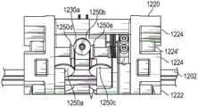
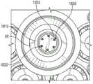
图22A示出了根据一个实施方案的结合有图21的用于致动端部执行器和轴插入的另选架构的器械的放大前视图。图22B示出了结合有图21的用于致动端部执行器和轴插入的另选架构的器械的顶部透视图。器械1300结合有图21所示的第一致动机构和第二致动机构,并且包括柄部1320,该柄部1320包括一个或多个机械输入端1324,每个机械输入端对应于一个或多个卷轴1370a-1370e,其中卷轴中的至少一个卷轴(1370c)包括插入卷轴。各自对应于单独的机械输入端1324的一根或多根缆线或缆线段1330a'、1330a”、1330a”’和1330a””端接在驱动卷轴1370c处。这些缆线1330a'、1330a”、1330a”’和1330a””中的每一者可类似于一根或多根缆线1330a(在图21中的示意图中示出)与一个或多个卷轴接合。在第一致动机构中,这些缆线可用作端部执行器缆线,使得对其对应机械输入端1324的操纵引起柄部内的缆线的长度变化。在一些实施方案中,柄部内的一根或多根缆线的长度变化可包括柄部内的一根或多根缆线或缆线段的路径长度的变化。在一些实施方案中,改变柄部内的缆线的路径长度。在一些情况下,致动端部执行器的柄部1320内的一根或多根缆线1330a'、1330a”、1330a”’和1330a””的长度变化由类似于图21中的类似参考缆线1330b的缆线1330b的长度反向平衡。在其它情况下,在纯粹的端部执行器致动下,柄部中的缆线1330b的长度不改变。在第二致动机构中,缆线1330b可用作插入缆线,使得对其对应机械输入端1324的操纵引起缆线1330b围绕插入卷轴1370c卷绕。引起轴插入的围绕插入卷轴1370c卷绕的缆线1330b的量由退绕的一根或多根缆线1330a'、1330a”、1330a”’和1330a””的长度反向平衡。22A illustrates an enlarged front view of an instrument incorporating the alternative architecture of FIG. 21 for actuating an end effector and shaft insertion, according to one embodiment. 22B shows a top perspective view of an instrument incorporating the alternative architecture of FIG. 21 for actuating the end effector and shaft insertion.
图23示出了根据一个实施方案的器械的柄部和轴的顶部透视图。轴1202可相对于柄部1220平移。从该视图可看到在旋转时致动端部执行器的一个或多个机械输入端1224。此外,可看到在旋转时允许轴1202相对于柄部1220沿插入轴线平移的一个或多个机械输入端1324。附接接口1222包括一个或多个机械输入端1224、1324,例如插孔、滑轮或卷轴,该一个或多个机械输入端1224、1324被设计成与(如图3所示的)IDM 300的附接接口310上的一个或多个扭矩耦接器314往复地配合。Figure 23 shows a top perspective view of the handle and shaft of an instrument according to one embodiment. The
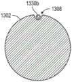
图24A示出了利用图12所示的插入架构的器械轴的横截面的示意图,而图24B示出了利用图21所示的另选插入架构的器械轴的横截面的示意图。虽然不可见,但是图24A和24B中的横截面中的每一者包括从中延伸穿过的开口或内腔。如图24A所示,图12的插入架构产生延伸穿过沿轴1202的外表面延伸的沟槽或通道1208的一根或多根缆线1230。相比之下,如图24B所示,图21的插入架构产生延伸穿过沿轴1202的外表面延伸的较少沟槽或通道1308(此处为单个通道)的一根或多根缆线1330b。这是因为在图21的另选架构中,缆线更倾向于在轴1302的主体内延伸。例如,在轴1302的外部上不存在端部执行器缆线。在较少缆线在轴1302的外部上延伸的情况下,图21中的架构可产生具有在外表面上延伸的较少沟槽或通道的总体更光滑的轴表面。24A shows a schematic diagram of a cross-section of an instrument shaft utilizing the insertion architecture shown in FIG. 12 , while FIG. 24B shows a schematic diagram of a cross-section of an instrument shaft utilizing the alternative insertion architecture shown in FIG. 21 . Although not visible, each of the cross-sections in Figures 24A and 24B include an opening or lumen extending therethrough. As shown in FIG. 24A , the insertion architecture of FIG. 12 produces one or
VIII.用于特定器械的插入架构的实施方案VIII. Embodiments of Insertion Architectures for Specific Devices
上述架构(例如,在图12和图21中示出)可用于致动端部执行器并且适应器械插入。此外,这些架构可结合到特定类型的器械中以有助于外科手术。The architectures described above (eg, shown in FIGS. 12 and 21 ) can be used to actuate the end effector and accommodate instrument insertion. Additionally, these architectures can be incorporated into certain types of instruments to facilitate surgical procedures.
一种此类器械是血管闭合器。利用血管闭合器,可驱动刀或切割器穿过以切割组织。在一些实施方案中,刀的运动是旋转的。在其它实施方案中,刀的运动是平移的。图25-图27示出了可结合到血管闭合器器械中以驱动刀穿过血管闭合器的不同架构。这些附图中所示的架构类似于图12所示的架构和相关机构,但在其它实施方案中,架构可类似于图21所示的架构和相关机构。One such device is a vascular occluder. With a vessel closure, a knife or cutter can be driven through to cut tissue. In some embodiments, the movement of the knife is rotational. In other embodiments, the movement of the knife is translational. Figures 25-27 illustrate different architectures that can be incorporated into a vessel closure device to drive a knife through a vessel closure device. The architecture shown in these figures is similar to that shown in FIG. 12 and related mechanisms, but in other embodiments, the architecture may be similar to that shown in FIG. 21 and related mechanisms.
图25-图27示出了显示用于在血管闭合器中驱动刀的不同架构的示意图。架构在缆线之间形成路径长度的差别,并且将该差别的路径长度变化转变成刀的线性运动。在图25和图26的实施方案中,两根缆线1430a、1430b被置于反向张力下,而在图27的实施方案中,单根缆线1430和弹簧1490用于反向张力。在其中两根缆线被置于反向张力下的实施方案中,通过在同一输入轴线上但在相反方向上具有两个差别(例如,一根是解绕缆线,而另一根是缠绕缆线)来实现刀的线性运动。双对置缆线方法还利用重新定向滑轮来封闭张力环,并且这可安装在轴的近侧端部处或附近或者安装在轴的远侧端部处或附近(分别在图25和图26中示出)。一旦具有被拉入和拉出的缆线,就可将刀耦接到缆线的部段以形成刀的进出运动。Figures 25-27 show schematic diagrams showing different architectures for driving a blade in a vessel closure. The architecture creates a difference in path length between the cables and translates this difference in path length variation into linear motion of the knife. In the embodiment of Figures 25 and 26, two
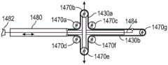
图25示出了显示用于在血管闭合器1480中驱动刀1482的架构的示意图。该架构包括第一缆线1430a和第二缆线1430b,其中第一缆线1430a和第二缆线1430b在反向张力下。该架构还包括由第一缆线1430a接合的一个或多个卷轴或滑轮构件1470a、1470b、1470c,以及由第二缆线1430b接合的一个或多个卷轴或滑轮构件1470d、1470e、1470f,以及封闭张力环的重新定向卷轴或滑轮1470g。重新定向滑轮1470g定位在轴的近侧部分处或附近。在第一缆线1430a和第二缆线1430b彼此在反向张力下的情况下,可经由连接器诸如细长构件1484将刀1482耦接到缆线(例如,第一缆线1430a)的部段,从而形成刀1482相对于血管闭合器1480的进出运动。在一些实施方案中,细长构件1484包括推杆。在其它实施方案中,细长构件1484承受驱动压缩力而不屈曲。25 shows a schematic diagram showing the architecture for driving the
图26示出了显示用于在血管闭合器中驱动刀的另选架构的示意图。该架构类似于图25所示的架构;然而,在本实施方案中,重新定向滑轮定位在轴的远侧部分处或附近。Figure 26 shows a schematic diagram showing an alternative architecture for driving a blade in a vessel closure. The architecture is similar to that shown in Figure 25; however, in this embodiment, the redirection pulley is positioned at or near the distal portion of the shaft.
图27示出了显示用于在血管闭合器中驱动刀的又一个另选架构的示意图。与图25和图26中的先前实施方案不同,本实施方案中的架构利用与弹簧1490在反向张力下的单根缆线1430。该架构还包括由第一缆线1430a接合的一个或多个卷轴或滑轮构件1470a、1470b、1470c。在缆线1430与弹簧1490在反向张力下的情况下,刀1482可耦接到缆线1430的部段,从而形成刀1482相对于血管闭合器1480的进出运动。Figure 27 shows a schematic diagram showing yet another alternative architecture for driving a blade in a vessel closure. Unlike the previous embodiments in FIGS. 25 and 26 , the architecture in this embodiment utilizes a
可用作插入器械的另一个装置是相机。相机可用于内窥镜式外科手术。该架构可根据相机是刚性相机还是铰接相机而变化,对于该铰接相机,将必须提供用于铰接的致动。Another device that can be used as an insertion instrument is a camera. Cameras can be used for endoscopic surgery. The architecture may vary depending on whether the camera is a rigid camera or an articulating camera for which actuation for the articulation will have to be provided.
图28示出了显示用于使刚性相机成为插入器械的架构的示意图。相机1500包括通过轴1502连接到相机柄部1530的远侧图像有效载荷,该相机柄部1530具有接口按钮和从接口按钮伸出的缆线。缆线1530被接收在形成于轴1502的外部上的通道或沟槽中,而插入柄部1520围绕轴1502定位。这实际上向内窥镜添加了第二柄部,从而实现插入能力。缆线1530延伸穿过一个或多个卷轴1570a、1570b、1570c。在本实施方案中,卷轴1570b可以是绞盘。在一些实施方案中,绞盘可包括零游走绞盘(如图17所示),而在其它实施方案中,绞盘可允许缆线游走(如图18和图19所示)。经由绞盘机构,相机能够沿插入轴线平移。在一些实施方案中,核心有效载荷保持与刚性窥镜相同的密封架构,因此可预期用相同的方法来消毒。对于刚性窥镜,这意味着它可进行高压消毒。从消毒视角看,另外的插入柄部1520也可看起来像器械,并且也可进行高压消毒。Figure 28 shows a schematic diagram showing an architecture for making a rigid camera an insertion instrument.
虽然图28示出了用于使刚性相机成为插入器械的架构,但是铰接相机存在另外的复杂性,因为将向相机添加机构以实现铰接。对于铰接相机,可提供一根或多根缆线(例如,致动缆线或腕部缆线)以适应铰接移动。相机也可容纳在密封区域中,使得如果要使一根或多根缆线在外部上延伸,则也可为不包括一根或多根缆线的相机形成密封隔室。在该架构的情况下,一些颗粒和碎片可能进入密封区域内的小空间中。在一些实施方案中,为了防止污染,一种解决方案可以是在密封相机区域内添加两个铰接马达,而不是依赖于IDM进行铰接运动。这通过从管的外部取出缆线并且将它们放入密封内部而大大简化了相机部件的清洁和密封。在密封相机内添加两个铰接马达的另一个有益效果在于:一将相机插接到视觉盒子中,就可控制相机的铰接。这实现像在安装或移除期间保持相机笔直并且在脱离机器人使用期间能够使相机从相机柄部铰接以环顾四周的特征。然后,从消毒视角看,这使得铰接相机看起来很像刚性相机,使得有可能进行高压消毒。While Figure 28 shows an architecture for making a rigid camera an insertion instrument, articulating the camera presents additional complications as mechanisms will be added to the camera to achieve articulation. For articulating cameras, one or more cables (eg, actuation cables or wrist cables) may be provided to accommodate articulating movement. The camera can also be accommodated in the sealed area, so that if one or more cables are to extend on the outside, a sealed compartment can also be formed for a camera that does not include one or more cables. With this architecture, some particles and debris may get into the small spaces within the sealed area. In some embodiments, to prevent contamination, one solution may be to add two articulation motors within the sealed camera area, rather than relying on the IDM for articulation. This greatly simplifies the cleaning and sealing of camera components by removing the cables from the outside of the tube and placing them inside the seal. Another benefit of adding two articulation motors within a sealed camera is that the articulation of the camera can be controlled as soon as the camera is plugged into the vision box. This enables features like keeping the camera straight during installation or removal and being able to articulate the camera from the camera handle to look around during use away from the robot. Then, from a sterilization perspective, this makes the articulated camera look a lot like a rigid camera, making it possible to autoclave.
如果相机不能进行高压消毒,则可能需要使密封相机核心和插入部段分离以用于清洁和插入。这是因为期望对插入柄部进行高压消毒以实现可靠的消毒。图29示出了允许相机与插入柄部分离、从而允许更好地消毒的第一插入架构,而图30和图31示出了允许相机与插入柄部分离、从而允许更好地消毒的第二插入架构。If the camera cannot be autoclaved, it may be necessary to separate the sealed camera core and insertion section for cleaning and insertion. This is because it is desirable to autoclave the insertion handle for reliable sterilization. Figure 29 shows a first insertion architecture that allows separation of the camera from the insertion handle, allowing for better sterilization, while Figures 30 and 31 show a first insertion architecture that allows separation of the camera from the insertion handle, allowing for better sterilization Two-insert architecture.
图29示出了允许相机与插入柄部分离的第一插入架构。该架构具有可高压消毒的插入柄部1620,该插入柄部1620闩锁到IDM上并且可与相机核心1600分离。相机核心1600包括延伸穿过柄部1620的轴1602。柄部1620包括延伸穿过卷轴1670a、1670b、1670c、1670d的一根或多根线材1630a、1630b。在本实施方案中,卷轴1670b包括绞盘。在一些实施方案中,卷轴1670b包括导螺杆。在一些实施方案中,绞盘是零游走绞盘(如图17所示),而在其它实施方案中,绞盘允许缆线游走。插入柄部1620可经由连接器1640可移除地附接到相机核心1600。在一些实施方案中,连接器1640包括托架。在其它实施方案中,连接器1640包括相机所闩锁到的竖直板。当插入柄部1620可移除地附接到相机核心1600时,它们各自能够分离以用于清洁。Figure 29 shows a first insertion structure that allows the camera to be separated from the insertion handle. The architecture has an
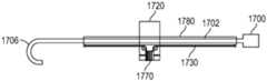
图30和图31示出了允许相机与插入柄部分离的第二架构。在本实施方案中,提供了外套管1780,该外套管1780具有附接到其的插入缆线1730,并且可穿过外套管1780装载相机1700以用于手术。图30示出了与外套管1780拆离和分离的相机1700,而图31示出了装载到外套管1780中的相机1700。为了将相机1700装载到外套管中,相机1700的远侧末端1706和轴1702穿过外套管1780。外套管1780连接到柄部1720,该柄部1720容纳呈绞盘形式的卷轴1770。该架构具有以下益处:如果需要,则保持相机1700与插入柄部1720分离,使得可容易地清洁两个部件。此外,相机1700在使用中保持薄型,因为它将配合到外套管1780中。当插入柄部1720可移除地附接到相机核心1700时,它们各自能够分离以用于清洁。Figures 30 and 31 show a second architecture that allows the camera to be separated from the insertion handle. In this embodiment, an
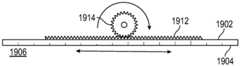
图32示出了显示根据另一个实施方案的用于轴平移的另选架构的图。在本实施方案,器械包括具有近侧部分1904和远侧部分1906的轴1902。轴1902的插入可由齿条齿1912和小齿轮1914驱动,其中小齿轮1914的旋转导致齿条齿1912和耦接到齿条齿1912的轴1902的平移。在一些实施方案中,齿条齿1912定位在器械轴1902上,而小齿轮1914定位在器械柄部的壳体内。马达驱动器可用于使轴1902相对于柄部平移。在一些实施方案中,除了摆线针齿条齿廓之外,还可使用正齿轮。在一些实施方案中,齿条齿1912和小齿轮1914可单独用来引起轴1902的插入或平移。在其它实施方案中,齿条齿1912和小齿轮1914可伴随并补充上述插入机构中的任一种。齿条齿1912和小齿轮1914可与任何上述类型的器械一起用来提供器械轴相对于柄部的线性插入。32 shows a diagram showing an alternative architecture for axis translation according to another embodiment. In this embodiment, the instrument includes a
IX.外科工具密封IX. Surgical Tool Seals
当执行外科手术诸如腹腔镜式手术时,外科医生使用吹入法。这意味着插入患者体内的插管抵靠外科工具轴密封以保持患者身体内部的正压。密封件可耦接到外科工具轴以防止空气从患者的身体泄漏。这些密封件通常被设计成适应具有圆形横截面的工具。可能难以将相同的密封件应用到具有非圆形形状且在轴的外表面上具有凹形特征的工具,因为由这些表面形成的通道可允许在工具密封件处释放空气压力。例如,具有基于器械的插入架构的器械可具有带沟槽1208的横截面(如图24A所示),在沟槽1208处,空气可从患者泄漏。Surgeons use insufflation when performing surgical procedures, such as laparoscopic procedures. This means that the cannula inserted into the patient is sealed against the surgical tool shaft to maintain positive pressure inside the patient's body. A seal may be coupled to the surgical tool shaft to prevent leakage of air from the patient's body. These seals are generally designed to accommodate tools with circular cross-sections. It can be difficult to apply the same seal to a tool that has a non-circular shape with concave features on the outer surface of the shaft because the channels formed by these surfaces can allow air pressure to be released at the tool seal. For example, an instrument with an instrument-based insertion architecture can have a cross-section (as shown in Figure 24A) with
为了解决该挑战,可提供包括多个密封件的系统以防止患者体内的空气泄漏。具体地,可提供与具有圆形外部形状的插管密封件一起工作的新颖密封件,这对于具有圆形横截面的器械是惯常的。新颖密封件可穿过圆形插管密封件,从而提供一致的旋转密封。新颖密封件将有利地使任何旋转运动和线性运动离散以形成在那里形成密封的两个边界。通过具有中间工具密封件来实现离散化。To address this challenge, systems including multiple seals may be provided to prevent air leakage within the patient. In particular, novel seals can be provided that work with cannula seals having a circular outer shape, which is customary for instruments with circular cross-sections. The novel seal passes through the circular cannula seal to provide a consistent rotational seal. The novel seal will advantageously discretize any rotational and linear motion to form the two boundaries where the seal is formed. Discretization is achieved by having an intermediate tool seal.
图33示出了具有多个密封件以防止来自患者的空气泄漏的器械的侧剖视图。图34示出了具有多个密封件的器械的前剖视图。器械1200插入插管50中,并且类似于图11所示的具有基于器械的插入架构的器械。器械可包括可相对于柄部1220平移的轴1202。轴1202可具有沿其外表面延伸的一个或多个通道或沟槽1208,从而形成可允许空气从患者泄漏的通道。33 shows a side cross-sectional view of an instrument with multiple seals to prevent air leakage from a patient. Figure 34 shows a front cross-sectional view of an instrument with multiple seals.
为了防止空气泄漏,多密封件系统有利地耦接到器械。在一些实施方案中,多密封件系统包括第一密封件1810和第二密封件1820,它们可结合工作以降低空气泄漏的风险。在一些实施方案中,第一密封件1810和第二密封件1820是同轴的。如图32所示,第二密封件1820可被接收在第一密封件1810的内部中。第一密封件1810可具有带圆形外周边和圆形内周边的横截面,而第二密封件1820可具有带圆形外周边和内周边的横截面,该内周边具有内部突出部、突片或凸块1822,如图34所示。具有带内部突出部的第二密封件1820的优点在于:内部突出部可填充可沿器械轴1202的外部延伸的空隙,诸如沟槽1208,从而降低在外科手术期间空气从患者泄漏的风险。To prevent air leakage, a multiple seal system is advantageously coupled to the instrument. In some embodiments, the multiple seal system includes a
多密封件有利地使旋转运动和线性运动离散以形成在那里形成密封的两个边界。第二密封件1820因其内部突出部1822而可沿器械轴1202的外部沟槽滑动,从而形成用于器械轴运动的滑动线性密封件。本领域的技术人员将会知道,虽然第二密封件1820被示出为具有倒圆并且围绕内周边基本上对称地间隔开的多个内部突出部,但是第二密封件1820的内部部分也可采取其它形状,只要模制工艺使第二密封件1820的内部与器械轴1202的外表面基本上匹配即可。当被接收在器械1200的沟槽1208中时,第二密封件1820的内凸块1822中的每一者形成旋转密封点1824。这些旋转密封点允许器械1200和第二密封件1820旋转地锁定并且在器械轴1202旋转时一起旋转。虽然本实施方案示出了具有双密封件的多密封件,但是在其它实施方案中,三个、四个或更多个密封件可一起工作以降低外科手术期间空气从患者泄漏的风险。Multiple seals advantageously discretize rotational and linear motion to form two boundaries where a seal is formed. The
X.另选注意事项X. Alternative Considerations
在阅读本公开时,本领域的技术人员将通过本文所公开的原理来理解另外的另选结构和功能设计。因此,虽然已经例示并描述了特定实施方案和应用,但是应当理解,所公开的实施方案不限于本文所公开的精确构造和部件。对于本领域的技术人员将显而易见的是,可在不脱离所附权利要求中限定的实质和范围的情况下对本文所公开的方法和设备的布置、操作和细节进行各种修改、改变和变型。Upon reading this disclosure, those skilled in the art will appreciate additional alternative structural and functional designs from the principles disclosed herein. Therefore, while specific embodiments and applications have been illustrated and described, it is to be understood that the disclosed embodiments are not limited to the precise constructions and components disclosed herein. It will be apparent to those skilled in the art that various modifications, changes and variations can be made in the arrangement, operation and details of the methods and apparatus disclosed herein without departing from the spirit and scope as defined in the appended claims .
如本文所用,对“一个实施方案”或“实施方案”的任何引用是指结合实施方案描述的特定元件、特征、结构或特性包括在至少一个实施方案中。在说明书中各处出现的短语“在一个实施方案中”并不一定全部是指相同的实施方案。As used herein, any reference to "one embodiment" or "an embodiment" means that a particular element, feature, structure or characteristic described in connection with the embodiment is included in at least one embodiment. The appearances of the phrase "in one embodiment" in various places in the specification are not necessarily all referring to the same embodiment.
一些实施方案可使用表达“耦接”和“连接”连同其衍生词来描述。例如,一些实施方案可使用术语“耦接”来描述,以指示两个或更多个元件直接物理接触或电接触。然而,术语“耦接”还可意味着两个或更多个元件彼此不是直接接触,而是彼此配合或相互作用。除非另有明确说明,否则实施方案不限于此上下文。Some embodiments may be described using the expressions "coupled" and "connected" along with their derivatives. For example, some embodiments may be described using the term "coupled" to indicate that two or more elements are in direct physical or electrical contact. However, the term "coupled" may also mean that two or more elements are not in direct contact with each other, but rather cooperate or interact with each other. Embodiments are not limited in this context unless explicitly stated otherwise.
如本文所用,术语“包括”(comprises、comprising、includes、including)、“具有”(has、having)或其任何其它变型均旨在涵盖非排他性的包括。例如,包括一系列元件的过程、方法、制品或设备不一定仅限于那些元件,而是可包括此类过程、方法、制品或设备未明确列出或固有的其它元件。此外,除非明确地指明相反,否则“或”是指包括性的或而不是指排他性的或。例如,条件A或B由以下任一项满足:A为真(或存在)而B为假(或不存在),A为假(或不存在)而B为真(或存在),以及A和B均为真(或存在)。As used herein, the terms "comprises," comprising, includes, including, "has," or any other variation thereof are intended to encompass non-exclusive includes. For example, a process, method, article of manufacture or apparatus comprising a series of elements is not necessarily limited to only those elements, but may include other elements not expressly listed or inherent in such process, method, article of manufacture or apparatus. Furthermore, unless expressly stated to the contrary, "or" refers to an inclusive or rather than an exclusive or. For example, a condition A or B is satisfied by either: A is true (or present) and B is false (or absent), A is false (or absent) and B is true (or present), and A and B is true (or exists).
此外,采用对“一个”或“一种”的使用来描述本文的实施方案的元件和部件。这样做仅出于方便的目的并且给出本发明的一般含义。该描述应理解为包括一个或至少一个,并且除非明显地另有所指,单数也包括复数。Furthermore, the use of "a" or "an" is employed to describe elements and components of the embodiments herein. This is done for convenience only and to give the general meaning of the invention. This description should be read to include one or at least one and the singular also includes the plural unless it is clear that it is meant otherwise.
Claims (27)
Translated fromChineseApplications Claiming Priority (3)
| Application Number | Priority Date | Filing Date | Title |
|---|---|---|---|
| US201762597385P | 2017-12-11 | 2017-12-11 | |
| US62/597385 | 2017-12-11 | ||
| PCT/US2018/064789WO2019118368A1 (en) | 2017-12-11 | 2018-12-10 | Systems and methods for instrument based insertion architectures |
Publications (1)
| Publication Number | Publication Date |
|---|---|
| CN111770736Atrue CN111770736A (en) | 2020-10-13 |
Family
ID=66734841
Family Applications (1)
| Application Number | Title | Priority Date | Filing Date |
|---|---|---|---|
| CN201880079994.7APendingCN111770736A (en) | 2017-12-11 | 2018-12-10 | Systems and methods for instrument-based insertion architectures |
Country Status (8)
| Country | Link |
|---|---|
| US (4) | US10470830B2 (en) |
| EP (1) | EP3723655A4 (en) |
| JP (2) | JP7080986B2 (en) |
| KR (1) | KR102462568B1 (en) |
| CN (1) | CN111770736A (en) |
| BR (1) | BR112020011444A2 (en) |
| MX (1) | MX2020006069A (en) |
| WO (1) | WO2019118368A1 (en) |
Cited By (1)
| Publication number | Priority date | Publication date | Assignee | Title |
|---|---|---|---|---|
| CN114680953A (en)* | 2020-12-30 | 2022-07-01 | 炳硕生医股份有限公司 | Medical device for manipulating surgical tools |
Families Citing this family (227)
| Publication number | Priority date | Publication date | Assignee | Title |
|---|---|---|---|---|
| US8414505B1 (en) | 2001-02-15 | 2013-04-09 | Hansen Medical, Inc. | Catheter driver system |
| WO2005087128A1 (en) | 2004-03-05 | 2005-09-22 | Hansen Medical, Inc. | Robotic catheter system |
| JP2009500086A (en) | 2005-07-01 | 2009-01-08 | ハンセン メディカル,インク. | Robotic guide catheter system |
| US9232959B2 (en) | 2007-01-02 | 2016-01-12 | Aquabeam, Llc | Multi fluid tissue resection methods and devices |
| US12290277B2 (en) | 2007-01-02 | 2025-05-06 | Aquabeam, Llc | Tissue resection with pressure sensing |
| ES2769535T3 (en) | 2008-03-06 | 2020-06-26 | Aquabeam Llc | Tissue ablation and cauterization with optical energy carried in a fluid stream |
| US9254123B2 (en) | 2009-04-29 | 2016-02-09 | Hansen Medical, Inc. | Flexible and steerable elongate instruments with shape control and support elements |
| US8672837B2 (en) | 2010-06-24 | 2014-03-18 | Hansen Medical, Inc. | Methods and devices for controlling a shapeable medical device |
| US20120071752A1 (en) | 2010-09-17 | 2012-03-22 | Sewell Christopher M | User interface and method for operating a robotic medical system |
| US20130030363A1 (en) | 2011-07-29 | 2013-01-31 | Hansen Medical, Inc. | Systems and methods utilizing shape sensing fibers |
| EP3351196A1 (en) | 2012-02-29 | 2018-07-25 | Procept Biorobotics Corporation | Automated image-guided tissue resection and treatment |
| US10383765B2 (en) | 2012-04-24 | 2019-08-20 | Auris Health, Inc. | Apparatus and method for a global coordinate system for use in robotic surgery |
| US20130317519A1 (en) | 2012-05-25 | 2013-11-28 | Hansen Medical, Inc. | Low friction instrument driver interface for robotic systems |
| US20140005640A1 (en) | 2012-06-28 | 2014-01-02 | Ethicon Endo-Surgery, Inc. | Surgical end effector jaw and electrode configurations |
| US20140148673A1 (en) | 2012-11-28 | 2014-05-29 | Hansen Medical, Inc. | Method of anchoring pullwire directly articulatable region in catheter |
| US10231867B2 (en) | 2013-01-18 | 2019-03-19 | Auris Health, Inc. | Method, apparatus and system for a water jet |
| US10149720B2 (en) | 2013-03-08 | 2018-12-11 | Auris Health, Inc. | Method, apparatus, and a system for facilitating bending of an instrument in a surgical or medical robotic environment |
| US9057600B2 (en) | 2013-03-13 | 2015-06-16 | Hansen Medical, Inc. | Reducing incremental measurement sensor error |
| US9566414B2 (en) | 2013-03-13 | 2017-02-14 | Hansen Medical, Inc. | Integrated catheter and guide wire controller |
| US11213363B2 (en) | 2013-03-14 | 2022-01-04 | Auris Health, Inc. | Catheter tension sensing |
| US9326822B2 (en) | 2013-03-14 | 2016-05-03 | Hansen Medical, Inc. | Active drives for robotic catheter manipulators |
| US20140277334A1 (en) | 2013-03-14 | 2014-09-18 | Hansen Medical, Inc. | Active drives for robotic catheter manipulators |
| US9173713B2 (en) | 2013-03-14 | 2015-11-03 | Hansen Medical, Inc. | Torque-based catheter articulation |
| US20140276936A1 (en) | 2013-03-15 | 2014-09-18 | Hansen Medical, Inc. | Active drive mechanism for simultaneous rotation and translation |
| US9452018B2 (en) | 2013-03-15 | 2016-09-27 | Hansen Medical, Inc. | Rotational support for an elongate member |
| US10849702B2 (en) | 2013-03-15 | 2020-12-01 | Auris Health, Inc. | User input devices for controlling manipulation of guidewires and catheters |
| US9014851B2 (en) | 2013-03-15 | 2015-04-21 | Hansen Medical, Inc. | Systems and methods for tracking robotically controlled medical instruments |
| US10376672B2 (en) | 2013-03-15 | 2019-08-13 | Auris Health, Inc. | Catheter insertion system and method of fabrication |
| US9271663B2 (en) | 2013-03-15 | 2016-03-01 | Hansen Medical, Inc. | Flexible instrument localization from both remote and elongation sensors |
| US9283046B2 (en) | 2013-03-15 | 2016-03-15 | Hansen Medical, Inc. | User interface for active drive apparatus with finite range of motion |
| US9408669B2 (en) | 2013-03-15 | 2016-08-09 | Hansen Medical, Inc. | Active drive mechanism with finite range of motion |
| US9629595B2 (en) | 2013-03-15 | 2017-04-25 | Hansen Medical, Inc. | Systems and methods for localizing, tracking and/or controlling medical instruments |
| US20140276647A1 (en) | 2013-03-15 | 2014-09-18 | Hansen Medical, Inc. | Vascular remote catheter manipulator |
| US11020016B2 (en) | 2013-05-30 | 2021-06-01 | Auris Health, Inc. | System and method for displaying anatomy and devices on a movable display |
| WO2014201165A1 (en) | 2013-06-11 | 2014-12-18 | Auris Surgical Robotics, Inc. | System for robotic assisted cataract surgery |
| US10426661B2 (en) | 2013-08-13 | 2019-10-01 | Auris Health, Inc. | Method and apparatus for laser assisted cataract surgery |
| CN109602495B (en) | 2013-08-15 | 2021-05-11 | 直观外科手术操作公司 | Instrument sterile adapter drive features |
| US10016244B2 (en)* | 2013-08-15 | 2018-07-10 | Intuitive Surgical Operations, Inc. | Robotic instrument driven element |
| EP3708105B1 (en) | 2013-08-15 | 2022-02-09 | Intuitive Surgical Operations, Inc. | Preloaded surgical instrument interface |
| CN108784838B (en) | 2013-08-15 | 2021-06-08 | 直观外科手术操作公司 | Instrument sterile adapter drive interface |
| EP3243476B1 (en) | 2014-03-24 | 2019-11-06 | Auris Health, Inc. | Systems and devices for catheter driving instinctiveness |
| US10046140B2 (en) | 2014-04-21 | 2018-08-14 | Hansen Medical, Inc. | Devices, systems, and methods for controlling active drive systems |
| US10569052B2 (en) | 2014-05-15 | 2020-02-25 | Auris Health, Inc. | Anti-buckling mechanisms for catheters |
| US9744335B2 (en) | 2014-07-01 | 2017-08-29 | Auris Surgical Robotics, Inc. | Apparatuses and methods for monitoring tendons of steerable catheters |
| US10792464B2 (en) | 2014-07-01 | 2020-10-06 | Auris Health, Inc. | Tool and method for using surgical endoscope with spiral lumens |
| US9561083B2 (en) | 2014-07-01 | 2017-02-07 | Auris Surgical Robotics, Inc. | Articulating flexible endoscopic tool with roll capabilities |
| EP3200718A4 (en) | 2014-09-30 | 2018-04-25 | Auris Surgical Robotics, Inc | Configurable robotic surgical system with virtual rail and flexible endoscope |
| US10499999B2 (en) | 2014-10-09 | 2019-12-10 | Auris Health, Inc. | Systems and methods for aligning an elongate member with an access site |
| US10314463B2 (en) | 2014-10-24 | 2019-06-11 | Auris Health, Inc. | Automated endoscope calibration |
| US11819636B2 (en) | 2015-03-30 | 2023-11-21 | Auris Health, Inc. | Endoscope pull wire electrical circuit |
| US20160287279A1 (en) | 2015-04-01 | 2016-10-06 | Auris Surgical Robotics, Inc. | Microsurgical tool for robotic applications |
| WO2016164824A1 (en) | 2015-04-09 | 2016-10-13 | Auris Surgical Robotics, Inc. | Surgical system with configurable rail-mounted mechanical arms |
| US9622827B2 (en) | 2015-05-15 | 2017-04-18 | Auris Surgical Robotics, Inc. | Surgical robotics system |
| US10959788B2 (en)* | 2015-06-03 | 2021-03-30 | Covidien Lp | Offset instrument drive unit |
| CN108348133B (en) | 2015-09-09 | 2020-11-13 | 奥瑞斯健康公司 | Instrument Manipulators for Surgical Robotic Systems |
| JP6824967B2 (en) | 2015-09-18 | 2021-02-03 | オーリス ヘルス インコーポレイテッド | Tubular net navigation |
| US10575754B2 (en) | 2015-09-23 | 2020-03-03 | Covidien Lp | Catheter having a sensor and an extended working channel |
| ITUB20155057A1 (en) | 2015-10-16 | 2017-04-16 | Medical Microinstruments S R L | Robotic surgery set |
| US9949749B2 (en) | 2015-10-30 | 2018-04-24 | Auris Surgical Robotics, Inc. | Object capture with a basket |
| US10231793B2 (en) | 2015-10-30 | 2019-03-19 | Auris Health, Inc. | Object removal through a percutaneous suction tube |
| US9955986B2 (en) | 2015-10-30 | 2018-05-01 | Auris Surgical Robotics, Inc. | Basket apparatus |
| US10143526B2 (en) | 2015-11-30 | 2018-12-04 | Auris Health, Inc. | Robot-assisted driving systems and methods |
| US10932861B2 (en) | 2016-01-14 | 2021-03-02 | Auris Health, Inc. | Electromagnetic tracking surgical system and method of controlling the same |
| US10932691B2 (en) | 2016-01-26 | 2021-03-02 | Auris Health, Inc. | Surgical tools having electromagnetic tracking components |
| WO2017156070A1 (en) | 2016-03-09 | 2017-09-14 | Intuitive Surgical Operations, Inc. | Force transmission mechanism for surgical instrument, and related devices, systems, and methods |
| US11324554B2 (en) | 2016-04-08 | 2022-05-10 | Auris Health, Inc. | Floating electromagnetic field generator system and method of controlling the same |
| US10454347B2 (en) | 2016-04-29 | 2019-10-22 | Auris Health, Inc. | Compact height torque sensing articulation axis assembly |
| WO2018013298A1 (en) | 2016-07-14 | 2018-01-18 | Intuitive Surgical Operations, Inc. | Geared grip actuation for medical instruments |
| EP3484397B1 (en) | 2016-07-14 | 2024-07-24 | Intuitive Surgical Operations, Inc. | Multi-cable medical instrument |
| US11037464B2 (en) | 2016-07-21 | 2021-06-15 | Auris Health, Inc. | System with emulator movement tracking for controlling medical devices |
| US10463439B2 (en) | 2016-08-26 | 2019-11-05 | Auris Health, Inc. | Steerable catheter with shaft load distributions |
| US11241559B2 (en) | 2016-08-29 | 2022-02-08 | Auris Health, Inc. | Active drive for guidewire manipulation |
| KR20230096148A (en) | 2016-08-31 | 2023-06-29 | 아우리스 헬스, 인코포레이티드 | Length conservative surgical instrument |
| EP3328308B1 (en)* | 2016-09-27 | 2019-05-29 | Brainlab AG | Efficient positioning of a mechatronic arm |
| US9931025B1 (en)* | 2016-09-30 | 2018-04-03 | Auris Surgical Robotics, Inc. | Automated calibration of endoscopes with pull wires |
| WO2018094191A1 (en) | 2016-11-21 | 2018-05-24 | Intuitive Surgical Operations, Inc. | Cable length conserving medical instrument |
| US10136959B2 (en) | 2016-12-28 | 2018-11-27 | Auris Health, Inc. | Endolumenal object sizing |
| US10244926B2 (en) | 2016-12-28 | 2019-04-02 | Auris Health, Inc. | Detecting endolumenal buckling of flexible instruments |
| US10543048B2 (en) | 2016-12-28 | 2020-01-28 | Auris Health, Inc. | Flexible instrument insertion using an adaptive insertion force threshold |
| US11529190B2 (en) | 2017-01-30 | 2022-12-20 | Covidien Lp | Enhanced ablation and visualization techniques for percutaneous surgical procedures |
| US10357321B2 (en) | 2017-02-24 | 2019-07-23 | Intuitive Surgical Operations, Inc. | Splayed cable guide for a medical instrument |
| US11076926B2 (en) | 2017-03-21 | 2021-08-03 | Intuitive Surgical Operations, Inc. | Manual release for medical device drive system |
| CN108934160B (en) | 2017-03-28 | 2021-08-31 | 奥瑞斯健康公司 | Shaft actuating handle |
| WO2018183727A1 (en) | 2017-03-31 | 2018-10-04 | Auris Health, Inc. | Robotic systems for navigation of luminal networks that compensate for physiological noise |
| US10285574B2 (en) | 2017-04-07 | 2019-05-14 | Auris Health, Inc. | Superelastic medical instrument |
| EP3606400B1 (en) | 2017-04-07 | 2022-03-09 | Auris Health, Inc. | Patient introducer alignment |
| KR102643758B1 (en) | 2017-05-12 | 2024-03-08 | 아우리스 헬스, 인코포레이티드 | Biopsy devices and systems |
| KR102576296B1 (en) | 2017-05-17 | 2023-09-08 | 아우리스 헬스, 인코포레이티드 | Interchangeable working channels |
| US10022192B1 (en) | 2017-06-23 | 2018-07-17 | Auris Health, Inc. | Automatically-initialized robotic systems for navigation of luminal networks |
| US11026758B2 (en) | 2017-06-28 | 2021-06-08 | Auris Health, Inc. | Medical robotics systems implementing axis constraints during actuation of one or more motorized joints |
| WO2019005696A1 (en) | 2017-06-28 | 2019-01-03 | Auris Health, Inc. | Electromagnetic distortion detection |
| US10299870B2 (en) | 2017-06-28 | 2019-05-28 | Auris Health, Inc. | Instrument insertion compensation |
| CN116725667A (en) | 2017-06-28 | 2023-09-12 | 奥瑞斯健康公司 | System for providing positioning information and method for positioning an instrument within an anatomical structure |
| US10426559B2 (en) | 2017-06-30 | 2019-10-01 | Auris Health, Inc. | Systems and methods for medical instrument compression compensation |
| US10464209B2 (en) | 2017-10-05 | 2019-11-05 | Auris Health, Inc. | Robotic system with indication of boundary for robotic arm |
| US10016900B1 (en) | 2017-10-10 | 2018-07-10 | Auris Health, Inc. | Surgical robotic arm admittance control |
| US10145747B1 (en) | 2017-10-10 | 2018-12-04 | Auris Health, Inc. | Detection of undesirable forces on a surgical robotic arm |
| US11058493B2 (en) | 2017-10-13 | 2021-07-13 | Auris Health, Inc. | Robotic system configured for navigation path tracing |
| US10555778B2 (en) | 2017-10-13 | 2020-02-11 | Auris Health, Inc. | Image-based branch detection and mapping for navigation |
| EP3684282B1 (en) | 2017-12-06 | 2024-02-21 | Auris Health, Inc. | Systems to correct for uncommanded instrument roll |
| WO2019113391A1 (en) | 2017-12-08 | 2019-06-13 | Auris Health, Inc. | System and method for medical instrument navigation and targeting |
| JP7208237B2 (en) | 2017-12-08 | 2023-01-18 | オーリス ヘルス インコーポレイテッド | Systems and medical devices for performing medical procedures |
| CN111770736A (en) | 2017-12-11 | 2020-10-13 | 奥瑞斯健康公司 | Systems and methods for instrument-based insertion architectures |
| US11510736B2 (en) | 2017-12-14 | 2022-11-29 | Auris Health, Inc. | System and method for estimating instrument location |
| WO2019125964A1 (en) | 2017-12-18 | 2019-06-27 | Auris Health, Inc. | Methods and systems for instrument tracking and navigation within luminal networks |
| USD873878S1 (en) | 2018-01-17 | 2020-01-28 | Auris Health, Inc. | Robotic arm |
| KR102264368B1 (en) | 2018-01-17 | 2021-06-17 | 아우리스 헬스, 인코포레이티드 | Surgical platform with adjustable arm support |
| USD932628S1 (en) | 2018-01-17 | 2021-10-05 | Auris Health, Inc. | Instrument cart |
| USD924410S1 (en) | 2018-01-17 | 2021-07-06 | Auris Health, Inc. | Instrument tower |
| USD901694S1 (en) | 2018-01-17 | 2020-11-10 | Auris Health, Inc. | Instrument handle |
| EP3740150A4 (en) | 2018-01-17 | 2021-11-03 | Auris Health, Inc. | SURGICAL ROBOTIC SYSTEMS WITH IMPROVED ROBOTIC ARMS |
| USD901018S1 (en) | 2018-01-17 | 2020-11-03 | Auris Health, Inc. | Controller |
| US11497567B2 (en) | 2018-02-08 | 2022-11-15 | Intuitive Surgical Operations, Inc. | Jointed control platform |
| US11118661B2 (en) | 2018-02-12 | 2021-09-14 | Intuitive Surgical Operations, Inc. | Instrument transmission converting roll to linear actuation |
| KR20240118200A (en) | 2018-02-13 | 2024-08-02 | 아우리스 헬스, 인코포레이티드 | System and method for driving medical instrument |
| JP7225259B2 (en) | 2018-03-28 | 2023-02-20 | オーリス ヘルス インコーポレイテッド | Systems and methods for indicating probable location of instruments |
| CN117017505A (en) | 2018-03-28 | 2023-11-10 | 奥瑞斯健康公司 | Composite instrument and robotic system |
| WO2019191144A1 (en) | 2018-03-28 | 2019-10-03 | Auris Health, Inc. | Systems and methods for registration of location sensors |
| US10872449B2 (en) | 2018-05-02 | 2020-12-22 | Covidien Lp | System and method for constructing virtual radial ultrasound images from CT data and performing a surgical navigation procedure using virtual ultrasound images |
| US11179213B2 (en) | 2018-05-18 | 2021-11-23 | Auris Health, Inc. | Controllers for robotically-enabled teleoperated systems |
| US10905499B2 (en) | 2018-05-30 | 2021-02-02 | Auris Health, Inc. | Systems and methods for location sensor-based branch prediction |
| JP7371026B2 (en) | 2018-05-31 | 2023-10-30 | オーリス ヘルス インコーポレイテッド | Path-based navigation of tubular networks |
| KR102567087B1 (en) | 2018-05-31 | 2023-08-17 | 아우리스 헬스, 인코포레이티드 | Robotic systems and methods for navigation of luminal networks detecting physiological noise |
| MX2020012904A (en) | 2018-05-31 | 2021-02-26 | Auris Health Inc | Image-based airway analysis and mapping. |
| EP3830447A1 (en)* | 2018-06-01 | 2021-06-09 | Steerable Instruments NV | Tool with torque-actuated end effector |
| JP7267309B2 (en) | 2018-06-07 | 2023-05-01 | オーリス ヘルス インコーポレイテッド | Robotic medical system with high-strength instruments |
| WO2020005370A1 (en) | 2018-06-27 | 2020-01-02 | Auris Health, Inc. | Systems and techniques for providing multiple perspectives during medical procedures |
| KR102712920B1 (en) | 2018-06-27 | 2024-10-07 | 아우리스 헬스, 인코포레이티드 | Alignment and attachment systems for medical devices |
| JP7391886B2 (en) | 2018-06-28 | 2023-12-05 | オーリス ヘルス インコーポレイテッド | Medical system incorporating pulley sharing |
| US11071591B2 (en) | 2018-07-26 | 2021-07-27 | Covidien Lp | Modeling a collapsed lung using CT data |
| TWI695765B (en)* | 2018-07-31 | 2020-06-11 | 國立臺灣大學 | Robotic arm |
| WO2020033318A1 (en) | 2018-08-07 | 2020-02-13 | Auris Health, Inc. | Combining strain-based shape sensing with catheter control |
| WO2020036685A1 (en) | 2018-08-15 | 2020-02-20 | Auris Health, Inc. | Medical instruments for tissue cauterization |
| WO2020036686A1 (en) | 2018-08-17 | 2020-02-20 | Auris Health, Inc. | Bipolar medical instrument |
| CN113164184B (en) | 2018-08-24 | 2024-06-14 | 奥瑞斯健康公司 | Medical instrument capable of being controlled manually and robotically |
| JP6745306B2 (en)* | 2018-08-28 | 2020-08-26 | 株式会社メディカロイド | Adapter and connection method |
| JP7427654B2 (en) | 2018-09-17 | 2024-02-05 | オーリス ヘルス インコーポレイテッド | Systems and methods for performing associated medical procedures |
| CN112770689B (en) | 2018-09-26 | 2024-07-19 | 奥瑞斯健康公司 | Systems and instruments for suction and irrigation |
| CN112804933B (en) | 2018-09-26 | 2024-10-18 | 奥瑞斯健康公司 | Articulating medical device |
| KR102852843B1 (en) | 2018-09-28 | 2025-09-03 | 아우리스 헬스, 인코포레이티드 | System and method for docking medical devices |
| CN112804959B (en) | 2018-09-28 | 2025-01-28 | 奥瑞斯健康公司 | Robotic systems and methods for accompanying endoscopic and percutaneous medical procedures |
| WO2020069080A1 (en) | 2018-09-28 | 2020-04-02 | Auris Health, Inc. | Devices, systems, and methods for manually and robotically driving medical instruments |
| US11576738B2 (en) | 2018-10-08 | 2023-02-14 | Auris Health, Inc. | Systems and instruments for tissue sealing |
| US12048504B2 (en) | 2018-11-15 | 2024-07-30 | Intuitive Surgical Operations, Inc. | Cable drive limited slip capstan and shaft |
| WO2020102776A1 (en) | 2018-11-15 | 2020-05-22 | Intuitive Surgical Operations, Inc. | Surgical instrument with sensor aligned cable guide |
| US11254009B2 (en) | 2018-12-20 | 2022-02-22 | Auris Health, Inc. | Systems and methods for robotic arm alignment and docking |
| WO2020131529A1 (en) | 2018-12-20 | 2020-06-25 | Auris Health, Inc. | Shielding for wristed instruments |
| CN113226202B (en) | 2018-12-28 | 2024-12-03 | 奥瑞斯健康公司 | Percutaneous sheath and method for robotic medical system |
| WO2020139973A1 (en) | 2018-12-28 | 2020-07-02 | Auris Health, Inc. | Medical instrument with articulable segment |
| EP3883492B1 (en) | 2019-01-25 | 2025-05-21 | Auris Health, Inc. | Vessel sealer with heating capabilities |
| US11857277B2 (en) | 2019-02-08 | 2024-01-02 | Auris Health, Inc. | Robotically controlled clot manipulation and removal |
| CN113453642B (en) | 2019-02-22 | 2025-06-03 | 奥瑞斯健康公司 | Surgical platform with motorized arm for adjustable arm support |
| US10945904B2 (en) | 2019-03-08 | 2021-03-16 | Auris Health, Inc. | Tilt mechanisms for medical systems and applications |
| US11666401B2 (en) | 2019-03-15 | 2023-06-06 | Cilag Gmbh International | Input controls for robotic surgery |
| US11701190B2 (en) | 2019-03-15 | 2023-07-18 | Cilag Gmbh International | Selectable variable response of shaft motion of surgical robotic systems |
| US11992282B2 (en) | 2019-03-15 | 2024-05-28 | Cilag Gmbh International | Motion capture controls for robotic surgery |
| WO2020197671A1 (en) | 2019-03-22 | 2020-10-01 | Auris Health, Inc. | Systems and methods for aligning inputs on medical instruments |
| EP3908201B1 (en) | 2019-03-25 | 2024-04-24 | Auris Health, Inc. | Instruments for medical stapling |
| US11617627B2 (en) | 2019-03-29 | 2023-04-04 | Auris Health, Inc. | Systems and methods for optical strain sensing in medical instruments |
| EP3952779A4 (en) | 2019-04-08 | 2023-01-18 | Auris Health, Inc. | SYSTEMS, PROCESSES AND WORKFLOW FOR CONCURRENT PROCEEDINGS |
| US11975157B2 (en) | 2019-04-12 | 2024-05-07 | Covidien Lp | Method of manufacturing an elongated catheter having multiple sensors for three-dimensional location of the catheter |
| CN113811257B (en) | 2019-06-13 | 2025-09-30 | 直观外科手术操作公司 | Medical tool with length conservation mechanism for actuating a tension band |
| CN114126529A (en) | 2019-06-25 | 2022-03-01 | 奥瑞斯健康公司 | Medical instrument including a wrist with hybrid redirecting surfaces |
| US12023119B2 (en) | 2019-06-26 | 2024-07-02 | Auris Health, Inc. | Systems and methods for robotic arm alignment and docking |
| US11376082B2 (en) | 2019-06-27 | 2022-07-05 | Cilag Gmbh International | Robotic surgical system with local sensing of functional parameters based on measurements of multiple physical inputs |
| US11723729B2 (en) | 2019-06-27 | 2023-08-15 | Cilag Gmbh International | Robotic surgical assembly coupling safety mechanisms |
| US11607278B2 (en) | 2019-06-27 | 2023-03-21 | Cilag Gmbh International | Cooperative robotic surgical systems |
| US11612445B2 (en) | 2019-06-27 | 2023-03-28 | Cilag Gmbh International | Cooperative operation of robotic arms |
| WO2020263629A1 (en) | 2019-06-27 | 2020-12-30 | Auris Health, Inc. | Systems and methods for a medical clip applier |
| WO2020264418A1 (en) | 2019-06-28 | 2020-12-30 | Auris Health, Inc. | Console overlay and methods of using same |
| WO2020263949A1 (en) | 2019-06-28 | 2020-12-30 | Auris Health, Inc. | Medical instruments including wrists with hybrid redirect surfaces |
| USD975275S1 (en) | 2019-08-15 | 2023-01-10 | Auris Health, Inc. | Handle for a medical instrument |
| USD978348S1 (en) | 2019-08-15 | 2023-02-14 | Auris Health, Inc. | Drive device for a medical instrument |
| WO2021028883A1 (en) | 2019-08-15 | 2021-02-18 | Auris Health, Inc. | Medical device having multiple bending sections |
| US11896330B2 (en) | 2019-08-15 | 2024-02-13 | Auris Health, Inc. | Robotic medical system having multiple medical instruments |
| US11207141B2 (en) | 2019-08-30 | 2021-12-28 | Auris Health, Inc. | Systems and methods for weight-based registration of location sensors |
| US11147633B2 (en) | 2019-08-30 | 2021-10-19 | Auris Health, Inc. | Instrument image reliability systems and methods |
| US11612386B2 (en) | 2019-09-01 | 2023-03-28 | BB Surgical Devices, S.L. | Universal surgical access system |
| EP4025921A4 (en) | 2019-09-03 | 2023-09-06 | Auris Health, Inc. | DETECTION AND COMPENSATION OF ELECTROMAGNETIC DISTORTION |
| CN114375182A (en) | 2019-09-10 | 2022-04-19 | 奥瑞斯健康公司 | System and method for kinematic optimization using shared robot degrees of freedom |
| WO2021059100A1 (en) | 2019-09-26 | 2021-04-01 | Auris Health, Inc. | Systems and methods for collision avoidance using object models |
| US10959792B1 (en) | 2019-09-26 | 2021-03-30 | Auris Health, Inc. | Systems and methods for collision detection and avoidance |
| WO2021059238A1 (en) | 2019-09-27 | 2021-04-01 | Auris Health, Inc. | Robotically-actuated medical retractors |
| US11737845B2 (en) | 2019-09-30 | 2023-08-29 | Auris Inc. | Medical instrument with a capstan |
| US11737835B2 (en) | 2019-10-29 | 2023-08-29 | Auris Health, Inc. | Braid-reinforced insulation sheath |
| CN114727850A (en) | 2019-11-21 | 2022-07-08 | 奥瑞斯健康公司 | Systems and methods for draping surgical systems |
| CN114901188A (en) | 2019-12-31 | 2022-08-12 | 奥瑞斯健康公司 | Dynamic pulley system |
| WO2021137108A1 (en) | 2019-12-31 | 2021-07-08 | Auris Health, Inc. | Alignment interfaces for percutaneous access |
| EP4084724A4 (en) | 2019-12-31 | 2023-12-27 | Auris Health, Inc. | ADVANCED BASKET DRIVE MODE |
| WO2021137109A1 (en) | 2019-12-31 | 2021-07-08 | Auris Health, Inc. | Alignment techniques for percutaneous access |
| EP4084721B1 (en) | 2019-12-31 | 2025-10-01 | Auris Health, Inc. | Anatomical feature identification and targeting |
| CN117179909A (en)* | 2020-02-09 | 2023-12-08 | 深圳市精锋医疗科技股份有限公司 | Operation arm and surgical robot |
| US11737663B2 (en) | 2020-03-30 | 2023-08-29 | Auris Health, Inc. | Target anatomical feature localization |
| US12370002B2 (en) | 2020-03-30 | 2025-07-29 | Auris Health, Inc. | Workspace optimization for robotic surgery |
| US12064191B2 (en) | 2020-06-03 | 2024-08-20 | Covidien Lp | Surgical tool navigation using sensor fusion |
| US11701492B2 (en) | 2020-06-04 | 2023-07-18 | Covidien Lp | Active distal tip drive |
| US11744661B2 (en)* | 2020-06-18 | 2023-09-05 | Cilag Gmbh International | Robotic surgical tools with torsion cable actuation |
| EP4167892A4 (en) | 2020-06-19 | 2024-10-30 | Remedy Robotics, Inc. | SYSTEMS AND METHODS FOR GUIDING INTRALUMINAL DEVICES WITHIN THE VASCULAR SYSTEM |
| CN115802975A (en) | 2020-06-29 | 2023-03-14 | 奥瑞斯健康公司 | System and method for detecting contact between a connecting rod and an external object |
| EP4171392A4 (en)* | 2020-06-30 | 2024-07-24 | Precision Robotics (Hong Kong) Limited | FLEXIBLE ENDOSCOPE WITH DETACHABLE HEAD AND HANDLE |
| US11357586B2 (en) | 2020-06-30 | 2022-06-14 | Auris Health, Inc. | Systems and methods for saturated robotic movement |
| CN115734765A (en) | 2020-06-30 | 2023-03-03 | 奥瑞斯健康公司 | Robotic medical system with crash proximity indicator |
| US12426969B2 (en) | 2020-07-28 | 2025-09-30 | Intuitive Surgical Operations, Inc. | Systems and methods for selecting assignments for components of computer-assisted devices |
| US12383352B2 (en) | 2020-08-13 | 2025-08-12 | Covidien Lp | Endoluminal robotic (ELR) systems and methods |
| US12256923B2 (en) | 2020-08-13 | 2025-03-25 | Covidien Lp | Endoluminal robotic systems and methods for suturing |
| US12161309B2 (en) | 2020-09-24 | 2024-12-10 | Covidien Lp | Articulating mechanism for the laparoscopic ablation device for blunt dissection |
| US11944341B2 (en)* | 2020-10-22 | 2024-04-02 | Cilag Gmbh International | Ultrasonic surgical instrument with a mid-shaft closure system and related methods |
| CN112490051B (en)* | 2020-11-19 | 2025-07-22 | 深圳市致尚科技股份有限公司 | Multidirectional input device and game machine |
| US12070287B2 (en) | 2020-12-30 | 2024-08-27 | Cilag Gmbh International | Robotic surgical tools having dual articulation drives |
| US12239404B2 (en) | 2020-12-30 | 2025-03-04 | Cilag Gmbh International | Torque-based transition between operating gears |
| US12059170B2 (en)* | 2020-12-30 | 2024-08-13 | Cilag Gmbh International | Surgical tool with tool-based translation and lock for the same |
| US11813746B2 (en) | 2020-12-30 | 2023-11-14 | Cilag Gmbh International | Dual driving pinion crosscheck |
| US11723737B2 (en)* | 2021-01-20 | 2023-08-15 | Cilag Gmbh International | Surgical tools with proximally mounted, cable based actuation systems |
| US12329486B2 (en)* | 2021-01-20 | 2025-06-17 | Cilag Gmbh International | Drive cable accumulation systems for robotic surgical tools |
| US20220226058A1 (en)* | 2021-01-21 | 2022-07-21 | Ethicon Llc | Robotic surgical instruments with drive belt shaft insertion |
| US12208520B2 (en) | 2021-03-08 | 2025-01-28 | Intuitive Surgical Operations, Inc. | Devices, systems and methods for controlling cable drive mechanisms |
| US12358136B2 (en) | 2021-06-30 | 2025-07-15 | Cilag Gmbh International | Grasping work determination and indications thereof |
| US11974829B2 (en) | 2021-06-30 | 2024-05-07 | Cilag Gmbh International | Link-driven articulation device for a surgical device |
| US11931026B2 (en) | 2021-06-30 | 2024-03-19 | Cilag Gmbh International | Staple cartridge replacement |
| US11707332B2 (en) | 2021-07-01 | 2023-07-25 | Remedy Robotics, Inc. | Image space control for endovascular tools |
| US12121307B2 (en) | 2021-07-01 | 2024-10-22 | Remedy Robotics, Inc. | Vision-based position and orientation determination for endovascular tools |
| EP4364163A1 (en) | 2021-07-01 | 2024-05-08 | Remedy Robotics, Inc. | Vision-based position and orientation determination for endovascular tools |
| US12303220B2 (en) | 2022-01-26 | 2025-05-20 | Covidien Lp | Autonomous endobronchial access with an EM guided catheter |
| US12390292B2 (en)* | 2022-04-26 | 2025-08-19 | Cilag Gmbh International | Insertion coupled inserting surgical instruments |
| US12402967B2 (en) | 2022-04-26 | 2025-09-02 | Cilag Gmbh International | Surgical instruments with actuatable tailpiece |
| US12137904B2 (en) | 2022-06-15 | 2024-11-12 | Cilag Gmbh International | Impact mechanism for grasp clamp fire |
| WO2024224350A1 (en)* | 2023-04-27 | 2024-10-31 | Medtronic Navigation, Inc. | System for reducing tool vibration at a variable stiffness end effector of a surgical system |
Citations (9)
| Publication number | Priority date | Publication date | Assignee | Title |
|---|---|---|---|---|
| US20020133173A1 (en)* | 1998-02-24 | 2002-09-19 | Brock David L. | Surgical instrument |
| US20080046122A1 (en)* | 2003-06-30 | 2008-02-21 | Intuitive Surgical, Inc. | Maximum torque driving of robotic surgical tools in robotic surgical systems |
| CN101325920A (en)* | 2005-12-30 | 2008-12-17 | 直观外科手术公司 | Modular Force Sensor |
| CN101500470A (en)* | 2006-06-13 | 2009-08-05 | 直观外科手术公司 | Minimally invasive surgery system |
| CN102596058A (en)* | 2009-11-13 | 2012-07-18 | 直观外科手术操作公司 | End effector with resettable closure mechanism |
| CN102770060A (en)* | 2010-03-17 | 2012-11-07 | 奥林巴斯医疗株式会社 | Endoscopy system |
| CN104582602A (en)* | 2012-06-28 | 2015-04-29 | 伊西康内外科公司 | Rotary actuatable closure arrangement for surgical end effector |
| US20170065363A1 (en)* | 2013-10-24 | 2017-03-09 | Auris Surgical Robotics, Inc. | Instrument device manipulator with back-mounted tool attachment mechanism |
| CN107257669A (en)* | 2015-02-26 | 2017-10-17 | 柯惠Lp公司 | Apparatus driver element comprising guide screw bar track |
Family Cites Families (373)
| Publication number | Priority date | Publication date | Assignee | Title |
|---|---|---|---|---|
| US2556601A (en) | 1947-02-10 | 1951-06-12 | Niles Bement Pond Co | Multiple tapping head |
| US2566183A (en) | 1947-05-29 | 1951-08-28 | Skilsaw Inc | Portable power-driven tool |
| US2623175A (en) | 1949-03-25 | 1952-12-23 | Radiart Corp | Reel antenna |
| US2730699A (en) | 1952-02-01 | 1956-01-10 | Gen Dynamics Corp | Telemetering system |
| US2884808A (en) | 1957-10-23 | 1959-05-05 | Mueller Co | Drive for drilling machine |
| US3294183A (en) | 1964-09-30 | 1966-12-27 | Black & Decker Mfg Co | Power driven tools |
| US3472083A (en) | 1967-10-25 | 1969-10-14 | Lawrence S Schnepel | Torque wrench |
| US3513724A (en) | 1968-07-17 | 1970-05-26 | Monogram Ind Inc | Speed reduction mechanism |
| US3595074A (en) | 1968-10-30 | 1971-07-27 | Clarence Johnson | Torque transducer |
| JPS5025234B1 (en) | 1970-02-20 | 1975-08-21 | ||
| JPS4921672Y1 (en) | 1970-08-21 | 1974-06-10 | ||
| GB1372327A (en) | 1971-10-11 | 1974-10-30 | Commissariat Energie Atomique | Articulated manipulator |
| US3734207A (en) | 1971-12-27 | 1973-05-22 | M Fishbein | Battery powered orthopedic cutting tool |
| US3926386A (en) | 1974-07-09 | 1975-12-16 | Us Air Force | Spool for wire deployment |
| US3921536A (en) | 1975-01-30 | 1975-11-25 | Hall Ski Lift Company Inc | Cable grip tester |
| DE2524605A1 (en) | 1975-06-03 | 1976-12-23 | Heinz Peter Dipl Brandstetter | DEVICE FOR MEASURING MECHANICAL WORK AND POWER |
| SE414272B (en) | 1978-10-17 | 1980-07-21 | Viggo Ab | CANNEL OR CATETER DEVICE |
| US4241884A (en) | 1979-03-20 | 1980-12-30 | George Lynch | Powered device for controlling the rotation of a reel |
| AT365363B (en) | 1979-09-20 | 1982-01-11 | Philips Nv | RECORDING AND / OR PLAYING DEVICE |
| CH643092A5 (en) | 1980-02-18 | 1984-05-15 | Gruenbaum Heinrich Leuzinger | DEVICE FOR MEASURING TORQUE EXTENDED BY AN ELECTRIC MOTOR. |
| US4357843A (en) | 1980-10-31 | 1982-11-09 | Peck-O-Matic, Inc. | Tong apparatus for threadedly connecting and disconnecting elongated members |
| JPS57144633A (en) | 1981-03-05 | 1982-09-07 | Inoue Japax Res Inc | Wire electrode feeder |
| US4507026A (en) | 1982-09-29 | 1985-03-26 | Boeing Aerospace Company | Depth control assembly |
| US4555960A (en) | 1983-03-23 | 1985-12-03 | Cae Electronics, Ltd. | Six degree of freedom hand controller |
| US4688555A (en) | 1986-04-25 | 1987-08-25 | Circon Corporation | Endoscope with cable compensating mechanism |
| US4784150A (en) | 1986-11-04 | 1988-11-15 | Research Corporation | Surgical retractor and blood flow monitor |
| US4745908A (en) | 1987-05-08 | 1988-05-24 | Circon Corporation | Inspection instrument fexible shaft having deflection compensation means |
| US4907168A (en) | 1988-01-11 | 1990-03-06 | Adolph Coors Company | Torque monitoring apparatus |
| US4857058A (en) | 1988-07-11 | 1989-08-15 | Payton Hugh W | Support patch for intravenous catheter |
| US4945790A (en) | 1989-08-07 | 1990-08-07 | Arthur Golden | Multi-purpose hand tool |
| US5350101A (en) | 1990-11-20 | 1994-09-27 | Interventional Technologies Inc. | Device for advancing a rotatable tube |
| US5234428A (en) | 1991-06-11 | 1993-08-10 | Kaufman David I | Disposable electrocautery/cutting instrument with integral continuous smoke evacuation |
| JPH05146975A (en) | 1991-11-26 | 1993-06-15 | Bridgestone Corp | Multi-shaft automatic nut runner |
| US5256150A (en) | 1991-12-13 | 1993-10-26 | Endovascular Technologies, Inc. | Large-diameter expandable sheath and method |
| US5207128A (en) | 1992-03-23 | 1993-05-04 | Weatherford-Petco, Inc. | Tong with floating jaws |
| WO1993020876A1 (en) | 1992-04-14 | 1993-10-28 | Du-Med B.V. | Electronic catheter displacement sensor |
| GB2280343A (en) | 1993-07-08 | 1995-01-25 | Innovative Care Ltd | A laser targeting device for use with image intensifiers |
| US5524180A (en) | 1992-08-10 | 1996-06-04 | Computer Motion, Inc. | Automated endoscope system for optimal positioning |
| US5368564A (en) | 1992-12-23 | 1994-11-29 | Angeion Corporation | Steerable catheter |
| US5779623A (en) | 1993-10-08 | 1998-07-14 | Leonard Medical, Inc. | Positioner for medical instruments |
| JP3476878B2 (en) | 1993-11-15 | 2003-12-10 | オリンパス株式会社 | Surgical manipulator |
| US6154000A (en) | 1994-09-07 | 2000-11-28 | Omnitek Research & Development, Inc. | Apparatus for providing a controlled deflection and/or actuator apparatus |
| US5559294A (en) | 1994-09-15 | 1996-09-24 | Condux International, Inc. | Torque measuring device |
| DE19625850B4 (en) | 1995-06-27 | 2008-01-31 | Matsushita Electric Works, Ltd., Kadoma | planetary gear |
| US5855583A (en) | 1996-02-20 | 1999-01-05 | Computer Motion, Inc. | Method and apparatus for performing minimally invasive cardiac procedures |
| US6436107B1 (en) | 1996-02-20 | 2002-08-20 | Computer Motion, Inc. | Method and apparatus for performing minimally invasive surgical procedures |
| US5842390A (en) | 1996-02-28 | 1998-12-01 | Frank's Casing Crew And Rental Tools Inc. | Dual string backup tong |
| US5792135A (en) | 1996-05-20 | 1998-08-11 | Intuitive Surgical, Inc. | Articulated surgical instrument for performing minimally invasive surgery with enhanced dexterity and sensitivity |
| US5807377A (en) | 1996-05-20 | 1998-09-15 | Intuitive Surgical, Inc. | Force-reflecting surgical instrument and positioning mechanism for performing minimally invasive surgery with enhanced dexterity and sensitivity |
| US5797900A (en) | 1996-05-20 | 1998-08-25 | Intuitive Surgical, Inc. | Wrist mechanism for surgical instrument for performing minimally invasive surgery with enhanced dexterity and sensitivity |
| US5767840A (en) | 1996-06-28 | 1998-06-16 | International Business Machines Corporation | Six-degrees-of-freedom movement sensor having strain gauge mechanical supports |
| DE19649082C1 (en) | 1996-11-27 | 1998-01-08 | Fraunhofer Ges Forschung | Remote control unit for implement with holder and two hexapods |
| US6331181B1 (en) | 1998-12-08 | 2001-12-18 | Intuitive Surgical, Inc. | Surgical robotic tools, data architecture, and use |
| SI0901341T1 (en) | 1997-01-03 | 2005-04-30 | Biosense Webster, Inc. | Bend-responsive catheter |
| DE19717108A1 (en) | 1997-04-23 | 1998-11-05 | Stm Medtech Starnberg | Inverted hose system |
| US6185478B1 (en) | 1997-05-29 | 2001-02-06 | Seiko Epson Corporation | Printing apparatus, control method for a printing apparatus, and recording medium for recording a control program for a printing apparatus |
| US6231565B1 (en) | 1997-06-18 | 2001-05-15 | United States Surgical Corporation | Robotic arm DLUs for performing surgical tasks |
| EP2362286B1 (en) | 1997-09-19 | 2015-09-02 | Massachusetts Institute Of Technology | Robotic apparatus |
| US5921968A (en) | 1997-11-25 | 1999-07-13 | Merit Medical Systems, Inc. | Valve apparatus with adjustable quick-release mechanism |
| GB2334270A (en) | 1998-02-14 | 1999-08-18 | Weatherford Lamb | Apparatus for attachment to pipe handling arm |
| US20080177285A1 (en) | 1998-02-24 | 2008-07-24 | Hansen Medical, Inc. | Surgical instrument |
| US7713190B2 (en)* | 1998-02-24 | 2010-05-11 | Hansen Medical, Inc. | Flexible instrument |
| IL123646A (en) | 1998-03-11 | 2010-05-31 | Refael Beyar | Remote control catheterization |
| US6171234B1 (en) | 1998-09-25 | 2001-01-09 | Scimed Life Systems, Inc. | Imaging gore loading tool |
| US6620173B2 (en) | 1998-12-08 | 2003-09-16 | Intuitive Surgical, Inc. | Method for introducing an end effector to a surgical site in minimally invasive surgery |
| US6394998B1 (en) | 1999-01-22 | 2002-05-28 | Intuitive Surgical, Inc. | Surgical tools for use in minimally invasive telesurgical applications |
| US6084371A (en) | 1999-02-19 | 2000-07-04 | Lockheed Martin Energy Research Corporation | Apparatus and methods for a human de-amplifier system |
| CA2363254C (en) | 1999-03-07 | 2009-05-05 | Discure Ltd. | Method and apparatus for computerized surgery |
| US6289579B1 (en) | 1999-03-23 | 2001-09-18 | Motorola, Inc. | Component alignment and transfer apparatus |
| WO2001015768A1 (en) | 1999-08-27 | 2001-03-08 | Wollschlaeger Helmut | Device for handling a catheter |
| US8004229B2 (en) | 2005-05-19 | 2011-08-23 | Intuitive Surgical Operations, Inc. | Software center and highly configurable robotic systems for surgery and other uses |
| US8768516B2 (en) | 2009-06-30 | 2014-07-01 | Intuitive Surgical Operations, Inc. | Control of medical robotic system manipulator about kinematic singularities |
| US6427783B2 (en) | 2000-01-12 | 2002-08-06 | Baker Hughes Incorporated | Steerable modular drilling assembly |
| WO2001051993A1 (en) | 2000-01-14 | 2001-07-19 | Advanced Micro Devices, Inc. | System, method and photomask for compensating aberrations in a photolithography patterning system |
| US6858005B2 (en) | 2000-04-03 | 2005-02-22 | Neo Guide Systems, Inc. | Tendon-driven endoscope and methods of insertion |
| DE10025285A1 (en) | 2000-05-22 | 2001-12-06 | Siemens Ag | Fully automatic, robot-assisted camera guidance using position sensors for laparoscopic interventions |
| US6902560B1 (en) | 2000-07-27 | 2005-06-07 | Intuitive Surgical, Inc. | Roll-pitch-roll surgical tool |
| US20020100254A1 (en) | 2000-10-12 | 2002-08-01 | Dsd Communications, Inc. | System and method for targeted advertising and marketing |
| EP1199622B1 (en) | 2000-10-20 | 2007-12-12 | Deere & Company | Operating element |
| US6676557B2 (en) | 2001-01-23 | 2004-01-13 | Black & Decker Inc. | First stage clutch |
| US6487940B2 (en) | 2001-01-23 | 2002-12-03 | Associated Toolmakers Incorporated | Nut driver |
| EP2298220B1 (en) | 2001-02-15 | 2016-06-08 | Hansen Medical, Inc. | Flexible instrument |
| US7766894B2 (en) | 2001-02-15 | 2010-08-03 | Hansen Medical, Inc. | Coaxial catheter system |
| US8414505B1 (en) | 2001-02-15 | 2013-04-09 | Hansen Medical, Inc. | Catheter driver system |
| US6612143B1 (en) | 2001-04-13 | 2003-09-02 | Orametrix, Inc. | Robot and method for bending orthodontic archwires and other medical devices |
| US6640412B2 (en) | 2001-04-26 | 2003-11-04 | Endovascular Technologies, Inc. | Method for loading a stent using a collapsing machine |
| US7766856B2 (en) | 2001-05-06 | 2010-08-03 | Stereotaxis, Inc. | System and methods for advancing a catheter |
| DK1389958T3 (en) | 2001-05-06 | 2009-01-12 | Stereotaxis Inc | Catheter delivery system |
| US7635342B2 (en) | 2001-05-06 | 2009-12-22 | Stereotaxis, Inc. | System and methods for medical device advancement and rotation |
| CA2351993C (en) | 2001-06-29 | 2003-02-18 | New World Technologie Inc. | Torque tool |
| US20060199999A1 (en) | 2001-06-29 | 2006-09-07 | Intuitive Surgical Inc. | Cardiac tissue ablation instrument with flexible wrist |
| US20040243147A1 (en) | 2001-07-03 | 2004-12-02 | Lipow Kenneth I. | Surgical robot and robotic controller |
| US6676684B1 (en) | 2001-09-04 | 2004-01-13 | Intuitive Surgical, Inc. | Roll-pitch-roll-yaw surgical tool |
| US6830545B2 (en) | 2002-05-13 | 2004-12-14 | Everest Vit | Tube gripper integral with controller for endoscope of borescope |
| AU2003257309A1 (en) | 2002-08-13 | 2004-02-25 | Microbotics Corporation | Microsurgical robot system |
| US7044936B2 (en) | 2002-08-21 | 2006-05-16 | Arrow International Inc. | Catheter connector with pivot lever spring latch |
| US7660623B2 (en) | 2003-01-30 | 2010-02-09 | Medtronic Navigation, Inc. | Six degree of freedom alignment display for medical procedures |
| EP1442720A1 (en) | 2003-01-31 | 2004-08-04 | Tre Esse Progettazione Biomedica S.r.l | Apparatus for the maneuvering of flexible catheters in the human cardiovascular system |
| US7246273B2 (en) | 2003-02-28 | 2007-07-17 | Sony Corporation | Method of, apparatus and graphical user interface for automatic diagnostics |
| US20050004579A1 (en) | 2003-06-27 | 2005-01-06 | Schneider M. Bret | Computer-assisted manipulation of catheters and guide wires |
| EP1691884B1 (en) | 2003-12-11 | 2011-03-23 | Cook Incorporated | Hemostatic valve assembly |
| US8287584B2 (en) | 2005-11-14 | 2012-10-16 | Sadra Medical, Inc. | Medical implant deployment tool |
| US7344494B2 (en) | 2004-02-09 | 2008-03-18 | Karl Storz Development Corp. | Endoscope with variable direction of view module |
| US7204168B2 (en) | 2004-02-25 | 2007-04-17 | The University Of Manitoba | Hand controller and wrist device |
| WO2005087128A1 (en) | 2004-03-05 | 2005-09-22 | Hansen Medical, Inc. | Robotic catheter system |
| US8052636B2 (en) | 2004-03-05 | 2011-11-08 | Hansen Medical, Inc. | Robotic catheter system and methods |
| DE102004020465B3 (en) | 2004-04-26 | 2005-09-01 | Aumann Gmbh | Wire tension regulator for winding machine has braking wheel which may be driven by electric motor and braked by disk brake applied by moving coil actuator |
| US10258285B2 (en) | 2004-05-28 | 2019-04-16 | St. Jude Medical, Atrial Fibrillation Division, Inc. | Robotic surgical system and method for automated creation of ablation lesions |
| US7974674B2 (en) | 2004-05-28 | 2011-07-05 | St. Jude Medical, Atrial Fibrillation Division, Inc. | Robotic surgical system and method for surface modeling |
| IL162318A (en) | 2004-06-03 | 2011-07-31 | Tal Wenderow | Transmission for a remote catheterization system |
| US8005537B2 (en) | 2004-07-19 | 2011-08-23 | Hansen Medical, Inc. | Robotically controlled intravascular tissue injection system |
| US7314097B2 (en) | 2005-02-24 | 2008-01-01 | Black & Decker Inc. | Hammer drill with a mode changeover mechanism |
| US20060237205A1 (en) | 2005-04-21 | 2006-10-26 | Eastway Fair Company Limited | Mode selector mechanism for an impact driver |
| US7789874B2 (en) | 2005-05-03 | 2010-09-07 | Hansen Medical, Inc. | Support assembly for robotic catheter system |
| US8104479B2 (en) | 2005-06-23 | 2012-01-31 | Volcano Corporation | Pleated bag for interventional pullback systems |
| US20070005002A1 (en) | 2005-06-30 | 2007-01-04 | Intuitive Surgical Inc. | Robotic surgical instruments for irrigation, aspiration, and blowing |
| JP2009500086A (en) | 2005-07-01 | 2009-01-08 | ハンセン メディカル,インク. | Robotic guide catheter system |
| JP4763420B2 (en) | 2005-10-27 | 2011-08-31 | オリンパスメディカルシステムズ株式会社 | Endoscope operation assistance device |
| JP5121132B2 (en) | 2005-11-02 | 2013-01-16 | オリンパスメディカルシステムズ株式会社 | Endoscope system and operation assist device for endoscope |
| US20070149946A1 (en) | 2005-12-07 | 2007-06-28 | Viswanathan Raju R | Advancer system for coaxial medical devices |
| KR101337278B1 (en) | 2005-12-20 | 2013-12-09 | 인튜어티브 서지컬 인코포레이티드 | Instrument interface of a robotic surgical system |
| US9266239B2 (en) | 2005-12-27 | 2016-02-23 | Intuitive Surgical Operations, Inc. | Constraint based control in a minimally invasive surgical apparatus |
| US9962066B2 (en) | 2005-12-30 | 2018-05-08 | Intuitive Surgical Operations, Inc. | Methods and apparatus to shape flexible entry guides for minimally invasive surgery |
| JP4789000B2 (en) | 2006-02-16 | 2011-10-05 | Smc株式会社 | Automatic reduction ratio switching device |
| US9675375B2 (en) | 2006-03-29 | 2017-06-13 | Ethicon Llc | Ultrasonic surgical system and method |
| ATE472980T1 (en) | 2006-05-17 | 2010-07-15 | Hansen Medical Inc | ROBOTIC INSTRUMENT SYSTEM |
| EP2040635A1 (en) | 2006-06-14 | 2009-04-01 | MacDonald Dettwiler & Associates Inc. | Surgical manipulator with right-angle pulley drive mechanisms |
| US8303449B2 (en) | 2006-08-01 | 2012-11-06 | Techtronic Power Tools Technology Limited | Automatic transmission for a power tool |
| JP4755047B2 (en) | 2006-08-08 | 2011-08-24 | テルモ株式会社 | Working mechanism and manipulator |
| US7935130B2 (en)* | 2006-11-16 | 2011-05-03 | Intuitive Surgical Operations, Inc. | Two-piece end-effectors for robotic surgical tools |
| US7699809B2 (en) | 2006-12-14 | 2010-04-20 | Urmey William F | Catheter positioning system |
| US20080249536A1 (en) | 2007-02-15 | 2008-10-09 | Hansen Medical, Inc. | Interface assembly for controlling orientation of robotically controlled medical instrument |
| US20080214925A1 (en) | 2007-03-01 | 2008-09-04 | Civco Medical Instruments Co., Inc. | Device for precision positioning of instruments at a mri scanner |
| US7695154B2 (en) | 2007-04-05 | 2010-04-13 | Dpm Associates, Llc | Illuminating footwear accessory |
| EP2142071B1 (en) | 2007-04-20 | 2018-04-04 | Cook Medical Technologies LLC | Steerable overtube |
| WO2008154408A1 (en) | 2007-06-06 | 2008-12-18 | Tobey Wayland E | Modular hybrid snake arm |
| US9096033B2 (en) | 2007-06-13 | 2015-08-04 | Intuitive Surgical Operations, Inc. | Surgical system instrument sterile adapter |
| US8444631B2 (en) | 2007-06-14 | 2013-05-21 | Macdonald Dettwiler & Associates Inc | Surgical manipulator |
| US7998020B2 (en) | 2007-08-21 | 2011-08-16 | Stereotaxis, Inc. | Apparatus for selectively rotating and/or advancing an elongate device |
| US20090082722A1 (en) | 2007-08-21 | 2009-03-26 | Munger Gareth T | Remote navigation advancer devices and methods of use |
| US8157308B2 (en) | 2007-08-28 | 2012-04-17 | Scanvaegt International A/S | Gripping device for a robot |
| CN100522507C (en) | 2007-10-19 | 2009-08-05 | 哈尔滨工业大学 | Flexible connecting line structure between integrated circuit board in the finger of robot delicacy hand |
| JP2009139187A (en) | 2007-12-05 | 2009-06-25 | Sumitomo Heavy Ind Ltd | Torque measuring device |
| JP5017076B2 (en) | 2007-12-21 | 2012-09-05 | テルモ株式会社 | Manipulator system and manipulator control method |
| US8473031B2 (en) | 2007-12-26 | 2013-06-25 | Intuitive Surgical Operations, Inc. | Medical robotic system with functionality to determine and display a distance indicated by movement of a tool robotically manipulated by an operator |
| WO2009092059A2 (en) | 2008-01-16 | 2009-07-23 | Catheter Robotics, Inc. | Remotely controlled catheter insertion system |
| US9179912B2 (en) | 2008-02-14 | 2015-11-10 | Ethicon Endo-Surgery, Inc. | Robotically-controlled motorized surgical cutting and fastening instrument |
| AU2009221324A1 (en) | 2008-03-07 | 2009-09-11 | Novozymes Adenium Biotech A/S | Use of defensins against tuberculosis |
| JP5322153B2 (en) | 2008-03-25 | 2013-10-23 | Ntn株式会社 | Drive device for medical linear body |
| US8317745B2 (en) | 2008-03-27 | 2012-11-27 | St. Jude Medical, Atrial Fibrillation Division, Inc. | Robotic catheter rotatable device cartridge |
| US7886743B2 (en) | 2008-03-31 | 2011-02-15 | Intuitive Surgical Operations, Inc. | Sterile drape interface for robotic surgical instrument |
| US7938809B2 (en) | 2008-04-14 | 2011-05-10 | Merit Medical Systems, Inc. | Quick release hemostasis valve |
| WO2009137410A1 (en) | 2008-05-06 | 2009-11-12 | Corindus Ltd. | Catheter system |
| CN102007263A (en) | 2008-05-12 | 2011-04-06 | 长年Tm公司 | Open-faced rod spinner |
| FR2931599A1 (en)* | 2008-05-26 | 2009-11-27 | Univ Pasteur | DEVICE FOR DISPLACING CONTROL IN TRANSLATION OF AN ELONGATED MEMBER |
| WO2009151205A1 (en) | 2008-06-11 | 2009-12-17 | (주)미래컴퍼니 | Instrument of surgical robot arm |
| JP2010035768A (en) | 2008-08-04 | 2010-02-18 | Olympus Medical Systems Corp | Active drive type medical apparatus |
| JP2010046384A (en) | 2008-08-25 | 2010-03-04 | Terumo Corp | Medical manipulator and experimental device |
| US8390438B2 (en) | 2008-09-24 | 2013-03-05 | St. Jude Medical, Atrial Fibrillation Division, Inc. | Robotic catheter system including haptic feedback |
| US9259274B2 (en) | 2008-09-30 | 2016-02-16 | Intuitive Surgical Operations, Inc. | Passive preload and capstan drive for surgical instruments |
| US8720448B2 (en) | 2008-11-07 | 2014-05-13 | Hansen Medical, Inc. | Sterile interface apparatus |
| US8095223B2 (en) | 2008-11-26 | 2012-01-10 | B. Braun Medical, Inc. | Apparatus and method for inserting a catheter |
| US8602031B2 (en) | 2009-01-12 | 2013-12-10 | Hansen Medical, Inc. | Modular interfaces and drive actuation through barrier |
| ITBO20090004U1 (en) | 2009-02-11 | 2010-08-12 | Tre Esse Progettazione Biomedica S R L | ROBOTIC MANIPULATOR FOR DISTANCE MANEUVERING OF STEERABLE CATHETERS IN THE HUMAN CARDIOVASCULAR SYSTEM. |
| KR100961661B1 (en) | 2009-02-12 | 2010-06-09 | 주식회사 래보 | Apparatus and method of operating a medical navigation system |
| US8694129B2 (en) | 2009-02-13 | 2014-04-08 | Cardiac Pacemakers, Inc. | Deployable sensor platform on the lead system of an implantable device |
| US8423182B2 (en) | 2009-03-09 | 2013-04-16 | Intuitive Surgical Operations, Inc. | Adaptable integrated energy control system for electrosurgical tools in robotic surgical systems |
| CN102405022B (en) | 2009-03-14 | 2015-02-04 | 瓦索斯蒂奇股份有限公司 | Vessel access and closure device |
| US10004387B2 (en) | 2009-03-26 | 2018-06-26 | Intuitive Surgical Operations, Inc. | Method and system for assisting an operator in endoscopic navigation |
| EP2233103B1 (en) | 2009-03-26 | 2017-11-15 | W & H Dentalwerk Bürmoos GmbH | Medical, in particular dental handpiece |
| KR101030371B1 (en) | 2009-04-27 | 2011-04-20 | 국립암센터 | Endoscopic adjustment device for minimally invasive surgery |
| GB0908368D0 (en) | 2009-05-15 | 2009-06-24 | Univ Leuven Kath | Adjustable remote center of motion positioner |
| ES2388029B1 (en) | 2009-05-22 | 2013-08-13 | Universitat Politècnica De Catalunya | ROBOTIC SYSTEM FOR LAPAROSCOPIC SURGERY. |
| US10537713B2 (en) | 2009-05-25 | 2020-01-21 | Stereotaxis, Inc. | Remote manipulator device |
| US8920369B2 (en) | 2009-06-24 | 2014-12-30 | Shifamed Holdings, Llc | Steerable delivery sheaths |
| US20110009863A1 (en) | 2009-07-10 | 2011-01-13 | Tyco Healthcare Group Lp | Shaft Constructions for Medical Devices with an Articulating Tip |
| US20110015484A1 (en) | 2009-07-16 | 2011-01-20 | Alvarez Jeffrey B | Endoscopic robotic catheter system |
| US20110015648A1 (en) | 2009-07-16 | 2011-01-20 | Hansen Medical, Inc. | Endoscopic robotic catheter system |
| US8277417B2 (en) | 2009-09-23 | 2012-10-02 | James J. Fedinec | Central venous catheter kit with line gripping and needle localizing devices |
| US20110071541A1 (en) | 2009-09-23 | 2011-03-24 | Intuitive Surgical, Inc. | Curved cannula |
| KR101680132B1 (en) | 2009-10-01 | 2016-11-28 | 마코 서지컬 코포레이션 | Tool, kit-of-parts for multi-functional tool, and robotic system for same |
| RU2555381C2 (en) | 2009-11-12 | 2015-07-10 | Конинклейке Филипс Электроникс Н.В. | Guidance system and catheter system |
| JP5750116B2 (en) | 2009-11-16 | 2015-07-15 | コーニンクレッカ フィリップス エヌ ヴェ | Human-Robot Shared Control for Endoscope-Assisted Robot |
| US8932211B2 (en) | 2012-06-22 | 2015-01-13 | Macroplata, Inc. | Floating, multi-lumen-catheter retractor system for a minimally-invasive, operative gastrointestinal treatment |
| DE102010031274B4 (en) | 2009-12-18 | 2023-06-22 | Robert Bosch Gmbh | Hand tool with gear cooling |
| US20110152880A1 (en) | 2009-12-23 | 2011-06-23 | Hansen Medical, Inc. | Flexible and steerable elongate instruments with torsion control |
| US8220688B2 (en) | 2009-12-24 | 2012-07-17 | Ethicon Endo-Surgery, Inc. | Motor-driven surgical cutting instrument with electric actuator directional control assembly |
| EP2542290B1 (en) | 2010-03-02 | 2019-11-06 | Corindus, Inc. | Robotic catheter system with variable drive mechanism |
| US9610133B2 (en) | 2010-03-16 | 2017-04-04 | Covidien Lp | Wireless laparoscopic camera |
| US9950139B2 (en) | 2010-05-14 | 2018-04-24 | C. R. Bard, Inc. | Catheter placement device including guidewire and catheter control elements |
| DE102010029275A1 (en) | 2010-05-25 | 2011-12-01 | Siemens Aktiengesellschaft | Method for moving an instrument arm of a Laparoskopierobotors in a predetermined relative position to a trocar |
| US8672837B2 (en) | 2010-06-24 | 2014-03-18 | Hansen Medical, Inc. | Methods and devices for controlling a shapeable medical device |
| US8226580B2 (en) | 2010-06-30 | 2012-07-24 | Biosense Webster (Israel), Ltd. | Pressure sensing for a multi-arm catheter |
| CN103037799B (en) | 2010-08-02 | 2016-03-09 | 约翰霍普金斯大学 | For tool changing interface and the control algolithm of the operating robot that cooperates |
| JP5065538B2 (en) | 2010-09-14 | 2012-11-07 | オリンパスメディカルシステムズ株式会社 | ENDOSCOPE SYSTEM AND METHOD OF OPERATING VISUAL DEFECT JUDGING SYSTEM |
| US20120071752A1 (en) | 2010-09-17 | 2012-03-22 | Sewell Christopher M | User interface and method for operating a robotic medical system |
| EP2627278B1 (en) | 2010-10-11 | 2015-03-25 | Ecole Polytechnique Fédérale de Lausanne (EPFL) | Mechanical manipulator for surgical instruments |
| CN201884596U (en) | 2010-11-02 | 2011-06-29 | 李国铭 | Differential |
| EP2640301B1 (en) | 2010-11-15 | 2016-03-30 | Intuitive Surgical Operations, Inc. | Decoupling instrument shaft roll and end effector actuation in a surgical instrument |
| DE102011003118A1 (en) | 2011-01-25 | 2012-07-26 | Krones Aktiengesellschaft | closing |
| DE102011011497A1 (en) | 2011-02-17 | 2012-08-23 | Kuka Roboter Gmbh | Surgical instrument |
| JP6518403B2 (en) | 2011-02-18 | 2019-05-22 | インテュイティブ サージカル オペレーションズ, インコーポレイテッド | Fusion and cutting surgical instruments and related methods |
| WO2013009252A2 (en) | 2011-07-11 | 2013-01-17 | Medical Vision Research & Development Ab | Status control for electrically powered surgical tool systems |
| JP5931497B2 (en) | 2011-08-04 | 2016-06-08 | オリンパス株式会社 | Surgery support apparatus and assembly method thereof |
| CN102973317A (en) | 2011-09-05 | 2013-03-20 | 周宁新 | Arrangement structure for mechanical arm of minimally invasive surgery robot |
| FR2979532B1 (en) | 2011-09-07 | 2015-02-20 | Robocath | MODULE AND METHOD FOR DRIVING LONG SOFT MEDICAL ORGANS AND ASSOCIATED ROBOTIC SYSTEM |
| EP2755591B1 (en) | 2011-09-16 | 2020-11-18 | Auris Health, Inc. | System for displaying an image of a patient anatomy on a movable display |
| WO2013043804A1 (en) | 2011-09-20 | 2013-03-28 | Corindus, Inc. | Catheter force measurement apparatus and method |
| US9504604B2 (en) | 2011-12-16 | 2016-11-29 | Auris Surgical Robotics, Inc. | Lithotripsy eye treatment |
| US20140142591A1 (en) | 2012-04-24 | 2014-05-22 | Auris Surgical Robotics, Inc. | Method, apparatus and a system for robotic assisted surgery |
| US10383765B2 (en) | 2012-04-24 | 2019-08-20 | Auris Health, Inc. | Apparatus and method for a global coordinate system for use in robotic surgery |
| DE102012207060A1 (en) | 2012-04-27 | 2013-10-31 | Deutsches Zentrum für Luft- und Raumfahrt e.V. | Robot assembly for use in medical fields |
| US20130317519A1 (en) | 2012-05-25 | 2013-11-28 | Hansen Medical, Inc. | Low friction instrument driver interface for robotic systems |
| JP2014004310A (en) | 2012-05-31 | 2014-01-16 | Canon Inc | Medical instrument |
| EP2854687B1 (en) | 2012-06-01 | 2022-08-24 | Intuitive Surgical Operations, Inc. | Systems for avoiding collisions between manipulator arms using a null-space |
| US9072536B2 (en) | 2012-06-28 | 2015-07-07 | Ethicon Endo-Surgery, Inc. | Differential locking arrangements for rotary powered surgical instruments |
| US9408606B2 (en) | 2012-06-28 | 2016-08-09 | Ethicon Endo-Surgery, Llc | Robotically powered surgical device with manually-actuatable reversing system |
| US20140005702A1 (en) | 2012-06-29 | 2014-01-02 | Ethicon Endo-Surgery, Inc. | Ultrasonic surgical instruments with distally positioned transducers |
| EP2883511B1 (en) | 2012-07-03 | 2018-08-22 | KUKA Deutschland GmbH | Surgical instrument arrangement |
| EP2885114B1 (en) | 2012-08-15 | 2021-06-30 | Intuitive Surgical Operations, Inc. | Phantom degrees of freedom for manipulating the movement of mechanical bodies |
| KR102184960B1 (en) | 2012-08-15 | 2020-12-01 | 인튜어티브 서지컬 오퍼레이션즈 인코포레이티드 | Movable surgical mounting platform controlled by manual motion of robotic arms |
| CN104736085B (en) | 2012-10-12 | 2018-01-30 | 直观外科手术操作公司 | Determining the location of medical devices in branching anatomy |
| US8671817B1 (en) | 2012-11-28 | 2014-03-18 | Hansen Medical, Inc. | Braiding device for catheter having acuately varying pullwires |
| JP2014134530A (en) | 2012-12-14 | 2014-07-24 | Panasonic Corp | Force measurement device, force measurement method, force measurement program, force measurement integrated electronic circuit and master-slave device |
| US10231867B2 (en) | 2013-01-18 | 2019-03-19 | Auris Health, Inc. | Method, apparatus and system for a water jet |
| DE102013002813B4 (en) | 2013-02-19 | 2017-11-09 | Rg Mechatronics Gmbh | Holding device with at least one jaw for a robotic surgical system |
| DE102013002818A1 (en) | 2013-02-19 | 2014-08-21 | Rg Mechatronics Gmbh | Holding device for a surgical instrument and a lock and method for operating a robot with such a holding device |
| EA033708B1 (en) | 2013-02-26 | 2019-11-19 | Ahmet Sinan Kabakci | Robotic manipulator system |
| US9668814B2 (en) | 2013-03-07 | 2017-06-06 | Hansen Medical, Inc. | Infinitely rotatable tool with finite rotating drive shafts |
| US10080576B2 (en) | 2013-03-08 | 2018-09-25 | Auris Health, Inc. | Method, apparatus, and a system for facilitating bending of an instrument in a surgical or medical robotic environment |
| US10149720B2 (en) | 2013-03-08 | 2018-12-11 | Auris Health, Inc. | Method, apparatus, and a system for facilitating bending of an instrument in a surgical or medical robotic environment |
| US9867635B2 (en) | 2013-03-08 | 2018-01-16 | Auris Surgical Robotics, Inc. | Method, apparatus and system for a water jet |
| US9057600B2 (en) | 2013-03-13 | 2015-06-16 | Hansen Medical, Inc. | Reducing incremental measurement sensor error |
| US20140276389A1 (en) | 2013-03-13 | 2014-09-18 | Sean Walker | Selective grip device for drive mechanism |
| US11213363B2 (en) | 2013-03-14 | 2022-01-04 | Auris Health, Inc. | Catheter tension sensing |
| US9498601B2 (en) | 2013-03-14 | 2016-11-22 | Hansen Medical, Inc. | Catheter tension sensing |
| US9173713B2 (en) | 2013-03-14 | 2015-11-03 | Hansen Medical, Inc. | Torque-based catheter articulation |
| US9326822B2 (en) | 2013-03-14 | 2016-05-03 | Hansen Medical, Inc. | Active drives for robotic catheter manipulators |
| US20140277334A1 (en) | 2013-03-14 | 2014-09-18 | Hansen Medical, Inc. | Active drives for robotic catheter manipulators |
| EP2967623B1 (en) | 2013-03-14 | 2021-07-21 | SRI International | Compact robotic wrist |
| US9408669B2 (en) | 2013-03-15 | 2016-08-09 | Hansen Medical, Inc. | Active drive mechanism with finite range of motion |
| CN105050525B (en) | 2013-03-15 | 2018-07-31 | 直观外科手术操作公司 | Shape sensor system for tracking interventional instruments and method of use |
| US20140276647A1 (en) | 2013-03-15 | 2014-09-18 | Hansen Medical, Inc. | Vascular remote catheter manipulator |
| US20140276394A1 (en) | 2013-03-15 | 2014-09-18 | Hansen Medical, Inc. | Input device for controlling a catheter |
| US9452018B2 (en) | 2013-03-15 | 2016-09-27 | Hansen Medical, Inc. | Rotational support for an elongate member |
| US20140276936A1 (en) | 2013-03-15 | 2014-09-18 | Hansen Medical, Inc. | Active drive mechanism for simultaneous rotation and translation |
| US11020016B2 (en) | 2013-05-30 | 2021-06-01 | Auris Health, Inc. | System and method for displaying anatomy and devices on a movable display |
| WO2014201165A1 (en) | 2013-06-11 | 2014-12-18 | Auris Surgical Robotics, Inc. | System for robotic assisted cataract surgery |
| US20140375784A1 (en) | 2013-06-21 | 2014-12-25 | Omnivision Technologies, Inc. | Image Sensor With Integrated Orientation Indicator |
| JP6037964B2 (en) | 2013-07-26 | 2016-12-07 | オリンパス株式会社 | Manipulator system |
| US10426661B2 (en) | 2013-08-13 | 2019-10-01 | Auris Health, Inc. | Method and apparatus for laser assisted cataract surgery |
| KR102354675B1 (en) | 2013-08-15 | 2022-01-24 | 인튜어티브 서지컬 오퍼레이션즈 인코포레이티드 | Systems and methods for medical procedure confirmation |
| US9993614B2 (en) | 2013-08-27 | 2018-06-12 | Catheter Precision, Inc. | Components for multiple axis control of a catheter in a catheter positioning system |
| EP3060157B1 (en) | 2013-10-24 | 2019-12-11 | Auris Health, Inc. | System for robotic-assisted endolumenal surgery |
| US9962226B2 (en) | 2013-11-28 | 2018-05-08 | Alcon Pharmaceuticals Ltd. | Ophthalmic surgical systems, methods, and devices |
| CN103735313B (en) | 2013-12-11 | 2016-08-17 | 中国科学院深圳先进技术研究院 | A kind of operating robot and state monitoring method thereof |
| US9539020B2 (en) | 2013-12-27 | 2017-01-10 | Ethicon Endo-Surgery, Llc | Coupling features for ultrasonic surgical instrument |
| JP6192550B2 (en) | 2014-01-29 | 2017-09-06 | オリンパス株式会社 | Medical device and medical system |
| CN105979882B (en) | 2014-02-07 | 2019-03-26 | 柯惠Lp公司 | Input device assembly for robotic surgical system |
| CN111938820B (en) | 2014-02-21 | 2024-12-10 | 直观外科手术操作公司 | Mechanical joints and related systems and methods |
| US10046140B2 (en) | 2014-04-21 | 2018-08-14 | Hansen Medical, Inc. | Devices, systems, and methods for controlling active drive systems |
| US10569052B2 (en) | 2014-05-15 | 2020-02-25 | Auris Health, Inc. | Anti-buckling mechanisms for catheters |
| US9561083B2 (en) | 2014-07-01 | 2017-02-07 | Auris Surgical Robotics, Inc. | Articulating flexible endoscopic tool with roll capabilities |
| US9788910B2 (en) | 2014-07-01 | 2017-10-17 | Auris Surgical Robotics, Inc. | Instrument-mounted tension sensing mechanism for robotically-driven medical instruments |
| US9744335B2 (en) | 2014-07-01 | 2017-08-29 | Auris Surgical Robotics, Inc. | Apparatuses and methods for monitoring tendons of steerable catheters |
| US10792464B2 (en) | 2014-07-01 | 2020-10-06 | Auris Health, Inc. | Tool and method for using surgical endoscope with spiral lumens |
| US20170007337A1 (en) | 2014-07-01 | 2017-01-12 | Auris Surgical Robotics, Inc. | Driver-mounted torque sensing mechanism |
| US20160270865A1 (en) | 2014-07-01 | 2016-09-22 | Auris Surgical Robotics, Inc. | Reusable catheter with disposable balloon attachment and tapered tip |
| US10159533B2 (en) | 2014-07-01 | 2018-12-25 | Auris Health, Inc. | Surgical system with configurable rail-mounted mechanical arms |
| EP3179952B1 (en) | 2014-08-13 | 2019-03-20 | Covidien LP | Robotically controlled mechanical advantage gripper |
| WO2016025544A1 (en) | 2014-08-15 | 2016-02-18 | Intuitive Surgical Operations, Inc. | A surgical system with variable entry guide configurations |
| EP3193767B1 (en) | 2014-09-15 | 2022-04-20 | Covidien LP | Robotically controlling surgical assemblies |
| EP3200718A4 (en) | 2014-09-30 | 2018-04-25 | Auris Surgical Robotics, Inc | Configurable robotic surgical system with virtual rail and flexible endoscope |
| US10314463B2 (en) | 2014-10-24 | 2019-06-11 | Auris Health, Inc. | Automated endoscope calibration |
| DE102014222293A1 (en) | 2014-10-31 | 2016-05-19 | Siemens Aktiengesellschaft | Method for automatically monitoring the penetration behavior of a trocar held by a robot arm and monitoring system |
| US9949719B2 (en) | 2014-12-16 | 2018-04-24 | General Electric Company | Breast imaging method and system |
| CN107105967B (en) | 2014-12-19 | 2019-06-25 | 奥林巴斯株式会社 | Plugging auxiliary apparatus and plug householder method |
| EP3261574B1 (en) | 2015-02-26 | 2024-12-18 | Covidien LP | Robotically controlling remote center of motion with software and guide tube |
| EP3260051A4 (en) | 2015-03-25 | 2019-01-23 | Sony Corporation | MEDICAL SUPPORT ARM DEVICE |
| US20160287279A1 (en) | 2015-04-01 | 2016-10-06 | Auris Surgical Robotics, Inc. | Microsurgical tool for robotic applications |
| WO2016164824A1 (en) | 2015-04-09 | 2016-10-13 | Auris Surgical Robotics, Inc. | Surgical system with configurable rail-mounted mechanical arms |
| CN107735044B (en) | 2015-05-11 | 2021-02-05 | 柯惠Lp公司 | Coupling instrument drive unit and robotic surgical instrument |
| US9622827B2 (en) | 2015-05-15 | 2017-04-18 | Auris Surgical Robotics, Inc. | Surgical robotics system |
| CN107249491A (en) | 2015-06-01 | 2017-10-13 | 奥林巴斯株式会社 | Medical manipulator |
| JP6771494B2 (en) | 2015-06-19 | 2020-10-21 | コヴィディエン リミテッド パートナーシップ | Control method for robotic surgical instruments with bidirectional connections |
| EP3313315B1 (en) | 2015-06-23 | 2024-04-10 | Covidien LP | Robotic surgical assemblies |
| KR20180022946A (en)* | 2015-07-09 | 2018-03-06 | 카와사키 주코교 카부시키 카이샤 | Surgical robots |
| CN108025445A (en) | 2015-07-23 | 2018-05-11 | 斯里国际 | Robots arm and robotic surgical system |
| CN105147393B (en) | 2015-08-19 | 2017-06-20 | 哈尔滨工业大学 | A kind of minimally invasive robot holds mirror mechanical arm |
| WO2017031600A1 (en) | 2015-08-27 | 2017-03-02 | Focal Healthcare Inc. | Moveable interface between a stepper and a stabilizer |
| CN108348133B (en) | 2015-09-09 | 2020-11-13 | 奥瑞斯健康公司 | Instrument Manipulators for Surgical Robotic Systems |
| JP6824967B2 (en) | 2015-09-18 | 2021-02-03 | オーリス ヘルス インコーポレイテッド | Tubular net navigation |
| US10441371B2 (en) | 2015-10-02 | 2019-10-15 | Vanderbilt University | Concentric tube robot |
| US9949749B2 (en) | 2015-10-30 | 2018-04-24 | Auris Surgical Robotics, Inc. | Object capture with a basket |
| US10231793B2 (en) | 2015-10-30 | 2019-03-19 | Auris Health, Inc. | Object removal through a percutaneous suction tube |
| US9955986B2 (en) | 2015-10-30 | 2018-05-01 | Auris Surgical Robotics, Inc. | Basket apparatus |
| EP3373838B1 (en) | 2015-11-11 | 2020-10-28 | Intuitive Surgical Operations Inc. | Reconfigurable end effector architecture |
| WO2017083453A1 (en) | 2015-11-12 | 2017-05-18 | Covidien Lp | Robotic surgical systems and methods for monitoring applied forces |
| US10219871B2 (en) | 2015-11-23 | 2019-03-05 | Alireza Mirbagheri | Robotic system for tele-surgery |
| CN105559850B (en) | 2015-12-17 | 2017-08-25 | 天津工业大学 | It is a kind of to be used for the surgical drill apparatus that robot assisted surgery has power sensing function |
| US10932861B2 (en) | 2016-01-14 | 2021-03-02 | Auris Health, Inc. | Electromagnetic tracking surgical system and method of controlling the same |
| US10932691B2 (en) | 2016-01-26 | 2021-03-02 | Auris Health, Inc. | Surgical tools having electromagnetic tracking components |
| AU2017225996B2 (en)* | 2016-03-04 | 2021-05-20 | Covidien Lp | Electromechanical surgical systems and robotic surgical instruments thereof |
| US11324554B2 (en) | 2016-04-08 | 2022-05-10 | Auris Health, Inc. | Floating electromagnetic field generator system and method of controlling the same |
| US10454347B2 (en) | 2016-04-29 | 2019-10-22 | Auris Health, Inc. | Compact height torque sensing articulation axis assembly |
| US10888428B2 (en) | 2016-05-12 | 2021-01-12 | University Of Notre Dame Du Lac | Additive manufacturing device for biomaterials |
| CN114052854B (en) | 2016-07-01 | 2024-11-12 | 直观外科手术操作公司 | Computer-assisted medical system and method |
| US11037464B2 (en) | 2016-07-21 | 2021-06-15 | Auris Health, Inc. | System with emulator movement tracking for controlling medical devices |
| US10736702B2 (en) | 2016-08-16 | 2020-08-11 | Ethicon Llc | Activating and rotating surgical end effectors |
| US10398517B2 (en) | 2016-08-16 | 2019-09-03 | Ethicon Llc | Surgical tool positioning based on sensed parameters |
| US10993760B2 (en) | 2016-08-16 | 2021-05-04 | Ethicon, Llc | Modular surgical robotic tool |
| US9943377B2 (en) | 2016-08-16 | 2018-04-17 | Ethicon Endo-Surgery, Llc | Methods, systems, and devices for causing end effector motion with a robotic surgical system |
| US11241559B2 (en) | 2016-08-29 | 2022-02-08 | Auris Health, Inc. | Active drive for guidewire manipulation |
| KR20230096148A (en) | 2016-08-31 | 2023-06-29 | 아우리스 헬스, 인코포레이티드 | Length conservative surgical instrument |
| US9931025B1 (en) | 2016-09-30 | 2018-04-03 | Auris Surgical Robotics, Inc. | Automated calibration of endoscopes with pull wires |
| JP7005608B2 (en) | 2016-10-04 | 2022-02-04 | インテュイティブ サージカル オペレーションズ, インコーポレイテッド | Computer-aided remote-controlled surgical system and method |
| US10286556B2 (en) | 2016-10-16 | 2019-05-14 | The Boeing Company | Method and apparatus for compliant robotic end-effector |
| US10543048B2 (en) | 2016-12-28 | 2020-01-28 | Auris Health, Inc. | Flexible instrument insertion using an adaptive insertion force threshold |
| US10136959B2 (en) | 2016-12-28 | 2018-11-27 | Auris Health, Inc. | Endolumenal object sizing |
| US10244926B2 (en) | 2016-12-28 | 2019-04-02 | Auris Health, Inc. | Detecting endolumenal buckling of flexible instruments |
| US10820951B2 (en) | 2017-03-14 | 2020-11-03 | Verb Surgical Inc. | Techniques for damping vibration in a robotic surgical system |
| EP3600112A4 (en) | 2017-03-22 | 2020-10-28 | Intuitive Surgical Operations Inc. | Systems and methods for intelligently seeding registration |
| CN108934160B (en) | 2017-03-28 | 2021-08-31 | 奥瑞斯健康公司 | Shaft actuating handle |
| WO2018183727A1 (en) | 2017-03-31 | 2018-10-04 | Auris Health, Inc. | Robotic systems for navigation of luminal networks that compensate for physiological noise |
| EP3606400B1 (en) | 2017-04-07 | 2022-03-09 | Auris Health, Inc. | Patient introducer alignment |
| US10285574B2 (en) | 2017-04-07 | 2019-05-14 | Auris Health, Inc. | Superelastic medical instrument |
| KR102643758B1 (en) | 2017-05-12 | 2024-03-08 | 아우리스 헬스, 인코포레이티드 | Biopsy devices and systems |
| KR102576296B1 (en) | 2017-05-17 | 2023-09-08 | 아우리스 헬스, 인코포레이티드 | Interchangeable working channels |
| US10022192B1 (en) | 2017-06-23 | 2018-07-17 | Auris Health, Inc. | Automatically-initialized robotic systems for navigation of luminal networks |
| WO2019005696A1 (en) | 2017-06-28 | 2019-01-03 | Auris Health, Inc. | Electromagnetic distortion detection |
| US11026758B2 (en) | 2017-06-28 | 2021-06-08 | Auris Health, Inc. | Medical robotics systems implementing axis constraints during actuation of one or more motorized joints |
| CN116725667A (en) | 2017-06-28 | 2023-09-12 | 奥瑞斯健康公司 | System for providing positioning information and method for positioning an instrument within an anatomical structure |
| US10299870B2 (en) | 2017-06-28 | 2019-05-28 | Auris Health, Inc. | Instrument insertion compensation |
| US10426559B2 (en) | 2017-06-30 | 2019-10-01 | Auris Health, Inc. | Systems and methods for medical instrument compression compensation |
| US10464209B2 (en) | 2017-10-05 | 2019-11-05 | Auris Health, Inc. | Robotic system with indication of boundary for robotic arm |
| US10145747B1 (en) | 2017-10-10 | 2018-12-04 | Auris Health, Inc. | Detection of undesirable forces on a surgical robotic arm |
| US10016900B1 (en) | 2017-10-10 | 2018-07-10 | Auris Health, Inc. | Surgical robotic arm admittance control |
| US11058493B2 (en) | 2017-10-13 | 2021-07-13 | Auris Health, Inc. | Robotic system configured for navigation path tracing |
| US10555778B2 (en) | 2017-10-13 | 2020-02-11 | Auris Health, Inc. | Image-based branch detection and mapping for navigation |
| EP3684282B1 (en) | 2017-12-06 | 2024-02-21 | Auris Health, Inc. | Systems to correct for uncommanded instrument roll |
| WO2019113391A1 (en) | 2017-12-08 | 2019-06-13 | Auris Health, Inc. | System and method for medical instrument navigation and targeting |
| JP7208237B2 (en) | 2017-12-08 | 2023-01-18 | オーリス ヘルス インコーポレイテッド | Systems and medical devices for performing medical procedures |
| CN111770736A (en) | 2017-12-11 | 2020-10-13 | 奥瑞斯健康公司 | Systems and methods for instrument-based insertion architectures |
| US11510736B2 (en) | 2017-12-14 | 2022-11-29 | Auris Health, Inc. | System and method for estimating instrument location |
| WO2019125964A1 (en) | 2017-12-18 | 2019-06-27 | Auris Health, Inc. | Methods and systems for instrument tracking and navigation within luminal networks |
| EP3740150A4 (en) | 2018-01-17 | 2021-11-03 | Auris Health, Inc. | SURGICAL ROBOTIC SYSTEMS WITH IMPROVED ROBOTIC ARMS |
| KR102264368B1 (en) | 2018-01-17 | 2021-06-17 | 아우리스 헬스, 인코포레이티드 | Surgical platform with adjustable arm support |
| KR20240118200A (en) | 2018-02-13 | 2024-08-02 | 아우리스 헬스, 인코포레이티드 | System and method for driving medical instrument |
| JP2021514761A (en) | 2018-03-01 | 2021-06-17 | オーリス ヘルス インコーポレイテッド | Methods and systems for mapping and navigation |
| WO2019191144A1 (en) | 2018-03-28 | 2019-10-03 | Auris Health, Inc. | Systems and methods for registration of location sensors |
| JP7225259B2 (en) | 2018-03-28 | 2023-02-20 | オーリス ヘルス インコーポレイテッド | Systems and methods for indicating probable location of instruments |
| CN117017505A (en) | 2018-03-28 | 2023-11-10 | 奥瑞斯健康公司 | Composite instrument and robotic system |
| MX2020010220A (en) | 2018-03-29 | 2021-01-15 | Auris Health Inc | Robotically-enabled medical systems with multifunction end effectors having rotational offsets. |
| US10905499B2 (en) | 2018-05-30 | 2021-02-02 | Auris Health, Inc. | Systems and methods for location sensor-based branch prediction |
| MX2020012904A (en) | 2018-05-31 | 2021-02-26 | Auris Health Inc | Image-based airway analysis and mapping. |
| JP7371026B2 (en) | 2018-05-31 | 2023-10-30 | オーリス ヘルス インコーポレイテッド | Path-based navigation of tubular networks |
| KR102567087B1 (en) | 2018-05-31 | 2023-08-17 | 아우리스 헬스, 인코포레이티드 | Robotic systems and methods for navigation of luminal networks detecting physiological noise |
| US10744981B2 (en) | 2018-06-06 | 2020-08-18 | Sensata Technologies, Inc. | Electromechanical braking connector |
| JP7267309B2 (en) | 2018-06-07 | 2023-05-01 | オーリス ヘルス インコーポレイテッド | Robotic medical system with high-strength instruments |
| WO2020005370A1 (en) | 2018-06-27 | 2020-01-02 | Auris Health, Inc. | Systems and techniques for providing multiple perspectives during medical procedures |
| JP7391886B2 (en) | 2018-06-28 | 2023-12-05 | オーリス ヘルス インコーポレイテッド | Medical system incorporating pulley sharing |
| WO2020033318A1 (en) | 2018-08-07 | 2020-02-13 | Auris Health, Inc. | Combining strain-based shape sensing with catheter control |
| WO2020036685A1 (en) | 2018-08-15 | 2020-02-20 | Auris Health, Inc. | Medical instruments for tissue cauterization |
| WO2020036686A1 (en) | 2018-08-17 | 2020-02-20 | Auris Health, Inc. | Bipolar medical instrument |
| CN113164184B (en) | 2018-08-24 | 2024-06-14 | 奥瑞斯健康公司 | Medical instrument capable of being controlled manually and robotically |
| CN112770689B (en) | 2018-09-26 | 2024-07-19 | 奥瑞斯健康公司 | Systems and instruments for suction and irrigation |
| CN112804933B (en) | 2018-09-26 | 2024-10-18 | 奥瑞斯健康公司 | Articulating medical device |
| WO2020069080A1 (en) | 2018-09-28 | 2020-04-02 | Auris Health, Inc. | Devices, systems, and methods for manually and robotically driving medical instruments |
| KR102852843B1 (en) | 2018-09-28 | 2025-09-03 | 아우리스 헬스, 인코포레이티드 | System and method for docking medical devices |
| CN112804959B (en) | 2018-09-28 | 2025-01-28 | 奥瑞斯健康公司 | Robotic systems and methods for accompanying endoscopic and percutaneous medical procedures |
| US11576738B2 (en) | 2018-10-08 | 2023-02-14 | Auris Health, Inc. | Systems and instruments for tissue sealing |
| WO2020131529A1 (en) | 2018-12-20 | 2020-06-25 | Auris Health, Inc. | Shielding for wristed instruments |
| CN113226202B (en) | 2018-12-28 | 2024-12-03 | 奥瑞斯健康公司 | Percutaneous sheath and method for robotic medical system |
- 2018
- 2018-12-10CNCN201880079994.7Apatent/CN111770736A/enactivePending
- 2018-12-10MXMX2020006069Apatent/MX2020006069A/enunknown
- 2018-12-10EPEP18888402.7Apatent/EP3723655A4/enactivePending
- 2018-12-10WOPCT/US2018/064789patent/WO2019118368A1/ennot_activeCeased
- 2018-12-10KRKR1020207019619Apatent/KR102462568B1/enactiveActive
- 2018-12-10BRBR112020011444-8Apatent/BR112020011444A2/ennot_activeApplication Discontinuation
- 2018-12-10USUS16/215,208patent/US10470830B2/enactiveActive
- 2018-12-10JPJP2020550058Apatent/JP7080986B2/enactiveActive
- 2019
- 2019-09-30USUS16/588,639patent/US10779898B2/enactiveActive
- 2020
- 2020-08-28USUS17/005,800patent/US11839439B2/enactiveActive
- 2022
- 2022-05-24JPJP2022084398Apatent/JP7467528B2/enactiveActive
- 2023
- 2023-11-08USUS18/504,837patent/US20240138938A1/enactivePending
Patent Citations (9)
| Publication number | Priority date | Publication date | Assignee | Title |
|---|---|---|---|---|
| US20020133173A1 (en)* | 1998-02-24 | 2002-09-19 | Brock David L. | Surgical instrument |
| US20080046122A1 (en)* | 2003-06-30 | 2008-02-21 | Intuitive Surgical, Inc. | Maximum torque driving of robotic surgical tools in robotic surgical systems |
| CN101325920A (en)* | 2005-12-30 | 2008-12-17 | 直观外科手术公司 | Modular Force Sensor |
| CN101500470A (en)* | 2006-06-13 | 2009-08-05 | 直观外科手术公司 | Minimally invasive surgery system |
| CN102596058A (en)* | 2009-11-13 | 2012-07-18 | 直观外科手术操作公司 | End effector with resettable closure mechanism |
| CN102770060A (en)* | 2010-03-17 | 2012-11-07 | 奥林巴斯医疗株式会社 | Endoscopy system |
| CN104582602A (en)* | 2012-06-28 | 2015-04-29 | 伊西康内外科公司 | Rotary actuatable closure arrangement for surgical end effector |
| US20170065363A1 (en)* | 2013-10-24 | 2017-03-09 | Auris Surgical Robotics, Inc. | Instrument device manipulator with back-mounted tool attachment mechanism |
| CN107257669A (en)* | 2015-02-26 | 2017-10-17 | 柯惠Lp公司 | Apparatus driver element comprising guide screw bar track |
Cited By (1)
| Publication number | Priority date | Publication date | Assignee | Title |
|---|---|---|---|---|
| CN114680953A (en)* | 2020-12-30 | 2022-07-01 | 炳硕生医股份有限公司 | Medical device for manipulating surgical tools |
Also Published As
| Publication number | Publication date |
|---|---|
| BR112020011444A2 (en) | 2021-02-02 |
| US20190175287A1 (en) | 2019-06-13 |
| KR20200118795A (en) | 2020-10-16 |
| US20240138938A1 (en) | 2024-05-02 |
| US11839439B2 (en) | 2023-12-12 |
| US20210052338A1 (en) | 2021-02-25 |
| WO2019118368A1 (en) | 2019-06-20 |
| KR102462568B1 (en) | 2022-11-04 |
| US20200022767A1 (en) | 2020-01-23 |
| JP2022105638A (en) | 2022-07-14 |
| JP7467528B2 (en) | 2024-04-15 |
| MX2020006069A (en) | 2020-11-06 |
| EP3723655A4 (en) | 2021-09-08 |
| EP3723655A1 (en) | 2020-10-21 |
| US10470830B2 (en) | 2019-11-12 |
| JP2021505345A (en) | 2021-02-18 |
| US10779898B2 (en) | 2020-09-22 |
| JP7080986B2 (en) | 2022-06-06 |
Similar Documents
| Publication | Publication Date | Title |
|---|---|---|
| US11839439B2 (en) | Systems and methods for instrument based insertion architectures | |
| AU2020294275B2 (en) | Instrument device manipulator for a surgical robotics system | |
| US9993313B2 (en) | Instrument device manipulator with roll mechanism |
Legal Events
| Date | Code | Title | Description |
|---|---|---|---|
| PB01 | Publication | ||
| PB01 | Publication | ||
| SE01 | Entry into force of request for substantive examination | ||
| SE01 | Entry into force of request for substantive examination |