CN111757572A - Automotive lighting unit with OLED light source and related method of operation - Google Patents
Automotive lighting unit with OLED light source and related method of operationDownload PDFInfo
- Publication number
- CN111757572A CN111757572ACN202010232075.8ACN202010232075ACN111757572ACN 111757572 ACN111757572 ACN 111757572ACN 202010232075 ACN202010232075 ACN 202010232075ACN 111757572 ACN111757572 ACN 111757572A
- Authority
- CN
- China
- Prior art keywords
- oled light
- light source
- voltage
- oled
- pilot signal
- Prior art date
- Legal status (The legal status is an assumption and is not a legal conclusion. Google has not performed a legal analysis and makes no representation as to the accuracy of the status listed.)
- Granted
Links
- 238000000034methodMethods0.000titleclaimsabstractdescription15
- 238000005259measurementMethods0.000claimsabstractdescription69
- 238000012545processingMethods0.000claimsdescription6
- 230000006870functionEffects0.000description21
- 230000006399behaviorEffects0.000description11
- 239000003990capacitorSubstances0.000description8
- 230000010354integrationEffects0.000description7
- 230000004044responseEffects0.000description7
- 230000007704transitionEffects0.000description6
- 238000003745diagnosisMethods0.000description5
- 239000000463materialSubstances0.000description3
- 230000008859changeEffects0.000description2
- 238000004891communicationMethods0.000description2
- 238000010586diagramMethods0.000description2
- 230000007257malfunctionEffects0.000description2
- 238000012986modificationMethods0.000description2
- 230000004048modificationEffects0.000description2
- 230000001052transient effectEffects0.000description2
- 238000010521absorption reactionMethods0.000description1
- 238000010276constructionMethods0.000description1
- 238000001514detection methodMethods0.000description1
- 238000009792diffusion processMethods0.000description1
- 238000007599dischargingMethods0.000description1
- 230000000694effectsEffects0.000description1
- 238000009533lab testMethods0.000description1
- 239000003550markerSubstances0.000description1
- 230000009467reductionEffects0.000description1
- 230000000630rising effectEffects0.000description1
- 230000009131signaling functionEffects0.000description1
- 230000003068static effectEffects0.000description1
- 238000012360testing methodMethods0.000description1
Images


Classifications
- G—PHYSICS
- G01—MEASURING; TESTING
- G01R—MEASURING ELECTRIC VARIABLES; MEASURING MAGNETIC VARIABLES
- G01R31/00—Arrangements for testing electric properties; Arrangements for locating electric faults; Arrangements for electrical testing characterised by what is being tested not provided for elsewhere
- G01R31/26—Testing of individual semiconductor devices
- G01R31/2607—Circuits therefor
- G01R31/2632—Circuits therefor for testing diodes
- G01R31/2635—Testing light-emitting diodes, laser diodes or photodiodes
- B—PERFORMING OPERATIONS; TRANSPORTING
- B60—VEHICLES IN GENERAL
- B60Q—ARRANGEMENT OF SIGNALLING OR LIGHTING DEVICES, THE MOUNTING OR SUPPORTING THEREOF OR CIRCUITS THEREFOR, FOR VEHICLES IN GENERAL
- B60Q11/00—Arrangement of monitoring devices for devices provided for in groups B60Q1/00 - B60Q9/00
- B60Q11/005—Arrangement of monitoring devices for devices provided for in groups B60Q1/00 - B60Q9/00 for lighting devices, e.g. indicating if lamps are burning or not
- B—PERFORMING OPERATIONS; TRANSPORTING
- B60—VEHICLES IN GENERAL
- B60Q—ARRANGEMENT OF SIGNALLING OR LIGHTING DEVICES, THE MOUNTING OR SUPPORTING THEREOF OR CIRCUITS THEREFOR, FOR VEHICLES IN GENERAL
- B60Q1/00—Arrangement of optical signalling or lighting devices, the mounting or supporting thereof or circuits therefor
- B60Q1/02—Arrangement of optical signalling or lighting devices, the mounting or supporting thereof or circuits therefor the devices being primarily intended to illuminate the way ahead or to illuminate other areas of way or environments
- H—ELECTRICITY
- H05—ELECTRIC TECHNIQUES NOT OTHERWISE PROVIDED FOR
- H05B—ELECTRIC HEATING; ELECTRIC LIGHT SOURCES NOT OTHERWISE PROVIDED FOR; CIRCUIT ARRANGEMENTS FOR ELECTRIC LIGHT SOURCES, IN GENERAL
- H05B45/00—Circuit arrangements for operating light-emitting diodes [LED]
- H05B45/50—Circuit arrangements for operating light-emitting diodes [LED] responsive to malfunctions or undesirable behaviour of LEDs; responsive to LED life; Protective circuits
- H05B45/52—Circuit arrangements for operating light-emitting diodes [LED] responsive to malfunctions or undesirable behaviour of LEDs; responsive to LED life; Protective circuits in a parallel array of LEDs
- H—ELECTRICITY
- H05—ELECTRIC TECHNIQUES NOT OTHERWISE PROVIDED FOR
- H05B—ELECTRIC HEATING; ELECTRIC LIGHT SOURCES NOT OTHERWISE PROVIDED FOR; CIRCUIT ARRANGEMENTS FOR ELECTRIC LIGHT SOURCES, IN GENERAL
- H05B45/00—Circuit arrangements for operating light-emitting diodes [LED]
- H05B45/60—Circuit arrangements for operating LEDs comprising organic material, e.g. for operating organic light-emitting diodes [OLED] or polymer light-emitting diodes [PLED]
- F—MECHANICAL ENGINEERING; LIGHTING; HEATING; WEAPONS; BLASTING
- F21—LIGHTING
- F21Y—INDEXING SCHEME ASSOCIATED WITH SUBCLASSES F21K, F21L, F21S and F21V, RELATING TO THE FORM OR THE KIND OF THE LIGHT SOURCES OR OF THE COLOUR OF THE LIGHT EMITTED
- F21Y2115/00—Light-generating elements of semiconductor light sources
- F21Y2115/10—Light-emitting diodes [LED]
- F21Y2115/15—Organic light-emitting diodes [OLED]
- G—PHYSICS
- G01—MEASURING; TESTING
- G01R—MEASURING ELECTRIC VARIABLES; MEASURING MAGNETIC VARIABLES
- G01R31/00—Arrangements for testing electric properties; Arrangements for locating electric faults; Arrangements for electrical testing characterised by what is being tested not provided for elsewhere
- G01R31/005—Testing of electric installations on transport means
- G01R31/006—Testing of electric installations on transport means on road vehicles, e.g. automobiles or trucks
- G01R31/007—Testing of electric installations on transport means on road vehicles, e.g. automobiles or trucks using microprocessors or computers
- G—PHYSICS
- G01—MEASURING; TESTING
- G01R—MEASURING ELECTRIC VARIABLES; MEASURING MAGNETIC VARIABLES
- G01R31/00—Arrangements for testing electric properties; Arrangements for locating electric faults; Arrangements for electrical testing characterised by what is being tested not provided for elsewhere
- G01R31/50—Testing of electric apparatus, lines, cables or components for short-circuits, continuity, leakage current or incorrect line connections
- G01R31/52—Testing for short-circuits, leakage current or ground faults
- Y—GENERAL TAGGING OF NEW TECHNOLOGICAL DEVELOPMENTS; GENERAL TAGGING OF CROSS-SECTIONAL TECHNOLOGIES SPANNING OVER SEVERAL SECTIONS OF THE IPC; TECHNICAL SUBJECTS COVERED BY FORMER USPC CROSS-REFERENCE ART COLLECTIONS [XRACs] AND DIGESTS
- Y02—TECHNOLOGIES OR APPLICATIONS FOR MITIGATION OR ADAPTATION AGAINST CLIMATE CHANGE
- Y02B—CLIMATE CHANGE MITIGATION TECHNOLOGIES RELATED TO BUILDINGS, e.g. HOUSING, HOUSE APPLIANCES OR RELATED END-USER APPLICATIONS
- Y02B20/00—Energy efficient lighting technologies, e.g. halogen lamps or gas discharge lamps
- Y02B20/30—Semiconductor lamps, e.g. solid state lamps [SSL] light emitting diodes [LED] or organic LED [OLED]
Landscapes
- Physics & Mathematics (AREA)
- Engineering & Computer Science (AREA)
- General Physics & Mathematics (AREA)
- Mechanical Engineering (AREA)
- Optics & Photonics (AREA)
- Microelectronics & Electronic Packaging (AREA)
- Computer Hardware Design (AREA)
- Chemical & Material Sciences (AREA)
- Combustion & Propulsion (AREA)
- Electroluminescent Light Sources (AREA)
- Circuit Arrangement For Electric Light Sources In General (AREA)
- Lighting Device Outwards From Vehicle And Optical Signal (AREA)
- Power Engineering (AREA)
Abstract
Translated fromChinese
Description
Translated fromChinese相关申请的交叉引用CROSS-REFERENCE TO RELATED APPLICATIONS
本专利申请要求2019年3月29日提交的欧洲专利申请No.19166378.0的优先权,其全部内容通过引用结合于此。This patent application claims priority to European Patent Application No. 19166378.0 filed on March 29, 2019, the entire contents of which are hereby incorporated by reference.
技术领域technical field
本发明涉及设置有OLED(有机发光二极管)光源的汽车照明单元、优选地可安装在汽车照明单元中的OLED电子照明设备以及用于该汽车照明单元的操作方法。The present invention relates to an automotive lighting unit provided with an OLED (Organic Light Emitting Diode) light source, an OLED electronic lighting device preferably installable in an automotive lighting unit, and a method of operation for the automotive lighting unit.
更详细地,本发明涉及一种照明单元,该照明单元可以安装在汽车或机动车辆或任何类似的机动车辆中,该类型的照明单元优选地但不是必须地包括:壳体,其被构造为能够凹入到形成在车辆的车体中的隔区(bay);前透镜体,其至少部分地由透明或半透明材料制成,该前透镜体能够在壳体的开口处耦接到所述壳体上,以及电子OLED照明设备,该电子OLED照明设备被设计成容纳在所述壳体内。In more detail, the present invention relates to a lighting unit that can be installed in a car or motor vehicle or any similar motor vehicle, this type of lighting unit preferably but not necessarily comprising: a housing configured as a bay capable of being recessed into a body formed in a vehicle; a front lens body, at least partially made of a transparent or translucent material, the front lens body being capable of being coupled to all the on the housing, and an electronic OLED lighting device designed to be accommodated in the housing.
背景技术Background technique
在最新一代的汽车照明单元中使用OLED光源是已知的。OLED光源使得容易获得均匀的照明表面,利用该照明表面动态地产生新的图形效果和局域化的光几何形状,从而使用相同的照明单元实现多种照明功能。The use of OLED light sources in the latest generation of automotive lighting units is known. OLED light sources make it easy to obtain a homogeneous illuminated surface with which new graphic effects and localized light geometries are dynamically generated, enabling multiple lighting functions using the same lighting unit.
然而,在具有OLED光源的上述汽车照明单元的情况下,仍然需要能够确定/检测OLED光源的故障/破损状况。However, in the case of the aforementioned automotive lighting units with OLED light sources, there is still a need to be able to determine/detect failure/breakage conditions of the OLED light sources.
发明内容SUMMARY OF THE INVENTION
因此,本发明的目的是生产满足该要求的汽车照明单元。Therefore, the object of the present invention is to produce an automotive lighting unit that satisfies this requirement.
该目的通过本发明实现,因为其涉及一种汽车照明单元,该汽车照明单元包括设置有一个或多个OLED光源的照明设备,并且还包括电子装置,该电子装置用于:借助于具有后沿的导频信号(pilot signal)来控制OLED光源,其中,所述导频信号在高电平值和低电平值之间变化;确定指示在所述导频信号的所述后沿之后的测量时间间隔中所述OLED光源的电气行为的电学量;以及基于所述电学量来确定所述OLED光源的故障状况。This object is achieved by the present invention, as it relates to an automotive lighting unit comprising a lighting device provided with one or more OLED light sources and also comprising electronics for: by means of having a rear edge to control the OLED light source with a pilot signal, wherein the pilot signal varies between a high level value and a low level value; a determination indicates a measurement after the trailing edge of the pilot signal an electrical quantity of electrical behavior of the OLED light source in a time interval; and determining a fault condition of the OLED light source based on the electrical quantity.
优选地,所述导频信号是包括至少方形/矩形波形的电压信号;指示所述OLED光源的所述电气行为的所述电学量是所述OLED光源的电压。Preferably, the pilot signal is a voltage signal comprising at least a square/rectangular waveform; the electrical quantity indicative of the electrical behavior of the OLED light source is the voltage of the OLED light source.
优选地,所述导频信号(P1)包括PWM信号,所述后沿之后的所述测量时间间隔是所述PWM信号的关断时间间隔,所述电学量包括在所述PWM信号的所述关断时间间隔期间在所述OLED光源两端测量的电压(VS)。Preferably, the pilot signal (P1) includes a PWM signal, the measurement time interval after the trailing edge is an off time interval of the PWM signal, and the electrical quantity is included in the PWM signal. Voltage (VS) measured across the OLED light source during the off time interval.
优选地,所述OLED光源包括一个或多个发光区域;故障状况指示所述发光区域中的至少一个发光区域的死区状态(dead area state)。Preferably, the OLED light source comprises one or more light emitting areas; a fault condition is indicative of a dead area state of at least one of the light emitting areas.
优选地,所述OLED光源具有包括多个发光区域的多像素发光OLED结构,每个发光区域与像素相关联。Preferably, the OLED light source has a multi-pixel light-emitting OLED structure including a plurality of light-emitting regions, each light-emitting region being associated with a pixel.
优选地,所述OLED光源具有分段式OLED发光结构,该分段式OLED发光结构包括多个发光区域,每个发光区域与OLED段相关联。Preferably, the OLED light source has a segmented OLED light-emitting structure, and the segmented OLED light-emitting structure includes a plurality of light-emitting regions, and each light-emitting region is associated with an OLED segment.
优选地,PWM导频信号具有在大约100赫兹和大约500赫兹之间的频率,优选地大约200赫兹的频率。Preferably, the PWM pilot signal has a frequency between about 100 Hz and about 500 Hz, preferably about 200 Hz.
优选地,所述电子装置用于当测量的电学量低于预定阈值时确定所述故障状况。Preferably, the electronic device is adapted to determine the fault condition when the measured electrical quantity is below a predetermined threshold.
优选地,所述电子装置包括电子测量设备和电子处理设备,所述电子测量设备被设计为在所述测量时间间隔期间测量所述OLED光源的电压,所述电子处理设备基于所述电压和参考电压阈值来确定指示所述死区状态的存在的故障状况。Preferably, the electronic arrangement comprises an electronic measurement device designed to measure the voltage of the OLED light source during the measurement time interval and an electronic processing device based on the voltage and a reference voltage threshold to determine a fault condition indicating the existence of the deadband condition.
优选地,当所述电压不满足具有所述电压阈值的预定义条件时,确定指示在一个或多个OLED发光区域中存在所述死区状态的OLED源的故障状况。Preferably, a fault condition of the OLED source indicating the presence of the dead zone state in one or more OLED light emitting regions is determined when the voltage does not meet a predefined condition with the voltage threshold.
优选地,当所述电压低于所述电压阈值时,确定所述OLED光源的所述故障状况,所述故障状况指示在一个或多个OLED发光区域中存在所述死区状态。Preferably, the fault condition of the OLED light source is determined when the voltage is below the voltage threshold, the fault condition indicating the presence of the dead zone condition in one or more OLED light emitting regions.
优选地,所述电子装置用于:在所述测量时间间隔期间执行多个电压测量;基于所测量的电压来确定/构建所述测量时间间隔期间的电压曲线;确定在所述测量时间间隔期间所测量的所述电压曲线与指示在一个或多个OLED发光区域中不存在所述死区状态的情况下的电压趋势的参考电压曲线之间的均方误差;以及基于所述均方误差来确定指示一个或多个OLED发光区域中的所述死区状态的故障状况的存在。Preferably, the electronic device is adapted to: perform a plurality of voltage measurements during the measurement time interval; determine/build a voltage profile during the measurement time interval based on the measured voltages; determine during the measurement time interval a mean squared error between the measured voltage curve and a reference voltage curve indicative of a voltage trend in the absence of the dead zone state in the one or more OLED light emitting regions; and based on the mean squared error The presence of a fault condition indicative of the dead zone state in one or more OLED light emitting regions is determined.
优选地,所述电子装置用于:借助于第一指数函数ys=as*e(-bsx)+cs来表征在所述测量时间间隔期间电压的趋势;将所述第一指数函数ys的系数as、bs和cs与第二参考指数函数yr=a1*e-b1x+c1的相应预定义系数a1、b1和c1进行比较,所述第二参考指数函数yr=a1*e-b1x+c1表征在不存在指示死区状态的故障状况的情况下的电压趋势;以及基于所述比较的结果来确定在一个或多个OLED发光区域中所述死区状态的存在。Preferably, the electronic device is adapted to: characterize the trend of the voltage during the measurement time interval by means of a first exponential function ys=as*e(-bsx) +cs; convert the coefficients of the first exponential function ys as, bs and cs are compared with the corresponding predefined coefficients a1, b1 and c1 of a second reference exponential function yr=a1*e-b1x +c1 characterised by yr=a1*e-b1x +c1 a voltage trend in the absence of a fault condition indicative of a dead zone state; and determining the presence of the dead zone state in one or more OLED light emitting regions based on a result of the comparison.
优选地,所述电子装置用于:借助于积分函数/运算来计算指示在所述测量时间间隔期间所述电压的曲线下的面积的值;将所计算的值与预定值进行比较;以及基于比较的结果来确定一个或多个OLED发光区域中所述死区状态的存在。Preferably, the electronic device is adapted to: calculate a value indicative of the area under the curve of the voltage during the measurement time interval by means of an integral function/operation; compare the calculated value with a predetermined value; and based on The results of the comparison are used to determine the presence of the dead zone state in one or more of the OLED light emitting regions.
优选地,所述电子装置包括电子控制电路和诊断电路;所述电子控制电路包括控制级,所述诊断电路包括减法级、积分级和比较级。Preferably, the electronic device includes an electronic control circuit and a diagnosis circuit; the electronic control circuit includes a control stage, and the diagnosis circuit includes a subtraction stage, an integration stage and a comparison stage.
优选地,所述控制级被设计成借助于与PWM信号相对应的导频信号来控制所述OLED光源。Preferably, the control stage is designed to control the OLED light source by means of a pilot signal corresponding to a PWM signal.
优选地,所述控制级包括:OLED光源控制分支,其设置有电子开关,以及电阻器,该电阻器串联连接在所述OLED光源的第一端子和置于参考电压的端子之间;发生器,该发生器提供输出导频信号,所述输出导频信号的特征在于在第一时间间隔期间的脉冲,并且在对应于所述测量时间间隔的第二时间间隔期间不存在脉冲;运算放大器,该运算放大器设置有接收所述导频信号的非反相端子、连接在所述电阻器和所述晶体管之间的反相端子、以及连接到所述晶体管的所述控制端子的输出端子。Preferably, the control stage comprises: an OLED light source control branch provided with an electronic switch, and a resistor connected in series between a first terminal of the OLED light source and a terminal placed at a reference voltage; a generator , the generator provides an output pilot signal characterized by pulses during a first time interval and the absence of pulses during a second time interval corresponding to the measurement time interval; an operational amplifier, The operational amplifier is provided with a non-inverting terminal that receives the pilot signal, an inverting terminal connected between the resistor and the transistor, and an output terminal connected to the control terminal of the transistor.
优选地,所述减法级连接在所述OLED光源的所述第一端子和所述OLED光源的第二端子之间,所述OLED光源的所述第二端子又连接到电源电压。Preferably, the subtraction stage is connected between the first terminal of the OLED light source and a second terminal of the OLED light source, which in turn is connected to a supply voltage.
优选地,所述减法级用于响应于所述导频信号,提供在所述测量时间间隔期间在所述OLED光源两端测量的输出电压。Preferably, the subtraction stage is adapted to provide an output voltage measured across the OLED light source during the measurement time interval in response to the pilot signal.
优选地,所述积分级连接在所述减法级的输出端,并且用于接收所测量的电压并且在所述测量时间间隔上对其进行积分,以便确定和输出指示所述OLED光源在该时间间隔期间的所述电气行为的值。Preferably, the integration stage is connected at the output of the subtraction stage and is adapted to receive the measured voltage and integrate it over the measurement time interval in order to determine and output a signal indicative of the OLED light source at that time The value of the electrical behavior during the interval.
优选地,所述比较级与所述积分级的输出进行连接以接收指示所述OLED光源在所述时间间隔期间的所述电气行为的值,并且用于将该值与预定阈值进行比较,以及基于所述比较的结果提供输出信号,该输出信号指示由于在所述OLED光源的一个或多个OLED发光区域中存在或不存在死区状态而导致的故障状况的存在或不存在。Preferably, the comparison stage is connected to the output of the integration stage to receive a value indicative of the electrical behavior of the OLED light source during the time interval, and to compare the value to a predetermined threshold, and An output signal is provided based on the result of the comparison, the output signal indicating the presence or absence of a fault condition due to the presence or absence of a dead zone state in one or more OLED light emitting regions of the OLED light source.
本发明还涉及一种照明单元的电子照明设备的操作方法,该照明单元设置有至少一个OLED光源,该方法包括以下步骤:借助于具有后沿的导频信号控制所述OLED光源,其中,所述导频信号在高电平值和低电平值之间变化;确定指示所述OLED光源在所述导频信号的所述后沿之后的测量时间间隔中的电气行为的电学量;以及基于所述电学量确定所述OLED光源的故障状况。The invention also relates to a method of operating an electronic lighting device of a lighting unit provided with at least one OLED light source, the method comprising the steps of: controlling the OLED light source by means of a pilot signal with a trailing edge, wherein all the varying the pilot signal between a high level value and a low level value; determining an electrical quantity indicative of the electrical behavior of the OLED light source in a measurement time interval following the trailing edge of the pilot signal; and based on The electrical quantity determines a fault condition of the OLED light source.
优选地,所述导频信号是包括至少方形/矩形波形的电压信号;指示所述OLED光源的所述电气行为的所述电学量是所述OLED光源的电压。Preferably, the pilot signal is a voltage signal comprising at least a square/rectangular waveform; the electrical quantity indicative of the electrical behavior of the OLED light source is the voltage of the OLED light source.
优选地,所述导频信号包括PWM信号,所述后沿之后的所述时间间隔是所述PWM信号的关断时间间隔,所述电学量包括在所述PWM信号的所述关断时间间隔期间在所述OLED光源两端测量的电压。Preferably, the pilot signal includes a PWM signal, the time interval after the trailing edge is an off time interval of the PWM signal, and the electrical quantity is included in the off time interval of the PWM signal The voltage measured across the OLED light source during the period.
优选地,所述OLED光源包括一个或多个发光区域;所述故障状况指示所述发光区域中的至少一个发光区域的死区状态。Preferably, the OLED light source includes one or more light emitting regions; the fault condition is indicative of a dead zone state of at least one of the light emitting regions.
优选地,所述OLED光源具有多像素OLED发光结构。Preferably, the OLED light source has a multi-pixel OLED light-emitting structure.
优选地,所述OLED光源具有分段式OLED发光结构。Preferably, the OLED light source has a segmented OLED light-emitting structure.
优选地,在所述方法中,所述PWM导频信号具有在大约100赫兹和大约500赫兹之间的频率,优选地大约200赫兹的频率。Preferably, in the method, the PWM pilot signal has a frequency between about 100 Hz and about 500 Hz, preferably about 200 Hz.
优选地,当所述电压不满足具有所述电压阈值的预定义条件时,确定指示在一个或多个OLED发光区域中存在所述死区状态的OLED源的故障状况。Preferably, a fault condition of the OLED source indicating the presence of the dead zone state in one or more OLED light emitting regions is determined when the voltage does not meet a predefined condition with the voltage threshold.
优选地,当所述电压低于所述电压阈值时,确定所述OLED源的故障状况,该故障状况指示在一个或多个OLED发光区域中存在所述死区状态。Preferably, a fault condition of the OLED source is determined when the voltage is below the voltage threshold, the fault condition indicating the presence of the dead zone condition in one or more OLED light emitting regions.
优选地,所述方法包括以下步骤:在所述时间间隔期间执行多个电压测量;基于所测量的电压来确定/构建所述测量时间间隔期间的电压曲线;确定在所述测量时间间隔期间所测量的所述电压曲线与指示在一个或多个OLED发光区域中不存在所述死区状态的情况下的电压趋势的参考电压曲线之间的均方误差;以及基于所述均方误差来确定指示一个或多个OLED发光区域中的所述死区状态的故障状况的存在。Preferably, the method comprises the steps of: performing a plurality of voltage measurements during the time interval; determining/building a voltage profile during the measurement time interval based on the measured voltages; determining the voltage measurements during the measurement time interval a mean squared error between the measured voltage curve and a reference voltage curve indicative of a voltage trend in the absence of the dead zone state in one or more OLED light emitting regions; and determining based on the mean squared error The presence of a fault condition indicating the dead zone state in one or more OLED light emitting regions.
优选地,所述方法优选包括以下步骤:借助于第一指数函数ys=as*e(-bsx)+cs来表征在所述测量时间间隔期间电压的趋势;将所述第一指数函数ys的系数as、bs和cs与第二参考指数函数yr=a1*e-b1x+c1的相应预定义系数a1、b1和c1进行比较,所述第二参考指数函数yr=a1*e-b1x+c1表征在不存在所述死区状态的情况下的电压趋势;以及基于所述比较的结果来确定在一个或多个OLED发光区域中存在所述死区状态。Preferably, the method preferably comprises the steps of: characterizing the trend of the voltage during the measurement time interval by means of a first exponential function ys=as*e(-bsx) +cs; The coefficients as, bs and cs are compared with the corresponding predefined coefficients a1, b1 and c1 of the second reference exponential function yr=a1*e-b1x +c1, said second reference exponential function yr=a1*e-b1x +c1 characterizing a voltage trend in the absence of the dead zone state; and determining that the dead zone state is present in one or more OLED light emitting regions based on a result of the comparison.
优选地,所述方法包括以下步骤:借助于积分函数/运算来计算指示在所述测量时间间隔期间所述电压的曲线下的面积的值;将所计算的值与预定值进行比较;以及基于比较的结果来确定一个或多个OLED发光区域中所述死区状态的存在。Preferably, the method comprises the steps of: calculating a value indicative of the area under the curve of the voltage during the measurement time interval by means of an integral function/operation; comparing the calculated value with a predetermined value; and based on The results of the comparison are used to determine the presence of the dead zone state in one or more of the OLED light emitting regions.
本发明还涉及一种设置有一个或多个OLED光源的车辆照明设备,其特征在于,所述车辆照明设备包括电子装置,该电子装置用于:借助于具有后沿的导频信号来控制所述OLED光源,其中,所述导频信号在高电平值和低电平值之间变化;确定指示在所述导频信号的所述后沿之后的测量时间间隔中所述OLED光源的电气行为的电学量;以及基于所述电学量来确定所述OLED光源的故障状况。The invention also relates to a vehicle lighting device provided with one or more OLED light sources, characterized in that the vehicle lighting device comprises electronic means for controlling all the the OLED light source, wherein the pilot signal varies between a high level value and a low level value; determining an electrical signal indicative of the OLED light source in a measurement time interval following the trailing edge of the pilot signal an electrical quantity of behavior; and determining a fault condition of the OLED light source based on the electrical quantity.
优选地,由照明设备的所述电子装置生成的所述导频信号是包括至少方形/矩形波形的电压信号;指示所述OLED光源的所述电气行为的所述电学量是所述OLED光源的电压。Preferably, the pilot signal generated by the electronics of the lighting device is a voltage signal comprising at least a square/rectangular waveform; the electrical quantity indicative of the electrical behavior of the OLED light source is that of the OLED light source Voltage.
优选地,由所述照明设备的所述电子装置生成的所述导频信号包括PWM信号。Preferably, the pilot signal generated by the electronics of the lighting device comprises a PWM signal.
优选地,由所述照明设备的所述电子装置生成的所述导频信号的所述后沿之后的所述测量时间间隔是所述PWM信号的关断时间间隔。Preferably, the measurement time interval following the trailing edge of the pilot signal generated by the electronics of the lighting device is an off time interval of the PWM signal.
优选地,所述电学量包括在由所述照明设备的所述电子装置生成的所述PWM信号的所述关断时间间隔期间在所述OLED光源两端测量的电压。Preferably, the electrical quantity comprises a voltage measured across the OLED light source during the off time interval of the PWM signal generated by the electronics of the lighting device.
优选地,所述照明设备设置有OLED光源,该OLED光源包括一个或多个发光区域;故障状况指示所述发光区域中的至少一个发光区域的死区状态。Preferably, the lighting device is provided with an OLED light source, the OLED light source comprising one or more light emitting areas; the fault condition indicates a dead zone state of at least one of the light emitting areas.
优选地,所述照明设备的所述OLED光源具有多像素OLED发光模块。Preferably, the OLED light source of the lighting device has a multi-pixel OLED light-emitting module.
优选地,所述照明设备的所述OLED光源具有分段式OLED发光模块。Preferably, the OLED light source of the lighting device has a segmented OLED light-emitting module.
优选地,由所述照明设备的所述电子装置生成的PWM导频信号具有在大约100赫兹和大约500赫兹之间的频率,优选地大约200赫兹的频率。Preferably, the PWM pilot signal generated by the electronics of the lighting device has a frequency between about 100 Hz and about 500 Hz, preferably about 200 Hz.
优选地,所述照明设备的所述电子装置用于当测量的电学量低于预定阈值时确定故障状况。Preferably, the electronics of the lighting device are adapted to determine a fault condition when the measured electrical quantity is below a predetermined threshold.
优选地,所述照明设备的所述电子装置包括电子测量设备和电子处理设备,所述电子测量设备被设计为在所述测量时间间隔期间测量所述OLED光源的电压,所述电子处理设备基于所述电压和参考电压阈值来确定指示所述死区状态的存在的故障状况。Preferably, the electronics of the lighting device comprise an electronic measurement device and an electronic processing device, the electronic measurement device being designed to measure the voltage of the OLED light source during the measurement time interval, the electronic processing device being based on The voltage is referenced to a voltage threshold to determine a fault condition indicative of the presence of the deadband state.
优选地,当所述电压不满足具有所述电压阈值的预定义条件时,通过所述照明设备的所述电子装置来确定指示在一个或多个OLED发光区域中存在所述死区状态的OLED源的故障状况。Preferably, an OLED indicating the presence of the dead zone state in one or more OLED light-emitting regions is determined by the electronics of the lighting device when the voltage does not satisfy a predefined condition with the voltage threshold The fault condition of the source.
优选地,当所述电压低于所述电压阈值时,通过所述照明设备的所述电子装置来确定指示在一个或多个OLED发光区域中存在所述死区状态的OLED源的故障状况。Preferably, a fault condition of the OLED source indicating the presence of the dead zone state in one or more OLED light emitting regions is determined by the electronics of the lighting device when the voltage is below the voltage threshold.
优选地,所述照明设备包括电子装置,该电子装置用于:在所述测量时间间隔期间执行多个电压测量;基于所测量的电压来确定/构建所述时间间隔期间的电压曲线;确定在所述时间间隔期间所测量的所述电压曲线与指示在一个或多个OLED发光区域中不存在所述死区状态的情况下的电压趋势的参考电压曲线之间的均方误差;以及基于所述均方误差来确定指示一个或多个OLED发光区域中的所述死区状态的故障状况的存在。Preferably, the lighting device comprises electronic means for: performing a plurality of voltage measurements during the measurement time interval; determining/building a voltage profile during the time interval based on the measured voltages; a mean squared error between the voltage profile measured during the time interval and a reference voltage profile indicative of a voltage trend in the absence of the dead zone state in the one or more OLED light emitting regions; and based on the The mean squared error is used to determine the presence of a fault condition indicative of the dead zone state in one or more of the OLED light emitting regions.
优选地,所述照明设备包括电子装置,该电子装置用于:借助于第一指数函数ys=as*e(-bsx)+cs来表征在所述测量时间间隔期间电压的趋势;将所述第一指数函数ys的系数as、bs和cs与第二参考指数函数yr=a1*e-b1x+c1的相应预定义系数a1、b1和c1进行比较,所述第二参考指数函数yr=a1*e-b1x+c1表征在不存在所述死区状态的情况下的电压趋势;以及基于所述比较的结果来确定在一个或多个OLED发光区域中所述死区状态的存在。Preferably, the lighting device comprises electronic means for: characterizing the trend of the voltage during the measurement time interval by means of a first exponential function ys=as*e(-bsx) +cs; The coefficients as, bs and cs of the first exponential function ys are compared with the corresponding predefined coefficients a1, b1 and c1 of the second reference exponential function yr=a1*e-b1x +c1, said second reference exponential function yr=a1 *e-b1x +c1 characterizes the voltage trend in the absence of the dead state; and determines the presence of the dead state in one or more OLED light emitting regions based on the results of the comparison.
优选地,所述照明设备包括电子装置,该电子装置用于:借助于积分函数/运算来计算指示在所述测量时间间隔期间所述电压的曲线下的面积的值;将所计算的值与预定值进行比较;以及基于比较的结果来确定一个或多个OLED发光区域中存在所述死区状态。Preferably, the lighting device comprises electronic means for: calculating, by means of an integral function/operation, a value indicative of the area under the curve of the voltage during the measurement time interval; comparing the calculated value with comparing predetermined values; and determining that the dead zone state exists in one or more of the OLED light-emitting regions based on a result of the comparison.
优选地,所述照明设备设置有电子装置,所述电子装置包括电子控制电路和诊断电路;所述电子控制电路包括控制级,所述诊断电路包括减法级、积分级和比较级。Preferably, the lighting device is provided with an electronic device, the electronic device includes an electronic control circuit and a diagnosis circuit; the electronic control circuit includes a control stage, and the diagnosis circuit includes a subtraction stage, an integration stage and a comparison stage.
附图说明Description of drawings
现在将参考附图来描述本发明,附图示出了实施例的非限制性示例,其中:The invention will now be described with reference to the accompanying drawings, which illustrate non-limiting examples of embodiments, in which:
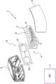
图1是根据本发明的指示而制造的汽车照明单元的实施例的示例的分解图;1 is an exploded view of an example of an embodiment of an automotive lighting unit manufactured in accordance with the teachings of the present invention;
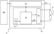
图2是图1所示的汽车照明单元的电子设备的实施例的示例的电路框图;FIG. 2 is a circuit block diagram of an example of an embodiment of the electronics of the automotive lighting unit shown in FIG. 1;
图3示出了OLED光源的等效电路模型;Figure 3 shows the equivalent circuit model of the OLED light source;
图4是示出在不存在故障状况的情况下响应于OLED光源的导频信号该OLED光源两端的电压的趋势的曲线图;4 is a graph showing the trend of the voltage across the OLED light source in response to a pilot signal of the OLED light source in the absence of a fault condition;
图5是示出在存在故障状况的情况下响应于OLED光源的导频信号该OLED光源两端的电压的趋势的曲线图;5 is a graph showing the trend of the voltage across the OLED light source in response to a pilot signal of the OLED light source in the presence of a fault condition;
图6是图1所示的汽车照明单元的电子设备的实施例的示例的电路图;6 is a circuit diagram of an example of an embodiment of the electronics of the automotive lighting unit shown in FIG. 1;
图7示出了故障状况下OLED光源的等效电路模型;Figure 7 shows an equivalent circuit model of an OLED light source under fault conditions;
图8示意性地示出了在不存在故障状况下处于接通状态的分段式OLED光源的一系列发光区域;Figure 8 schematically shows a series of light emitting regions of a segmented OLED light source in an on state in the absence of a fault condition;
图9示意性地示出了在左侧的四个黑色区域中存在故障状况的情况下图8所示的发光区域;Figure 9 schematically shows the light emitting area shown in Figure 8 in the presence of a fault condition in the four black areas on the left;
图10示意性地示出了在不存在故障状况下处于接通状态的多像素OLED光源的一系列发光区域;Figure 10 schematically illustrates a series of light emitting regions of a multi-pixel OLED light source in an on state in the absence of a fault condition;
图11示意性地示出了在以放大比例示出的黑色区域中存在故障状况的情况下图10所示的发光区域,该黑色区域表示像素大小的区域。FIG. 11 schematically shows the light-emitting area shown in FIG. 10 in the presence of a fault condition in the black area shown on an enlarged scale, which represents a pixel-sized area.
具体实施方式Detailed ways
现在将参照附图详细描述本发明,以允许本领域技术人员创建和使用本发明。对所描述的实施例的各种修改对于技术人员来说将是清楚的,并且在不脱离如所附权利要求书中所限定的本发明的保护范围的情况下,所描述的一般原理可以应用于其它实施例和应用。因此,本发明不应当被认为限于所描述和示出的实施例,而是应当被赋予与本文所描述和要求保护的原理和特征一致的最宽范围。The present invention will now be described in detail with reference to the accompanying drawings to allow those skilled in the art to make and use the invention. Various modifications to the described embodiments will be apparent to the skilled person, and the general principles described may be applied without departing from the scope of the invention as defined in the appended claims. for other embodiments and applications. Therefore, the present invention should not be considered limited to the embodiments described and illustrated, but should be accorded the widest scope consistent with the principles and features described and claimed herein.
参照图1,附图标记1整体上示意性地示出了根据本发明的实施例的示例制造的汽车照明单元的分解图。Referring to FIG. 1 , reference numeral 1 generally shows schematically an exploded view of an example manufactured automotive lighting unit in accordance with an embodiment of the present invention.
汽车照明单元1可优选地但非必须地包括成形后壳体2,该成形后壳体2优选地但非必须地为杯形。后壳体2可以例如被构造为使得其可以优选地但非必须地凹入到例如车辆车身(未示出)的隔区中。The automotive lighting unit 1 may preferably, but not necessarily, comprise a shaped rear housing 2, which is preferably, but not necessarily, cup-shaped. The rear shell 2 may for example be constructed such that it may preferably, but not necessarily, be recessed into a compartment such as a vehicle body (not shown).
根据图1所示的示例,汽车照明单元1可以进一步优选地包括前透镜体3,前透镜体3例如至少部分地由透明或半透明材料制成。前透镜体3可以构造为其可以耦接到后壳体2。前透镜体3可以优选地布置在后壳体2的开口处,使得前透镜体3优选地至少部分地从车辆的车身(未示出)露出。According to the example shown in FIG. 1 , the automotive lighting unit 1 may further preferably comprise a front lens body 3 , for example made at least partially of a transparent or translucent material. The front lens body 3 may be configured such that it can be coupled to the rear case 2 . The front lens body 3 may preferably be arranged at the opening of the rear housing 2 such that the front lens body 3 is preferably at least partially exposed from the body (not shown) of the vehicle.
根据图1所示的优选实施例,汽车照明单元1还包括照明设备4。According to the preferred embodiment shown in FIG. 1 , the automotive lighting unit 1 further comprises a
照明设备4可以包括OLED发光电路5。OLED发光电路5可以包括设置有一个或多个发光区域6的一个或多个OLED光源8(即,OLED)。The
根据图8和图9所示的可能实施例,发光区域6包括在至少一个OLED光源8中,即至少一个OLED,该至少一个OLED光源8具有所谓的“分段式”OLED发光模块。在图8和图9中示出的每个OLED段对应于OLED发光区域6。“分段式”OLED发光模块可以具有如下电路配置,该电路配置具有单个阴极(公共阴极)和多个独立的阳极,通过该多个独立阳极可以选择性地控制每个OLED段(即,整个OLED发光区域6)的完全且均匀的接通或关断状态。作为示例,在图9中,以黑色示出的四个OLED发光区域6处于下面详细描述的“死区状态”。应当注意,根据该实施例,OLED发光区域6,即OLED段,可以具有几十厘米量级的尺寸。According to a possible embodiment shown in FIGS. 8 and 9 , the light-emitting
根据图10和图11所示的不同实施例,OLED发光区域6包括在至少一个OLED光源8(即,至少一个OLED)中,该至少一个OLED光源8具有所谓的“多像素”OLED发光模块,其中,每个OLED发光区域6相对于(几毫米数量级的)传统OLED显示器中的“像素”的尺寸具有较小尺寸。作为示例,在图10中,以黑色示出的具有对应于一个像素的缩减尺寸的OLED发光区域6处于下面详细描述的“死区状态”。According to the different embodiments shown in Figures 10 and 11, the OLED light-emitting
应当理解,本发明不应当被认为限于以上所述并且在下面的讨论中将明确参考的“分段式”OLED发光模块和/或“多像素”OLED发光模块,而是可以被应用于任何类似的OLED发光模块,例如具有多个电气上独立的OLED的OLED模块,即包括它们各自的阳极和电极。It should be understood that the present invention should not be considered limited to the "segmented" OLED lighting modules and/or the "multi-pixel" OLED lighting modules described above and to which explicit reference is made in the discussion below, but may be applied to any similar An OLED light-emitting module, such as an OLED module having a plurality of electrically independent OLEDs, ie including their respective anodes and electrodes.
在故障状况下,OLED光源8的发光区域6可以在接通(ON)状态或关断(OFF)状态下操作,在接通(ON)状态下OLED光源8的OLED发光区域6响应于导频信号而发光,在关断(OFF)状态下在不存在导频信号的情况下,OLED光源8的OLED发光区域6不发光。Under fault conditions, the
在故障状况下,OLED光源8的发光区域6的状态可以对应于“死区状态”。在死区状态下,OLED光源8的OLED发光区域6保持关断,即,即使向其提供导频信号(阳极接收接通电压)时,其也不发光。In a fault condition, the state of the
为了增加本发明的清楚性和对本发明的理解,图8示出例如“分段式”OLED光源8,其中,六个相应的发光区域6以灰色示出以指示接通状态,而图9示出相同的OLED光源8,其中,四个发光区域6以黑色示出以指示死区状态。In order to increase the clarity and understanding of the present invention, Figure 8 shows, for example, a "segmented" OLED
为了增加本发明的清楚性和对本发明的理解,图10替代地示出了“多像素”OLED光源8的示例,其中,所有发光区域6以灰色示出以指示接通状态,而图11示出了相同的OLED光源8,其中一个发光区域6以黑色示出以指示死区状态。To increase the clarity and understanding of the present invention, Figure 10 instead shows an example of a "multi-pixel" OLED
照明设备4还可以包括电子设备12,电子设备12用于控制一个或多个OLED光源8,选择性地在接通状态和关断状态之间切换该一个或多个OLED光源8。The
根据本发明,电子设备12进一步用于当其检测到在OLED光源8的一个或多个发光区域6中存在死区状态时确定照明设备4的故障状况。According to the invention, the
根据图2所示的可能实施例,电子设备12可以包括例如电子控制电路14和电子诊断电路10,电子控制电路14被设计为选择性地控制OLED光源8,电子诊断电路10被设计为检测/确定OLED光源8的发光区域6的上述故障状况。According to a possible embodiment shown in FIG. 2 , the
优选地,但不是必须地,如图1中的示例所示,电子设备12的控制电路14和电子诊断电路10可以都布置在单个公共PCB中。然而,应当理解,电子设备12的控制电路14和电子诊断电路10可以布置在单独的相应电子PCB板中,或者布置在安装有OLED发光电路5的同一电子板中。Preferably, but not necessarily, the
根据图1所示的优选实施例的示例,OLED发光电路5可以方便地设置在汽车照明单元1中,使得该OLED发光电路5直接或间接面向前透镜体3,以在车辆(未示出)的外部执行照明功能和/或任何车辆光信号发送功能。According to the example of the preferred embodiment shown in FIG. 1 , the OLED light-emitting
应理解,在以下描述中,术语“汽车照明单元”应理解如下:前灯、后灯、至少一个外部标记/位置灯、至少一个方向指示灯(通常用箭头指示)、至少一个制动灯/刹车灯(通常用停止指示)、至少一个雾灯、至少一个倒车灯、至少一个近光灯、至少一个远光灯或可安装在类似机动车辆(优选是机动车辆)中的任何其它类型的灯。It is to be understood that in the following description, the term "automotive lighting unit" is to be understood as follows: front light, rear light, at least one exterior marker/position light, at least one direction indicator (usually indicated by an arrow), at least one brake light/ Brake lights (usually with a stop indicator), at least one fog light, at least one reversing light, at least one low beam, at least one high beam or any other type that can be installed in a similar motor vehicle (preferably a motor vehicle) lamp.
根据图1所示的优选实施例,照明设备4可以优选地但不是必须地容纳在汽车照明单元1内,例如容纳在后壳体2内。According to the preferred embodiment shown in FIG. 1 , the
然而,应当理解,本发明不限于将电子照明设备4设置在汽车照明单元1内。特别地,电子照明设备4可以设置在车辆的其它部分中和/或集成到车辆的其它部分中。例如,电子照明设备4可以设置在后窗上和/或设置在车辆的车身/底盘中/上。However, it should be understood that the present invention is not limited to arranging the
根据图1所示的优选实施例,OLED发光电路5的OLED光源8可以通过电子控制电路14基于由安装在车辆中的中央控制单元100(例如电子控制单元)提供的一个或多个控制信号来控制,以选择性地能够切换成接通(ON)状态和关断(OFF)状态。应当理解,中央控制单元100可以包括在汽车照明单元1中。According to the preferred embodiment shown in FIG. 1 , the
根据图2所示的优选实施例,电子控制电路14可以用于从电子诊断电路10接收信号,该信号指示由于在OLED光源8的一个或多个发光区域6中存在死区状态而导致的故障状况。According to the preferred embodiment shown in FIG. 2 , the
电子控制电路14还可以用于与中央控制单元100通信,以向其提供至少指示故障状况的信号,该故障状况指示OLED光源8的一个或多个发光区域6中的死区状态。The
电子控制电路14可以经由至少一个通信总线(未示出)连接到中央控制单元100以接收控制信号,并且可以进而设置有控制端子以提供导频信号,从而选择性地控制一个或多个OLED光源8。由电子控制电路14生成的导频信号可以使OLED光源8切换成接通(ON)状态或关断(OFF)状态。应当理解,由电子控制电路14提供的导频信号还可以引起对OLED光源8的控制电学量(例如电流或电压)的调节,以便确定OLED光源8的一个或多个照明参数(例如光强度和/或颜色)的相应调制和/或改变。
应当理解,电子设备12的其他实施例也是可能的。例如,电子设备12可以包括静态配置寄存器(未示出),其包含指示要施加到OLED源8的电流值的预定义控制/命令配置。该寄存器进而可以包含在存储器中,该存储器安装在容纳控制电路14的同一电子板(未示出)中。It should be understood that other embodiments of the
关于电子诊断电路10,其可以用于与电子控制电路14和/或中央控制单元100单向和/或双向通信。中央控制单元100可以用于基于指示由电子设备12检测到的OLED光源8的故障状况的一个或多个数据/电信号来提供上述控制信号。With regard to the electronic
根据图2、图4和图5所示的优选实施例的示例,电子设备12可以以如下方式配置:通过在高电平值和低电平值之间转变/变化的导频信号P1来控制至少一个OLED光源8;确定指示在导频信号在高电平值和低电平值之间变化/转变之后的测量时间间隔toff中OLED光源8的电气行为的电学量;以及基于在测量时间间隔toff期间测量的电学量来确定OLED光源8的故障状况。According to the example of the preferred embodiment shown in Figures 2, 4 and 5, the
优选地,电子设备12可以用于经由导频信号P1来控制OLED光源8,该导频信号P1对应于图4和图5所示的方形或矩形波形电压信号。电压信号波形可以具有与上述低电平值相对应的最小电压Vmin、与上述高电平值相对应的最大电压Vmax、导频信号P1从最小电压Vmin变为最大电压Vmax的前沿F1和导频信号P1从最大电压Vmax变为最小电压Vmin的后沿F2。Preferably, the
优选地,电子设备12可以用于在紧接在导频信号P1的后沿F2之后的测量时间间隔toff期间测量和/或确定对应于OLED光源8的电压VS的电学量,并且基于测量/确定的电压VS来确定与OLED光源8的至少一个发光区域6中的死区状态相关联的故障状况。Preferably, the
电压Vmax优选地对应于用于在OLED光源8转变成接通状态期间对OLED的等效电路的电容器(下面描述)充电的电压值。The voltage Vmax preferably corresponds to the voltage value used to charge the capacitor (described below) of the equivalent circuit of the OLED during the transition of the OLED
优选地,电压Vmin可以对应于用于至少部分地使OLED的等效电路的电容器放电的电压值。Preferably, the voltage Vmin may correspond to a voltage value for at least partially discharging the capacitor of the equivalent circuit of the OLED.
优选地,可以经由阳极将导频信号P1提供给OLED光源8,以将OLED光源8的相关发光区域6转换成接通状态。Preferably, the pilot signal P1 may be provided to the OLED
具有近似矩形波形状的特别方便的导频信号P1可以是例如PWM(脉宽调制)信号,其将在下面的部分中明确地提及,而不会因此失去任何一般性。A particularly convenient pilot signal P1 having an approximately rectangular wave shape may be, for example, a PWM (pulse width modulation) signal, which will be explicitly mentioned in the following sections without any loss of generality thereby.
参照图4和图5,PWM类型的导频信号P1优选地包括正脉冲,该正脉冲在相应的时间间隔ton期间具有最大电压Vmax并且在相应的测量时间间隔toff期间具有最小电压Vmin。4 and 5, the PWM type pilot signal P1 preferably comprises a positive pulse having a maximum voltage Vmax during the respective time interval ton and a minimum voltage Vmin during the respective measurement time interval toff.
在测量时间间隔toff期间,PWM类型的导频信号P1的最小电压Vmin可以优选地大约为零(Vmin大约等于0伏特)。During the measurement time interval toff, the minimum voltage Vmin of the PWM-type pilot signal P1 may preferably be approximately zero (Vmin approximately equals 0 volts).
申请人已经发现,在测量时间间隔toff期间测量的电压VS具有取决于OLED光源8的等效电路的电容器的瞬态放电的变化,并且指示存在或不存在OLED光源8的故障状况。The applicant has found that the voltage VS measured during the measurement time interval toff has a variation depending on the transient discharge of the capacitors of the equivalent circuit of the OLED
实际上,在测量时间间隔toff期间测量的电压VS取决于OLED光源8的故障/破损的存在。Indeed, the voltage VS measured during the measurement time interval toff depends on the presence of a malfunction/breakage of the OLED
更详细地,在测量时间间隔toff期间测量的电压VS基于在OLED光源8的一个或多个发光区域6中存在/不存在死区状态而变化。In more detail, the voltage VS measured during the measurement time interval toff varies based on the presence/absence of a dead zone state in one or more
为了增加对于本发明的理解并因此增加本发明的清楚性,参考图3中所示的OLED光源8的等效电路模型。In order to increase the understanding and therefore clarity of the invention, reference is made to the equivalent circuit model of the OLED
该模型包括:The model includes:
电阻器,其连接在阳极端子A和节点N之间,该电阻器具有指示相关OLED电极的电阻的电阻Re;a resistor connected between the anode terminal A and the node N, the resistor having a resistance Re indicative of the resistance of the associated OLED electrode;
第一电气分支,其连接在节点A和阴极端子C之间,沿着该第一电气分支串联连接有理想二极管D1、具有内建电阻Rbi的电阻器和表示OLED光源8的内建电压的电压发生器Vbi;A first electrical branch, connected between node A and cathode terminal C, along which ideal diode D1 , a resistor with built-in resistance Rbi and a voltage representing the built-in voltage of OLED
第二电气分支,其连接在节点N和阴极端子C之间,沿着该第二电气分支串联连接有理想二极管D2、具有电阻Rs的电阻器和表示OLED光源8具有实质/显著的电流传导所需的阈值电压的电压发生器Vo;A second electrical branch, which is connected between node N and cathode terminal C, along which is connected in series an ideal diode D2, a resistor with resistance Rs, and the means by which the OLED
理想二极管D3,其连接在两个理想二极管D1和D2的阳极之间;ideal diode D3, which is connected between the anodes of the two ideal diodes D1 and D2;
电容器,其与电阻为Rbi的电阻器并联连接并且具有扩散电容Cd,扩散电容Cd表示OLED电容取决于阴极的材料、电压和频率;a capacitor, which is connected in parallel with a resistor of resistance Rbi and has a diffusion capacitance Cd, which means that the OLED capacitance depends on the material, voltage and frequency of the cathode;
电容器,其具有与OLED的形状因子相关联的几何电容Cg;以及a capacitor having a geometric capacitance Cg associated with the form factor of the OLED; and
电阻器,该电阻器具有泄漏电阻Rp,与几何电容电容器Cg并联连接,并且泄漏电流Ip流过该电阻器。A resistor, which has a leakage resistance Rp, is connected in parallel with the geometric capacitance capacitor Cg and through which the leakage current Ip flows.
申请人进行的实验室测试已经表明,响应于PWM信号脉冲的上升沿,OLED光源8两端的电压表现出从最小电压Vmin到最大电压Vmax的快速转变。转变的速度基本上取决于对OLED光源8的等效电路的上述电容器的充电快速发生的事实。Laboratory tests carried out by the applicant have shown that, in response to the rising edge of the PWM signal pulse, the voltage across the OLED
测试还表明,在导频信号P1的脉冲或方波的下降沿之后,存在OLED光源8两端的电压VS从最大电压Vmax到中间电压的缓慢转变。在这种情况下,电压VS的变化的缓慢度基本上取决于OLED光源8的等效电路的电容器的瞬态放电。Tests have also shown that after the falling edge of the pulse or square wave of the pilot signal P1, there is a slow transition of the voltage VS across the OLED
申请人还发现,当OLED光源8的一个或多个发光区域6处于“死区状态”时,发生变化,特别是与在没有死区状态的情况下在相同的测量时间间隔toff中测量的中间电压相比,在测量时间间隔toff期间的中间电压减小。The applicant has also found that changes occur when one or more light-emitting
换句话说,申请人已经发现,在紧接提供给与OLED光源8的发光区域6相关联的阳极的导频信号P1的脉冲或方波/矩形波的后沿之后的测量时间间隔toff中测量的电压VS,使得能够检测由发光区域6中的至少一个发光区域中的死区状态的存在而引起的OLED光源8的故障状况的存在。In other words, the Applicant has found that the measurement is performed in the measurement time interval toff immediately after the trailing edge of the pulse or square/rectangular wave of the pilot signal P1 supplied to the anode associated with the
图7示出了在由存在死区状态而引起的故障状况下的OLED光源8的等效电路模型。应当注意,OLED光源8的死区状态可能由OLED光源8的阴极的损坏引起。这种对阴极的损坏会导致OLED光源8的阳极和阴极之间的短路。特别地,当OLED受到过电压(例如,静电放电)时和/或当OLED在其操作期间暴露于接近-40℃的低温时,会引起这种损坏。Figure 7 shows an equivalent circuit model of the OLED
OLED光源8的故障状况在图7中的等效模型中示出,该等效模型包括与泄漏电阻Rp并联连接的理论故障电阻Rdp。理论故障电阻Rdp具有极低值,基本上为零,并且限定了在上述故障状况下发生的阳极和阴极之间的短路状况。The failure condition of the OLED
图4示出了在OLED光源8的正确操作的条件下响应于导频信号P1测量的电压VS的时间趋势的曲线图的示例,其中电压VS大于中间电压Vint。FIG. 4 shows an example of a graph of the time trend of the voltage VS measured in response to the pilot signal P1 under conditions of correct operation of the OLED
图5示出了在OLED光源8的发光区域6中的死区状态引起的故障状况下响应于导频信号P1测量的电压VS的时间趋势的曲线图的示例,其中电压VS低于中间电压Vint。FIG. 5 shows an example of a graph of the time trend of the voltage VS measured in response to the pilot signal P1 under fault conditions caused by dead zone states in the
参考图2所示的实施例的可能示例,电子诊断电路10可以包括:电子测量设备16,其被设计为在测量时间间隔toff期间测量OLED光源8的电压VS;优选地但不是必须地,存储器设备18,其被设计为存储指示不存在OLED光源8的故障状况的至少一个参考电压阈值,例如电压Vint;以及电子处理设备19,其基于电压VS和参考电压阈值Vint来确定故障状况。OLED源8的故障状况指示在一个或多个OLED发光区域6中存在死区状态,并且可以在电压VS不满足具有电压阈值Vint的预定义条件时确定。With reference to a possible example of the embodiment shown in FIG. 2 , the electronic
当电压VS低于电压阈值Vint时,可以确定指示在一个或多个OLED发光区域6中存在死区状态的OLED光源8的故障状况。When the voltage VS is below the voltage threshold Vint, a fault condition of the OLED
应当理解,电子设备12可以借助于预定义诊断功能而不是借助于电压VS和参考电压阈值Vint之间的比较/交叉检验,来确定在一个或多个OLED发光区域6中存在死区状态。It should be understood that the
例如,根据不同的实施例,电子设备12可以以如下方式配置:在测量时间间隔(toff)期间进行多个电压测量VS(t);基于测量的电压VS(t)确定/构建在测量时间间隔toff期间的电压曲线;确定在测量时间间隔toff期间测量的电压曲线与指示在一个或多个OLED发光区域6中不存在死区状态的情况下的电压趋势的参考电压曲线之间的均方误差。For example, according to various embodiments, the
电子设备12可以用于基于该均方误差,例如当均方误差超过预定误差阈值时,确定指示一个或多个OLED发光区域6中的死区状态的故障状况的存在。The
根据不同的实施例,电子设备12以如下方式配置:通过ys=as*e(-bsx)+cs类型的指数函数ys来表征(数学地表示)测量时间间隔toff期间电压VS(t)的趋势;将表征指数函数ys的系数as、bs和cs与参考指数函数yr=a1*e-b1x+c1的预定系数a1、b1和c1进行比较,该参考指数函数yr=a1*e-b1x+c1表征在不存在指示死区状态的故障状况的情况下电压Vs的趋势;并且基于系数as、bs和cs与系数a1、b1和c1之间的比较结果来确定在一个或多个OLED发光区域6中死区状态的存在。According to a different embodiment, the
根据不同的实施例,电子设备12可以以如下方式配置:借助于积分函数/运算来计算指示在测量时间间隔toff期间电压VS的变化的曲线下方的面积的值;将所计算的值与预定值进行比较,并且基于比较的结果来确定指示一个或多个OLED发光区域6中的死区状态的故障状况的存在。According to different embodiments, the
申请人事实上已经发现,在存在指示死区状态的故障状况的情况下,测量时间间隔toff期间的电压曲线VS所对向的面积小于与不存在指示死区状态的故障状况的情况相关联的测量时间间隔toff期间的电压曲线所对向的面积。The applicant has in fact found that, in the presence of a fault condition indicative of a deadband state, the area subtended by the voltage curve VS during the measurement time interval toff is smaller than the area associated with the absence of a fault condition indicative of a deadband state The area subtended by the voltage curve during the time interval toff is measured.
图6示出了电子设备12的可能实施例,其中,电子控制电路14包括控制级20,诊断电路10包括减法级21、积分级22和比较级23。FIG. 6 shows a possible embodiment of the
控制级20被设计为借助于与PWM信号相对应的导频信号P1来控制OLED光源8。控制级20可以包括:用于OLED光源8的控制支路,其设置有串联连接在OLED光源8的第一端子和置于参考电压(例如接地电压)下的端子之间的电子开关(例如晶体管B1)和电阻器B2;发生器24,其输出导频信号P1(电压或电流中的PWM),该导频信号P1的特征在于时间间隔ton期间的脉冲,并且在测量时间间隔toff期间不存在脉冲;运算放大器A1,其设置有接收导频信号P1的非反相端子、连接在电阻器B2和晶体管B1之间的反相端子、以及与晶体管的控制端子连接的输出端子。The control stage 20 is designed to control the OLED
诊断电路10的减法级21连接在OLED光源8的第一端子和OLED光源8的第二端子之间,OLED光源8的第二端子又连接到电源电压Vcc。诊断电路10的减法级21用于响应于导频信号P1,提供在测量时间间隔toff期间在OLED光源8两端测量的输出电压VS。The
诊断电路10的积分级22连接在减法级21的输出处,并且用于接收测量电压VS并且在测量时间间隔toff上对其进行积分,以便确定和输出指示OLED光源8在测量时间间隔toff期间的电气行为的值。The
诊断电路的比较级23与积分级22的输出进行连接,以接收指示OLED光源8在测量时间间隔toff期间的电气行为的值,并且用于将该值与预定阈值进行比较,并且基于比较的结果提供输出信号,该输出信号指示由于在OLED光源8的一个或多个OLED发光区域6中存在或不存在死区状态而导致存在或不存在故障状况。The comparison stage 23 of the diagnostic circuit is connected to the output of the
例如,比较级23可以输出指示故障状况的存在的方波信号,该故障状况指示在OLED光源8的一个或多个OLED发光区域6中的死区状态,或者输出指示不存在故障状况(即,不存在死区状态)的等于零的信号。For example, comparator stage 23 may output a square wave signal indicative of the presence of a fault condition indicating a deadband condition in one or more OLED
优选地,PWM类型的导频信号P1可以具有在大约100赫兹和大约500赫兹之间的频率。申请人还发现,PWM导频信号P1的优选频率可以是大约200赫兹。Preferably, the PWM type pilot signal P1 may have a frequency between about 100 Hz and about 500 Hz. Applicants have also found that the preferred frequency of the PWM pilot signal P1 may be about 200 Hz.
申请人事实上已经发现,使用具有上述频率的PWM导频信号P1允许当OLED光源8处于接通状态时诊断故障状况,而不显著改变照明单元对于观察者的眼睛的发光状态。The applicant has in fact found that using a PWM pilot signal P1 with the above-mentioned frequency allows to diagnose fault conditions when the OLED
应当理解,上述电子设备12可以在照明单元1的任何其它操作阶段期间确定OLED源8的故障状况。It will be appreciated that the aforementioned
例如,根据可能的实施例,上述电子设备12可以在关断OLED光源8的步骤期间确定OLED光源的故障状况。在这种情况下,电子诊断电路10可以基于导频信号P1的波的后沿来确定电压VS,随后照明单元被关断。For example, according to a possible embodiment, the aforementioned
如上所述,电子诊断电路10因此可以方便地将信息传送到电子控制电路14和/或中央控制单元100,该消息指示由在OLED光源8的至少一个OLED发光区域6中存在死区状态引起的OLED光源8的故障状况。As mentioned above, the electronic
电子控制电路14和/或中央控制单元100可以用于基于由电子诊断电路10提供的信息来执行控制操作。
控制操作可以包括:当检测到OLED光源8的故障状况时关断OLED光源8;和/或向用户提供指示照明单元的故障状况的信息(警告);和/或向用户提供指示经受诊断的OLED光源8的故障状况的信息。The control operation may include: turning off the OLED
上述照明单元的益处如下。The benefits of the above lighting unit are as follows.
该方法使得可以通过简单且因此实施起来经济的解决方案来检测OLED光源的故障状况。This method makes it possible to detect faulty conditions of OLED light sources by means of a simple and therefore economical solution to implement.
由于OLED发光区域中的死区状态的检测,可以及时地确定可能不符合规定的由照明单元发射的光的显著光度变化。事实上,在OLED发光区域中存在死区状态的情况下,照明单元的电流吸收增加,这同时导致来自照明单元的光显著减少。Due to the detection of dead zone states in the light emitting area of the OLED, significant photometric changes in the light emitted by the lighting unit that may not be in compliance can be determined in time. In fact, in the presence of dead zone states in the OLED light-emitting area, the current absorption of the lighting unit increases, which at the same time results in a significant reduction in light from the lighting unit.
最后,清楚的是,在不脱离本发明的范围的情况下,可以对上述汽车照明单元、电子照明设备和操作方法进行修改和变化。Finally, it is clear that modifications and variations may be made to the automotive lighting unit, electronic lighting device and method of operation described above without departing from the scope of the present invention.
Claims (15)
Translated fromChineseApplications Claiming Priority (2)
| Application Number | Priority Date | Filing Date | Title |
|---|---|---|---|
| EP19166378.0 | 2019-03-29 | ||
| EP19166378.0AEP3715885B1 (en) | 2019-03-29 | 2019-03-29 | Automobile lighting unit with oled light sources and related operating method |
Publications (2)
| Publication Number | Publication Date |
|---|---|
| CN111757572Atrue CN111757572A (en) | 2020-10-09 |
| CN111757572B CN111757572B (en) | 2024-11-19 |
Family
ID=66668664
Family Applications (1)
| Application Number | Title | Priority Date | Filing Date |
|---|---|---|---|
| CN202010232075.8AActiveCN111757572B (en) | 2019-03-29 | 2020-03-27 | Automotive lighting unit with OLED light source and related operating method |
Country Status (5)
| Country | Link |
|---|---|
| US (1) | US11650243B2 (en) |
| EP (1) | EP3715885B1 (en) |
| JP (1) | JP7584903B2 (en) |
| KR (1) | KR102753325B1 (en) |
| CN (1) | CN111757572B (en) |
Citations (15)
| Publication number | Priority date | Publication date | Assignee | Title |
|---|---|---|---|---|
| US5194889A (en)* | 1991-02-07 | 1993-03-16 | Asahi Kogaku Kogyo Kabushiki Kaisha | Flashing device |
| KR20060113000A (en)* | 2005-04-28 | 2006-11-02 | 삼성에스디아이 주식회사 | Defective Method of LED Display |
| US20090322800A1 (en)* | 2008-06-25 | 2009-12-31 | Dolby Laboratories Licensing Corporation | Method and apparatus in various embodiments for hdr implementation in display devices |
| CN101662867A (en)* | 2008-08-29 | 2010-03-03 | 株式会社小糸制作所 | Dimming control system for vehicular lamp |
| US20130050288A1 (en)* | 2011-08-30 | 2013-02-28 | Magnachip Semiconductor, Ltd. | Led driver apparatus |
| CN103428956A (en)* | 2012-05-17 | 2013-12-04 | 东芝照明技术株式会社 | Power supply device and luminaire |
| CN104284479A (en)* | 2013-07-10 | 2015-01-14 | 松下电器产业株式会社 | Light-emitting diode driving device, vehicle lighting equipment and vehicle including the device |
| CN104395668A (en)* | 2012-05-04 | 2015-03-04 | 丽托尼克斯有限公司 | Lighting device |
| JP2016162598A (en)* | 2015-03-02 | 2016-09-05 | パナソニックIpマネジメント株式会社 | Lighting device, headlight device, and vehicle |
| AU2015263835A1 (en)* | 2014-05-22 | 2017-01-05 | Ozuno Holdings Pty Ltd | A zero-crossing detection circuit for a dimmer circuit |
| US20170048935A1 (en)* | 2015-08-12 | 2017-02-16 | Samsung Electronics Co., Ltd. | Light emitting diode (led) driving apparatus, lighting apparatus, and current control circuit |
| US9603210B1 (en)* | 2014-12-24 | 2017-03-21 | Sandia Corporation | High speed, high current pulsed driver circuit |
| FR3049064A1 (en)* | 2016-03-21 | 2017-09-22 | Valeo Vision | METHOD AND DEVICE FOR DETECTING RESISITIVE SHORT CIRCUITS IN A LUMINOUS DEVICE FOR A MOTOR VEHICLE |
| US20180213617A1 (en)* | 2014-08-26 | 2018-07-26 | Osram Oled Gmbh | Method for operating an optoelectronic assembly and optoelectronic assembly |
| CN109237413A (en)* | 2017-06-17 | 2019-01-18 | 深圳市绎立锐光科技开发有限公司 | a car light system |
Family Cites Families (4)
| Publication number | Priority date | Publication date | Assignee | Title |
|---|---|---|---|---|
| WO2008154736A1 (en) | 2007-06-18 | 2008-12-24 | Leddartech Inc. | Lighting system with driver assistance capabilities |
| JP5900980B2 (en)* | 2011-07-04 | 2016-04-06 | Necライティング株式会社 | Light emitting device failure detector and light emitting device failure detection method |
| JP2014150040A (en) | 2013-02-04 | 2014-08-21 | Koito Mfg Co Ltd | Lighting fixture for vehicle |
| JP6066829B2 (en) | 2013-05-23 | 2017-01-25 | 三菱電機株式会社 | LED lighting device and in-vehicle lamp |
- 2019
- 2019-03-29EPEP19166378.0Apatent/EP3715885B1/enactiveActive
- 2020
- 2020-03-27USUS16/832,070patent/US11650243B2/enactiveActive
- 2020-03-27KRKR1020200037419Apatent/KR102753325B1/enactiveActive
- 2020-03-27JPJP2020058806Apatent/JP7584903B2/enactiveActive
- 2020-03-27CNCN202010232075.8Apatent/CN111757572B/enactiveActive
Patent Citations (15)
| Publication number | Priority date | Publication date | Assignee | Title |
|---|---|---|---|---|
| US5194889A (en)* | 1991-02-07 | 1993-03-16 | Asahi Kogaku Kogyo Kabushiki Kaisha | Flashing device |
| KR20060113000A (en)* | 2005-04-28 | 2006-11-02 | 삼성에스디아이 주식회사 | Defective Method of LED Display |
| US20090322800A1 (en)* | 2008-06-25 | 2009-12-31 | Dolby Laboratories Licensing Corporation | Method and apparatus in various embodiments for hdr implementation in display devices |
| CN101662867A (en)* | 2008-08-29 | 2010-03-03 | 株式会社小糸制作所 | Dimming control system for vehicular lamp |
| US20130050288A1 (en)* | 2011-08-30 | 2013-02-28 | Magnachip Semiconductor, Ltd. | Led driver apparatus |
| CN104395668A (en)* | 2012-05-04 | 2015-03-04 | 丽托尼克斯有限公司 | Lighting device |
| CN103428956A (en)* | 2012-05-17 | 2013-12-04 | 东芝照明技术株式会社 | Power supply device and luminaire |
| CN104284479A (en)* | 2013-07-10 | 2015-01-14 | 松下电器产业株式会社 | Light-emitting diode driving device, vehicle lighting equipment and vehicle including the device |
| AU2015263835A1 (en)* | 2014-05-22 | 2017-01-05 | Ozuno Holdings Pty Ltd | A zero-crossing detection circuit for a dimmer circuit |
| US20180213617A1 (en)* | 2014-08-26 | 2018-07-26 | Osram Oled Gmbh | Method for operating an optoelectronic assembly and optoelectronic assembly |
| US9603210B1 (en)* | 2014-12-24 | 2017-03-21 | Sandia Corporation | High speed, high current pulsed driver circuit |
| JP2016162598A (en)* | 2015-03-02 | 2016-09-05 | パナソニックIpマネジメント株式会社 | Lighting device, headlight device, and vehicle |
| US20170048935A1 (en)* | 2015-08-12 | 2017-02-16 | Samsung Electronics Co., Ltd. | Light emitting diode (led) driving apparatus, lighting apparatus, and current control circuit |
| FR3049064A1 (en)* | 2016-03-21 | 2017-09-22 | Valeo Vision | METHOD AND DEVICE FOR DETECTING RESISITIVE SHORT CIRCUITS IN A LUMINOUS DEVICE FOR A MOTOR VEHICLE |
| CN109237413A (en)* | 2017-06-17 | 2019-01-18 | 深圳市绎立锐光科技开发有限公司 | a car light system |
Non-Patent Citations (3)
| Title |
|---|
| R. H. KAUFMANN: "Short-Circuit Calculating Procedure for Low-Voltage A-C Systems", 《TRANSACTIONS OF THE AMERICAN INSTITUTE OF ELECTRICAL ENGINEERS》, vol. 60, no. 12* |
| 王华鸣: "高功率LED照明灯具应用及相关问题的思考", 《.视听界(广播电视技术)》* |
| 陈英, 杨瑜: "基于高边电流检测驱动LED", 《2011年西南三省一市自动化与仪器仪表学术年会论文集》* |
Also Published As
| Publication number | Publication date |
|---|---|
| US11650243B2 (en) | 2023-05-16 |
| JP7584903B2 (en) | 2024-11-18 |
| JP2020167161A (en) | 2020-10-08 |
| US20200309844A1 (en) | 2020-10-01 |
| CN111757572B (en) | 2024-11-19 |
| KR102753325B1 (en) | 2025-01-10 |
| EP3715885A1 (en) | 2020-09-30 |
| EP3715885B1 (en) | 2025-05-28 |
| KR20200116061A (en) | 2020-10-08 |
Similar Documents
| Publication | Publication Date | Title |
|---|---|---|
| KR102534526B1 (en) | Device and method for detecting a short-circuited light-emitting diode in a light device of a motor vehicle | |
| JP5900980B2 (en) | Light emitting device failure detector and light emitting device failure detection method | |
| JP6153023B2 (en) | LIGHT EMITTING ELEMENT LIGHTING DEVICE, LIGHT EMITTING MODULE, LIGHTING DEVICE, AND LIGHT EMITTING ELEMENT LIGHTING METHOD | |
| JP2011171547A (en) | Fault detection circuit of light emitting diode | |
| CN111751081B (en) | Automotive lighting unit with OLED light source and related operating method | |
| CN112449466B (en) | Linear LED driving circuit, power switch detection method and dimming control method | |
| CN111757572B (en) | Automotive lighting unit with OLED light source and related operating method | |
| CN103926500A (en) | Method for detecting LED constant current driving circuit performance | |
| US3925771A (en) | Voltage checking means for an electric circuit employing two power sources | |
| KR101903970B1 (en) | Tell-Tale Circuit of LED Lamp in Vehicle | |
| JP2007249520A (en) | Fire sensor | |
| EP3729016B1 (en) | Battery electrolyte level monitor, system, and method | |
| NZ762353B2 (en) | Battery electrolyte level monitor, system, and method | |
| CN120294456A (en) | Vehicle lamp derating method, device, vehicle, medium and program product | |
| CN108575021A (en) | Dynamic steering circuit based on TLD2314EL | |
| JPH0574502A (en) | Apparatus for detecting condition of storage battery | |
| JPS62105377A (en) | Monitoring device for charging state of car-battery | |
| HK40017897A (en) | Battery electrolyte level monitor, system, and method |
Legal Events
| Date | Code | Title | Description |
|---|---|---|---|
| PB01 | Publication | ||
| PB01 | Publication | ||
| SE01 | Entry into force of request for substantive examination | ||
| SE01 | Entry into force of request for substantive examination | ||
| GR01 | Patent grant | ||
| GR01 | Patent grant |