CN111751275A - A sliding push-out test device and method for the bond performance between section steel and restrained concrete - Google Patents
A sliding push-out test device and method for the bond performance between section steel and restrained concreteDownload PDFInfo
- Publication number
- CN111751275A CN111751275ACN202010743783.8ACN202010743783ACN111751275ACN 111751275 ACN111751275 ACN 111751275ACN 202010743783 ACN202010743783 ACN 202010743783ACN 111751275 ACN111751275 ACN 111751275A
- Authority
- CN
- China
- Prior art keywords
- load
- section steel
- plate
- steel
- strain
- Prior art date
- Legal status (The legal status is an assumption and is not a legal conclusion. Google has not performed a legal analysis and makes no representation as to the accuracy of the status listed.)
- Pending
Links
- 229910000831SteelInorganic materials0.000titleclaimsabstractdescription75
- 239000010959steelSubstances0.000titleclaimsabstractdescription75
- 238000012360testing methodMethods0.000titleclaimsabstractdescription61
- 238000000034methodMethods0.000titleabstractdescription10
- 238000006073displacement reactionMethods0.000claimsabstractdescription26
- 238000006243chemical reactionMethods0.000claimsdescription12
- 238000009662stress testingMethods0.000claimsdescription6
- 230000008054signal transmissionEffects0.000claimsdescription3
- 238000004519manufacturing processMethods0.000claimsdescription2
- 238000010998test methodMethods0.000claims1
- 238000009434installationMethods0.000description11
- 238000010586diagramMethods0.000description6
- 230000006835compressionEffects0.000description5
- 238000007906compressionMethods0.000description5
- 230000000452restraining effectEffects0.000description2
- 239000000853adhesiveSubstances0.000description1
- 230000001070adhesive effectEffects0.000description1
- 238000005452bendingMethods0.000description1
- 230000009286beneficial effectEffects0.000description1
- 239000002131composite materialSubstances0.000description1
- 230000037029cross reactionEffects0.000description1
- 238000012986modificationMethods0.000description1
- 230000004048modificationEffects0.000description1
Images


Classifications
- G—PHYSICS
- G01—MEASURING; TESTING
- G01N—INVESTIGATING OR ANALYSING MATERIALS BY DETERMINING THEIR CHEMICAL OR PHYSICAL PROPERTIES
- G01N19/00—Investigating materials by mechanical methods
- G01N19/04—Measuring adhesive force between materials, e.g. of sealing tape, of coating
Landscapes
- Physics & Mathematics (AREA)
- Health & Medical Sciences (AREA)
- Life Sciences & Earth Sciences (AREA)
- Chemical & Material Sciences (AREA)
- Analytical Chemistry (AREA)
- Biochemistry (AREA)
- General Health & Medical Sciences (AREA)
- General Physics & Mathematics (AREA)
- Immunology (AREA)
- Pathology (AREA)
- Investigating Strength Of Materials By Application Of Mechanical Stress (AREA)
Abstract
Description
Translated fromChinese技术领域technical field
本发明属于建筑结构试验领域,具体涉及一种型钢与约束混凝土粘结性能滑移推出试验装置及方法。The invention belongs to the field of building structure testing, and in particular relates to a sliding push-out test device and method for the bonding performance of section steel and restrained concrete.
背景技术Background technique
钢管约束型钢混凝土柱和FRP约束型钢混凝土柱具有承载力高、刚度大和抗震性能好等优势,作为新型组合构件受到了学术和工程界的广泛关注。其中,型钢与约束混凝土间的粘结性能是这类新型组合构件能够良好工作的基础。目前,针对型钢与混凝土的粘结性能主要采用推出试验进行测试。现有推出试验装置和方法无法使混凝土处于约束下的三轴受压状态,只能测试型钢与非约束混凝土的粘结性能,不能准确获取钢管或FRP约束型钢混凝土柱中型钢与约束混凝土间的粘结性能。Steel-contained steel-concrete columns and FRP-confined steel-concrete columns have the advantages of high bearing capacity, high stiffness and good seismic performance. Among them, the bonding performance between profile steel and restrained concrete is the basis for this new type of composite member to work well. At present, the bonding performance of steel and concrete is mainly tested by push-out test. The existing push-out test devices and methods cannot make the concrete in a constrained triaxial compression state, and can only test the bonding performance between the section steel and the unconstrained concrete, and cannot accurately obtain the relationship between the section steel and the constrained concrete in the steel tube or the FRP constrained section steel concrete column. Bonding properties.
目前对于型钢与约束混凝土粘结性能的推出试验未见相关文献报道,实验室也没有能准确获取二者粘结性能的相关试验加载装置。At present, there is no relevant literature report on the push-out test of the bonding performance between profile steel and restrained concrete, and there is no relevant test loading device that can accurately obtain the bonding performance of the two in the laboratory.
发明内容SUMMARY OF THE INVENTION
本部分的目的在于概述本发明的实施例的一些方面以及简要介绍一些较佳实施例。在本部分以及本申请的说明书摘要和发明名称中可能会做些简化或省略以避免使本部分、说明书摘要和发明名称的目的模糊,而这种简化或省略不能用于限制本发明的范围。The purpose of this section is to outline some aspects of embodiments of the invention and to briefly introduce some preferred embodiments. Some simplifications or omissions may be made in this section and the abstract and title of the application to avoid obscuring the purpose of this section, abstract and title, and such simplifications or omissions may not be used to limit the scope of the invention.
鉴于上述和/或现有对于型钢与约束混凝土粘结性能的推出试验中存在的问题,提出了本发明。The present invention is proposed in view of the above and/or existing problems in the push-out test of the bonding properties of profiled steel and restrained concrete.
因此,本发明其中一个目的是提供一种型钢与约束混凝土粘结性能滑移推出试验装置及方法,以便于使混凝土处于约束下的三轴受压状态,可准确获取型钢与约束混凝土间的粘结性能。Therefore, one of the purposes of the present invention is to provide a sliding push-out test device and method for the bond performance between the profiled steel and the restrained concrete, so that the concrete can be placed in a constrained triaxial compression state, and the bond between the profiled steel and the restrained concrete can be accurately obtained. knot performance.
为解决上述技术问题,根据本发明的一个方面,本发明提供了如下技术方案:一种型钢与约束混凝土粘结性能滑移推出试验装置,其包括,承台、内框架、外框架、约束应力测试装置、位移计、恒载千斤顶、加载千斤顶、荷载传感器、球铰和试件;In order to solve the above-mentioned technical problems, according to one aspect of the present invention, the present invention provides the following technical solution: a sliding push-out test device for the bonding performance of profiled steel and restrained concrete, which includes a bearing platform, an inner frame, an outer frame, a restraint stress Test fixtures, displacement gauges, dead load jacks, loading jacks, load cells, ball joints and test pieces;
所述内框架包括内连杆、上端板、支撑板;内连杆垂直固定于承台之上,并依次穿过支撑板和上端板,所述上端板固定在内连杆上,支撑板可上下移动,所述支撑板和上端板上设置有同轴的安装通孔;所述位移计安装于支撑板上;The inner frame includes an inner connecting rod, an upper end plate and a supporting plate; the inner connecting rod is vertically fixed on the bearing platform, and passes through the supporting plate and the upper end plate in sequence, the upper end plate is fixed on the inner connecting rod, and the supporting plate can be Moving up and down, the support plate and the upper end plate are provided with coaxial installation through holes; the displacement gauge is installed on the support plate;
所述外框架包括外连杆和反力板;外连杆穿过反力板垂直固定于承台上;所述内框架固定在所述外框架内;The outer frame includes an outer connecting rod and a reaction force plate; the outer connecting rod is vertically fixed on the bearing platform through the reaction force plate; the inner frame is fixed in the outer frame;
所述球铰安装于所述内框架的支撑板的下方,所述恒载千斤顶安装于所述球铰下方;The spherical hinge is installed below the support plate of the inner frame, and the dead load jack is installed below the spherical hinge;
所述加载千斤顶固定于所述反力板下,所述荷载传感器置于加载千斤顶下方;所述试件置于所述内框架内;the loading jack is fixed under the reaction force plate, the load sensor is placed under the loading jack; the test piece is placed in the inner frame;
所述约束应力测试装置包括应变计和应变采集仪,应变计安装于试件外表面,所述应变计与应变采集仪连接。The restraint stress testing device includes a strain gauge and a strain acquisition instrument, the strain gauge is installed on the outer surface of the test piece, and the strain gauge is connected with the strain acquisition instrument.
作为本发明所述一种型钢与约束混凝土粘结性能滑移推出试验装置的一种优选方案,其中:所述内连杆包括4根螺杆,所述螺杆下端垂直固定于所述承台上,螺杆上端由下至上依次穿过所述支撑板和上端板,所述螺杆通过螺母和垫片与上端板固定,所述上端板可通过螺母调节与支撑板之间的距离。As a preferred solution of the sliding push-out test device for the bonding performance between profiled steel and restrained concrete according to the present invention, wherein: the inner connecting rod includes 4 screws, and the lower ends of the screws are vertically fixed on the bearing platform, The upper end of the screw rod passes through the support plate and the upper end plate sequentially from bottom to top, the screw rod is fixed to the upper end plate by a nut and a washer, and the distance between the upper end plate and the support plate can be adjusted by the nut.
作为本发明所述一种型钢与约束混凝土粘结性能滑移推出试验装置的一种优选方案,其中:所述外连杆包括四根螺杆,所述螺杆下端垂直固定于所述承台上,螺杆上端穿过所述反力板并通过螺母固定。As a preferred solution of the sliding push-out test device for the bonding performance between profiled steel and restrained concrete according to the present invention, wherein: the outer connecting rod includes four screws, and the lower ends of the screws are vertically fixed on the bearing platform, The upper end of the screw rod passes through the reaction force plate and is fixed by a nut.
作为本发明所述一种型钢与约束混凝土粘结性能滑移推出试验装置的一种优选方案,其中:所述支撑板中的安装通孔为工字形通槽,所述上端板的安装通孔为矩形方孔。As a preferred solution of the sliding push-out test device for the bonding performance between profiled steel and restrained concrete according to the present invention, wherein: the installation through holes in the support plate are I-shaped through grooves, and the installation through holes in the upper end plate are It is a rectangular square hole.
作为本发明所述一种型钢与约束混凝土粘结性能滑移推出试验装置的一种优选方案,其中:所述支撑板一侧开设有预留槽,所述预留槽与支撑板中的工字形通槽相连通,所述位移计通过螺丝固定于工字形通槽内,位移计的信号传输线布置于所述预留槽内并与位移采集仪相连接。As a preferred solution of the sliding push-out test device for the bonding performance between profiled steel and restrained concrete according to the present invention, wherein: a reserved groove is provided on one side of the support plate, and the reserved groove is connected with the work in the support plate. The zigzag through grooves are connected, the displacement meter is fixed in the I-shaped through groove by screws, and the signal transmission line of the displacement meter is arranged in the reserved groove and connected with the displacement acquisition instrument.
一种型钢与约束混凝土粘结性能滑移推出试验的方法,包括如下步骤:A method for sliding push-out test of the bond performance between a profiled steel and a restrained concrete, comprising the following steps:
步骤一:试件制作:在钢管或FRP管中浇筑混凝土,将型钢埋入混凝土中心,型钢一端伸出混凝土,另一端与混凝土表面平齐。Step 1: Specimen production: pour concrete in steel pipe or FRP pipe, embed the section steel in the center of the concrete, one end of the section steel protrudes out of the concrete, and the other end is flush with the concrete surface.
步骤二:将待加载试件放置于上端板和支撑板之间。型钢上端穿过上端板的安装通孔,下端对中于支撑板的工字形通槽;安装荷载传感器,沿对角两两均匀拧紧外连杆螺帽。Step 2: Place the specimen to be loaded between the upper end plate and the support plate. The upper end of the section steel passes through the installation through hole of the upper end plate, and the lower end is centered on the I-shaped through groove of the support plate; install the load sensor, and tighten the outer connecting rod nuts evenly in pairs along the diagonal.
步骤三:在支撑板的工字形通槽下端安装位移计,信号线通过预留槽与位移采集器连接,用以测量自由端滑移量。Step 3: Install a displacement meter at the lower end of the I-shaped through slot of the support plate, and connect the signal line to the displacement collector through the reserved slot to measure the slippage of the free end.
步骤四:在与竖向荷载垂直的方向上,即钢管或FRP管中段表面布置四个应变计,应变计与应变采集仪相连接,以获取试件约束应变值;四个应变计环向对称布置。Step 4: In the direction perpendicular to the vertical load, that is, four strain gauges are arranged on the surface of the middle section of the steel pipe or FRP pipe, and the strain gauges are connected with the strain acquisition instrument to obtain the restrained strain value of the specimen; the four strain gauges are circumferentially symmetrical layout.
步骤五:启动恒载千斤顶,匀速加载,同时读取约束应变值,通过钢管或FRP管的应力-应变关系获得相应的约束应力,当约束应力达到预设值时,令恒载千斤顶的荷载值保持恒定。Step 5: Start the dead load jack, load at a constant speed, and read the restraint strain value at the same time. Obtain the corresponding restraint stress through the stress-strain relationship of the steel pipe or FRP pipe. When the restraint stress reaches the preset value, set the load value of the dead load jack. keep constant.
步骤六:启动加载千斤顶,采用荷载控制方式匀速加载,观测荷载传感器数值与应变采集仪数值,当外荷载下降到较为平滑段或者滑移量达到预设值时结束加载。Step 6: Start the loading jack, use the load control method to load at a constant speed, observe the value of the load sensor and the value of the strain collector, and end the loading when the external load drops to a relatively smooth section or the slip reaches the preset value.
步骤七:通过荷载传感器获取的推出荷载值,位移采集器获取型钢下端滑移量,得出型钢与约束混凝土界面粘结性能。Step 7: Through the push-out load value obtained by the load sensor, the displacement collector obtains the slippage of the lower end of the section steel, and the bond performance between the section steel and the restrained concrete interface is obtained.
本发明的有益效果:本发明提供了一种型钢与约束混凝土粘结性能滑移推出试验装置及方法,能使混凝土处于约束下的三轴受压状态下进行混凝土粘结滑移推出试验,通过约束应力测试装置、位移计可准确获取相关参数,进而分析出型钢与约束混凝土间的粘结性能,该装置结构简单,使用方便,弥补了型钢混凝土无法在三轴受压状态下进行滑移推出试验的空白。Beneficial effects of the present invention: The present invention provides a device and method for the sliding push-out test of the bond performance between profiled steel and constrained concrete, which can enable concrete to perform a concrete bond-slip push-out test under a constrained triaxial compression state. The restraint stress test device and displacement meter can accurately obtain the relevant parameters, and then analyze the bonding performance between the profiled steel and the restrained concrete. Test blank.
附图说明Description of drawings
图1是本发明所述一种型钢与约束混凝土粘结性能滑移推出试验装置的结构示意图;Fig. 1 is a structural schematic diagram of a sliding push-out test device for the bonding performance of profile steel and restrained concrete according to the present invention;
图2为本发明所述一种型钢与约束混凝土粘结性能滑移推出试验装置的上端板的结构示意图;Fig. 2 is the structural schematic diagram of the upper end plate of the sliding push-out test device for the bond performance between profile steel and restrained concrete according to the present invention;
图3为图2所示上端板的侧面示意图;Fig. 3 is the side schematic diagram of the upper end plate shown in Fig. 2;
图4为本发明所述一种型钢与约束混凝土粘结性能滑移推出试验装置的支撑板的结构示意图;4 is a schematic structural diagram of a support plate of a sliding push-out test device for the bond performance between profile steel and restrained concrete according to the present invention;
图5为图4所示支撑板的侧面示意图;Fig. 5 is the side schematic diagram of the support plate shown in Fig. 4;
图6为本发明所述一种型钢与约束混凝土粘结性能滑移推出试验装置的试件与约束应力测试装置的结构示意图;6 is a schematic structural diagram of a test piece and a restraint stress test device of a sliding push-out test device for the bonding performance of profile steel and restrained concrete according to the present invention;
图7为图6所示试件与约束应力测试装置的侧面示意图。FIG. 7 is a schematic side view of the test piece and the restraint stress testing device shown in FIG. 6 .
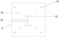
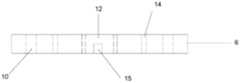
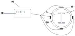
附图标记:1—型钢,11-安装通孔,2-内连杆,201—螺杆,3—螺母;4—上端板,5—约束混凝土;6—支撑板,7—球铰,8—恒载千斤顶,9—承台,91-内框架,92-外框架,93-约束应力测试装置,94-试件,10—螺纹孔,11—安装通孔,12—工字形通槽,13—位移计,131-位移采集仪,14—连接螺栓,15—预留槽,16—钢管,17—外连杆,18—荷载传感器,19—应变计,20—应变采集仪,21—反力板,22—加载千斤顶。Reference numerals: 1—section steel, 11—installation through hole, 2—inner connecting rod, 201—screw, 3—nut; 4—upper end plate, 5—confining concrete; 6—supporting plate, 7—ball hinge, 8— Dead load jack, 9-cap, 91-inner frame, 92-outer frame, 93-restrained stress testing device, 94-specimen, 10-threaded hole, 11-installation through hole, 12-I-shaped through-slot, 13 —Displacement meter, 131—Displacement acquisition instrument, 14—Connecting bolt, 15—Reserved slot, 16—Steel pipe, 17—Outer connecting rod, 18—Load sensor, 19—Strain gauge, 20—Strain acquisition instrument, 21—Reverse Force Plate, 22 - Loading Jack.
具体实施方式Detailed ways
为使本发明的上述目的、特征和优点能够更加明显易懂,下面结合附图对本发明的具体实施方式做详细的说明。In order to make the above objects, features and advantages of the present invention more clearly understood, the specific embodiments of the present invention will be described in detail below with reference to the accompanying drawings.
如图1所示,一种型钢与约束混凝土粘结性能滑移推出试验装置,包括:内框架91、外框架92、承台9、球铰7、恒载千斤顶8、加载千斤顶22、荷载传感器18、约束应力测试装置93和试件94。所述内连杆2垂直固定于承台9之上,并依次穿过支撑板6和上端板4,上端板4固定在内连杆2上,支撑板6可上下移动;外连杆17穿过反力板21垂直固定于承台9上;球铰7固定于支撑板6下部;试件94包括约束混凝土5和型钢1,约束混凝土5放置于上端板4和支撑板6之间,型钢上端穿过上端板4。As shown in Figure 1, a sliding push-out test device for the bonding performance between profiled steel and restrained concrete includes: an
如图6所示,所述约束应力测试装置93包括应变计19和应变采集仪20,应变计19安装于试件94外部,并与应变采集仪20连接;恒载千斤顶8安装于球铰7和承台9之间,其垂直向上施加荷载并保持恒定;加载千斤顶22固定于反力板21下,其竖直向下施加荷载,通过荷载传感器18将力传递到型钢1上,将型钢1推出。As shown in FIG. 6 , the restraint
上述的内连杆2包括四根螺杆201;所述四根螺杆201的下端垂直焊接于所述承台9上,其上端由下至上依次穿过所述支撑板6和上端板4,所述螺杆201通过螺母3和垫片与所述上端板4固定;所述上端板4可根据试件94的实际需要通过螺母3调节与支撑板6之间的距离,以扩大装置的适用范围。The above-mentioned inner connecting rod 2 includes four
如图2、图3所示,上述的上端板4与支撑板6开设有同轴的安装通孔11,其中,所述上端板4的安装通孔为矩形方孔,型钢1上端由此穿出;所述支撑板6中的安装通孔11为工字形通槽12,以方便型钢1的推出;所述位移计13通过螺丝固定于通孔内,用以测量型钢1下端的滑移量。As shown in FIGS. 2 and 3 , the above-mentioned
如图4、图5所示,所述支撑板6一侧开设有预留槽15,预留槽15与支撑板6中的安装通孔11相连通,以方便位移计信号传输线的布置。As shown in FIGS. 4 and 5 , a
上述的恒载千斤顶8放置在承台9上,其竖直向上施加荷载;所述球铰7放置在所述恒载千斤顶8与支撑板6之间,支撑板6上设置有螺纹孔14,所述球铰7由螺栓穿过螺纹孔14将其固定于支撑板6的下部;所述球铰7可实现试件94与恒载千斤顶8的自动对中,释放由于意外偏心产生的弯矩,能够有效地提高加载的精准性。The above-mentioned dead load jack 8 is placed on the
上述的外连杆17包括四根螺杆202所述螺杆202的下端焊接于承台9之上,其上端穿过所述反力板21,并通过螺母3与垫片和反力板21固定。所述反力板21下焊接有加载千斤顶22,加载千斤顶22竖直向下施加荷载,将型钢1推出。所述荷载传感器18布置在加载千斤顶22下,用以测量推出荷载。The above-mentioned outer connecting
如图7所示,上述的试件94包括约束混凝土5与型钢1,约束混凝土5由钢管/FRP管16和混凝土组成;在前述恒载千斤顶8的竖向荷载下,混凝土受到轴压力而产生横向膨胀,在钢管/FRP管16的横向约束下,约束混凝土5处于三轴受压状态;将型钢1沿构件轴力方向居中埋入混凝土中,其上端伸出混凝土上表面,下端与混凝土下表面平齐。As shown in FIG. 7 , the above-mentioned
上述的试件94外表面,即在钢管/FRP管16的中部表面对称设置四个应变计19,应变计19与应变采集仪20相连接,用以测量钢管/FRP管16的横向应变,通过钢管/FRP管16的应力-应变关系进而获得约束应力。The outer surface of the above-mentioned
在试验过程中按照如下步骤进行测试:During the test, follow the steps below:
步骤一:试件制作,在钢管或FRP管16中浇筑混凝土,将型钢1埋入混凝土中心,型钢1的一端伸出混凝土,另一端与混凝土表面平齐。Step 1: Make the test piece, pour concrete in the steel pipe or
步骤二:将待加载试件94放置于上端板4和支撑板6之间。型钢1上端穿过上端板4的安装通孔,下端对中于支撑板6的工字形通槽12;安装荷载传感器18,沿对角两两均匀拧紧外连杆17螺帽。Step 2: Place the
步骤三:在支撑板6的工字形通槽12下端安装位移计13,信号线通过预留槽15与位移采集仪131连接,用以测量型钢下端滑移量。Step 3: Install the
步骤四:在与竖向荷载垂直的方向上,即钢管或FRP管16中段表面布置四个应变计19,应变计19与应变采集仪20相连接,以获取试件94的约束应变值;四个应变计19环向对称布置。Step 4: In the direction perpendicular to the vertical load, that is, four
步骤五:启动恒载千斤顶8,匀速加载,同时读取约束应变值,通过钢管或FRP管16的应力-应变关系获得相应的约束应力,当约束应力达到预设值时,令恒载千斤顶8的荷载值保持恒定。Step 5: Start the dead load jack 8, load at a constant speed, and read the restraint strain value at the same time, obtain the corresponding restraint stress through the stress-strain relationship of the steel pipe or
步骤六:启动加载千斤顶22,采用荷载控制方式匀速加载,观测荷载传感器18数值与应变采集仪20的数值,当外荷载下降到较为平滑段或者滑移量达到预设值时结束加载。Step 6: Start the
步骤七:通过荷载传感器18获取的推出荷载值,位移计13获取自由端滑移量,分析出型钢1与约束混凝土5界面粘结性能。Step 7: Using the push-out load value obtained by the
采用上述技术方案,能使混凝土处于约束下的三轴受压状态下进行混凝土粘结滑移推出试验,通过约束应力测试装置、位移计可准确获取相关参数,进而分析出型钢与约束混凝土间的粘结性能,该装置结构简单,使用方便。By adopting the above technical scheme, the concrete bond-slip push-out test can be carried out under the constrained triaxial compression state, and the relevant parameters can be accurately obtained through the constrained stress test device and displacement meter, and then the relationship between the profile steel and the constrained concrete can be analyzed. Adhesive performance, the device has a simple structure and is easy to use.
以上所述仅为本发明的较佳实施例而已,并不用以限制本发明,凡在本发明的精神和原则之内所作的任何修改、等同替换和改进等,均应包含在本发明的保护范围之内。The above descriptions are only preferred embodiments of the present invention and are not intended to limit the present invention. Any modifications, equivalent replacements and improvements made within the spirit and principles of the present invention shall be included in the protection of the present invention. within the range.
Claims (7)
Priority Applications (1)
| Application Number | Priority Date | Filing Date | Title |
|---|---|---|---|
| CN202010743783.8ACN111751275A (en) | 2020-07-29 | 2020-07-29 | A sliding push-out test device and method for the bond performance between section steel and restrained concrete |
Applications Claiming Priority (1)
| Application Number | Priority Date | Filing Date | Title |
|---|---|---|---|
| CN202010743783.8ACN111751275A (en) | 2020-07-29 | 2020-07-29 | A sliding push-out test device and method for the bond performance between section steel and restrained concrete |
Publications (1)
| Publication Number | Publication Date |
|---|---|
| CN111751275Atrue CN111751275A (en) | 2020-10-09 |
Family
ID=72712316
Family Applications (1)
| Application Number | Title | Priority Date | Filing Date |
|---|---|---|---|
| CN202010743783.8APendingCN111751275A (en) | 2020-07-29 | 2020-07-29 | A sliding push-out test device and method for the bond performance between section steel and restrained concrete |
Country Status (1)
| Country | Link |
|---|---|
| CN (1) | CN111751275A (en) |
Cited By (4)
| Publication number | Priority date | Publication date | Assignee | Title |
|---|---|---|---|---|
| CN113639007A (en)* | 2021-10-12 | 2021-11-12 | 南通盛邦制辊有限公司 | Test is adjusted pipe laying ship pipe-supporting rack bearing roller load equipment |
| CN114705836A (en)* | 2022-04-15 | 2022-07-05 | 南京交通职业技术学院 | Expansive soil no-load expansion rate tester and testing method |
| CN119104489A (en)* | 2024-10-22 | 2024-12-10 | 福州大学 | A device and method for testing the bond slip between corroded steel and concrete |
| CN119223757A (en)* | 2024-12-02 | 2024-12-31 | 华侨大学 | A stress-strain constitutive test structure |
Citations (7)
| Publication number | Priority date | Publication date | Assignee | Title |
|---|---|---|---|---|
| CN203191293U (en)* | 2013-04-23 | 2013-09-11 | 金陵科技学院 | Bonding performance test device for FRP (Fiber Reinforced Plastic) rib and concrete under complex stress state |
| CN204422395U (en)* | 2015-03-17 | 2015-06-24 | 三峡大学 | Bi-directional compression steel bar concrete pulling pulling device |
| CN104833631A (en)* | 2015-02-04 | 2015-08-12 | 三峡大学 | Self-balancing reinforced concrete bonding and anchoring performance test instrument |
| CN108801906A (en)* | 2018-06-05 | 2018-11-13 | 西安建筑科技大学 | A kind of loading device and method for bond-slip properties experiment |
| KR101983628B1 (en)* | 2018-06-22 | 2019-07-22 | 비티이엔씨 주식회사 | Pile assembly and construction method of bi-directional pile load test using the same |
| CN110426344A (en)* | 2019-08-26 | 2019-11-08 | 河海大学 | A kind of self-balancing type reinforcing bar and concrete binding sliding test device and test method |
| CN110514523A (en)* | 2019-08-29 | 2019-11-29 | 广东工业大学 | A stress loading combination device |
- 2020
- 2020-07-29CNCN202010743783.8Apatent/CN111751275A/enactivePending
Patent Citations (7)
| Publication number | Priority date | Publication date | Assignee | Title |
|---|---|---|---|---|
| CN203191293U (en)* | 2013-04-23 | 2013-09-11 | 金陵科技学院 | Bonding performance test device for FRP (Fiber Reinforced Plastic) rib and concrete under complex stress state |
| CN104833631A (en)* | 2015-02-04 | 2015-08-12 | 三峡大学 | Self-balancing reinforced concrete bonding and anchoring performance test instrument |
| CN204422395U (en)* | 2015-03-17 | 2015-06-24 | 三峡大学 | Bi-directional compression steel bar concrete pulling pulling device |
| CN108801906A (en)* | 2018-06-05 | 2018-11-13 | 西安建筑科技大学 | A kind of loading device and method for bond-slip properties experiment |
| KR101983628B1 (en)* | 2018-06-22 | 2019-07-22 | 비티이엔씨 주식회사 | Pile assembly and construction method of bi-directional pile load test using the same |
| CN110426344A (en)* | 2019-08-26 | 2019-11-08 | 河海大学 | A kind of self-balancing type reinforcing bar and concrete binding sliding test device and test method |
| CN110514523A (en)* | 2019-08-29 | 2019-11-29 | 广东工业大学 | A stress loading combination device |
Cited By (5)
| Publication number | Priority date | Publication date | Assignee | Title |
|---|---|---|---|---|
| CN113639007A (en)* | 2021-10-12 | 2021-11-12 | 南通盛邦制辊有限公司 | Test is adjusted pipe laying ship pipe-supporting rack bearing roller load equipment |
| CN113639007B (en)* | 2021-10-12 | 2021-12-17 | 南通盛邦制辊有限公司 | Test is adjusted pipe laying ship pipe-supporting rack bearing roller load equipment |
| CN114705836A (en)* | 2022-04-15 | 2022-07-05 | 南京交通职业技术学院 | Expansive soil no-load expansion rate tester and testing method |
| CN119104489A (en)* | 2024-10-22 | 2024-12-10 | 福州大学 | A device and method for testing the bond slip between corroded steel and concrete |
| CN119223757A (en)* | 2024-12-02 | 2024-12-31 | 华侨大学 | A stress-strain constitutive test structure |
Similar Documents
| Publication | Publication Date | Title |
|---|---|---|
| CN111751275A (en) | A sliding push-out test device and method for the bond performance between section steel and restrained concrete | |
| CN103076192B (en) | Portable performance test device for automatic control of combined action of bidirectional load of beam-column joint and determination method | |
| CN108287103B (en) | Device and method for testing tension, strain and deflection of general planar material | |
| CN103913380B (en) | All-in-one machine for testing soil engineering tension-compression strength | |
| CN207300737U (en) | The strain full curve measuring device of concrete in uniaxial compression chord | |
| CN101446545B (en) | Anchor body rheological drawing device and test method | |
| CN101498625A (en) | Component pressing and twisting experimental device and method thereof | |
| CN105910908A (en) | Device and measuring method for measuring direct stretching mechanical parameter of rock | |
| CN103149100A (en) | Concrete axis stretching creep tester and test method thereof | |
| CN106546492B (en) | A kind of Rock And Soil large scale original position triaxial creep test system | |
| CN111751276A (en) | A loading device and method for bonding performance test of reinforcing bar and restrained concrete | |
| CN107503386A (en) | Anchor rod body holds the detection means and detection method of load | |
| CN213209873U (en) | A loading device for bonding performance test of reinforcement and restrained concrete | |
| CN106124313A (en) | Concrete and similar material are by the test device and method depressing comprehensive deformation performance | |
| CN106836315A (en) | A kind of vertical displacement detection means | |
| CN114112639B (en) | Tension-compression dual-function concrete creep test device and test method thereof | |
| CN102628774A (en) | Tension stress loading and deformation measuring device and method for measuring deformation amount of concrete test piece under tension stress | |
| CN102720220B (en) | Device and method for measuring counterforce of pile end of concrete pipe pile | |
| CN103163016A (en) | Auxiliary device for carrying out axial tension test on quasi brittle materials | |
| CN202372410U (en) | Anchor rod performance test device | |
| CN108627400A (en) | A kind of angle steel X-braced panels stability bearing capacity experimental rig and method | |
| CN207019989U (en) | A kind of general planar material tension, strain and deflection test device | |
| CN104344997B (en) | Passive type restraint loading device for triaxial test | |
| CN203881614U (en) | All-in-one machine for geo-technical tension-compression strength test | |
| CN108776066B (en) | Anchor head tension test device and anchor head tension test method |
Legal Events
| Date | Code | Title | Description |
|---|---|---|---|
| PB01 | Publication | ||
| PB01 | Publication | ||
| SE01 | Entry into force of request for substantive examination | ||
| SE01 | Entry into force of request for substantive examination | ||
| CB03 | Change of inventor or designer information | Inventor after:Zhou Chunheng Inventor after:Lin Jingyu Inventor after:Wang Junyi Inventor after:Lang Yicheng Inventor after:Ran Yaqin Inventor before:Zhou Chunheng Inventor before:Pan Jinjing Inventor before:Wang Bing Inventor before:Lin Fanxuan | |
| CB03 | Change of inventor or designer information | ||
| RJ01 | Rejection of invention patent application after publication | Application publication date:20201009 | |
| RJ01 | Rejection of invention patent application after publication |